1
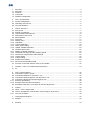
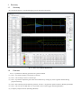
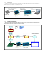
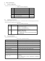
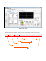
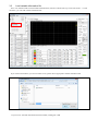
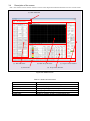
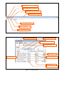
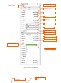
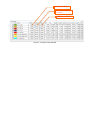
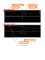
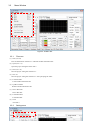
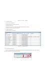
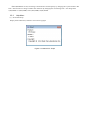
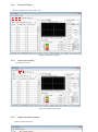
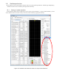
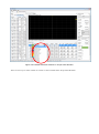
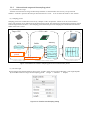
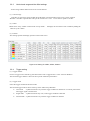
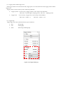
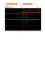
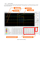
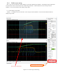
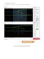
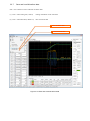
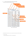
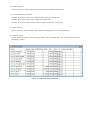
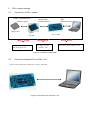
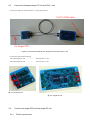
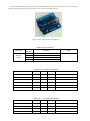
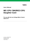
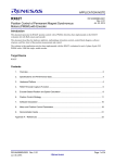
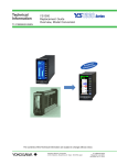
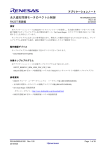
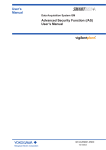
In Circuit Scope Plus (ICS++ W1004) User’s manual Real time variable waveform viewer In Circuit Scope Plus is the tool which shows the waveform of the global variables running on the target CPU. This manual shows how to use “In Circuit Scope plus” ※Caution November 1, 2014 now, conventional ICS board is not able to drive by the new ICS++ PC software. However, target side conventional library can be use in the new ICS++ system. Target CPU devices ICS system is working on following devices. 〇16bit devices: RL78/G1F, RL78/G14, RL78/F14, RL78/F13, RL78/G12, RL78/G13, 78K0RIC3, 78K0R/ID3, 78K0R/IE3 〇32bit interger type devices: RX111, RX210, RX220, V850/IA3, V850/IA4, V850E2/IG3, V850E/FJ3, SH7047, SH7146, SH7149, SH7237, 〇32bit floating point support type devices: RX23T, RX62T, RX63T, RX631, RX64M, RX71M, V850E2M/FJ4, V850E2/ML4, SH7216, SH7239, For more information about support for other devices, please contact DESK TOP LABORATORIES INC. http://desktoplab.co.jp With the development of target-side library, ICS system can work on more than 16bit of RENESAS Electronics devices. AboutlICS/ICS++ ICS is the product of the Renesas Electronics Corporation. Desk Top Laboratories Inc supports how to use ICS system and the development of the ICS target libraries. ICS++ is the product of the Desk Top Laboratories Inc. 目次 1. 1.1 1.2 1.3 1.4 Summary ........................................................................................................................................... 3 Summary ........................................................................................................................................... 3 Features ............................................................................................................................................ 3 Connection ........................................................................................................................................ 4 Software configuration....................................................................................................................... 4 2. 2.1 2.2 2.3 ICS++ specifications.......................................................................................................................... 5 Product configuration ........................................................................................................................ 5 Operating environment ...................................................................................................................... 5 Tool specifications ............................................................................................................................. 5 3. 3.1 3.2 3.3 3.4 3.5 3.5.1 3.5.2 3.5.3 3.5.4 3.5.5 3.5.6 3.6 3.6.1 3.6.2 3.6.3 3.6.4 3.6.5 3.6.6 3.6.7 3.7 How to use ICS++ ............................................................................................................................. 7 Flow of use ........................................................................................................................................ 7 Startup PC software .......................................................................................................................... 8 Load variable information file .......................................................................................................... 10 Description of the screen ................................................................................................................ 12 Menu Window.................................................................................................................................. 17 File menu ......................................................................................................................................... 17 Setting menu ................................................................................................................................... 17 Help Menu ....................................................................................................................................... 19 Choose COM port ........................................................................................................................... 20 Open project setting ........................................................................................................................ 20 Update variable information ............................................................................................................ 20 Oscilloscope function ...................................................................................................................... 22 Setting of variable waveform ........................................................................................................... 22 Horizontal axis range and the sampling period ............................................................................... 24 Vertical axis range and the offset settings ...................................................................................... 25 Trigger setting ................................................................................................................................. 25 Cursor setting .................................................................................................................................. 28 ZOOM screen setting ...................................................................................................................... 29 Save and Load Waveform data ....................................................................................................... 31 Function of read and write the value of the variable ....................................................................... 32 4. Installing 4.1 34 ICS++ PC software (DTLScope.exe) ............................................................................ 34 5. 5.1 5.2 5.3 5.4 5.4.1 5.4.2 5.5 ICS++ system settings .................................................................................................................... 35 Connection of ICS++ system .......................................................................................................... 35 Connection between PC and ICS++ unit ........................................................................................ 35 Connection between target I/F unit and ICS++ unit ........................................................................ 36 Connect the target CPU and the target I/F unit ............................................................................... 36 Electrics specification ...................................................................................................................... 36 Example of the terminal connections .............................................................................................. 38 Examples of the ICS++ unit, target I/F unit and target CPU ........................................................... 38 6. 6.1 6.2 6.2.1 Caution ............................................................................................................................................ 39 About ICS++ support CPU ........................................................................................................... 39 How to calculate the communication clock frequency of the ICS++ ............................................... 39 The case of RX62T ......................................................................................................................... 39 7. Homepage and Support .................................................................................................................. 39 7.1 Support ............................................................................................................................................ 39 8. Revision ........................................................................................................................................... 40 1. 1.1 Summary Summary In Circuit Scope Plus is a real time debugging tool for the Power Electronics. 図 1-1 ICS++ PC software appearance 1.2 Features ICS++ is possible for following operations on a global variables. (1) ICS++ is possible to display a waveform in real time. (2) ICS++ can be used just same as oscilloscope. (3) ICS++ is possible to adjust the gain of the control software by writing any value to global variables during program executing. (4) ICS++ has a function just like function generator. So ICS++ can generate operation pattern. (Planning OPTION) (5) ICS++ can save the recorded data. So it is possible to use as a data logger. (Planning OPTION) (6) Frequency analysis function (Planning OPTION) 1.3 Connection Connect to a PC from the target processor via the ICS++ unit. Please refer to the Section 3.1 “flow of the use”. In addition, please refer to Chapter 4 regarding ICS++ unit. Optical fiber communication UART communication Electric signal Target CPU USB communication PC Target I/F unit ICS++ unit 図 1-2 Hardware configuration 1.4 Software configuration Based on the variable names and memory address information, ICS++ processes the data to be transmitted via the ICS unit from the target CPU, to display the waveform on the PC. ICS Libraries Source file Compiler Object file Variable information Variable information file generator Linker Map file Binary file ICS++ Target board Target I/F unit ICS++ unit 図 1-3 Software configuration 2. ICS++ specifications 2.1 Product configuration This product contains the following parts and units. Table 2-1 Product configuration No. 1 2 3 4 5 6 Item In Circuit Scope Plus unit Target I/F unit (for 5V CPU) Target I/F unit (for 3.3V CPU) Optical fiber 2m USB cable Target I/F cable 1 single side XHP-4 Target I/F cable 2 both side XHP-4 (From 2014/12/19) USB memory 7 (8) 2.2 1 1 1 2 1 1 1 1 Operating environment Specifications required in order to install the ICS++ is shown below. But we recommend high specification PC. Waveform refresh rate depends on PC specifications. Table 2-2 Operating environment No. 2.3 Item 1 PC 2 OS Specifications Free disk space: more than 100MByte RAM: more than 1GByte USB port : 1 [channel](USB2.0) .Net framework client 4.5 installed Windows Vista 32bit, Windows 7 32bit / 64bit *Windows 8 32bit / 64bit Windows 8/8.1 requires a special install procedure to install software. Tool specifications The specifications summary list of ICS++ Table 2-3 ICS++ specification summary Item Measurement period Specifications It depends on the library installed in the target CPU. Waveform measurement channel Max 8 channel Measurement variable type It depends on the library installed in the target CPU. Trigger mode Single / Auto / Normal Trigger source Input channel Numeric display channel number Max 48 variables Data management Save and Load function of the waveform data Waveform display screen Main screen + Zoom screen Occupied UART port TXD, RXD Occupied peripheral function UART 1 channel, DMA or DTC, (FIFO) Support CPU It depends on the ICS unit model. ( 8 channel ) 16bit RL78G14, RL78F14, RL78G1F, RL78G12, RL78G13, 78K0R/Ix3 32bit RX62T, RX63T, RX64M, V850E2M/FJ4, V850E2/ML4, SH7216, SH7239 32bit RX111, RX210, RX220, V850E2/IG3, SH7047, SH7146, SH7149, SH7237 Most of the 16/32bit Renesas CPU can use ICS function. Please contact Desk Top Laboratories Inc for specific CPU support. December 1, 2014, RL78G1G can not be use and has been confirmed. 3. How to use ICS++ 3.1 Flow of use When using ICS++, please prepare the order of (1) to (9). (1) Connect ICS++ unit and the target CPU board (Please refer Chapter 4) (2) Connect ICS++ unit and the PC via USB cable. (3) Supply power to the target board. (4) Download the user program to the target CPU board. (5) Execute program (6) Start ICS++ software on PC(Section 3.2) (7) Check the establishment of the communication(Section 3.2) (8) Load the variable information file.(Section 3.3) (9) Ready 3.2 Startup PC software Execute DTLScope.exe, then the main screen will appear. Figure 3-1 Main screen When the communication is established, communication port is selected automatically. And the communication status is displayed at the status bar. The name of ICS++ and version Target CPU library version Target CPU name and port number Connection status with target CPU Communication base clock frequency Figure 3-2 Status bar When PC cannot recognize the ICS++ unit, “Disconnected” is displayed at the status bar. When displayed this message, please refer Section 3.1. Figure 3-3 Status bar (when PC cannot recognize ICS++ unit) When PC recognize the ICS++ unit and cannot recognize the target unit, PC software displays “Disconnected, Scope: I.C.Scope++, Hardware: Model 7, Ver.1, Software Ver.1.35, Clock: 8Mhz” PC software shows only ICS++ unit name and the version, not shows CPU name and the library version. figure 3-4 Status bar (when PC recognize only ICS++ unit) when PC recognize the ICS++ unit and the target CPU, PC software displays “Connected, CPU:R5F10PMF/SCI0, Library: Ver2.0, Scope: I.C.Scope++, Hardware: Model 7, Ver.1, Software Ver.1.35, Clock: 8Mhz” PC software shows both ICS++ unit information and the target CPU information. Figure 3-5 Status bar (when PC recognize both ICS unit and the target CPU) 3.3 Load variable information file ICS++ PC software needs to load variable information file, after PC software stats up. Click “File memu” -> “Load variables”, you can load variable information file. Figure 3-6 Load Variables If you click Load variables, you can see below screen, please choose appropriate variable information file. figure 3-7 Screen of choosing variable information file If you can see ”Variable information has been loaded”, loading file is OK. Figure 3-8 Success to load variable information file 3.4 Description of the screen ICS++ PC software screen consists of the five screens. This chapter describes the functional overview in each screen. (a). Main Menu Bar (e). Watch Window (f). Status Bar (b). Main Scope Window (c). Scope Control Window (d). Scope Value Window Figure 3-9 Default screen Table 3-1 Outline of each screen Name of screen (a) Main Menu Bar (b) Main Scope Window (c) Scope Control Window (d) Scope Value Window (e) Watch Window (f) Status Bar Functional overview Data save, Data load, Screen setting Waveform display screen Setting range, trigger and so on ( For scope function ) Setting range and display the numeric data of the waveform Read and write a variable data Display a condition of ICS++ unit and target CPU File Menu Setting Menu Help Menu Menu / Tool bar Variable update button Project open button Connecting COM port Figure 3-10 Main Menu Bar Read update variable data Write variable data ダタ変数値を一度読み 込み Read variables automatically Auto Read interval Write data ダタ書き込み変 数値 Write enable check box Variable name Readout data ダタ読み込み Read enable check box 変数値 Figure 3-11 Watch window Setting Time/Div Waveform viewer start/stop button Sampling period Record data length Trigger position Trigger level Trigger source Trigger mode Trigger edge Display variable Display variable range Vertical position Variable offset Enable waveform display check box Color of the waveform Figure 3-12 Scope controls window Waveform display on/off setting Choose variable to display Display range setting Vertical position of the waveform Offset of the variable Figure 3-13 Scope Value Window Main Scope Chart information Main Scope Chart Cursor position Trigger level Zoom Scope Chart information Zoom Scope Chart Figure 3-14 Main Scope Window 3.5 Menu Window Figure 3-15 Menu bar 3.5.1 File menu (1) New (Ctrl+N) Clear all information of the ICS++ and load variable information file. (2) Open (Ctrl + O) Open the project setting file of the ICS++ (3) Save (Ctrl + S) Save the project setting file of the ICS++ (4) Save As Save the project setting file of the ICS++ with specifying file name. (5) Load Variables Load variable information file (6) Update Variables Reload variable information file (7) Save Chart Data Save Chart data (8) Load Chart Data Load Chart data (9) Close Exit ICS++ 3.5.2 Setting menu Figure 3-16 Menu ⇒ Setting (1) Variables Settings Modify variable information. Variable Settings menu has these functions A) Modify variable type B) When the variable type is integer, this function enables scaling to variable. C) Enable and disable read and write function D) Alias variable name. E) Put a comment on a variable. Figure 3-17 Variable Settings (2) Communication Settings Set a new communication rate. It can change a communication clock frequency. Please set the clock, which is specified in the function of each ICS library manual. Figure 3-18 Communication Settings ※ICS (RENESAS version) can change communication clock frequency by changing the crystal oscillator. But ICS++ has a function to change variable clock function. By changing this clock setting ICS++ can change from 5,000,000Hz to 10,000,000Hz, and 12,000,000Hz, 24,000,000Hz. 3.5.3 Help Menu (1) About DTLScope Display the Product name, Software version and Copyright Figure 3-19 About DTL Scope 3.5.4 Choose COM port Choose a COM port to connect ICS++ unit. Figure 3-20 Choose COM port 3.5.5 Open project setting Open project to be set. Figure 3-21 Open project setting 3.5.6 Update variable information Update variable information Figure 3-22 Update variable information 3.6 Oscilloscope function In this chapter we show the necessary setting in order to use the oscilloscope function. Variable type of displaying variable waveform can be variable by the target CPU ICS library. 3.6.1 Setting of variable waveform From pull down button of the variable name in the “Scope Controls Window” or “Scope Values Window, you can select variable name to be shown. And you can also set the variable by typing name directly. Figure 3-23 Variable name selection window in “Scope Control Window” Figure 3-24 Variable selection windows in “Scope Value Window” There are two ways to select variable. It is easier to select variables from “Scope Value Window” 3.6.2 Horizontal axis range and the sampling period (1) Horizontal axis range Time/Div of horizontal axis range of Main Scope Window or Zoom Window can be set by “Scope Controls Window”. Time/Div represents the time per the horizontal axis 1 scale. It can set from 100 us/Div to 262.14s/Div. (2) Sampling period Sampling period of a variable data can be set by “Sample” of the “Acquisition” column. It can be set from 20us to 10ms. This sampling rate is different from the measurement period. The measurement period means transferring period from the target CPU to the ICS++ unit. Sampling period means the period for sampling the variable data stored in the buffer of the ICS++ board. Target CPU RAM Variable Data A PC ICS++unit Memory Buffer Variable Data A Variable data An n ・ ・ Measurement period Display data Variable data A2 Sampling period Variable data A1 Figure 3-25 Difference between sampling period and measurement period (3) Record length Record length of the measured data is shown in the “Length” of the “Scope Controls Window”. This length depends 横 on the Horizontal axis range and the sampling period. (Length = Time/Div ÷ Sample) Figure 3-26 Time/Div and Sampling setting 3.6.3 Vertical axis range and the offset settings Vertical range and the offset need to be set in each channel. (1) Vertical range Time/Div of vertical axis range of Main Scope Window or Zoom Window can be set by “Scope Controls Window”. Time/Div represents the value per the vertical axis 1 scale. It can set from 1p/Div to 1T/Div. (2) Offset Offset can be set by “Offset” column of the “Scope Value”. value set by the “offset”. It displays the waveform to each variable by adding the (3) Position This setting specifies the display position on the whole screen. Figure 3-27 Setting of Val/Div, Offset, Position 3.6.4 Trigger setting (1) Trigger channel Choose a trigger source channel by pull-down menu of the “Trigger Source” in the “Controls Window”. The selected trigger channel is shown at the top of the “Main Scope Window”. (2) Trigger mode Select the trigger mode from the three mode. The selected trigger mode is shown at the top of the “Main Scope Window”. Auto mode :Update waveform every time the trigger condition is detected or if a certain period of the time trigger signal is not detected. Single mode :Update waveform only once, if the trigger condition is detected. Normal mode :Update waveform every time the trigger condition is detected. (3) Trigger position and the trigger level If the trigger channel is set from CH1 to CH8, Trigger point is set to the intersection of the trigger position and the trigger level. Trigger position is shown at the top of the “Main Scope Window”. Trigger position:It can be set by “Trigger position” in the ”Scope control Window”. (Max value:Record length * sampling period、Min value:sampling period) Trigger level :It can be set by “Trigger level” in the ”Scope control Window”. (Max value:Val/Div * 5、 Min value:Val/Div * (-5)) (4) Trigger edge Trigger edge can be choose from below three type of conditions. Rise :Rising edge Fall :Falling edge Both :Both rising and falling edge Figure 3-28 Trigger setting (1) Trigger position cursor Trigger level cursor Figure 3-29 Trigger setting (2) 3.6.5 Cursor setting The value of the intersection of the waveform and the four cursors “Cursor X1”, “Cursor X2”, Cursor Y1”, “Cursor Y2” are shown at the bottom of the “Scope Value Window”. ON and OFF of the cursor is set by the check box in the “Scope Controls Window”. Cursor Y2 Cursor X1 Cursor X2 Cursor Y1 Cursor measurement value Cursor ON/OFF setting Figure 3-30 Cursor setting 3.6.6 ZOOM screen setting ICS++ has one zoom function which enhances a part of the “Main Scope Window”. The display range of the Zoom screen has been shown in the frame on the “Main Scope Window”. And the check box in the “Scope Controls Window” can set ON and OFF of the display range frame. (1) Zoom display range width “Zoom” ⇒ the Spin control of “Sec/Div” in the “Scope Controls Window” can be set the width of the Zoom display range width. Zoom range width setting Zoom range width frame Figure 3-31 Zoom range width setting (2) Zoomed display start position This value can be set in the “Zoom” ⇒ “Position” in the “Scope Controls Window” Zoomed display start position Figure 3-32 Zoomed display start position setting 3.6.7 Save and Load Waveform data ICS++ has a function of save and load waveform data. (1) ICS++ Chart setting file (*.dtlcd) : Setting information of the waveform (2) ICS++ Chart Data File(*.dtlcd.csv) :Raw waveform data Save waveform data Load waveform data Figure 3-33 Save and Load waveform data 3.7 Function of read and write the value of the variable This chapter shows the function of read and write variable. Read variable once Write variable once Read variable at a certain interval Set read interval Choose variable Write value Write enable check box Read value Read enable check box Figure 3-34 Watch Window By manipulating the order from (1) to (5), it is possible to use the function of read/write variables. (1) Choose variable Choose variable name from the “Name” in the “Watch Window”. (2) Enable read/write Check the check box of the R and W raw, then it enables the read and write functions. (3) Execute Read/Write/Auto Read Click the “Read button”, then read a variable from the target CPU and display it. Click the “Write button”, then write a variable to the target CPU. Click the “Auto Read” button, then PC software read the variables at a certain period. (4) Choose data type You can modify the default variable type by changing “Modified type” in the “Variable Setting”. (5) Scale rate setting You can modify the scaling value by changing “Scale” in the “Variable Setting”. This setting is also active to the chart display window. Figure 3-35 Variables Settings Window 4. 4.1 Installing ICS++ PC software (DTLScope.exe) 5. ICS++ system settings 5.1 Connection of ICS++ system UART communication Electric signal Target CPU Optical fiber communication PC Target I/F unit 4.4 Connection target CPU and the target I/F unit USB communication ICS++ unit 4.3 Target I/F unit and ICS++ unit Figure 5-1 Hardware configuration 5.2 Connection between PC and ICS++ unit Please connect between PC and the ICS++ unit by USB cable. Figure 5-2 Connection PC and ICS++ unit 4.2 Connection PC and ICS++ unit 5.3 Connection between target I/F unit and ICS++ unit Connect the target I/F unit and the ICS++ unit by optical fiber. To PC (USB cable) To Target CPU Figure 5-3 Connection between the target I/F unit and the ICS++ unit Connect the optical fiber following TX of the Target I/F unit <-> RX of the ICS++ unit RX of the Target I/F unit <-> TX of the ICS++ unit 図 5-4 Target I/F unit 図 5-5 Target I/F unit 5.4 5.4.1 Connect the target CPU and the target I/F unit Electrics specification Connect 4pin connector of the target I/F unit to the target CPU. If the 5V I/O CPU, please use 5V version of the target I/F unit. If the 3.3V I/O CPU, please use 3.3V version of the target I/F unit. Figure 5-6 5V version of the target I/F unit Table 5-1 4pin connector Connector XH 4pin (JAE) Pin number 1 2 3 4 function Vcc To CPU の TXD port To CPU の RXD port GND Table 5-2 Item Vcc voltage Note 5V version specification MIN Typ MAX 4.75V 5.00V 5.50V 17mA 40mA Icc High level input voltage 2.0V Vcc Low level input voltage 0V 0.8V Note High level output voltage 3.5V - - Vcc=4.75V, Ioh=-150uA Low level output voltage - - 0.4V Vcc=4.75V IoL=2.0mA Table 5-3 Item Vcc voltage 3.3V version specification MIN Typ MAX 3.0V 3.3V 3.6V 17mA 40mA Icc High level input voltage 2.0V Vcc Low level input voltage 0V 0.8V Note High level output voltage 2.4V Low level output voltage - 5.4.2 - - Vcc=3.0V, Ioh=-24mA 0.55V Vcc=3.0V IoL=24mA Example of the terminal connections TXD / RXD pin of the target CPU need to connect approximately 10kΩ〜47kΩ pull up resister to the same voltage as the I/O pins. 5.5 Examples of the ICS++ unit, target I/F unit and target CPU ※1: TXD and RXD pin need to pull up by around 10kΩ to 47kΩ resister. ※2: When you use 3.3V I/O CPU, please choose 3.3V target I/F unit. When you use 5V I/O CPU, please choose 5V target I/F unit. 6. Caution 6.1 About ICS++ support CPU Note on the use of ICS++ is shown below. ICS++ can be used in the most of 16bit/32bit RENESAS CPU. At December 18, 2014. The only RL78G1G cannot use ICS. Please ask Desk Top Laboratories, if you want use dedicated CPU. 6.2 How to calculate the communication clock frequency of the ICS++ 6.2.1 The case of RX62T As a library that supports the ICS++ function in RX62T, there are the ICS library and ICS++ library. A) The case of ICS library When modifying the CPU clock, you need to set clock frequency in the ICS++ PC software. Setting ⇒ Communication Settings This clock frequency need to calculate following equation, Clock _ frequency PCLK / 6 B) ICLK PCLK Clock 80MHz 40MHz 6.667MHz 96MHz 48MHz 8MHz (Default) 100MHz 50MHz 8.333MHz The case of ICS++ library How to calculate the clock frequency is the same as the ICS libray. 7. 7.1 Homepage and Support Support Desk Top Laboratories Inc Homepage http://desktoplab.co.jp/ frequency Contact [email protected] 8. Revision Rev. 1.03EN 1.05EN Date 2014.12.29 2015.11.10 ICS++ PC software Version Ver.1.00.00 Ver.1.00.00 Page First release Add CPU list that works on ICS system All trademarks and registered trademarks are the property of their respective owners