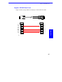
1
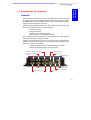
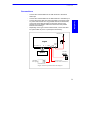
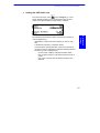
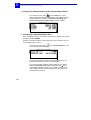
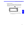
NOTICE: This manual contains the essential information needed to set up and operate your Sagitta when associated with a vibrator system. This manual sometimes refers to the Sagitta Series User Manual provided as standard with the presently discussed Sagitta. If you need more information about any particular subject regarding the Sagitta receiver, please also refer to the aforementioned manual. Copyright Notice Copyright Ó 2002 Thales Navigation. All rights reserved. No part of this publication or the computer programs described in it may be reproduced, translated, stored in a retrieval system, or transmitted in any form or by any means, electronic, mechanical photocopying, recording, or otherwise, without prior written permission of Thales Navigation. Your rights with regard to this publication and the computer programs are subject to the restrictions and limitations imposed by the copyright laws and/or the jurisdiction in which you are located. Printed in France. Part No. P0101539, Revision A September 2002 Trademarks All products and brand names mentioned in this publication are trademarks or registered trademarks of their respective holders. Thales Navigation Corporate Headquarters, Santa Clara, CA, USA +1 408 615 5100 · Fax +1 408 615 5200 Toll Free (Sales in USA/Canada) 1 800 922 2401 Email [email protected] In Washington, D.C. +1 703 476 2212 · Fax +1 703 476 2214 In South America +56 2 234 56 43 · Fax +56 2 234 56 47 In China +86 10 6566 9566 · Fax +86 10 6566 0246 European Headquarters, Carquefou, France +33 2 28 09 38 00 · Fax +33 2 28 09 39 39 Email professional [email protected] In Germany +49 81 6564 7930 · Fax +49 81 6564 7950 In Russia +7 095 956 5400 · Fax +7 095 956 5360 In the U.K. +44 1993 8867 66 · Fax +44 1993 8867 67 In The Netherlands +31 78 61 57 988 · Fax +31 78 61 52 027 Web site www.thalesnavigation.com Conventions used: § symbol indicates end of section. THALES NAVIGATION PRODUCTS LIMITED WARRANTY All Thales Navigation global positioning system (GPS) receivers are navigation aids, and are not intended to replace other methods of navigation. Purchaser is advised to perform careful position charting and use good judgment. READ THE USER GUIDE CAREFULLY BEFORE USING THE PRODUCT. 1. THALES NAVIGATION WARRANTY Thales Navigation warrants their GPS receivers and hardware accessories to be free of defects in material and workmanship and will conform to our published specifications for the product for a period of two years from the date of original purchase or such longer period as required by law. THIS WARRANTY APPLIES ONLY TO THE ORIGINAL PURCHASER OF THIS PRODUCT. In the event of a defect, Thales Navigation will, at its option, repair or replace the hardware product with no charge to the purchaser for parts or labor. The repaired or replaced product will be warranted for 90 days from the date of return shipment, or for the balance of the original warranty, whichever is longer. Thales Navigation warrants that software products or software included in hardware products will be free from defects in the media for a period of 30 days from the date of shipment and will substantially conform to the then-current user documentation provided with the software (including updates thereto). Thales Navigation's sole obligation shall be the correction or replacement of the media or the software so that it will substantially conform to the then- current user documentation. Thales Navigation does not warrant the software will meet purchaser’s requirements or that its operation will be uninterrupted, error-free or virusfree. Purchaser assumes the entire risk of using the software. 2. PURCHASER’S REMEDY PURCHASER’S EXCLUSIVE REMEDY UNDER THIS WRITTEN WARRANTY OR ANY IMPLIED WARRANTY SHALL BE LIMITED TO THE REPAIR OR REPLACEMENT, AT THALES NAVIGATION’S OPTION, OF ANY DEFECTIVE PART OF THE RECEIVER OR ACCESSORIES WHICH ARE COVERED BY THIS WARRANTY. REPAIRS UNDER THIS WARRANTY SHALL ONLY BE MADE AT AN AUTHORIZED THALES NAVIGATION SERVICE CENTER. ANY REPAIRS BY A SERVICE CENTER NOT AUTHORIZED BY THALES NAVIGATION WILL VOID THIS WARRANTY. 3. PURCHASER’S DUTIES To obtain service, contact and return the product with a copy of the original sales receipt to the dealer from whom you purchased the product. Thales Navigation reserves the right to refuse to provide service free-of-charge if the sales receipt is not provided or if the information contained in it is incomplete or illegible or if the serial number is altered or removed. Thales Navigation will not be responsible for any losses or damage to the product incurred while the product is in transit or is being shipped for repair. Insurance is recommended. Thales Navigation suggests using a trackable shipping method such as UPS or FedEx when returning a product for service. 4. LIMITATION OF IMPLIED WARRANTIES EXCEPT AS SET FORTH IN ITEM 1 ABOVE, ALL OTHER EXPRESSED OR IMPLIED WARRANTIES, INCLUDING THOSE OF FITNESS FOR ANY PARTICULAR PURPOSE OR MERCHANTABILITY, ARE HEREBY DISCLAIMED AND IF APPLICABLE, IMPLIED WARRANTIES UNDER ARTICLE 35 OF THE UNITED NATIONS CONVENTION ON CONTRACTS FOR THE INTERNATIONAL SALE OF GOODS. Some national, state, or local laws do not allow limitations on implied warranty or how long an implied warranty lasts, so the above limitation may not apply to you. 5. EXCLUSIONS The following are excluded from the warranty coverage: (1) periodic maintenance and repair or replacement of parts due to normal wear and tear; (2) batteries; (3) finishes; (4) installations or defects resulting from installation; (5) any damage caused by (i) shipping, misuse, abuse, negligence, tampering, or improper use; (ii) disasters such as fire, flood, wind, and lightning; (iii) unauthorized attachments or modification; (6) service performed or attempted by anyone other than an authorized Thales Navigations Service Center; (7) any product, components or parts not manufactured by Thales Navigation, (8) that the receiver will be free from any claim for infringement of any patent, trademark, copyright or other proprietary right, including trade secrets (9) any damage due to accident, resulting from inaccurate satellite transmissions. Inaccurate transmissions can occur due to changes in the position, health or geometry of a satellite or modifications to the receiver that may be required due to any change in the GPS. (Note: Thales Navigation GPS receivers use GPS or GPS+GLONASS to obtain position, velocity and time information. GPS is operated by the U.S. Government and GLONASS is the Global Navigation Satellite System of the Russian Federation, which are solely responsible for the accuracy and maintenance of their systems. Certain conditions can cause inaccuracies which could require modifications to the receiver. Examples of such conditions include but are not limited to changes in the GPS or GLONASS transmission.). Opening, dismantling or repairing of this product by anyone other than an authorized Thales Navigation Service Center will void this warranty. 6. EXCLUSION OF INCIDENTAL OR CONSEQUENTIAL DAMAGES THALES NAVIGATION SHALL NOT BE LIABLE TO PURCHASER OR ANY OTHER PERSON FOR ANY INDIRECT, INCIDENTAL OR CONSEQUENTIAL DAMAGES WHATSOEVER, INCLUDING BUT NOT LIMITED TO LOST PROFITS, DAMAGES RESULTING FROM DELAY OR LOSS OF USE, LOSS OF OR DAMAGES ARISING OUT OF BREACH OF THIS WARRANTY OR ANY IMPLIED WARRANTY EVEN THOUGH CAUSED BY NEGLIGENCE OR OTHER FAULT OFTHALES NAVIGATION OR NEGLIGENT USAGE OF THE PRODUCT. IN NO EVENT WILL THALES NAVIGATION BE RESPONSIBLE FOR SUCH DAMAGES, EVEN IF THALES NAVIGATION HAS BEEN ADVISED OF THE POSSIBILITY OF SUCH DAMAGES. Some national, state, or local laws do not allow the exclusion or limitation of incidental or consequential damages, so the above limitation or exclusion may not apply to you. 7. COMPLETE AGREEMENT This written warranty is the complete, final and exclusive agreement between Thales Navigation and the purchaser with respect to the quality of performance of the goods and any and all warranties and representations. THIS WARRANTY SETS FORTH ALL OF THALES NAVIGATION’S RESPONSIBILITIES REGARDING THIS PRODUCT. THIS WARRANTY GIVES YOU SPECIFIC RIGHTS. YOU MAY HAVE OTHER RIGHTS WHICH VARY FROM LOCALITY TO LOCALITY (including Directive 1999/44/EC in the EC Member States) AND CERTAIN LIMITATIONS CONTAINED IN THIS WARRANTY MAY NOT APPLY TO YOU. 8. CHOICE OF LAW This limited warranty is governed by the laws of France, without reference to its conflict of law provisions or the U.N. Convention on Contracts for the International Sale of Goods, and shall benefit Thales Navigation, its successors and assigns. THIS WARRANTY DOES NOT AFFECT THE CONSUMER'S STATUTORY RIGHTS UNDER APPLICABLE LAWS IN FORCE IN THEIR LOCALITY, NOR THE CUSTOMER'S RIGHTS AGAINST THE DEALER ARISING FROM THEIR SALES/PURCHASE CONTRACT (such as the guarantees in France for latent defects in accordance with Article 1641 et seq of the French Civil Code). --For further information concerning this limited warranty, please call or write: Thales Navigation SA – ZAC La Fleuriaye – BP 433 – 44474 Carquefou Cedex – France. Phone: +33 (0)2 28 09 38 00, Fax: +33 (0)2 28 09 39 39 Sagitta 01 Receiver Table of Contents Table of Contents 1. Equipment Description ________________________________ 1 Preamble _________________________________________________________ Standard Supply ___________________________________________________ Optional Supply____________________________________________________ Specifications _____________________________________________________ q Basic Performance Figures ____________________________________________ q Interfacing Capability_________________________________________________ q Other Characteristics _________________________________________________ Pinout Information _________________________________________________ 2. 1 2 3 3 3 3 3 3 Installation_________________________________________ 5 Mounting Sagitta in a Vibrator Truck ___________________________________ 5 q Case Dimensions ____________________________________________________ 5 q Space Required in the Cabin ___________________________________________ 5 q Drilling Diagram _____________________________________________________ 6 Mounting the GPS antenna ___________________________________________ 7 q Antenna Mounting ___________________________________________________ 7 Mounting the UHF antenna ___________________________________________ 8 Connections ______________________________________________________ 9 TRM100 Software Installation________________________________________ 10 VIV30001 Software Installation ______________________________________ 10 q Diskette Content ___________________________________________________ 10 q Loading the Vibro Software on Husky MP 2500 ___________________________ 11 3. Preliminary Settings _________________________________ 13 Possible Setups ___________________________________________________ 13 Preliminary Settings Using Viv30001 Software ___________________________ 14 q Running the Vibro Program on Palmtop _________________________________ 15 q Setting the UHF Radio Link ___________________________________________ 17 q Viewing the Characteristics of the Selected Base Station ____________________ 18 q Checking the Operating Mode Used ____________________________________ 18 q Checking the Outputs _______________________________________________ 19 q Viewing the Generated $GPGGA Sentences ______________________________ 20 q Initializing the Position Processing & Entering the GPS Antenna Height above the Ground ___________________________________________________________ 21 q Setting the Date & time______________________________________________ 22 q Viewing the status of the GPS constellation ______________________________ 23 q Viewing your current position _________________________________________ 24 q Rejecting satellites__________________________________________________ 25 q Other Functions ____________________________________________________ 25 Preliminary Settings Using TRM100 Software ____________________________ 26 q Setting the UHF Radio Link ___________________________________________ 27 i Sagitta 01 Receiver Table of Contents q Viewing the Characteristics of the Selected Base Station ____________________ 28 q Monitoring the Base Station Received___________________________________ 29 q Setting the EDGPS Operating Mode ____________________________________ 30 q Setting the Output __________________________________________________ 31 q Initializing Position__________________________________________________ 33 q Setting the Date & Time _____________________________________________ 34 q Viewing the Generated $GPGGA Sentences ______________________________ 35 End of Preliminary Settings__________________________________________ 35 4. Appendices ________________________________________ 37 Turning On and Off Sagitta__________________________________________ 37 Introduction to the VIV30001 user interface ____________________________ 39 q Main menu screen __________________________________________________ 40 q Function menus ____________________________________________________ 40 q Help menus _______________________________________________________ 40 q Other important keys________________________________________________ 41 q Making changes to parameters ________________________________________ 42 q Messages and alarms _______________________________________________ 43 Establishing Communication with Sagitta from the TRM100 Software _________ 44 Sagitta / VE432 Data Cord __________________________________________ 45 ii Equipment Description Preamble Equipment Description 1. Equipment Description Preamble When involved in vibroseismic surveys, the Sagitta receiver is simply used as a GPS sensor used in EDGPS or KART/LRK mode. Basically, it generates NMEA0183 messages ($GPGGA) to be sent to the central acquisition system via the local vibrator control unit. Sagitta receives differential data from a base station through a UHF radio link. The base station may be one of the following: - Scorpio 6001/2 SK - Scorpio 6501/2 SK - Sagitta 01 or 02 Reference Station - New Aquarius 01 or 02 Reference Station Once Sagitta has been properly set up and installed in the cabin, getting it started is as simple as switching on a bulb. Sagitta is of the "black box" type and so, if changes have to be made to its settings, this should be done from an external unit using appropriate software. Two solutions are available: - Viv30001 Software running on MP2500 palmtop computer TRM100 PC Software running on PC computer. To TRM 100 Terminal Option, if used Output to VGA screen Control Push-Button Power LED 1 PPS Output DGPS/DGNSS Input GPS Antenna I t number LED indicating of received satellites 1´RS232 (Port B) 2´RS422 (Ports A & C) Power Input 1 1 Equipment Description Standard Supply Standard Supply The list below is just informative. The detail of the equipment delivered is accurately described in the accompanying "List of items" document. Thales Navigation reserves the right to make changes to the list below without prior notice. - Sagitta standard supply consisting of the following: . 1 ´ Sagitta-01 (single-frequency) or Sagitta-02 (dualfrequency) unit . 1 ´ NAP001 (single-frequency) or NAP002 (dual-frequency) GPS antenna . 1 ´ power cord, 2 meters . 1 ´ data cord, DB9 male / DB9 female, 2 meters . 1 ´ Sagitta Series User Manual, part No. Po101516 . 1 ´ TRM100 CD-ROM . 1 ´ RS232/RS422 converter cable . Installed firmware modules: RAWDAT, WAAS/EGNOS, EDGPSMODE, USERGEOID, FASTOUTPUT - 1 ´ Rx 4812 U-Link UHF reception kit. This kit is installed inside the Sagitta unit prior to delivery - 1 ´ GNSS Marine 10-meter cable kit comprising: . 1 ´ RG223 TNC-m/TNC-m coaxial cable, low loss, 10 m . 1 ´ marine mounting kit for NAP00x antenna - 1 ´ Sagitta Vibrator kit including: 1 ´ power filter kit 1 ´ UHF antenna (FSP70/440-FME AVE) 1 ´ set of shock absorbers (Qty: 4) 1 ´ set of screws, nuts and washers 1 ´ cylindrical hollow mast for UHF antenna, fitted with FME connector + FME/TNC adapter and coaxial cable (6 m long) + FMP40 clamp . 1 ´ Sagitta / VE416-432 data cord . 1 ´ Sagitta User Manual Part No. Po101539 (the present manual) Vibro Software (VIV30001) supplied on 3½” diskette for use with Husky MP2500 palmtop computer. . . . . . - 2 Equipment Description Optional Supply Equipment Description Optional Supply - TRM100 unit (keyboard & display terminal + data cord + mounting bracket) KART (single-frequency) or LRK (dual-frequency) firmware for centimeter-level positioning. Specifications q Basic Performance Figures - q Interfacing Capability - q EDGPS accuracy: better than 50 cm UHF coverage: up to 40 km, depending on antenna heights (at base station and on truck) and care taken in installing the equipment Standard $GPGGA message (NMEA0183) Position expressed on the WGS84. Compatible with Sercel VE432, etc. Other Characteristics See Technical Specifications in the Appendices chapter of the Sagitta Series User Manual, Part No. Po101516 (part of the standard supply). Pinout Information See Connector Pinouts in the Appendices chapter of the Sagitta Series User Manual, Part No. Po101516 (part of the standard supply). § 3 1 4 Equipment Description Pinout Information Installation Mounting Sagitta in a Vibrator Truck 2. Installation Mounting Sagitta in a Vibrator Truck Sagitta is designed to be mounted inside the vibrator truck cabin. Any convenient place may be chosen for this purpose. Case Dimensions q Space Required in the Cabin Installation q 3 The volume occupied by Sagitta is about 4.3 dm (H´W´D: 64´310´215 mm) (2.5”´12.2”´8.5”). You should allow for additional space on the front panel, to preserve free access to the connectors, and also between the chassis and the base plate, to insert the shock absorbers. When choosing a place inside the cabin, remember the distance to the UHF antenna should be kept as short as possible (a 6-m coaxial cable is provided for the connection of this antenna to the receiver). 5 2 Installation Mounting Sagitta in a Vibrator Truck q Drilling Diagram Drill 4 holes, Dia. 7 mm (0.27”), in the structure where you plan to mount the unit. 6 Installation Mounting the GPS antenna Mounting the GPS antenna q Antenna Mounting Use the bracket provided in one of the configurations shown below. Installation Antenna bracket Two U-bolts On horizontal mast Diameter 56 mm (2.2”) max. On flat surface On vertical mast Diameter 56 mm (2.2”) max. Antenna bracket Mount dimensions U-bolts Mount dimensions 70 mm (2.75”) 4 mm (0.16”) 44 mm (1.73”) 62 mm (2.44”) 4 mm (0.16”) 14 mm (0.55”) 62 mm (2.44”) 48 mm (1.89”) 27.7 mm (1.1”) Install the GPS antenna as close as possible to the vertical to the vibrator base plate. If the surface to which the antenna is mounted is liable to move up and down, make sure the antenna is not subject to obstructions when placed in the lower position. 7 2 Installation Mounting the UHF antenna Mounting the UHF antenna Install the UHF antenna on top of the vibrator truck cabin. This place is recommended for the following reasons: - It is remote from the alternator, which is an unwanted source of wideband noise - It allows for short coaxial link, with the lowest possible interference level between the antenna and the receiver (no other cables in the vicinity) The following items are provided to install the UHF antenna: - - A hollow cylindrical mast on which to mount the UHF antenna (TNC male connector, at the end of the coaxial cable, secured on top of the mast) A stainless clamp (FMP40) to secure the above mast & to another cylindrical mast, dia. 60 to 80 mm, mounted on the truck. UHF whip Antenna FME/TNC adaptor Mast Coaxial cable (6 meters) 8 Mast on vibrator truck FMP40 clamp Installation Connections Connections - Installation - Connect the coaxial cable from the UHF antenna to the DATA LINK input Connect the coaxial cable from the GPS antenna to the GPS input Connect the power cable from the truck battery to the power input. To protect the receiver from any possible sources of interference, connect the power filter provided on the power source (case screwed on truck chassis, cable end connected to the positive terminal of the battery). Depending on the type of User Interface used, connect the vibrator system either to port A or port B (see next section). UHF antenna Sagitta VGA AUX A B C TRM Data GPS link Vibrator System TRM100 unit option NAP 00x DC Power Source (24 V DC from truck batteries) Sagitta -Vibrator System Interconnection Diagram 9 2 Installation TRM100 Software Installation TRM100 Software Installation Refer to Sagitta Series User Manual, Section 2, TRM100 PC Software / Installation Procedure. VIV30001 Software Installation q Diskette Content The diskette provided (Vibro Software) contains a single file named VIV30001.exe. After inserting the diskette into the PC drive: 10 - Run VIV300001.exe. You will then be asked to indicate an installation folder on your PC where to decompress this file. Any folder can be specified or created for this purpose. After the file has been decompressed, the installation folder will contain the following files: - Remove the diskette from the PC drive and put it in a safe place. Installation VIV30001 Software Installation q Loading the Vibro Software on Husky MP 2500 Connect the MP 2500 palmtop computer to your office computer On the PC-type computer, run the HLOAD.exe file from the installation folder. The following dialog box appears on the PC screen: - In the upper combo box, indicate the port used on the PC to communicate with MP2500. As prompted in this dialog box, run HCOM on the MP2500 by typing “h” or “hcom/c2” On the PC, click OK in the open dialog box. This causes the Setup.exe file to be downloaded from the PC hard disk to the MP2500: Installation - - - - At the end of transfer, the following warning message is displayed on the PC screen: At the same time, the MP2500 automatically escapes from the HCOM transfer program and then displays the DOS prompt (C:\>) On the PC, click OK in the HLOAD message dialog box to close this box and quit HLOAD. 11 2 Installation VIV30001 Software Installation - On the MP2500, type “setup” and press the Yes key (¿) to start decompressing the program on the MP2500 hard disk. The following folder and files are created on the MP2500, as reported on the screen: ASHTECH VIBRO Setup Version: VIV30001 Date : 04/04/2002 Destination folder: C:\ASHTECH C:\ASHTECH\vibro.exe: OK C:\ASHTECH\vibro.lan: OK C:\ASHTECH\VIV30001.cfg: OK C:\v.bat: OK C:\h.bat: OK Setup is complete (To scroll up the above list, press - 12 and simultaneously) Type “del setup.exe” and press the Yes key (¿) to delete the Setup file as recommended in the HLOAD warning message. § Preliminary Settings Possible Setups 3. Preliminary Settings Possible Setups You can use two different program files to communicate with Sagitta: - Viv30001 software, running on a Husky MP2500 palmtop computer (program file: V.BAT) - TRM100 PC Software (running on PC), part of the Sagitta standard supply Sagitta B Data link GPS 9600 Bd A UHF antenna B 38400 Bd GPS antenna UHF antenna GPS antenna DC Power In DC Power In Sagitta-to-Vibrator serial line: 9600 Bauds, 8 data bits, 1 stop bit, no parity Vibrator System Data GPS link Preliminary Settings A Sagitta Vibrator System TRM100 PC Software MP2500 + V.BAT program file, Your choice of user interface will impact the following: - Choice of the port on Sagitta used to connect the vibrator system (port B in 1st case, port A in 2nd case, see diagram above) - Sagitta configuration. In the first case, Viv30001 will automatically load a new configuration into Sagitta to make it ready for use with the vibrator system. The only thing you will have to do is to enter the characteristics of the base station used. In the second case, the receiver will operate according to its default (standard) configuration and so you will have more settings to make (base station + outputs) before Sagitta is ready for use. 13 3 Preliminary Settings Preliminary Settings Using Viv30001 Software Preliminary Settings Using Viv30001 Software - Connect the MP2500 (or the PC) to port A on Sagitta, using the following cables Sagitta A Data GPS link B UHF antenna GPS antenna Cable Po101478 RS232/RS422 converter cable, P075675A Cable PO101243 9600 Bd DC Power In Vibrator System MP2500 + V.BAT program file, - 14 Turn on both Sagitta (see further explanations on page 37) and MP2500. Preliminary Settings Preliminary Settings Using Viv30001 Software q Running the Vibro Program on Palmtop On the MP2500, from the DOS prompt, type "V" and press "Yes". First a configuration test is run. During this test, the program compares the current configuration in Sagitta against that present in the same folder as the program (VIV30000.cfg file). If they are different (this will always be the case the first time you run V.BAT), the program will ask you to load VIV3000.cfg to the Sagitta receiver to become the receiver’s current configuration: - Press “Yes” to allow the program to perform this operation. The following is then displayed while the file is being loaded: Preliminary Settings - After file loading, a receiver booting sequence will take place, as reported on the screen: 15 3 Preliminary Settings Preliminary Settings Using Viv30001 Software After the auto-tests, the main menu will appear from which you can run any function you want. The diagram below reviews all the possible functions accessible from the 6 icons of the main menu. 16 - Use the Up/Down or Left/Right arrow keys (, ¯, ®, ¬) to select an icon. The selected icon is surrounded by dotted lines. - Press ¿ to validate your selection (or press the corresponding numeral shortcut key). Preliminary Settings Preliminary Settings Using Viv30001 Software q Setting the UHF Radio Link - From the main menu, select , then Configure (1). A new screen appears allowing you to set the built-in UHF receiver (used for the data link with the base station). Example: Preliminary Settings The following parameters should be entered on this screen (in order of appearance): - Identification number of the base station you want to work with - Transmission frequency of the base station Once the above 2 parameters are correct, the lower part of the same screen is updated to provide the following status information (in order of appearance): - Current value of battery voltage at the base station - UHF reception reserve, in dB, above minimum level required - Age of the correction data received through the UHF data link. 17 3 Preliminary Settings Preliminary Settings Using Viv30001 Software q Viewing the Characteristics of the Selected Base Station - q From the main menu, select , then Position (2). A new screen appears providing the identification and location of the selected base station, as well as the distance separating your current location from the base station. Screen example: Checking the Operating Mode Used With VIV30000.CFG used as current configuration in Sagitta, the default processing mode is EDGPS. Follow the instructions below to check that this mode is really the one currently enabled in the receiver. - , then Operating mode (1). The From the main menu, select screen should now look like this: (On this screen example, the base station identification is “55” and the transmission frequency is 445.8375 MHz.) - 18 If you have the KART firmware option installed in your Sagitta, select the Operating mode field and then press the ® key. A new dialog box appears allowing you to select the KART / LRK mode. Sagitta will then operate in KART mode thus achieving centimeter-level precision. Preliminary Settings Preliminary Settings Using Viv30001 Software q Checking the Outputs According to its new configuration (VIV30000.cfg), Sagitta will deliver $GPGGA sentences on its two RS232 ports (A and B). Using the Output function, you can check these settings and later view the $GPGGA sentences generated by Sagitta when they are made available on the ports (see page 20). - From the main menu, select , then Configure (2). With the new configuration, this screen should be like this: Preliminary Settings ¥ On this screen, you can do the following on each port (when needed): - Enable or disable the output of the $GPGGA data (ON/OFF) - Set the interval of time between any two consecutive $GPGGA sentences (Period in seconds). 19 3 Preliminary Settings Preliminary Settings Using Viv30001 Software q Viewing the Generated $GPGGA Sentences - From the main menu, select , then View (1). A new screen appears showing the content of the latest $GPGGA sentence available. The screen is updated every time a new sentence is output on port A. Screen example: Data in the above example 133301.99 4716.10452,N Data format Definition $GPGGA hhmmss.ss llll.lllll,a NMEA183 message identifier UTC time of position computation Latitude in degrees (2 char.), minutes (2 char.), 1/100 000 min., N/S indicator Longitude in degrees (3 char.), minutes (2 char.), 1/100 000 min., E/W indicator GPS quality figure: 0: fix not available, or invalid 1: straight GPS fix 2: Differential GPS fix 4: Fixed integer solution or RTK 5: EDGPS mode (float RTK) 6: Estimated (dead reckoning) mode Number of SVs used to compute the fix Horizontal Dilution of Precision (-1 if not computed) Antenna altitude above MSL, in meters (if MSL ¹ 0). If MSL = 0, ZP is the altitude above the WGS84 Geoidal separation (between ellipsoid and Mean Sea Level) Age of Differential corrections, on average (null field if DGPS not used) Identification of reference station used (null field if not used) 00129.45429,W yyyyy.yyyyy,a 5 08 1.3 20 x xx x.x 89.91,M x.xx,M 0.00,M x.xx,M 1.0 x.x 0055 xxxx Preliminary Settings Preliminary Settings Using Viv30001 Software q Initializing the Position Processing & Entering the GPS Antenna Height above the Ground Should the location of the truck at the beginning of the survey be at a very remote distance from the position displayed on the screen below, you may help Sagitta initialize the position processing by entering, on this screen, an estimate of the truck's current position. This function is also used to enter the height of the GPS antenna above the ground (Antenna field). - Preliminary Settings , then Modify (2). On the From the main menu, select screen that then appears, enter the approximate coordinates of the truck location (see example below). The coordinates should be expressed in the current geodesy. ¥ Once the receiver acquires data from a sufficient number of satellites, trying to change the position on the above screen does not affect the receiver. 21 3 Preliminary Settings Preliminary Settings Using Viv30001 Software q Setting the Date & time - From the main menu, select . The screen that appears allows you to read or change the local time. Associated Help menu: ¥ Once the receiver acquires data from a sufficient number of satellites, trying to change the date & time on the above screen does not affect the receiver. 22 Preliminary Settings Preliminary Settings Using Viv30001 Software q Viewing the status of the GPS constellation - Select then Satellites (2). This function provides information on the GPS satellites visible from your current position. The information is split into three different screens (see example below). Preliminary Settings The content of each screen is as follows: - Screen 1/3 provides a polar view of the constellation (elevation vs. azimuth). Full squares stand for received and used satellites. Empty squares stand for received-only satellites. - Screen 2/3 provides numerical information on each satellite. From left to right: SV number, elevation angle, azimuth angle, ascending () or descending (¯) orbit, and satellite-use code: R: Received U: Used in position processing S: Being searched D: Intentionally deselected B: Declared unhealthy by a WAAS satellite - The chart on screen 3/3 shows the measured S/N ratio (Signal/Noise ratio) for each received satellite. 23 3 Preliminary Settings Preliminary Settings Using Viv30001 Software q Viewing your current position - From the main menu, select , then View (1). A new screen appears providing your current position. The information is presented on two screens. Use the PgUp and PgDn keys to change screen. Screen examples: This function is accessible from anywhere in the program by pressing the F2 key. 24 Preliminary Settings Preliminary Settings Using Viv30001 Software q Rejecting satellites - From the main menu, select , then SV deselection (4). A new screen appears allowing you to reject one or more GPS satellites from the position processing. Pointer currently located on that non-rejected satellite Preliminary Settings Rejected satellites Associated Help menu: According to context: - q Use the arrow keys to select the PRN of the SV you want to reject or re-select Press the Del key to reject or re-select the highlighted SV Press the Yes key to validate all the changes made to the PRN table. Other Functions - The secondary functions are available from the tool icon . These are: receiver identification & battery state, serial port settings, language & units and software versions. 25 3 Preliminary Settings Preliminary Settings Using TRM100 Software Preliminary Settings Using TRM100 Software - Connect the PC to port B on Sagitta, using the following cables. Sagitta A B UHF antenna - 26 DC Power In Cable Po101243 Vibrator System - GPS antenna RS232/RS422 converter cable, Po75675A Cable Po101478 9600 Bd Data GPS link TRM100 PC Software Turn on both Sagitta (see further explanations on page 37) and PC. After Sagitta initialization is complete (see page 37), launch the TRM100 Software. As a result, the TRM100 automatically establishes communication with Sagitta and the Remote Display view is also automatically open. All the needed settings (see next pages) have to be made from this view. If communication with Sagitta is not automatically established, see page 44. Preliminary Settings Preliminary Settings Using TRM100 Software q Setting the UHF Radio Link From the main menu, select successively: DGNSS (F2) BEACON (F4) - To enter the characteristics of the base station, make sure the following is displayed (blank fields)(Press or ¯ if necessary): - Select MODIFY (F5) Type successively the following parameters (press F3->>> to move the cursor to the next parameter): Preliminary Settings - · Transmitter Id. · Transmitter Name · Latitude & longitude of transmitting station. NOTE: You just need to type approximate coordinates as these are only used to estimate your distance to the station · Frequency band (U for UHF) and carrier frequency, in Hz · C3 code (leave this field unchanged for non-encrypted corrections) · Modulation type: GMSK (the baud rate displayed next is automatically set to 4800 bits/s) · Maximum range, in km (expected) (only an informative parameter) - Select OK (F5) when you have finished defining the station to store the characteristics of the new station. 27 3 Preliminary Settings Preliminary Settings Using TRM100 Software - Select OK (F5) to validate the changes made. The TRM100 then comes back to the previous screen on which the 1st message now appears as an activated one (“ON” state): - q Come back to the main menu (see below) by pressing F1 (<--) repeatedly (4 times): Viewing the Characteristics of the Selected Base Station - From the main menu, you just have to select successively: DGNSS (F2) BEACON (F4) The characteristics of the base station then appear on the screen. 28 Preliminary Settings Preliminary Settings Using TRM100 Software q Monitoring the Base Station Received - From the main menu, select F2-DGNSS A monitor screen is then displayed. Using the Left or Right arrow key, you can access the other monitor screen. Note that the receiver memorizes the last monitor screen displayed. This means that next time you select F2-DGNSS, it is the monitor screen last displayed that will be shown first. Preliminary Settings The following information is shown on these 2 screens for the station received, from left to right: Screen 1: No.: Transmitter Id. Station: Transmitter name Com: Receiver port receiving corrections data. Fmt: Format of the corrections data received Svs: No. of GPS satellites for which corrections are provided Ag: Age of corrections Ref: Reference station Id. U: When “x” appears in this column, it means that the data received from this station is being used in the receiver. If blank, station not used Screen 2: No.: Transmitter Id. Station: Transmitter name B: Transmission frequency band Frq: Carrier frequency Sn: Signal-to-Noise Ratio, in dB Qu: Quality figure: -1: station not received 0: carrier detected but no data detected 1 to 10: carrier detected and data decoded: 1 to 3: very poor reception 4 to 6: intermittent reception 7 to 10: good quality reception 29 3 Preliminary Settings Preliminary Settings Using TRM100 Software q Setting the EDGPS Operating Mode - From the main menu, select successively: DGNSS (F2) MODE (F3) - On the screen that now appears, using the arrow keys, move the cursor successively to the following cells and enter the following data: · UHF1 / STATION cell: type the identification of the UHF transmitter from which corrections data will be received (example: “base”) · UHF1 / USED cell: pressing F3 or F4, select “EDGPS” from the list of available options relevant to this cell · UHF1 / last column: pressing F3 or F4, select “U” (for “used”) from the list of available options relevant to this cell. The screen should now look like this: - 30 Select OK (F5) to validate all the changes made. The TRM100 then comes back to the previous screen. Preliminary Settings Preliminary Settings Using TRM100 Software q Setting the Output - From the main menu, select successively: AUX (F3) >>> (F5), if necessary, to have IN-OUTP displayed on the menu IN-OUTP (F4) OUTPUT (F4) MSGES (F4) The screen is then as follows: Preliminary Settings - This screen shows the operation states of the default messages on port A as well as their respective contents (NMEA sentences or user-defined messages). All messages are currently deactivated (OFF state). Using the Up or Down arrow keys, select the 1st message (GGA) in the list. The currently selected message is the underlined one. 31 3 Preliminary Settings Preliminary Settings Using TRM100 Software - - Select INIT in the menu (F5). The screen now looks like this: Change the content of this screen as follows: · MODE field: select “TIME”. Use the Up or Down arrow key to set the content of this field. (Then use the NEXT command (F3) in the menu to move the cursor to the next field). · PERIOD field: type “0.5 s” · MSGES fields: keep them unchanged (“GGA” in the 1st field) 32 Preliminary Settings Preliminary Settings Using TRM100 Software q Initializing Position You may enter an estimate of the current position in order to help the receiver speed up the satellite search phase. If satellites are found without any problem though, this operation is not required. From the main menu, select successively: AUX (F3) INIT (F2) POSIT. (F2) Example of screen then obtained: - Move the cursor to the Offset field by pressing F3-NEXT. In this field, enter the antenna height (Offset) from the reference surface Move the cursor to the Emsl field by pressing F3-NEXT. If a local height correction is used, select Linear in this field. Otherwise, choose None. Move the cursor to the Referenced position fields by pressing F3NEXT twice and then enter the 3 coordinates of the estimated position (use F3-NEXT to move the cursor to the next fields) Preliminary Settings - - - - Select OK (F5) to enable your choices. 33 3 Preliminary Settings Preliminary Settings Using TRM100 Software q Setting the Date & Time In the event of a relatively long satellite search phase in the Sagitta when first using it, it may be useful to enter the current date & time in order to help the system speed up this phase. Otherwise, if satellites are found without any problem, which will generally be the case, the GPS receiver itself will fill in these date & time fields. On the other hand, for the receiver to provide the correct local time, it is essential that you specify the deviation between UTC time and local time. - From the main menu, select successively: AUX (F3) INIT (F2) TIME (F3) - Enter the current date & time, then the time deviation, a positive or negative value, between local time and UTC time Example of screen then obtained: - Select OK (F5) to enable your choice. ¥ Local time is ALWAYS displayed on the screen (in the upper frame, top left). When Local time= UTC time, the “UTC” label is placed before. Otherwise, the local time is preceded by the “LOC” label as this time is different from UTC time. 34 Preliminary Settings End of Preliminary Settings q Viewing the Generated $GPGGA Sentences - - Preliminary Settings - In the TRM100 window, click to open the Terminal view. Temporarily disconnect the vibrator system from Sagitta by unplugging the serial cable from port A on Sagitta Disconnect the PC from Sagitta by unplugging the serial cable from port B on Sagitta On the PC, set the serial port used to 9600 bauds Connect the PC serial cable to port A on Sagitta, now free. When $GPGGA sentences are available on port A, they will appear in the Terminal view on the PC, at an output rate of 0.5 s, according to the settings you have made earlier (see page 27). This is the best way to check that the $GPGGA sentences will actually be sent to the vibrator After you have made that test, remove the PC serial cable from port A on Sagitta and reconnect the vibrator system to that port. If you want to resume working with the TRM100 PC software, don’t forget to set the PC port back to 38400 baud, before connecting the PC serial cable to port B on Sagitta. End of Preliminary Settings Whether you have used VIV30001 or TRM100 software to make the necessary settings, the only thing you have to do when you are finished with this phase is to: - Quit the program Unplug the MP2500 or PC from Sagitta. You do not need to turn off Sagitta to do that - Let Sagitta operate according to its configuration. § 35 3 36 Preliminary Settings End of Preliminary Settings Appendices Turning On and Off Sagitta 4. Appendices Turning On and Off Sagitta - - - Appendices - When you apply the power voltage to Sagitta via the power cord, the Power LED (green) lights up straight away indicating that the Sagitta unit is now on. To switch off Sagitta manually, depress the control push-button for about 2 seconds using a sharp tool (see opposite). Power removal is effective after a few seconds. If the push-button is released before power is actually removed, the Power LED will flash until power removal is effective. If the push-button is released after power is removed, the Power LED will directly change from the permanently lit state to the off state. To switch on Sagitta manually after intentional power removal, depress briefly the control push-button still using the same sharp tool. The Power LED (green) will light up straight away indicating that the Sagitta unit is now on. A few seconds after switching on Sagitta, an initialization phase is started. This operating state is indicated on the “Number of received satellites” LED which then lights up. For a single-frequency receiver (Sagitta-01), this LED will be held permanently lit throughout the initialization phase. For a dual-frequency receiver (Sagitta-02), the LED will light up at the beginning of initialization but after a certain time, it will start blinking (with equal ON/OFF times) denoting L1 tracking by the receiver for a number of received satellites. 37 4 Appendices Turning On and Off Sagitta When flashing, the “GPS” Led denotes the end of initialization. The number of flashes reflects the number of satellites received by Sagitta. This flashing state is the sign that the receiver will soon reach its fully operational state, i.e. as soon as the number of received satellites is sufficient (4 satellites minimum). Denotes Initialization Phase in Progress 38 Appendices Introduction to the VIV30001 user interface Introduction to the VIV30001 user interface All user-interface screens are divided into two distinct areas as shown below. The status area is permanently shown. Current operating mode Count of SVs used UHF reception level Battery voltage indicator Parameter Area Status Area Current operating mode: H : Hold (no position solution) G : GPS E : EDGPS (metric accuracy) K : KART (centimeter accuracy, with optional KART firmware only) L : LRK (centimeter accuracy, with optional LRK firmware only - Sagitta-02 only) Appendices Number of SVs used: will blink if the count of SVs drops and remains below 4 UHF reception level icon: : Minimum level required (blinking) : 1 to 3 dB above minimum level : 4 to 8 dB above minimum level : 9 dB or more above minimum level Receiver battery voltage indicator: Below 9-volt threshold (blinking) Above threshold (increment: about 0.1 V) About 1 V above threshold 39 4 Appendices Introduction to the VIV30001 user interface q Main menu screen The main menu shows the 6 groups of functions available in the form of icons (see below). 1 2 3 4 5 6 Use the Up/Down or Left/Right arrow keys (, ¯, ®, ¬) to select an icon. The selected icon is surrounded by dotted lines. Then press ¿ to enter the corresponding function. Alternately, you can directly enter a function by pressing the corresponding numeral key (see figures 1 to 6 in the screen example above) q Function menus They are displayed after selecting an icon in the main menu and pressing ¿. Function menu example: 1 2 q Using the Up/Down arrow keys, select a function in the menu and then press ¿ again to run this function Alternately, you can directly run a function by pressing the corresponding numeral key (se figures in the screen example above). Help menus There is a Help menu specific to almost each function, listing all the commands available in the context of this function. To display the Help menu, press the F1 key. This causes the Help menu to be superimposed on the screen. Then do the following: - Press the key-letter to run the desired command. - Or simply press the Esc key if you do not want to run any command. Incidentally, this will remove the Help menu from the screen. 40 Appendices Introduction to the VIV30001 user interface For example, from the Help menu below, pressing the “D” key will directly display the screen allowing you to set the date. ¥ You cannot view any Help menu while editing a parameter. q Other important keys Esc - Pressing the Esc key will take you back to the preceding screen, or will remove the Help menu from the screen, or will cancel the change you make to a parameter. Repeated presses on this key will take you back to the main menu - From anywhere in the program, pressing the F2 key will allow you to display the last solution computed for your current position (see screen example on page 24). - Pressing the F4 key will allow you to quit the program. Confirm this choice by pressing ¿ (or press Del to cancel the request). Then a message is displayed asking you whether, in the same time, the receiver should be turned off (press the Del key) or not (press ¿). F2 Appendices F4 41 4 Appendices Introduction to the VIV30001 user interface q Making changes to parameters Depending on the size and type of the parameters that can be changed, the program will use different scenarios to let you make that change: - - 42 If the screen contains numerical or alphanumeric parameters, a cursor (inverse video) will appear on the first of them. To change this parameter, simply type in the new value. Note that the position of the field on the screen will be shifted to the left while you edit it. If the size of the parameter is relatively long, an edit box will appear on top of the screen to show the entire field while you edit it. In both cases, the new value will be validated after you press ¿. Use ¯ or to access the next or previous field (respectively). If a parameter can only be set to some specific software-set values, then this field will be marked with a “ ”. To know the possible values and choose one of them, use ¯ or to access this field and then press ®. A select box appears showing these values. Use ¯ or to choose the desired value and press ¿ to validate your choice (the select box is removed from the screen at the same time). Alternately, you can directly type the numeral key corresponding to the row in which the desired value is shown (same as function menus, see page 40). Appendices Introduction to the VIV30001 user interface q Messages and alarms · · · · · Appendices The buzzer will beep in the following cases: - At the end of every auto-test - In case of invalid data entry or display request or other errors Low battery alarm: - A beep will be heard and the "Battery is low" message will appear - Battery icon in the status area will blink until you change the battery Satellite alarm: - Satellite icon in the status area will blink until 4 SVs or more can be received Low UHF level alarm: - A beep will be heard when the reserve of UHF reception level drops below 3 dB - UHF reception icon in the status area will blink until reception conditions come back to normal Communications problem with receiver: - A beep will be heard and the "Receiver not responding" message will appear. 43 4 Appendices Establishing Communication with Sagitta from the TRM100 Software Establishing Communication with Sagitta from the TRM100 Software If the TRM100 Software fails to establish communication with Sagitta when you launch it on your PC, do the following: 44 - . In the dialog box that opens, enter On the toolbar, click on the settings for the port used on the PC. The standard settings are provided in the screenshot below. Obviously, the port number (1st field) depends on which port is used on the PC - Click OK to start communication between PC and Sagitta through the serial line. - . This opens the Remote Display view from which you Click on are now allowed to make the required changes in the receiver settings. Appendices Sagitta / VE432 Data Cord Sagitta / VE432 Data Cord Length: 2 meters; A plug: SUBD 9 C-m; B plug: 14 C 851 06 EC12 14S50 A A Plug 1 2 3 4 5 6 7 8 9 B B Plug E RX C GND L K RTS CTS Appendices DCD TX RX DSR GND DTR CTS RTS RJ DSNP101478B § 45 4 46 Appendices Sagitta / VE432 Data Cord