1
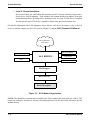
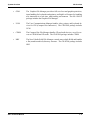
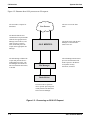
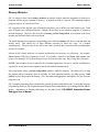
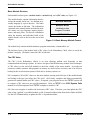
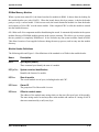
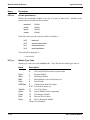
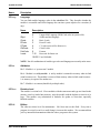
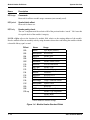
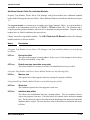
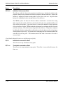
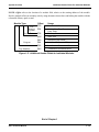
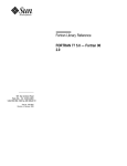
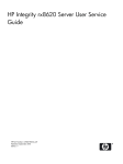
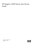
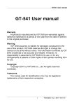
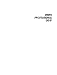
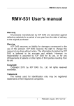
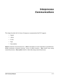
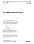
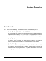
System Overview
System Modularity
OS-9® has four levels of modularity. These are described below and illustrated in Figure 1-1.
•
Level 1 - The Kernel, the Clock, and the Init Modules
The Kernel provides basic system services including Input/Output (I/O) management, process
control, and resource management. The Clock module is a software handler for the specific
real-time-clock hardware. The Init module is an initialization table the kernel uses during system startup.
•
Level 2 - File Managers
File Managers process I/O requests for similar classes of I/O devices. Refer to the I/O
Overview in this chapter for a list of the File Managers Microware currently supports.
•
Level 3 - Device Drivers
Device Drivers handle the basic physical I/O functions for specific I/O controllers. Standard
OS-9 systems are typically supplied with a disk driver, serial port drivers for terminals and
serial printers, and a driver for parallel printers. You can also add customized drivers of your
own design or purchase drivers from a hardware vendor.
OS-9 Technical Manual
1-1
System Modularity
•
System Overview
Level 4 - Device Descriptors
Device Descriptors are small tables that associate specific I/O ports with their logical name,
device driver, and file manager. These modules also contain the physical address of the port
and initialization data. By using device descriptors, only one copy of each driver is required
for each specific type of I/O device, regardless of how many devices the system uses.
For specific information about file managers, device drivers, and device descriptors, refer to the I/O
Overview (in this chapter), the OS-9 I/O System (Chapter 3), and the OS-9 Technical I/O Manual.
User Applications
and Utilities
Math Trap Handlers
Init
OS-9 KERNEL
CIO Library
Clock
User Trap Handlers
File Managers
Device Drivers
Device Descriptors
Figure 1-1: OS-9 Module Organization
NOTE: The shaded boxes contain non-executable code. These modules are referenced, not “called.” The
kernel, file managers, and drivers reference descriptors directly, but only the kernel references the Init
module directly.
1-2
OS-9 Technical Manual
System Overview
System Modularity
An important component, the command interpreter (the Shell), is not shown in the above diagram. The
Shell is an application program, not part of the operating system. It is described fully in Using
Professional OS-9. To obtain a list of the specific modules that make up OS-9 for your system, use the
Ident utility on the OS9Boot file.
Although all modules could be resident in ROM, the system bootstrap module is usually the only ROMed
module in disk-based systems. All other modules are loaded into RAM during system startup.
OS-9 Technical Manual
1-3
I/O Overview
System Overview
I/O Overview
The kernel maintains the I/O system for OS-9. It provides the first level of I/O service by routing system
call requests between processes, and the appropriate file managers and device drivers. Microware includes
the following File Managers in the standard professional distribution:
•
RBF
The Random Block File Manager handles I/O for random-access, block-structured devices, such as floppy/hard disk systems.
•
SCF
The Sequential Character File Manager handles I/O for sequentially characterstructured devices, such as terminals, printers, and modems.
•
SBF
The Sequential Block File Manager handles I/O for sequentially block-structured devices, such as tape systems.
•
PIPEMAN
The Pipe File Manager supports interprocess communications through memory
buffers called pipes.
For specific information about the above file managers, refer to the OS-9 I/O System (Chapter 4) or the
OS-9 Technical I/O Manual.
Microware also supports the following File Managers which are not included in the standard professional
distribution:
1-4
•
PCF
PC File Manager handles reading/writing PC-DOS disks. It uses RBF drivers
and is sold separately.
•
NFM
Network File Manager processes data requests over the OS-9 network. The OS9/NFM package includes NFM.
•
ENPMAN
ENP10 Socket File Manager transfers requests to and from CMC ENP10
boards. OS-9/ESP, the Ethernet Support Package, includes NPMAN.
•
SOCKMAN
Socket File Manager creates and manages the interface to communication protocols (sockets). OS-9/ISP, the Internet Support Package, includes SOCKMAN.
•
IFMAN
Communications Interface File Manager manages network interfaces. OS-9/
ISP, the Internet Support Package, includes IFMAN.
•
PKMAN
Pseudo-Keyboard File Manager provides an interface to the driver side of SCF
to enable the software to emulate a terminal. OS-9/ESP and OS-9/ISP Packages
include PKMAN.
OS-9 Technical Manual
System Overview
I/O Overview
•
GFM
The Graphics File Manager provides a full set of text and graphics primitives,
input handling for keyboards and pointers, and high level features for handling
user interaction in a real time, multi-tasking environment. The OS-9 RAVE
package includes the Graphics File Manager.
•
UCM
The User Communications Manager handles video, pointer, and keyboard devices for CDI (Compact Disc Interactive). The CD-RTOS package includes
UCM.
•
CDFM
The Compact Disc File Manager handles CD and audio devices, as well as access to CD ROM and CD audio. The CD-RTOS package includes CDFM.
•
NRF
The Non-Volatile RAM File Manager controls non-volatile RAM and handles
a flat (non-hierarchical) directory structure. The CD-RTOS package includes
NRF.
OS-9 Technical Manual
1-5
I/O Overview
System Overview
Figure 1-2 illustrates how OS-9 processes an I/O request:
The user makes a request for
data/status.
User Process
The Kernel identifies and
validates the I/O request and the
identifies the appropriate File
Manager, Device Driver, and
other necessary resources.
Then, the Kernel passes the
request to the appropriate File
Manager.
The File Manager validates the
request and performs deviceindependent processing. The
File Manager calls the Device
Driver for hardware interaction,
as needed.
OS-9 KERNEL
File Manager
The user receives the data/
status.
The Kernel works with the File
Manager to return the data/
status to the user.
The File Manager monitors and
processes the data/status and
makes requests to the Kernel
for dynamic memory
allocation, as needed.
Device Driver
The Device Driver performs
device-specific processing and
usually transfers the data/status
back to the File Manager.
Figure 1-2: Processing an OS-9 I/O Request
1-6
OS-9 Technical Manual
System Overview
Memory Modules
Memory Modules
OS-9 is unique in that it uses memory modules to manage both the physical assignment of memory to
programs and the logical contents of memory. A memory module is a logical, self-contained program,
program segment, or collection of data.
OS-9 supports ten pre-defined types of modules and allows you to define your own module types. Each
type of module has a different function. Modules do not have to be complete programs or written in
machine language. However, they must be re-entrant, position-independent, and conform to the basic
module structure described in the next section.
The 68000 instruction set supports a programming style called re-entrant code, that is, code that does not
modify itself. This allows two or more different processes to share one “copy” of a module
simultaneously. The processes do not affect each other, provided that each process has an independent
area for its variables.
Almost all OS-9 family software is re-entrant, and therefore uses memory very efficiently. For example,
Scred requires 26K bytes of memory to load. If you make a request to run Scred while another user
(process) is running it, OS-9 allows both processes to share the same copy, thus saving 26K of memory.
NOTE: Data modules are an exception to the re-entrant requirement. However, careful coordination is
required for several processes to update a shared data module simultaneously.
It does not matter where a position-independent module is loaded in memory. This allows OS-9 to load
the program wherever memory space is available. In many operating systems, you must specify a load
address to place the program in memory. OS-9 determines an appropriate load address for you when the
program is run.
OS-9 compilers and interpreters automatically generate position-independent code. In assembly language
programming, however, the programmer must insure position-independence by avoiding absolute address
modes. Alternatives to absolute addressing are described in the OS-9/68000 Assembler/Linker/
Debugger User’s Manual.
OS-9 Technical Manual
1-7
Basic Module Structure
System Overview
Basic Module Structure
Each module has three parts: a module header, a module body, and a CRC value (see Figure 1-3).
The module header contains information that describes the module and its use. It is defined in assembly language by a psect directive. The linker
creates the header at link-time. The information
contained in the module header includes the module’s name, size, type, language, memory requirements, and entry point. For specific information
about the structure and individual fields of the
module header, refer to the list at the end of this
chapter.
MODULE HEADER
MODULE BODY
Initialization data
Program/Constants
CRC VALUE
Figure 1-3: Basic Memory Module Format
The module body contains initialization data, program instructions, constant tables, etc.
The last three bytes of the module hold a CRC value (Cyclic Redundancy Check value) to verify the
module’s integrity. The linker creates the CRC at link-time.
The CRC Value
The CRC (Cyclic Redundancy Check) is an error checking method used frequently in data
communications and storage systems. It is also a vital part of the ROM memory module search technique.
A CRC value is at the end of all modules to check the validity of the entire module. It provides an
extremely reliable assurance that programs in memory are intact before execution, and is an effective
backup for the error detection systems of disk drives, memory systems, etc.
OS-9 computes a 24-bit CRC value over the entire module, starting at the first byte of the module header
and ending at the byte just before the CRC itself. OS-9 family compilers and linkers automatically
generate the module header and CRC values. If required, your program can use the F$CRC system call
to compute a CRC value over any specified databytes. Refer to F$CRC in the OS-9 System Calls
manual for a full description of how F$CRC computes a module’s CRC.
OS-9 does not recognize a module with an incorrect CRC value. Therefore, you must update the CRC
value of any “patched” or modified module, or OS-9 cannot load the module from disk or find it in ROM.
Use the OS-9 Fixmod utility to update the CRC’s of patched modules.
1-8
OS-9 Technical Manual
System Overview
ROMed Memory Modules
ROMed Memory Modules
When a system reset starts OS-9, the kernel searches for modules in ROM. It detects them by looking for
the module header sync code ($4AFC). When the kernel detects this byte pattern, it checks the header
parity to verify a correct header. If this test succeeds, the kernel obtains the module size from the header
and computes a 24-bit CRC over the entire module. If the computed CRC is valid, the module is entered
into the module directory.
OS-9 links to all of its component modules found during the search. It automatically includes in the system
module directory all ROMed modules present in the system at startup. This allows you to create systems
that are partially or completely ROM-based. It also includes any non-system modules found in ROM.
This allows location of user-supplied software during the start-up process, and its entry into the module
directory.
Module Header Definitions
The following table and Figure 1-4 list definitions of the standard set of fields in the module header.
Name
Description
M$ID
Sync bytes ($4AFC)
These constant bytes identify the start of a module.
M$SysRev
System revision identification
Identifies the format of a module.
M$Size
Size of module
The overall module size in bytes, including header and CRC.
M$Owner
Owner ID
The group/user ID of the module’s owner.
M$Name
Offset to module name
The address of the module name string relative to the start (first sync byte) of the module.
The name string can be located anywhere in the module and consists of a string of ASCII
characters terminated by a null (zero) byte.
OS-9 Technical Manual
1-9
Module Header Definitions
System Overview
Name
Description
M$Accs
Access permissions
Defines the permissible module access by its owner or other users. Module access
permissions are divided into four sections:
reserved
public
group
owner
(4 bits)
(4 bits)
(4 bits)
(4 bits)
Each of the non-reserved permission fields is defined as:
bit 3
bit 2
bit 1
bit 0
reserved
execute permission
write permission
read permission
The total field is displayed as:
-----ewr-ewr-ewr
M$Type
Module Type Code
Module type values are in the oskdefs.d file. They describe the module type code as:
Name
Prgm
Sbrtn
Multi
Data
CSDData
TrapLib
Systm
Flmgr
Drivr
Devic
1 - 10
Description
0
1
2
3
4
5
6-10
11
12
13
14
15
16-up
Not Used (Wild Card value in system calls)
Program Module
Subroutine Module
Multi-Module (reserved for future use)
Data Module
Configuration Status Descriptor
Reserved for future use
User Trap Library
System Module (OS-9 component)
File Manager Module
Physical Device Driver
Device Descriptor Module
User Definable
OS-9 Technical Manual
System Overview
Module Header Definitions
Name
Description
M$Lang
Language
You can find module language codes in the oskdefs.d file. They describe whether the
module is executable and which language the run-time system requires for execution (if
any):
Name
Description
Objct
ICode
PCode
CCode
CblCode
FrtnCode
I-code
0
1
2
3
4
5
6
7-15
16-255
Unspecified Language (Wild Card value in system calls)
68000 machine language
Basic I-code
Pascal P-code
C I-code (reserved for future use)
Cobol I-code
Fortran
Reserved for future use
User Definable
NOTE: Not all combinations of module type codes and languages necessarily make sense.
M$Attr
Attributes
Bit 5 - Module is a “system state” module.
Bit 6 - Module is a sticky module. A sticky module is retained in memory when its link
count becomes zero. The module is removed from memory when its link count becomes 1 or memory is required for another use.
Bit 7 - Module is re-entrant (sharable by multiple tasks).
M$Revs
Revision level
The module’s revision level. If two modules with the same name and type are found in the
memory search or loaded into memory, only the module with the highest revision level is
kept. This enables easy substitution of modules for update or correction, especially
ROMed modules.
M$Edit
Edition
The software release level for maintenance. OS-9 does not use this field. Every time a
program is revised (even for a small change), increase this number. We recommend that
you key internal documentation within the source program to this system.
OS-9 Technical Manual
1 - 11
Module Header Definitions
System Overview
Name
Description
M$Usage
Comments
Reserved for offset to module usage comments (not currently used).
M$Symbol
Symbol table offset
Reserved for future use.
M$Parity
Header parity check
The one’s complement of the exclusive-OR of the previous header “words.” OS-9 uses this
for a quick check of the module’s integrity.
NOTE: Offset refers to the location of a module field, relative to the starting address of the module.
Resolve module offsets in assembly code by using the names shown here and linking the module with the
relocatable library, sys.l or usr.l.
Offset
Name
$00
$02
$04
$08
$0C
$10
$12
$13
$14
$15
$16
$18
$1C
$20
$2E
$30-up
M$ID
M$SysRev
M$Size
M$Owner
M$Name
M$Accs
M$Type
M$Lang
M$Attr
M$Revs
M$Edit
M$Usage
M$Symbol
M$Parity
Usage
Sync Bytes ($4AFC)
Revision ID
Module Size
Owner ID
Module Name Offset*
Access Permissions
Module Type
Module Language
Attributes
Revision Level
Edit Edition
Usage Comments Offset*
Symbol Table
Reserved
Header Parity Check
Module Type Dependent
Module Body
CRC Check
* These fields are offset to strings
Figure 1-4: Module Header Standard Fields
1 - 12
OS-9 Technical Manual
System Overview
Additional Header Fields For Individual Modules
Additional Header Fields For Individual Modules
Program, Trap Handler, Device Driver, File Manager, and System modules have additional standard
header fields following the universal offsets. These additional fields are listed below and shown in Figure
1-5.
The program module is a common type of module (type: Prgm; language: Objct). A program module is
executable as an independent process by the F$Fork or F$Chain system calls. The assembler and C
compilers produce program modules, and most OS-9 commands are program modules. Program module
headers have six fields in addition to the universal set.
Chapter 4 describes trap handler modules. The OS-9 Technical I/O Manual describes File Manager
modules and Device Drivers modules.
Name
Description
(Program, Trap Handler, Device Driver, File Manager, and System Module Headers use the following
two fields.)
M$Exec
Execution offset
The offset to the program’s starting address. In the case of a file manager or driver, this is
the offset to the module’s entry table.
M$Excpt
Default user trap execution entry point
The relative address of a routine to execute if an uninitialized user trap is called.
(Program, Trap Handler, and Device Driver Module Headers use the following field.)
M$Mem
Memory size
The required size of the program’s data area (storage for program variables).
(Program and Trap Handler Module Headers use the following three fields.)
M$Stack
Stack size
The minimum required size of the program’s stack area.
M$IData
Initialized data offset
The offset to the initialization data area’s starting address. This area contains values to
copy to the program’s data area. The linker places all constant values declared in vsects
here. The first four-byte value is the offset from the beginning of the data area to which the
initialized data is copied. The next four-byte value is the number of initialized data-bytes
to follow.
OS-9 Technical Manual
1 - 13
Additional Header Fields For Individual Modules
System Overview
Name
Description
M$IRefs
Initialized references offset
The offset to a table of values to locate pointers in the data area. Initialized variables in the
program’s data area may contain values that are pointers to absolute addresses. Adjust code
pointers by adding the absolute starting address of the object code area. Adjust the data
pointers by adding the absolute starting address of the data area.
The F$Fork system call does the effective address calculation at execution time using
tables created in the module. The first word of each table is the most significant (MS) word
of the offset to the pointer. The second word is a count of the number of least significant
(LS) word offsets to adjust. F$Fork makes the adjustment by combining the MS word with
each LS word entry. This offset locates the pointer in the data area. The pointer is adjusted
by adding the absolute starting address of the object code or the data area (for code pointers
or data pointers respectively). It is possible after exhausting this first count that another MS
word and LS word are given. This continues until a MS word of zero and a LS word of
zero are found.
(Trap Handler Module Headers use the following two fields.)
M$Init
Initialization execution offset
The offset to the trap initialization entry point.
M$Term
Termination execution offset
The offset to the trap termination entry point. This offset is reserved by Microware for
future use.
1 - 14
OS-9 Technical Manual
System Overview
Additional Header Fields For Individual Modules
NOTE: Offset refers to the location of a module field, relative to the starting address of the module.
Resolve module offsets in assembly code by using the names shown here and linking the module with the
relocatable library: sys.l or usr.l.
Module Type:
File
Manager
/System
Device Driver
Program
Trap Handlers
Offset
$30
$34
$38
$3C
$40
$44
$48
$4C
Usage
Execution Offset
Default User Trap Execution
Entry Point
Memory Size
Stack Size
Initialized Data Offset
Initialized Reference Offset
Initialization Execution Offset
Termination Execution Offset
Figure 1-5: Additional Header Fields for Individual Modules
End of Chapter 1
OS-9 Technical Manual
1 - 15