1
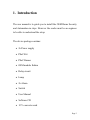
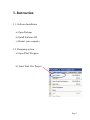
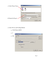
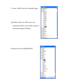
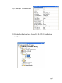
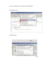
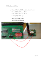
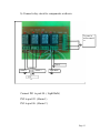
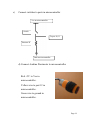
User Manual Page 1 Table of Contents 1. Introduction ...................................................3 2. Overview .......................................................4 2.1 Functional Description ..........................................4 2.2 Cautions and Warnings .........................................4 3. Instruction Sections .......................................5 3.1 Software Installation .............................................5 3.2 Designing System…..............................................5 3.3 Hardware Installation ..........................................12 4. Running the Project…..................................15 5. Error & Solution…………….......................15 Page 2 1. Introduction The user manual is to guide you to install the GSM Home Security and Automation in steps. However the reader must be an engineer to be able to understand the setup. The device package contains: 2x Power supply PSoC Kit PSoC Burner GSM module Enfora Relay circuit Lamp 2x Alarm Switch User Manual Software CD 12 V converter card Page 3 2. Overview 2.1. Functional Description This installation will allow you to secure your house from burglars by trigging alarms and indicating to you there is a burglar in the house. As well it allows you to control any appliance in your house. 2.2. Cautions and Warnings This project deals with AC electricity which is dangerous. You must treat electricity with caution. There are many books and websites about electrical safety procedures and if you’re not sure how to be safe you should read that any book first. Be careful when using PSoC kit with power supply. Avoid changing connection in the kit with power supply on. Page 4 3. Instruction 3.1. Software Installation a) Open Package b) Install Software CD c) Restart your computer 3.2. Designing system a) Open PSoC Designer b) Select Start New Project Page 5 c) Select Project Type d) Name the Project e) Select Device and Coding Method CY8C29666-24PXI C OK Page 6 f) Select UART from User Module Pages g) Double Click on UART wait a few moments until the user module is placed in the Interconnect Window. h) Repeat same for Digital Buffer Page 7 i) When you are done the screen should look like this j) Configure Global Resources Page 8 k) Configure User Modules l) Create Application Code located to the left of application window. Page 9 m) You can find the code in the CD called Main.C n) Compile main.c o) Build project Page 10 p) Program the device by selecting MINIProg in port window. Select Connect Select Program When program is complete toggle Device Power Page 11 3.3 Hardware Installation a) Connect PSoC and GSM module as shown below. Vcc on GSM with Vcc on PSoC. Gnd on GSM with Gnd on PSoC Port 14 (P14) with Rx pin Port 17 (P17) with Tx pin Port 16 P16) with Ring pin Page 12 b) Connect relay circuit to components as shown To ports in microcontroll er 220 V Alarm 1 Alarm 2 Light Bulb 12 V Connect IN1 to port 04. ( Light Bulb) IN2 to port 05. (Alarm 1) IN3 to port 06. (Alarm 2 ) Page 13 c) Connect switches to ports in microcontroller Vcc in microcontroller Switch To port 10,11 Resistor 5k Gnd in microcontroller d) Connect Audrino Proximeter to microcontroller Red +5V to Vcc in microcontroller. Yellow wire to port 12 in microcontroller. Green wire to ground in microcontroller. Page 14 4. Running the Project a) Insert Sim Card inside the GSM module. b) Turn on the power supply. c) Send a message to the number of Sim Card. d) Body of message a. 111 ( To turn light on.) b. 000 ( To turn light off.) c. 333 ( To turn alarm on.) d. 222 ( To turn alarm off.) 5. Error & Solution If there is no response when any action is taken press the reset button found on the PSoC. Page 15