1
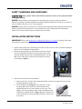
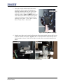
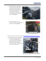
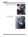
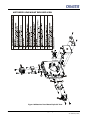
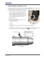
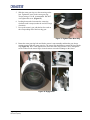
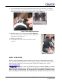
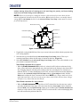
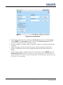
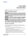
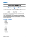
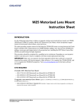
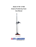
Upgrading a Non-motorized Lens Mount
Instruction Sheet
INTRODUCTION
Use the following instructions when upgrading an existing non-motorized lens mount on CP2220
(127-002103-xx) and CP2230 (127-003104-xx) projectors with the Motor Upgrade Kit, which
incorporates stepper motors for horizontal/vertical offsets, zoom and focus.
The entire procedure requires mounting Focus, X and Y axis motors, sensor flags, adding a zoom gear
and stepper motor to the projection lens, installing the Motor Control Assembly, and performing
boresight alignment.
This procedure should be completed by a qualified service technician. The entire procedure can take
up to 1 hour to complete.
IMPORTANT: Make sure your projector has been upgraded with the latest software to ensure the
motorized lens mount will function properly. Visit www.christiedigital.com for the latest software
downloads.
KITS REQUIRED
• 127-102104-xx Motor Upgrade Kit
TOOLS REQUIRED
• #1, #2 Phillips screwdrivers, and a small flathead screwdriver
• 3 & 5 mm hex keys
• 13mm ratchet
Upgrading a Non-motorized Lens Mount Instruction Sheet
020-100471-01 (02-2010)
1 of 12
SAFETY WARNINGS AND GUIDELINES
Always power down and disconnect all power sources to the projector before
servicing or cleaning.
NOTICE: When adjusting a non-motorized or motorized lens mount on a projector that has a
Motorized Auxiliary Lens Mount (MALM), swing the MALM completely out of the way to ensure it
does not collide with the lens as it is being adjusted.
NOTICE: Always perform a Lens Reset (in software) after adjusting the Horizontal and Vertical offset
knobs to bring the lens mount back to a zero position before proceeding with other adjustments.
Failure to do so may limit the range of motion of the lens mount.
INSTALLATION INSTRUCTIONS
IMPORTANT: Refer to the Motorized Lens Mount Exploded View on page 6 to identify all the parts
and hardware required for upgrading a non-motorized lens mount.
1. Remove the projection lens from the projector and set aside in an area where it cannot be damaged.
Refer to the User Manual for instructions.
2. Install two ground straps, provided in the kit, between each of
the lens mount plates. Install one from the first to the second
plate and another between the second and third plates. Use the
M4 screws with captive washers and lock washers provided
for mounting. (Figure 1)
Figure 1 Install Ground Straps
3. Install Focus and Offset motor assemblies:
a. Remove the focus, X and Y offset adjustment knobs from the lens mount. Keep focus knob
mounting hardware for later use.
b. Insert an adapter shaft (Figure 2) into each of the vacant
mounting holes from which the vertical and horizontal
adjustment knobs were removed in the previous step. This
adapter resizes the opening to allow for the installation of the
offset motor assembly. Refer to Figure 10 for an exploded view
of the motorized lens mount assembly and where various parts
are located.
Figure 2 Adapter Shaft
2 of 12
Upgrading a Non-motorized Lens Mount Instruction Sheet
020-100471-01 (02-2010)
c. Secure the vertical and horizontal offset motor
assemblies to the lens mount by inserting and
tightening a threaded rod into each. Then secure
each offset motor bracket with two M6 screws
with lock washers. (Figure 3) NOTE: Motors are
color coded (with a label on the body) for ease of
connection with motor control harnesses. When
installing ensure Yellow = Focus, Red = Vertical,
Black = Zoom, White = Horizontal.
Figure 3 Securing Motor Assembly
d. Install a sensor flag to each vertical and horizontal offset motor assembly using two M3 screws
(with lock washers) and washers. (Figure 4) Do a visual inspection to ensure the flag moves
freely through the sensor. Failure for the flag to clear the sensor can result in damage to the
sensor.
Figure 4 Offset Sensor Flag
Upgrading a Non-motorized Lens Mount Instruction Sheet
020-100471-01 (02-2010)
3 of 12
e. Install the focus motor assembly to
the front of the lens mount reusing
two M4 screws with washers that
originally mounted the manual focus
adjustment knob. Install the focus
sensor assembly and the focus
sensor flag to the front of the lens
mount. Requires two M3 screws and
washer each. (Figure 5)
Figure 5 Secure Focus Sensor Flag
f. Install a metal safety cover over
each motor assembly using two M4 screws
and washers for each. (Figure 6)
Figure 6 Install Safety Cover
4. Install zoom motor to projection lens. Refer to Mount Zoom Motor Assembly to Lens on page 7.
5. Install the Motor Control Assembly (MCA).
a. Connect harnesses from each stepper
motor to their designated inline
connector from the MCA. Harnesses
and motors are color coded (with
labels) to make connection easier.
Yellow = Focus, Red = Vertical, Black
= Zoom, White = Horizontal
Figure 7 Color Coding of Harnesses and Motors
4 of 12
Upgrading a Non-motorized Lens Mount Instruction Sheet
020-100471-01 (02-2010)
b. The MCA cover uses keyhole slots so that it can
be slipped over the hex head cap screws on the
lens mount - closest to the horizontal motor.
(Figure 8)
Figure 8 Install MCA
c. Connect the power harness from the
MCA to the connector port on the
projector as shown in Figure 9.
Figure 9 Connect MCA
Upgrading a Non-motorized Lens Mount Instruction Sheet
020-100471-01 (02-2010)
5 of 12
MOTORIZED LENS MOUNT EXPLODED VIEW
Figure 10 Motorized Lens Mount Exploded View
6 of 12
Upgrading a Non-motorized Lens Mount Instruction Sheet
020-100471-01 (02-2010)
MOUNT ZOOM MOTOR ASSEMBLY TO LENS
Use the following procedure to install the Zoom Motor Assembly (Figure 11) to the lens you will be
using with the projector. This procedure applies to any of the available lenses for your projector model.
1. Attach the zoom motor assembly to the lens. Ensure the
center of the motor is aligned with the top of the lens
(use UP label as reference) and that the adjustment
screw on the clamp is positioned on the left side of the
UP label (see Figure 11). TIP: Ensure there is no interference between the screw clamp and the MCA enclosure by installing the lens once the zoom motor
assembly is attached.
2. Adjust the position of lens:
• Position the following lenses against the front of the
motor mount (see Figure 12):
> 1.6-2.4
Figure 11 Zoom Motor
> 1.8-3.0
and Clamp
> 2.15-3.6
• Position the following lens against the back of the motor mount (see Figure 13):
> 1.45-2.5
For all other lenses, adjust the position of the lens so that a small gap is left between the lens zoom
ring and the motor mount to prevent rubbing and deterioration of the two components.
Figure 12
Upgrading a Non-motorized Lens Mount Instruction Sheet
020-100471-01 (02-2010)
7 of 12
Figure 13
3. Use a 3 mm hex driver to tighten the clamp around the lens - Torque setting of 1 in-lb.
recommended.
4. Install the zoom gear ring and
zoom gear spacer suited for
your lens type. Spacers snap
into the grooves on the ring.
(Figure 14)
• Use the small adapter with
the 1.8-3.0 lens.
• Use the larger adapter with
the 1.45-2.05, and 2.15-3.6
lenses.
• No adapter required for other
lenses.
Figure 14 Zoom Ring and Zoom Gear Spacer
8 of 12
Upgrading a Non-motorized Lens Mount Instruction Sheet
020-100471-01 (02-2010)
5. Slide the zoom gear ring over the zoom ring on the
lens. Tighten the screw on the zoom gear ring Torque setting of 3 in-lb. recommended. DO NOT
over-tighten this screw. (Figure 15)
6. Looking down at the lens rotate the zoom ring
clockwise until it stops (reaches the end of its range
of motion).
7. Line up the motor’s gear with the last few teeth on
the corresponding end of the lens ring gear.
Figure 15 Tighten Zoom Gear Ring
8. Rotate the zoom gear ring back and forth to ensure it runs smoothly and that the gear always
remains engaged with the zoom gear ring. The sensor flag should always remain in line with the
ring (Figure 16). Do a visual inspection to ensure the sensor flag will move freely through the
sensor. Failure for the sensor flag to clear the sensor can result in damage to the sensor.
Figure 16 Engage Gear
Upgrading a Non-motorized Lens Mount Instruction Sheet
020-100471-01 (02-2010)
9 of 12
9. To prevent premature wear of the gear motor and zoom gear ring, check if there is a small gap
between the teeth of these parts. If fine tuning is required, loosen the screw on the gear motor in
small increments until a small gap between the teeth is evident. (Figure 17)
Figure 17 Fine Tuning Gear Position
10. Install the safety cover over the motor assembly (Figure 18).
Note: The harness on the sensor may need to be carefully bent
back a little to install the cover.
11. Install the projection lens.
12. Connect the harness from the lens to the Motor Control
Assembly.
Figure 18 Safety Cover
BASIC OPERATION
Before you begin operating the projector with the new lens mount, it is important that you perform
some basic optical alignment procedures to achieve optimized images on the screen. Refer to the User
Manual for more information on lens control options. Updated User Manuals can be found at
www.christiedigital.com.
1) If present, move the Motorized Auxiliary Lens Mount (MALM) to the OUT
position before performing any lens calibrate or reset functions on the Motorized Primary Lens
Mount to prevent collision between the projection lens and the MALM. 2) Hazardous moving
parts. Keep fingers and other body parts away. Remotely operated motors may start to spin
10 of 12
Upgrading a Non-motorized Lens Mount Instruction Sheet
020-100471-01 (02-2010)
without warning. Keep clear of rotating parts and avoid long hair, jewelry, and loose clothing
exposure to the knobs during manual adjustment.
NOTES: 1) In case of emergency, unplug the interface cable at the top left corner above the lens
mount to immediately halt movement of the lens mount. 2) Only Advanced users can modify channel
settings. 2) The ILS Installed check box in the Advanced Setup: Lens Setup window must be selected
for all ILS adjustments.
Motorized Vertical Offset
Vertical Offset Knob
Motorized Zoom
Horizontal Boresight Bolt
Anchor Bolt
Horizontal Offset Knob
Lock/Unlock Lens
Focus
Vertical Boresight
Motorized Horizontal Offset
Figure 1-19 Anatomy of the Lens Mount
1. If applicable, swing the MALM out of the way to ensure it does not collide with the projection lens
as it is being adjusted.
2. Select the lens type installed from the Advanced Setup: Lens Setup window. This step is
extremely important to allow the full range of motion for that lens. (Figure 20)
3. Select ILS Installed from the Advanced Setup: Lens Setup window. Then select whether or not
you want the Automatic ILS feature.
When Enable Automatic ILS is selected
• When the Enable Automatic ILS check box is selected, the ILS adjusts each motor for the
focus, offset, and zoom to automatically move the lens based on the settings in the selected ILS
file. Changing channels will change the position of the lens, assuming the new channel uses a
different ILS file. To make adjustments to an ILS file, use the motorized lens mount adjustment
features in the Advanced Setup: ILS File Setup window or Lens Adjust window from the
Main panel to adjust the focus, zoom and offset values. NOTE: Any changes made to the focus,
offset and zoom values will overwrite the current values in the ILS file, therefore these changes
will affect every channel that uses this ILS file.
When Enable Automatic ILS is not selected
• When the Enable Automatic ILS check box is NOT selected, the lens does not move unless
you make adjustments to the focus, offset and zoom from the Lens Adjust window launched
from the Main panel (the ILS File Setup window is not available when the Enable Automatic ILS
check box is not selected). These settings will NOT overwrite the ILS values and changing channels will not affect the position of the lens.
Upgrading a Non-motorized Lens Mount Instruction Sheet
020-100471-01 (02-2010)
11 of 12
Figure 20 Lens Setup Window
4. Electronically calibrate the lens, by clicking the Full Calibration button also in the Lens Setup
window. NOTE: If the Full Calibration button is selected when Enable Automatic ILS is NOT
selected, the lens will return to the remembered setting.
5. Once lens calibration is complete, display a “framing” test pattern or something equivalent with
crosshairs.
6. Adjust boresight to ensure the lens and lens mount are precisely adjusted in relation to the
projector’s internal optics. Refer to the boresight instructions provided in the product User
Manual.
7. After boresight is complete, configure the lens for each channel as required. NOTE: Ensure the
Enable Automatic ILS checkbox is selected to over-write settings for the selected channel. If
Enable Automatic ILS is NOT selected then changes made to lens settings are temporary and will
be lost once it is selected again.
12 of 12
Upgrading a Non-motorized Lens Mount Instruction Sheet
020-100471-01 (02-2010)