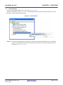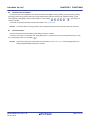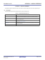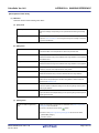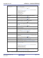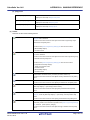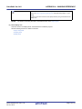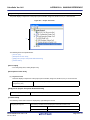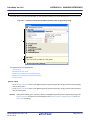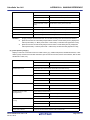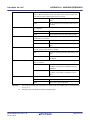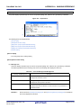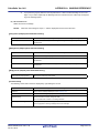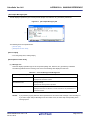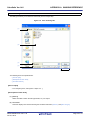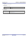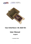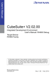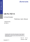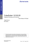
1
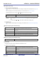
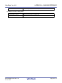
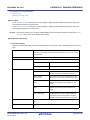
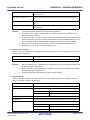
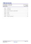
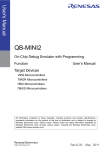
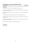
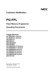
User’s Manual
CubeSuite Ver.1.40
Integrated Development Environment
User’s Manual: Programming
Target Device
78K0 Microcontroller
78K0R Microcontroller
V850 Microcontroller
All information contained in these materials, including products and product specifications,
represents information on the product at the time of publication and is subject to change by
Renesas Electronics Corp. without notice. Please review the latest information published by
Renesas Electronics Corp. through various means, including the Renesas Electronics Corp.
website (http://www.renesas.com).
www.renesas.com
Rev.1.00
Oct 2010
Notice
1.
2.
3.
4.
5.
6.
7.
All information included in this document is current as of the date this document is issued. Such information, however, is
subject to change without any prior notice. Before purchasing or using any Renesas Electronics products listed herein, please
confirm the latest product information with a Renesas Electronics sales office. Also, please pay regular and careful attention to
additional and different information to be disclosed by Renesas Electronics such as that disclosed through our website.
Renesas Electronics does not assume any liability for infringement of patents, copyrights, or other intellectual property rights
of third parties by or arising from the use of Renesas Electronics products or technical information described in this document.
No license, express, implied or otherwise, is granted hereby under any patents, copyrights or other intellectual property rights
of Renesas Electronics or others.
You should not alter, modify, copy, or otherwise misappropriate any Renesas Electronics product, whether in whole or in part.
Descriptions of circuits, software and other related information in this document are provided only to illustrate the operation of
semiconductor products and application examples. You are fully responsible for the incorporation of these circuits, software,
and information in the design of your equipment. Renesas Electronics assumes no responsibility for any losses incurred by
you or third parties arising from the use of these circuits, software, or information.
When exporting the products or technology described in this document, you should comply with the applicable export control
laws and regulations and follow the procedures required by such laws and regulations. You should not use Renesas
Electronics products or the technology described in this document for any purpose relating to military applications or use by
the military, including but not limited to the development of weapons of mass destruction. Renesas Electronics products and
technology may not be used for or incorporated into any products or systems whose manufacture, use, or sale is prohibited
under any applicable domestic or foreign laws or regulations.
Renesas Electronics has used reasonable care in preparing the information included in this document, but Renesas Electronics
does not warrant that such information is error free. Renesas Electronics assumes no liability whatsoever for any damages
incurred by you resulting from errors in or omissions from the information included herein.
Renesas Electronics products are classified according to the following three quality grades: “Standard”, “High Quality”, and
“Specific”. The recommended applications for each Renesas Electronics product depends on the product’s quality grade, as
indicated below. You must check the quality grade of each Renesas Electronics product before using it in a particular
application. You may not use any Renesas Electronics product for any application categorized as “Specific” without the prior
written consent of Renesas Electronics. Further, you may not use any Renesas Electronics product for any application for
which it is not intended without the prior written consent of Renesas Electronics. Renesas Electronics shall not be in any way
liable for any damages or losses incurred by you or third parties arising from the use of any Renesas Electronics product for an
application categorized as “Specific” or for which the product is not intended where you have failed to obtain the prior written
consent of Renesas Electronics. The quality grade of each Renesas Electronics product is “Standard” unless otherwise
expressly specified in a Renesas Electronics data sheets or data books, etc.
“Standard”:
8.
9.
10.
11.
12.
Computers; office equipment; communications equipment; test and measurement equipment; audio and visual
equipment; home electronic appliances; machine tools; personal electronic equipment; and industrial robots.
“High Quality”: Transportation equipment (automobiles, trains, ships, etc.); traffic control systems; anti-disaster systems; anticrime systems; safety equipment; and medical equipment not specifically designed for life support.
“Specific”:
Aircraft; aerospace equipment; submersible repeaters; nuclear reactor control systems; medical equipment or
systems for life support (e.g. artificial life support devices or systems), surgical implantations, or healthcare
intervention (e.g. excision, etc.), and any other applications or purposes that pose a direct threat to human life.
You should use the Renesas Electronics products described in this document within the range specified by Renesas Electronics,
especially with respect to the maximum rating, operating supply voltage range, movement power voltage range, heat radiation
characteristics, installation and other product characteristics. Renesas Electronics shall have no liability for malfunctions or
damages arising out of the use of Renesas Electronics products beyond such specified ranges.
Although Renesas Electronics endeavors to improve the quality and reliability of its products, semiconductor products have
specific characteristics such as the occurrence of failure at a certain rate and malfunctions under certain use conditions. Further,
Renesas Electronics products are not subject to radiation resistance design. Please be sure to implement safety measures to
guard them against the possibility of physical injury, and injury or damage caused by fire in the event of the failure of a
Renesas Electronics product, such as safety design for hardware and software including but not limited to redundancy, fire
control and malfunction prevention, appropriate treatment for aging degradation or any other appropriate measures. Because
the evaluation of microcomputer software alone is very difficult, please evaluate the safety of the final products or system
manufactured by you.
Please contact a Renesas Electronics sales office for details as to environmental matters such as the environmental
compatibility of each Renesas Electronics product. Please use Renesas Electronics products in compliance with all applicable
laws and regulations that regulate the inclusion or use of controlled substances, including without limitation, the EU RoHS
Directive. Renesas Electronics assumes no liability for damages or losses occurring as a result of your noncompliance with
applicable laws and regulations.
This document may not be reproduced or duplicated, in any form, in whole or in part, without prior written consent of Renesas
Electronics.
Please contact a Renesas Electronics sales office if you have any questions regarding the information contained in this
document or Renesas Electronics products, or if you have any other inquiries.
(Note 1) “Renesas Electronics” as used in this document means Renesas Electronics Corporation and also includes its majorityowned subsidiaries.
(Note 2) “Renesas Electronics product(s)” means any product developed or manufactured by or for Renesas Electronics.
How to Use This Manual
This manual describes the role of the CubeSuite integrated development environment for developing applications
and systems for 78K0 microcontrollers, 78K0R microcontrollers and V850 microcontrollers, and provides an outline
of its features.
CubeSuite is an integrated development environment (IDE) for 78K0 microcontrollers, 78K0R microcontrollers and
V850 microcontrollers, integrating the necessary tools for the development phase of software (e.g. design,
implementation, and debugging) into a single platform.
By providing an integrated environment, it is possible to perform all development using just this product, without
the need to use many different tools separately.
Readers
This manual is intended for users who wish to understand the functions of the
CubeSuite and design software and hardware application systems.
Purpose
This manual is intended to give users an understanding of the functions of the
Cubesuite to use for reference in developing the hardware or software of systems using
these devices.
Organization
This manual can be broadly divided into the following units.
CHAPTER 1 GENERAL
CHAPTER 2 FUNCTIONS
APPENDIX A WINDOW REFERENCE
APPENDIX B INDEX
How to Read This Manual It is assumed that the readers of this manual have general knowledge of electricity, logic
circuits, and microcontrollers.
Conventions
Data significance:
Higher digits on the left and lower digits on the right
–––
Active low representation: XXX (overscore over pin or signal name)
Note:
Footnote for item marked with Note in the text
Caution:
Information requiring particular attention
Remark:
Supplementary information
Numeric representation:
Decimal … XXXX
Hexadecimal … 0xXXXX
Related Documents
The related documents indicated in this publication may include preliminary versions.
However, preliminary versions are not marked as such.
Document Name
Document No.
CubeSuite
Start
Integrated Development Environment
Analysis
R20UT0265E
User's Manual
Programming
This manual
Caution
R20UT0256E
Message
R20UT0267E
Coding for CX compiler
R20UT0259E
Build for CX compiler
R20UT0261E
78K0 Coding
R20UT0004E
78K0 Build
R20UT0005E
78K0 Debug
R20UT0262E
78K0 Design
R20UT0006E
78K0R Coding
U19382E
78K0R Build
U19385E
78K0R Debug
R20UT0263E
78K0R Design
R20UT0007E
V850 Coding
U19383E
V850 Build
U19386E
V850 Debug
R20UT0264E
V850 Design
R20UT0257E
The related documents listed above are subject to change without
notice. Be sure to use the latest edition of each document when
designing.
All trademarks or registered trademarks in this document are the property of their respective
owners.
[MEMO]
[MEMO]
[MEMO]
TABLE OF CONTENTS
CHAPTER 1 GENERAL ... 9
1.1 Overview ... 9
1.2 Features ... 9
CHAPTER 2 FUNCTIONS ... 10
2.1
2.2
2.3
2.4
2.5
2.6
2.7
Overview ... 10
Select Emulator ... 11
Open Property Panel ... 12
Enter Information ... 12
Establish Connection ... 12
Execute Flash Command ... 13
End Connection ... 13
APPENDIX A WINDOW REFERENCE ... 14
A.1 Description ... 14
APPENDIX B INDEX ... 37
CubeSuite Ver.1.40
CHAPTER 1 GENERAL
CHAPTER 1 GENERAL
CubeSuite is an integrated development environment used to carry out tasks such as design, coding, build and debug
for developing application systems for microcontrollers manufactured by Renesas Electronics.
This chapter gives an overview of the flash programming tool (QB-Programmer).
1.1
Overview
The flash programming tool is one of the components provided by CubeSuite. It provides a GUI to set information in the
microcontroller's built-in Flash memory by executing such commands as blank check, erase, program, verify and read.
Remark
The emulator (MINICUBE2 or E1) is needed to execute commands from the flash programming tool. E1 can
only be used when the target device is a V850.
1.2
Features
Below are the features of the flash programming tool.
- Supports microcontrollers with built-in single-power-supply flash memory
- Can communicate with microcontrollers via UART and CSI-H/S
- Can supply 3.3 or 5.0 V power (maximum rated current : 200 mA) to the microcontroller
- Can supply a power to the microcontroller
When using MINICUBE2 :
3.1 V or 5.0 V (maximum rated current : 100 mA)
When using E1 :
3.3 V or 5.0 V (maximum rated current : 200 mA)
- Can supply a 4, 8, or 16 MHz clock to the microcontroller
R20UT0266EJ0100 Rev.1.00
Oct 01, 2010
Page 9 of 41
CubeSuite Ver.1.40
CHAPTER 2 FUNCTIONS
CHAPTER 2 FUNCTIONS
This chapter describes the key functions provided by the flash programming tool along with operation procedures.
2.1
Overview
The flash programming tool can execute such commands as blank check, erase, program, verify and read by selecting/
inputting in the CubeSuite panel the information necessary to manipulate the microcontroller's built-in Flash memory.
The following sections describe the operation procedures for the flash programming tool.
(1) Start CubeSuite
Launch CubeSuite from the [Start] menu of Windows.
Remark
See "CubeSuite Start User's Manual" for details on "Start CubeSuite".
(2) Create/Open project
Create a new project (that defines a kind of project, microcontroller to be used, build tools to be used, etc.) or load
an existing project.
Remark
See "CubeSuite Start User's Manual" for details on "Create/Open project".
(3) Select Emulator
Selct the emulator (MINICUBE2 or E1) to use int the Project Tree panel.
(4) Open Property Panel
Open the Property panel for setting information necessary to manipulate Flash memory.
(5) Enter Information
Set information necessary to manipulate Flash memory in the Property panel.
(6) Establish Connection
Establish a connection between the flash programming tool and the emulator.
(7) Execute Flash Command
Execute Flash commands (e.g. blank check, erase, program, verify and read).
(8) End Connection
End the connection between the flash programming tool and the emulator.
(9) Save project
Save a project.
Remark
See "CubeSuite Start User's Manual" for details on "Save project".
R20UT0266EJ0100 Rev.1.00
Oct 01, 2010
Page 10 of 41
CubeSuite Ver.1.40
2.2
CHAPTER 2 FUNCTIONS
Select Emulator
Selct the emulator (MINICUBE2 or E1) to use int the Project Tree panel.
To select the emulator, from the Project Tree panel select [QB-Programmer (Flash Programming Tool)], then from the
context menu, select [Using Programming Tool].
Figure 2-1. Select Emulator
Remark
If the microcontroller defined for a project is not supported by the flash programming tool (e.g. a ROMless
product), then the [QB-Programmer (Flash Programming Tool)] node will not appear under [Project name
(Project)] in the Project Tree panel.
R20UT0266EJ0100 Rev.1.00
Oct 01, 2010
Page 11 of 41
CubeSuite Ver.1.40
2.3
CHAPTER 2 FUNCTIONS
Open Property Panel
Open the Property panel for setting information necessary to manipulate Flash memory.
To open the Property panel, from the Project Tree panel select [QB-Programmer (Flash Programming Tool)], then from
the context menu, select [Property].
Figure 2-2. Open Property Panel
2.4
Enter Information
In the Property panel opened in "2.3 Open Property Panel", set the information necessary to manipulate Flash memory in the detail information display/change area.
Remarks 1.
The information in the [Target Microcontroller] category appears when the execution of a Flash command from "2.6 Execute Flash Command" completes.
2.
The information in the [MINICUBE2] category appears when a connection with the emulator from "2.5
Establish Connection" is established, and when the connection is ended as in "2.7 End Connection".
2.5
Establish Connection
Establish a connection between the flash programming tool and the emulator.
To establish the connection, from the menu bar, select [Flash] menu >> [Connect to Flash Programming Tool], or click
the corresponding button on the toolbar (
Remarks 1.
).
To execute Flash commands using the flash programming tool, you must establish a connection in
order to exclusively control the emulator, which is shared by multiple components (e.g. the debugging
tool).
2.
When a connection has been established to the emulator, the relevant information (firmware version)
appears on the Property panel, under the [MINICUBE2] category.
R20UT0266EJ0100 Rev.1.00
Oct 01, 2010
Page 12 of 41
CubeSuite Ver.1.40
2.6
CHAPTER 2 FUNCTIONS
Execute Flash Command
On the menu bar, from the [Flash] menu, select the relevant item ([Blank Check], [Erase], [Program], [Verify], [Read],
[Security], [Check Sum], [Autoprocedure (E.P)], [Set Option Bytes], [Set OCD Security ID], [Signature Read], or [Get
Flash Options]). Alternatively, click the relevant button on the toolbar (
,
,
,
,
, or
). The Flash com-
mand is executed.
The results of executing the Flash command are output to the Output panel.
Remark
2.7
Commands that are not supported by microcontrollers with built-in Flash command cannot be executed.
End Connection
End the connection between the flash programming tool and the emulator.
To end the connection, from the menu bar, select [Flash] menu >> [Disconnect from Flash Programming Tool], or click
the corresponding button on the toolbar (
Remark
).
When disconnected from the emulator, the information on the Property panel under the [Target Microcontroller] and [MINICUBE2] categories is cleared.
R20UT0266EJ0100 Rev.1.00
Oct 01, 2010
Page 13 of 41
CubeSuite Ver.1.40
APPENDIX A WINDOW REFERENCE
APPENDIX A WINDOW REFERENCE
This appendix explains in detail the functions of the windows, panels and dialog boxes of the flash programming tool.
A.1
Description
The flash programming tool has the following windows, panels and dialog boxes.
Table A-1. Window/Panel/Dialog Box List
Window/Panel/Dialog Box Name
Main window
Function
This is the first window to open when CubeSuite is launched. This window is used to
operate various components (design tool, build tool, etc.) provided by CubeSuite.
Project Tree panel
This panel displays the components of the project (microcontroller, design tool, build
tool, etc.) in a tree structure.
Property panel
This panel allows you to view the information and change the setting for the node
selected in the Project Tree panel.
Output panel
This panel displays operation logs for various components (design tool, build tool, etc.)
provided by CubeSuite.
Save As dialog box
R20UT0266EJ0100 Rev.1.00
Oct 01, 2010
This dialog box allows you to name and save a file (such as a report file).
Page 14 of 41
CubeSuite Ver.1.40
APPENDIX A WINDOW REFERENCE
Main window
This is the first window to open when CubeSuite is launched. This window is used to operate various components
(design tool, build tool, etc.) provided by CubeSuite.
Figure A-1. Main Window
(1)
(2)
(3)
The following items are explained here.
- [How to open]
- [Description of each area]
[How to open]
- From the [start] menu, select [All Programs] >> [NEC Electronics CubeSuite] >>[CubeSuite].
R20UT0266EJ0100 Rev.1.00
Oct 01, 2010
Page 15 of 41
CubeSuite Ver.1.40
APPENDIX A WINDOW REFERENCE
[Description of each area]
(1) Menu bar
This area consists of the following menu items.
(a) [File] menu
Save Output-Tab Name
Output panel-dedicated item
Save the message corresponding to the specified tab overwriting the existing
file.
Save Output-Tab Name As...
Output panel-dedicated item
Open the Save As dialog box for naming and saving the message corresponding to the specified tab.
(b) [Edit] menu
Undo
Property panel-dedicated item
Cancel the effect of an edit operation to restore the previous state.
Cut
Property panel-dedicated item
Send the character string or lines selected with range selection to the clipboard
and deletes them.
Copy
Property panel/Output panel-dedicated item
Send the character string or lines selected with range selection to the clipboard.
Paste
Property panel-dedicated item
Insert the contents of the clipboard at the caret position.
Delete
Property panel-dedicated item
Delete the character string or the lines selected with the range selection.
Select All
Property panel/Output panel-dedicated item
Select all the strings displayed in the item being edited or all the strings displayed in the Message area.
Search...
Output panel-dedicated item
Open the Search and Replace dialog box for searching strings with the [Quick
Search] tab selected.
Replace...
Output panel-dedicated item
Opens the Search and Replace dialog box for replacing strings with the [Whole
Replace] tab selected.
(c) [Flash] menu
Connect to Flash Programming
When the connection to the emulator is established, the [Flash Programming
Tool
Settings] tab view is refreshed.
Functions in the same manner as the
button.
The items in the [Flash Programming Settings] tab view are shown below.
- [MINICUBE2] category
Firmware version
R20UT0266EJ0100 Rev.1.00
Oct 01, 2010
Page 16 of 41
CubeSuite Ver.1.40
APPENDIX A WINDOW REFERENCE
Disconnect from Flash
When the connection to the emulator is ended, the [Flash Programming Set-
Programming Tool
tings] tab view is refreshed.
Functions in the same manner as the
button.
The items in the [Flash Programming Settings] tab view are shown below.
- [Target Microcontroller] category
Target microcontroller name
Firmware version
- [MINICUBE2] category
Firmware version
Blank Check
Check whether the Flash memory is cleared (no data is written to it).
Functions in the same manner as the
Erase
button.
Erase the data written to the Flash memory.
Functions in the same manner as the
Program
button.
Write data (the file specified on the [Flash Programming Settings] tab, under
the [HEX File] category >> [File name]) to Flash memory.
Functions in the same manner as the
Verify
button.
Compare the Flash memory with the file specified on the [Flash Programming
Settings] tab, under the [HEX File] category >> [File name], and verify whether
they match.
Functions in the same manner as the
Read
button.
Read the data written to Flash memory, and open a Save As dialog box to ask
where to save that data.
Set Security
Set the security information (e.g. Disable Chip Erase, Disable Block Erase, or
Disable Write), based on the information specified on the [Flash Options]category, under the [Flash Programming Settings] tab.
Functions in the same manner as the
Check sum
Autoprocedure (E.P.)
button.
Read the checksum value of the data written to Flash memory.
Erase any data written to the Flash memory, and then write the data in the file
specified on the [Flash Programming Settings] tab, under [HEX File] category
>> [File name].
Functions in the same manner as the
Set Option Bytes
button.
Set the option byte based on the information specified on the [Flash Options]
category, under the [Flash Programming Settings] tab.
Set OCD Security ID
Set the on-chip debug security ID based on the information specified on the
[Flash Options] category, under the [Flash Programming Settings] tab.
Signature Read
Get the microcontroller's signature information, and refresh the [Flash Programming Settings] tab view.
The items in the [Flash Programming Settings] tab view are shown below.
- [Target Microcontroller] category
Target Microcontroller name
Microcontroller firmware version
Get Flash options
Acquire the security settings (e.g. Disable Chip Erase, Disable Block Erase,
and Disable Write), and open a Message dialog box asking whether to change
the [Flash Programming Settings] tab settings.
Remark
The results of executing a command in the Flash memory are shown in the Output panel.
R20UT0266EJ0100 Rev.1.00
Oct 01, 2010
Page 17 of 41
CubeSuite Ver.1.40
APPENDIX A WINDOW REFERENCE
(d) [Help] menu
Open Help for [Project Tree] Panel
Project Tree panel-dedicated item
Display the online help of Project Tree panel.
Open Help for [Property] Panel
Property panel-dedicated item
Display the online help of Property panel.
Open Help for [Output] Panel
Output panel-dedicated item
Display the online help of Output panel.
(2) Toolbar
This area consists of the following buttons.
When the connection to the emulator is established, the [Flash Programming Settings] tab view is refreshed.
Functions in the same manner as when [Connect to Flash Programming Tool] is
selected from the [Flash] menu.
The items in the [Flash Programming Settings] tab view are shown below.
- [MINICUBE2] category
Firmware version
When the connection to the emulator is ended, the [Flash Programming Settings]
tab view is refreshed.
Functions in the same manner as when [Disconnect from Flash Programming Tool]
is selected from the [Flash] menu.
The items in the [Flash Programming Settings] tab view are shown below.
- [Target Microcontroller] category
Target microcontroller name
Firmware version
- [MINICUBE2] category
Firmware version
Check whether the Flash memory is cleared (no data is written to it).
Functions in the same manner as when [Blank Check] is selected from the [Flash]
menu.
Erase the data written to the Flash memory
Functions in the same manner as when [Erase] is selected from the [Flash] menu.
Write data (the file specified on the [Flash Programming Settings] tab, under the
[HEX File] category >> [File name]) to Flash memory.
Functions in the same manner as when [Program] is selected from the [Flash]
menu.
Compare the Flash memory with the file specified on the [Flash Programming Settings] tab, under the [HEX File] category >> [File name], and verify whether they
match.
Functions in the same manner as when [Verify] is selected from the [Flash] menu.
Set the security information (e.g. Disable Chip Erase, Disable Block Erase, or Disable Write), based on the information specified on the [Flash Programming Settings]
tab, under the [Flash Options]category.
Functions in the same manner as when [Set Security] is selected from the [Flash]
menu.
R20UT0266EJ0100 Rev.1.00
Oct 01, 2010
Page 18 of 41
CubeSuite Ver.1.40
APPENDIX A WINDOW REFERENCE
Erase any data written to the Flash memory, and then write the data in the file specified on the [Flash Programming Settings] tab, under [HEX File] category >> [File
name].
Functions in the same manner as when [Autoprocedure (E.P)] is selected from the
[Flash] menu.
Remark
The results of executing the Flash command are shown in the Output panel.
(3) Panel display area
This area consists of multiple panels, each dedicated to a different purpose.
See the following sections for details on this area.
- Project Tree panel
- Property panel
- Output panel
R20UT0266EJ0100 Rev.1.00
Oct 01, 2010
Page 19 of 41
CubeSuite Ver.1.40
APPENDIX A WINDOW REFERENCE
Project Tree panel
This panel displays components of the project (microcontroller, design tool, build tool, etc.) in a tree structure.
Figure A-2. Project Tree Panel
(1)
The following items are explained here.
- [How to open]
- [Description of each area]
- [[Help] menu (Project Tree panel-dedicated items)]
- [Context menu]
[How to open]
- From the [View] menu, select [Project Tree].
[Description of each area]
(1) Project tree area
This area displays components of the project (microcontroller, design tool, build tool, etc.) in a tree structure.
QB-Programmer (Flash
This is the flash programming tool to use.
Programming Tool)
[[Help] menu (Project Tree panel-dedicated items)]
Open Help for [Project Tree] Panel
Display the online help of this panel.
[Context menu]
The following context menu items are displayed by right clicking the mouse.
Using Programming Tool
R20UT0266EJ0100 Rev.1.00
Oct 01, 2010
The following cascade menus are displayed to select the emulator to use.
MINICUBE2
Use MINICUBE2 as the emulator.
E1
Use E1 as the emulator.
Page 20 of 41
CubeSuite Ver.1.40
Property
APPENDIX A WINDOW REFERENCE
Open the Property panel containing the information for the selected node ([QB-Programmer (Flash Programming Tool)]).
Remark
[E1] is only displayed when the target device is a V850.
R20UT0266EJ0100 Rev.1.00
Oct 01, 2010
Page 21 of 41
CubeSuite Ver.1.40
APPENDIX A WINDOW REFERENCE
Property panel
This panel allows you to view the information on and change the setting for the node selected in the Project Tree panel.
Figure A-3. Property Panel (Selected [QB-Programmer (Flash Programming Tool)])
(1)
(2)
The following items are explained here.
- [How to open]
- [Description of each area]
- [[Edit] menu (Property panel-dedicated items)]
- [[Help] menu (Property panel-dedicated items)]
- [Context menu]
[How to open]
- On the Project Tree panel, select a node ([QB-Programmer (Flash Programming Tool)]), and then select [Property]
from the [View] menu.
- On the Project Tree panel, select a node ([QB-Programmer (Flash Programming Tool)]), and then select [Property]
from the context menu.
Remark
If this panel is already open, selecting a different node ([QB-Programmer (Flash Programming Tool)]) in the
Project Tree panel changes the content displayed in the Detail information display/change area and Explanation area accordingly.
R20UT0266EJ0100 Rev.1.00
Oct 01, 2010
Page 22 of 41
CubeSuite Ver.1.40
APPENDIX A WINDOW REFERENCE
[Description of each area]
(1) Detail information display/change area
This area allows you to view the information on and change the setting for the node selected in the Project Tree
panel.
The content displayed in this area differs depending on the node selected in the Project Tree panel.
The following table shows the meaning of
and
displayed to the left of each category.
Indicate that the items within the category are displayed as a "collapsed view".
Indicate that the items within the category are displayed as an "expanded view".
Remarks 1.
See the sections "[Flash Programming Settings] tab" for details on the content displayed in this
area.
2.
To switch between
and
, click this mark or double-click the category name.
(2) Explanation area
This area displays a "brief description" of the category or item selected in the Detail information display/change
area.
[[Edit] menu (Property panel-dedicated items)]
Undo
Cut
Cancel the effect of an edit operation to restore the previous state.
Send the character string or lines selected with range selection to the clipboard and
deletes them.
Copy
Send the character string or lines selected with range selection to the clipboard.
Paste
Insert the contents of the clipboard at the caret position.
Delete
Delete the character string or the lines selected with the range selection.
Select All
Select all strings displayed in the item being edited.
[[Help] menu (Property panel-dedicated items)]
Open Help for [Property] Panel
Display the online help of this panel.
[Context menu]
The following context menu items are displayed by right clicking the mouse.
(1) While the item is being edited
Undo
Cut
Cancel the effect of an edit operation to restore the previous state.
Send the character string or lines selected with range selection to the clipboard and
deletes them.
Copy
Send the character string or lines selected with range selection to the clipboard.
Paste
Insert the contents of the clipboard at the caret position.
Delete
Delete the character string or the lines selected with the range selection.
R20UT0266EJ0100 Rev.1.00
Oct 01, 2010
Page 23 of 41
CubeSuite Ver.1.40
Select All
APPENDIX A WINDOW REFERENCE
Select all strings displayed in the item being edited.
(2) While the item is not being edited
Property Reset to Default
Restore the selected item to its default state.
Property Reset All to Default
Restore all items to their default state.
R20UT0266EJ0100 Rev.1.00
Oct 01, 2010
Page 24 of 41
CubeSuite Ver.1.40
APPENDIX A WINDOW REFERENCE
[Flash Programming Settings] tab
Display the information for the [QB-Programmer (Flash Programming Tool)] selected in the Project Tree panel (HEX
File, Parameter File, Target, etc.) and change the settings.
Figure A-4. [Flash Programming Settings] Tab
(1)
(2)
(3)
(4)
(5)
(6)
(7)
R20UT0266EJ0100 Rev.1.00
Oct 01, 2010
Page 25 of 41
CubeSuite Ver.1.40
APPENDIX A WINDOW REFERENCE
The following items are explained here.
- [How to open]
- [Description of each area]
[How to open]
- On the Project Tree panel, select [Project name (Project)] >> [QB-Programmer (Flash Programming Tool)], and
then select [Property] from the [View] menu.
- On the Project Tree panel, select [Project name (Project)] >> [QB-Programmer (Flash Programming Tool)], and
then select [Property] from the context menu.
Remark
If this panel is already open, selecting a different [QB-Programmer (Flash Programming Tool)] in the Project
Tree panel changes the content displayed accordingly.
[Description of each area]
(1) [HEX File] category
Display or select the information for the hex file specified for the project (File name, Updated date, and Check sum
type).
File name
Select the hex file.
Note that only files register with the project (with extensions .hex, .rex, .hbx, or .hfx)
can be selected.
Updated date
Display the last modified data for the hex file selected under [File name].
Check sum type
Select the check sum calculation method for the hex file selected under [File name].
Arithmetic check sum (16-
Calculate the check sum using 16-bit subtraction.
bit)
CRC sum (32-bit)
Range
Calculate the check sum using 32-bit CRC.
Select the area from which to calculate the check sum.
Range of hex file
Target the area assigned to the hex file selected
under [File name] for calculating the check sum.
Range of target
Calculate the check sum for all Flash memory area
microcontroller
built into the microcontroller specified for the project.
User optional range (Code
Calculate the check sum for an area from [Start
Flash)
address of Code Flash] to [End address of Code
Flash].
User optional range (Data
Calculate the check sum for an area from [Start
Flash)
address of Data Flash] to [End address of Data
Flash].
User optional range (Code
The checksum is calculated for the area specified by
Flash + Data Flash)
the [Start address of Code Flash]/[End address of
Code Flash], and the area specified by the [Start
address of Data Flash]/[End address of Data Flash].
Start address of Code Flash
Enter the start address of the Code Flash memory for which to calculate the checksum.
End address of Code Flash
Enter the end address of the Code Flash memory for which to calculate the checksum.
R20UT0266EJ0100 Rev.1.00
Oct 01, 2010
Page 26 of 41
CubeSuite Ver.1.40
Check sum of Code Flash
APPENDIX A WINDOW REFERENCE
This shows the results of calculation (check sum) using the method selected for
[Check sum type].
Start address of Data Flash
Enter the start address of the Data Flash memory for which to calculate the checksum.
End address of Data Flash
Enter the end address of the Data Flash memory for which to calculate the checksum.
Check sum of Data Flash
This shows the results of calculation (check sum) using the method selected for
[Check sum type].
Remarks 1.
2.
The [Updated] view is refreshed when a [File name] is selected.
The [Check sum of Code Flash] and [Check sum of Data Flash] views are refreshed when a
[Check sum type] is selected.
3.
If "Range of hex file" or "Range of target microcontroller" is selected under [Range], then the corresponding addresses are set automatically in [Start address of Code Flash]/[End address of Code
Flash], and [Start address of Data Flash]/[End address of Data Flash], and input is disabled.
4.
When the check sum is calculated, areas to which data is not written are filled in with "0xff".
5.
This item may not be shown for all microcontroller types.
(2) [Parameter File] category
Display or select the information for a parameter file (File name, and File Version) corresponding to the microcontroller specified for the project.
File name
Select the parameter file.
File version
Display the version of the parameter file.
Remarks 1.
[File name] displays a list of parameter files corresponding to the microcontroller specified for the
project, including the folder path.
2.
[After the selection of the parameter file is complete, the [File name] view switches from full path
(including folder path) to filename only.
3.
The [File version] view is refreshed when a [File name] is selected.
(3) [Target] category
Display or select the interface (e.g. Communication port, Communication transfer rate, and Supply oscillator)
between the emulator and the microcontroller.
Communication port
This shows the communication method (UART or CSI-H/S).
Communication transfer rate
Select the speed of communication.
Supply oscillator
Select the type of source to supply the clock to the microcontroller.
Target
Supply the clock from the target system.
Programmer
Supply the clock from the emulator.
Frequency [MHz]
Select the clock frequency to supply to the microcontroller.
Multiply rate
Select the division/multiplication rate of the clock to supply to the microcontroller.
Supply power
Select the supply voltage to supply to the microcontroller.
R20UT0266EJ0100 Rev.1.00
Oct 01, 2010
Target
Supply the supply voltage from the target system.
3.3 V
Supply the supply voltage of 3.3 V from the emulator.
5.0 V
Supply the supply voltage of 5.0 V from the emulator.
Page 27 of 41
CubeSuite Ver.1.40
Operation mode
APPENDIX A WINDOW REFERENCE
Select the unit of access for Flash memory.
Chip
Access Flash memory at the chip level.
Block (Code Flash)
Access Code Flash memory at the block level.
Block (Data Flash)
Access Data Flash memory at the block level.
Block (Code Flash + Data
Access Flash memory at the block level.
Flash)
Start block number of Code Flash
Select the starting block when accessing Code Flash memory at the block level.
End block number of Code Flash
Select the ending block when accessing Code Flash memory at the block level.
Start block number of Data Flash
Select the starting block when accessing Data Flash memory at the block level.
End block number of Data Flash
Select the ending block when accessing Data Flash memory at the block level.
Remarks 1.
2.
[Supply power] is restricted when the "E1" emulator is being used, and it becomes effective.
[Start block number of Code Flash] and [End block number of Code Flash] are only displayed if
"Block (Code Flash)" or "Block (Code Flash + Data Flash)" is selected under [Operation mode].
3.
[Start block number of Data Flash] and [End block number of Data Flash] are only displayed if
"Block (Data Flash)" or "Block (Code Flash + Data Flash)" is selected under [Operation mode].
(4) [Flash Options] category
Display or select the commands to block for Flash memory (e.g. Disable Chip Erase, Disable Block Erase, or Disable Program) and the microcontroller information (End of boot block number, Reset vector address, Start of flash
shield block number, etc.).
Disable Chip Erase
Disable Block Erase
Disable Program
Disable Read
Disable boot block cluster
reprogramming
Disable flsh shield window reprogamming
Disable execution of chip erase commands for the Flash memory.
Valid
Disable execution of the chip erase command.
Invalid
Enable execution of the chip erase command.
Disable execution of block erase commands for the Flash memory.
Valid
Disable execution of the block erase command.
Invalid
Enable execution of the block erase command.
Disable execution of write commands for the Flash memory.
Valid
Disable execution of the write command.
Invalid
Enable execution of the write command.
Disable execution of read commands for the Flash memory.
Valid
Disable execution of the read command.
Invalid
Enable execution of the read command.
Disable writing to the boot area.
Valid
Disable writing to the boot area.
Invalid
Enable writing to the boot area.
Select the update control of the Flash shield window.
Valid
Disable updates of the Flash shield window.
Invalid
Enable updates of the Flash shield window.
End of boot block number
This shows the end of the boot area.
Reset vector address
This shows the reset vector address of the microcontroller.
R20UT0266EJ0100 Rev.1.00
Oct 01, 2010
Page 28 of 41
CubeSuite Ver.1.40
APPENDIX A WINDOW REFERENCE
Start of flash shield block number
Select the starting block of the Flash shield window.
End of flash shield block number
Select the ending block of the Flash shield window.
OCD Security ID
Enter the on-chip debug security ID.
OPBTn
Select the option bytes.
Remark
This item may not be shown for all microcontroller types.
(5) [Target Microcontroller] category
Display information about the microcontroller (Target microcontroller name, and Microcontroller firmware version).
Target microcontroller name
Display the name of the microcontroller.
Firmware version
Display the firmware version of the microcontroller.
Remark
The [Target microcontroller name] and [Microcontroller firmware version] views are refreshed when a
command completes execution on the Flash memory.
(6) [MINICUBE2] category
Display information about the emulator (Firmware version).
Firmware version
Remark
Display the firmware version of the emulator.
The [Firmware version] view is refreshed in the following circumstances: when the [Flash] menu >>
[Connect to Flash Programming Tool] is selected, and a connection is established with the emulator;
and when the [Flash] menu >> [Disconnect from Flash Programming Tool] is selected, and the connection to the emulator is ended.
(7) [Command Options] category
Select the execution options for commands on Flash memory (e.g. Blank Check before Erase, Verify after Program, and Security after Program).
Blank Check before Erase
Select whether to verify the status of Flash memory (whether data has been written)
before erasing data written to Flash memory.
Valid
Erase data after verifying the status of the Flash
memory.
Invalid
Erase data without verifying the status of the Flash
memory.
Verify after Program
Select whether to verify after writing to Flash memory is complete that the data written to the Flash memory matches the data in the file specified, in the [Hex File] category >> [File name].
Valid
Verify that they match after writing is complete.
Invalid
Do not verify that they match after writing is complete.
R20UT0266EJ0100 Rev.1.00
Oct 01, 2010
Page 29 of 41
CubeSuite Ver.1.40
Security after Program
APPENDIX A WINDOW REFERENCE
Select whether to configure the security information set, in the [Flash Options] category (e.g. Blank Check before Erase, Verify after Program, and Security after Program) after the writing of data to Flash memory is complete.
Valid
Configure the security settings after writing is complete.
Invalid
Do not configure the security settings after writing is
complete.
Check sum after Program
Select whether to read the check sum of the data written to Flash memory after writing is complete.
Set Option Bytes after Program
Valid
Read the check sum after writing completes.
Invalid
Do not read the check sum after writing completes.
Select whether to set the option byte set in the [Flash Options] category after writing
to Flash memory is complete.
Valid
Configure the option byte after writing is complete.
Invalid
Do not configure the option byte after writing is complete.
Set OCD Security ID after Program
Select whether to set the on-chip debug security ID set in the [Flash Options] category after writing to Flash memory is complete.
Valid
Set the on-chip debug security ID after writing is complete.
Invalid
Do not set the on-chip debug security ID after writing
is complete.
Option for RESET signal
Select the status to set the RESET pin to after the execution of a command on Flash
memory completes.
Hi-z
After the execution of a command on Flash memory
completes, set the status of the RESET pin to high
impedance.
Low level
After the execution of a command on Flash memory
completes, set the status of the RESET pin to low
level.
Wide voltage mode
Remarks 1.
Select whether to write in wide voltage mode.
Valid
Write in wide voltage mode.
Invalid
Do not write in wide voltage mode.
The results of executing the command in accordance with the specified options are shown in the
Output panel.
2.
This item may not be shown for all microcontroller types.
R20UT0266EJ0100 Rev.1.00
Oct 01, 2010
Page 30 of 41
CubeSuite Ver.1.40
APPENDIX A WINDOW REFERENCE
Output panel
This panel displays operation logs for various components (design tool, build tool, etc.) provided by CubeSuite.
Figure A-5. Output Panel
(1)
(2)
The following items are explained here.
- [How to open]
- [Description of each area]
- [[File] menu (Output panel-dedicated items)]
- [[Edit] menu (Output panel-dedicated items)]
- [[Help] menu (Output panel-dedicated items)]
- [Context menu]
[How to open]
- From the [View] menu, select [Output].
[Description of each area]
(1) Message area
This area displays operation logs for various components (design tool, build tool, etc.) provided by CubeSuite.
The following table shows the meaning of the color of the message text displayed in this area.
Table A-2. Color of Message Text/Background
Message Text/Background
Block/White
Description
Information message
Displayed with information notices.
Blue/Standard color
Warning message
Displayed with warnings about operations.
Red/LightGray
Fatal error message
Displayed when there is a fatal error, or when execution is not possible due to a
operational mistake.
Remarks 1.
See the sections "[All Output Messages] tab" and "[Flash Programming Settings] tab" for details on
the content displayed in this area.
R20UT0266EJ0100 Rev.1.00
Oct 01, 2010
Page 31 of 41
CubeSuite Ver.1.40
2.
APPENDIX A WINDOW REFERENCE
If you press the [F1] key while the caret is positioned on a line in the alert message or error message, or if you select "Open Help for Message" from the context menu, the online help corresponding to the message opens.
(2) Tab selection area
Select the source of message.
Remark
When the new message is output, "*" mark is displayed to the left of the tab name.
[[File] menu (Output panel-dedicated items)]
Save Output-Tab Name
Save the message corresponding to the specified tab overwriting the existing file.
Save Output-Tab Name As...
Open the Save As dialog box for naming and saving the message corresponding to the
specified tab.
[[Edit] menu (Output panel-dedicated items)]
Copy
Send the character string or lines selected with range selection to the clipboard.
Select All
Select all the messages displayed on the Message area.
Search...
Opens the Search and Replace dialog box for searching strings with the [Quick Search]
tab selected.
Replace...
Opens the Search and Replace dialog box for replacing strings with the [Whole Replace]
tab selected.
[[Help] menu (Output panel-dedicated items)]
Open Help for [Output] Panel
Display the online help of this panel.
[Context menu]
The following context menu items are displayed by right clicking the mouse.
Copy
Send the character string or lines selected with range selection to the clipboard.
Select All
Select all the messages displayed on the Message area.
Clear
Delete all the messages displayed on the Message area.
Stop Searching
Cancel the search currently being executed.
This is invalid when a search is not being executed.
Open Help for Message
Display online help for the message on the current caret location.
This only applies to warning messages and error messages.
R20UT0266EJ0100 Rev.1.00
Oct 01, 2010
Page 32 of 41
CubeSuite Ver.1.40
APPENDIX A WINDOW REFERENCE
[All Output Messages] tab
This tab displays operation logs for all components (design tool, build tool, etc.) provided by CubeSuite.
Figure A-6. [All Output Messages] Tab
(1)
The following items are explained here.
- [How to open]
- [Description of each area]
[How to open]
- From the [View] menu, select [Output].
[Description of each area]
(1) Message area
This area displays operation logs for all components (design tool, build tool, etc.) provided by CubeSuite.
The following table shows the meaning of the color of the message text displayed in this area.
Table A-3. Color of Message Text/Background
Message Text/Background
Black/White
Description
Information message
Displayed with information notices.
Blue/Standard Color
Warning message
Displayed with warnings about operations.
Red/LightGray
Fatal error message
Displayed when there is a fatal error, or when execution is not possible due to a
operational mistake.
Remark
If you press the [F1] key while the caret is positioned on a line in the alert message or error message, or
if you select "Open Help for Message" from the context menu, the online help corresponding to the
message opens.
R20UT0266EJ0100 Rev.1.00
Oct 01, 2010
Page 33 of 41
CubeSuite Ver.1.40
APPENDIX A WINDOW REFERENCE
[Flash Programming Tool] tab
This tab displays only operation logs for the flash programming tool out of those for various components (design tool,
build tool, etc.) provided by CubeSuite.
Figure A-7. [Flash Programming Tool] Tab
(1)
The following items are explained here.
- [How to open]
- [Description of each area]
[How to open]
- From the [View] menu, select [Output].
[Description of each area]
(1) Message area
This area displays only operation logs for the flash programming tool out of those for various components (design
tool, build tool, etc.) provided by CubeSuite.
The following table shows the meaning of the color of the message text displayed in this area.
Table A-4. Color of Message Text/Background
Message Text/Background
Black/White
Outline
Information message
Displayed with information notices.
Blue/Standard Color
Warning message
Displayed with warnings about operations.
Red/LightGray
Fatal error message
Displayed when there is a fatal error, or when execution is not possible due to a
operational mistake.
Remark
If you press the [F1] key while the caret is positioned on a line in the alert message or error message, or
if you select "Open Help for Message" from the context menu, the online help corresponding to the
message opens.
R20UT0266EJ0100 Rev.1.00
Oct 01, 2010
Page 34 of 41
CubeSuite Ver.1.40
APPENDIX A WINDOW REFERENCE
Save As dialog box
This dialog box allows you to name and save a file (such as a report file).
Figure A-8. Save As Dialog Box
(1)
(2)
(3)
(4)
[Function buttons]
The following items are explained here.
- [How to open]
- [Description of each area]
- [Function buttons]
[How to open]
- From the [File] menu, select [Save <object> As...].
[Description of each area]
(1) [Save in]
Select the folder to which the files (report files, etc.) are output.
(2) List of files
This area displays a list of files matching the conditions selected in [Save in] and [Save as type].
R20UT0266EJ0100 Rev.1.00
Oct 01, 2010
Page 35 of 41
CubeSuite Ver.1.40
APPENDIX A WINDOW REFERENCE
(3) [File name]
Specify the name of the file to be output.
(4) [Save as type]
Select the type of file to be output.
Microsoft Office Excel Book (*.xls)
Microsft Office Excel Bookformat
Bitmap (*.bmp)
Bitmap format
[Function buttons]
Button
Save
Function
Outputs a file having the name specified in the [File name] and [Save as type] to the
folder specified in the [Save in].
Cancel
R20UT0266EJ0100 Rev.1.00
Oct 01, 2010
Ignores the setting and closes this dialog box.
Page 36 of 41
CubeSuite Ver.1.40
APPENDIX B INDEX
APPENDIX B INDEX
A
[All Output Messages] tab ... 33
F
[Flash Programming Settings] tab ... 25
[Flash Programming Tool] tab ... 34
functions ... 10
M
Main window ... 15
O
Output panel ... 31
[All Output Messages] tab ... 33
[Flash Programming Tool] tab ... 34
P
Project Tree panel ... 20
Property panel ... 22
[Flash Programming Settings] tab ... 25
S
Save As dialog box ... 35
W
window reference ... 14
R20UT0266EJ0100 Rev.1.00
Oct 01, 2010
Page 37 of 41
Revision Record
Description
Rev.
Date
Page
1.00
Oct 01, 2010
-
Summary
First Edition issued
CubeSuite Ver.1.40 User’s Manual: Programming
Publication Date:
Rev.1.00
Oct 1, 2010
Published by:
Renesas Electronics Corporation
http://www.renesas.com
SALES OFFICES
Refer to "http://www.renesas.com/" for the latest and detailed information.
Renesas Electronics America Inc.
2880 Scott Boulevard Santa Clara, CA 95050-2554, U.S.A.
Tel: +1-408-588-6000, Fax: +1-408-588-6130
Renesas Electronics Canada Limited
1101 Nicholson Road, Newmarket, Ontario L3Y 9C3, Canada
Tel: +1-905-898-5441, Fax: +1-905-898-3220
Renesas Electronics Europe Limited
Dukes Meadow, Millboard Road, Bourne End, Buckinghamshire, SL8 5FH, U.K
Tel: +44-1628-585-100, Fax: +44-1628-585-900
Renesas Electronics Europe GmbH
Arcadiastrasse 10, 40472 Düsseldorf, Germany
Tel: +49-211-65030, Fax: +49-211-6503-1327
Renesas Electronics (China) Co., Ltd.
7th Floor, Quantum Plaza, No.27 ZhiChunLu Haidian District, Beijing 100083, P.R.China
Tel: +86-10-8235-1155, Fax: +86-10-8235-7679
Renesas Electronics (Shanghai) Co., Ltd.
Unit 204, 205, AZIA Center, No.1233 Lujiazui Ring Rd., Pudong District, Shanghai 200120, China
Tel: +86-21-5877-1818, Fax: +86-21-6887-7858 / -7898
Renesas Electronics Hong Kong Limited
Unit 1601-1613, 16/F., Tower 2, Grand Century Place, 193 Prince Edward Road West, Mongkok, Kowloon, Hong Kong
Tel: +852-2886-9318, Fax: +852 2886-9022/9044
Renesas Electronics Taiwan Co., Ltd.
7F, No. 363 Fu Shing North Road Taipei, Taiwan
Tel: +886-2-8175-9600, Fax: +886 2-8175-9670
Renesas Electronics Singapore Pte. Ltd.
1 harbourFront Avenue, #06-10, keppel Bay Tower, Singapore 098632
Tel: +65-6213-0200, Fax: +65-6278-8001
Renesas Electronics Malaysia Sdn.Bhd.
Unit 906, Block B, Menara Amcorp, Amcorp Trade Centre, No. 18, Jln Persiaran Barat, 46050 Petaling Jaya, Selangor Darul Ehsan, Malaysia
Tel: +60-3-7955-9390, Fax: +60-3-7955-9510
Renesas Electronics Korea Co., Ltd.
11F., Samik Lavied' or Bldg., 720-2 Yeoksam-Dong, Kangnam-Ku, Seoul 135-080, Korea
Tel: +82-2-558-3737, Fax: +82-2-558-5141
© 2010 Renesas Electronics Corporation. All rights reserved.
Colophon 1.0
CubeSuite Ver.1.40
R20UT0266EJ0100