1
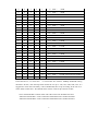
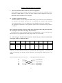
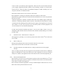
RC 905 EE1
Ethernet to E1 Interface Converter
User Manual
Contents
Chapter 1
Chapter 2
Chapter 3
Chapter 4
RC905-EE1(REV. B) Overview…………….…………….. 3
Operating Instruction………………………...…….………. 4
Connection………………..………………….………….…. 11
Troubleshooting………………………………………….. 12
2
Chapter 1 RC905-EE1 REV.B Overview
Modification of Rev. B (for the users of RC905-EE1 (REV.A), if you are new user, please
ignore it):
1.
2.
3.
4.
5.
Please be informed for the old customers that we’ve altered the definition of the 1st,
2nd and 3rd bit of SW2 switch on the bottom.
The duplex auto-negotiation capability is added at the Ethernet port to enable
connection with auto-negotiation port of switch.
The MDI/MDIX capability is added at the Ethernet port, which makes engineers not
confused by wire order.
The back pressure flow control in half duplex mode is added in the Ethernet port.
The limitation of broadcast storm is also added.
Special Specification:
RC905-EE1(REV.B) can be interoperated with old version REV.A, but please be noticed thin
the definitions of 1st and 3rd bit of SW2 have changed. If there are any questions, please consult
our technical staff.
RC905-EE1 cannot interoperate with RC901-EE1 and RC902-EE1.
Main Features:
z Provides one 10-BaseT Ethernet RJ45 port and one E1 (75 ohm BNC and 120 ohm RJ45)
port to perform transmission of Ethernet data in E1 Channel.
z Provides both fractional E1 and Transparent E1 modes. The E1 bandwidth can be set in the
fractional E1 mode as N*64Kbps (N=1-32).
z When working in the fractional E1 mode, it has the remote-site control function, can
control remote E1 loop-back, and can interrogate remote-site alarm information.
z Supports maximum Ethernet frame length up to 1593 bytes.
z Supports Full/Half-duplex auto-negotiation at the Ethernet port.
z Supports IEEE802.3x flow control in full duplex mode at the Ethernet port.
z Supports back pressure flow control in half duplex mode at the Ethernet port.
3
Chapter 2 Operating Instruction
I.
Introduction of Front Panel:
E1 Link Loss
Remote Loop-
Alarm
Back Indicator
Ethernet
Ethernet Link
TX/RX Action
RC905-EE1
LOS
LER
TX
BALANCE
RX
RLP
LNK
RAL
PWR
E1 LOF,AIS,CRC
Remote-site Alarm
Overall Alarm
Indicator
ACT
ETH
FDX
Full duplex mode
Power Indicator
z The definitions of indicators are as follows
E1 link indicators:
LOS (RED) Loss of receive signal alarm at E1 link;
When E1 link is working properly, it is off.
LER (RED) Fault alarm of receive signals at E1 link;
On fractional E1 pattern, this alarm indicates that there is loss of frame (LOF), AIS
(upstream E1 alarm) or CRC (CRC4 fault of fractional E1).
On E1 transparent (unframed) pattern, this alarm indicates AIS (upstream E1 alarm)
only.
When E1 link is working properly, it is off.
RLP(Yellow) It indicates the normal status of remote-site loop-back test.
On fractional E1 pattern, when setting this equipment on remote-site loop-back
mode by Dip-switch, if the RLP indicator is on, it indicates the test is successful,
and the link is in good condition.
When the device is working, it is off.
RAL (RED) It indicates remote-site E1 link alarm.
On E1 fractional pattern, when LOS or LER alarm occurs at the remote-site
equipment, the RAL at the local-site device is on.
When E1 is working properly, it is off.
Ethernet Link Indicators:
LNK(Green) When it is on, it indicates that network link is connected properly.
ACT(Green) When it is flashing, it indicates that data is transmitting and receiving.
4
FDX(Green) When the Ethernet link is working on full duplex mode, it is on; in the half
duplex mode, when the collision occurs, it is flashing.
Power Indicators:
PWR(Green) When power supply is working properly, it is on.
z Definitions of the Interfaces
E1 Interfaces
TX BNC connector 75ohm unbalanced Port E1 signal output.
RX BNC connector 75ohm unbalanced Port E1 signal input.
BALANCE RJ-45 connector 120ohm balanced port 1st and 2nd pins for Output 5th
and 6th pins for Input.
NOTE: RJ-45 balanced port and BNC unbalanced port cannot be used in the same time. Please
set up by Dip-switch before using. The factory default setting is 75 ohm BNC.
Ethernet Interface
ETH: Ethernet Unshielded Twisted Pair port please see the port definition and Link method
in the following chapter.
II.
Product Parameters
1. Technical Specifications of E1 Interface:
Bit Rate:
2048Kbps±50ppm
Line Code:
HDB3
Input Impedance:
75Ω(unbalanced BNC connector) , 120Ω(balanced RJ-45 connector)
Electrical Characteristics:
Compliant with ITU-T G.703 recommendation
Frame Structure:
Compliant with ITU-T G.704 recommendation (this equipment
supports time-slot allocation)
Jitter Tolerance:
Compliant with ITU-T G.823 recommendation
Functions:
Complete link alarm indication, Fault-Pass-Through (FPT), and intelligent
auto-restoration.
Note: When some other equipment such as PCM, DXC, etc., which need to modify the timeslot
0 of E1, are deployed along the transmission link, the loop-back control and remote-site alarm
interrogation capabilities will be disabled.
1. E1 Cable Type:
It is recommended to use SYV 75-2-2 cable with unbalanced BNC connectors. The
maximum transmission is about 200 meters.
For balanced RJ-45 port, 0.6mm (22AWG) Twisted Pair Cable is recommended.
5
1. Technical Specifications of Ethernet Interface
Uses 5-CAT cable for 10Base-T Unshielded Twisted Pair RJ-45 connector and it can transmit up
to 100 meters.
Supports IEEE 802.3 protocol and full/half duplex auto-negotiation
Supports fixed duplex mode, when auto-negotiation fails
Supports IEEE 802.3d Spanning Tree and IEEE 802.1q VLAN
Supports maximum Ethernet Data Frame length up to 1593 Bytes
Supports IEEE 802.3x flow control on full duplex mode
Supports back pressure flow control on half duplex mode
Supports auto MDI/MDIX capability
Built-in 1K MAC address list with address filtering function to increase E1 link efficiency
Built-in 64Mbit SDRAM memory to reduce data congestion
1. Working Temperature 0-45
Humidity 5%~90% non-condensing
5.
Power Supply: AC/DC optional
AC 220V/50Hz Input range 165V -- 265V
DC 48v Input range 36V -- -72V
Power Consumption 1W
6.
Dimension: 120 mm(W)×32 mm(H)×150 mm(D)
a. Switch Setup:
There are two 8-bit Dip-switches on the RC905-EE1 bottom panel. Please set up the
dip-switches before turning on the power of equipment.
1. SW2 (close to E1 port) Switch:
1 bit Duplex mode setup switch, in case duplex auto-negotiation of Ethernet port fails.
ON=Full duplex mode when auto-negotiation fails.
OFF=Half duplex mode when auto-negotiation fails (Default).
st
6
Bottom View
1 SW2
OFF
ON
E1 port
1 SW1
OFF
ON
8
8
Setup Switch, from top to button is 1-8 bits
Right is ON left is OFF.
It is needed to set up the Ethernet port working status of connected switches, hubs, or NICs
according to following table:
Port of Remote-site Equipment
10/100M Auto-negotiation
Switch Setup of Local
Equipment
Actual Working
Mode
Any
10M Full Duplex
Fixed 10M Half duplex
OFF (default)
10M Half Duplex
Fixed 10M Full Duplex
ON
10M Full Duplex
10M Duplex Auto-negotiation
Any
10M Full Duplex
Because the Ethernet port of the local equipment is set as on 10M full duplex auto-negotiation
mode, it cannot be connected with the port of fixed 100M rate.
2nd bit Please keep factory default status OFF, when the equipment is working properly.
3rd bit Fractional/transparent selection switch of E1 interface.
On = E 1 fractional mode. Transmission bit rate is N*64Kbps, N=1~31
OFF= E1 transparent mode, also called “un-fractional mode”, and the transmission bit rate
is 2048Kbps (Default).
At default status, the equipment is working on E1 transparent mode, and the dip-switch SW1 is
thoroughly disabled. Only when this bit is set up to fractional E1 mode, the 8 bits of dip-switch
SW1 is workable.
4th bit Remote loop-back control Switch of E1 interface, for engineers to test link condition.
ON= in test status Remote-site Loop back—E1 input signals of the remote-site equipment
is not processed internally, but directly output from the output port.
7
OFF= No loop back. When equipment is working in normal status, it should be OFF.
This bit of dip-switch can be set to test link status only when the equipment works in master
clock mode and on fractional E1 pattern.
Whether the remote-site loop-back is successful or not is judged by the RLP yellow indicator on
the front panel (On).
5th ~8th bits: For setting up impedance of E1 interface, please see the table below
5th bit
6th bit
7th bit
8th bit
75ohm BNC effective
ON
ON
ON
OFF
120ohm RJ-45 effective
OFF
OFF
OFF
ON
Dip-switch
Please set up interface impedance of E1 port strictly in conformity with the above table if not the
equipment will work improperly
SW2 Factory Default Configuration
Switch
1
2
3
4
ON
OFF
■
■
■
■
Definition
When
auto-negot
iation
fails, it’s
on Half
Duplex.
Disable
Fault-Pass
-Through
capability
Equipment is
on
transparent
E1 pattern.
Remote
Loopback
is disabled.
5
6
7
■
■
■
8
■
75 ohm BNC effective at E1
interface
SW1 dip-switches (only effective on the condition that the 3rd bit of SW2 is set up to
ON, i.e. in fractional E1 mode):
st
th
1 ~5 bit: For setting up the Ethernet bandwidth, i.e. N value of N*64kbps bit rate. Please see
the table below:
1.
1st Bit 2nd Bit 3rd Bit 4th Bit 5th Bit
Bandwidth (Unit: bit/s)
0
0
0
0
0
0 * 64 K =
0K
0
0
0
0
1
1 * 64 K =
64 K
0
0
0
1
0
2 * 64 K =
128 K
0
0
0
1
1
3 * 64 K =
192 K
0
0
1
0
0
4 * 64 K =
256 K
8
(Minimum bandwidth)
0
0
1
0
1
5 * 64 K =
320 K
0
0
1
1
0
6 * 64 K =
384 K
0
0
1
1
1
7 * 64 K =
448 K
0
1
0
0
0
8 * 64 K =
512 K
0
1
0
0
1
9 * 64 K =
576 K
0
1
0
1
0
10 * 64 K =
640 K
0
1
0
1
1
11 * 64 K =
704 K
0
1
1
0
0
12 * 64 K =
768 K
0
1
1
0
1
13 * 64 K =
832 K
0
1
1
1
0
14 * 64 K =
896 K
0
1
1
1
1
15 * 64 K =
960 K
1
0
0
0
0
16 * 64 K =
1024 K
1
0
0
0
1
17 * 64 K =
1088 K
1
0
0
1
0
18 * 64 K =
1152 K
1
0
0
1
1
19 * 64 K =
1216 K
1
0
1
0
0
20 * 64 K =
1280 K
1
0
1
0
1
21 * 64 K =
1344 K
1
0
1
1
0
22 * 64 K =
1408 K
1
0
1
1
1
23 * 64 K =
1472 K
1
1
0
0
0
24 * 64 K =
1536 K
1
1
0
0
1
25 * 64 K =
1600 K
1
1
0
1
0
26 * 64 K =
1664 K
1
1
0
1
1
27 * 64 K =
1728 K
1
1
1
0
0
28 * 64 K =
1792 K
1
1
1
0
1
29 * 64 K =
1856 K
1
1
1
1
0
30 * 64 K =
1920 K (Maximum bandwidth 1)
1
1
1
1
1
31 * 64 K =
1984 K (Maximum bandwidth 2)
In the table above, “0” means ON “1” means OFF. For instance, 384Kbps bandwidth setting
should be “00110”, then the Dip-switch should be set up as “ON, ON, OFF, OFF, ON”. It’s
suggested to write down the binary code of bandwidth, then set up according to the rule of “1
means OFF, 0 means ON”. The default status of these 5 bits of dip-switches is OFF.
Note: The bandwidth at central office and at the remote site should be the same.
“Maximum bandwidth 1” means maximum bandwidth for the condition PCM30
“Maximum bandwidth 2” means maximum bandwidth for the condition PCM31
9
6th bit PCM 31/30 selection dip-switch at fractional E1 pattern.
ON=PCM30 mode also called FAS+CAS mode.
OFF=PCM31 mode, also called FAS only mode (default mode).
This bit setting of dip-switch of two interoperated interface converters should be the same;
otherwise the equipment will not work properly.
7th bit CRC4 checkout selection dip-switch on E1 fractional mode.
ON= to disable CRC4 Checkout.
OFF= to enable CRC4 Checkout (default).
It can be set up as per the user’s requirement, but OFF is recommended to conduct
Checkout.
This bit setting of the dip-switch of two interoperated interface converters should be the same;
otherwise the equipment will work not properly.
8th bit ON/OFF clock mode selection dip-switch.
ON = Receive Timing following E1 link, also called Slave Clock.
OFF = Local timing, also called Master Clock (default).
This bit setting is effective only at fractional E1 pattern.
If working at fractional E1 pattern, one device should be set up to master clock mode, and
the other should be slave clock mode, otherwise they will not work properly. If DXC, PCM
/MUX equipment is used in the E1 link, there should be only one master clock in the whole E1
link, and the rest equipment just follow E1 link receiving clock.
SW1 Factory Default Setting
Switch
1
2
3
4
5
6
7
8
■
■
■
■
■
■
■
■
PCM31
CRC3
Enable
Master
Clock
ON
OFF
Meaning
Full Timeslot N=31
Please note: Before applying power supply, in order to prevent excessive power level difference
between equipment along the E1 link, and protect equipment interfaces, it is recommended that
connect E1 link first before turning on the power supply. Try the best not to hot-swap the E1
interfaces.
a. Occupation of forwarding data on fractional E1 mode:
z Timeslot occupation on the PCM31 mode
On the PCM31 mode, N≤31, the timeslot 0 is occupied by the system. N is counted from
1st timeslot.
10
TS[0]
TS[1]
……
TS[N]
……
TS[31]
V.35 BANDWIDTH
z
Timeslot occupation on the PCM30 mode
On the PCM31 mode, N≤30, the 0 and 16th timeslots are occupied by the system. N is
counted from the 1st timeslot. If N is bigger than 16, it will skip over 16th timeslot.
TS[0] TS[1]
……
TS[16]
……
V.35 BANDWIDTH
11
TS[N+1]
……
TS[31]
Chapter 3 Equipment Connection
I.
Make sure E1 link cable matches the connected equipment.
If the equipment connected with RC interface converters in E1 link are comprised of such
equipment as PDH, SDH, etc., please refer to the manuals of these equipment for the type,
definition and line impedance of E1 interfaces.
II. Ordinary Application Solution
When the interface converter adopts all default settings, it provides one 75 ohm unbalanced
E1 interface, one Ethernet port that can be connected with switches with 10/100M
auto-negotiation ports or low cost HUB to provide 2048Kbps transmission bandwidth.
For adjustment of parameters of the equipment, please refer to instructions of dip-switches
in chapter 2.
III. Connect the interface converter with CAT 5 twisted pair cable, and please note that
the twisted pair cable shall be no longer than 100 meters.
The Ethernet port of this equipment supports auto MID/MIDX. It can be connected with
Ethernet ports of any equipment with either straight cable or crossover cable.
IV. When using the 120ohm balanced interface, the E1 link pins of the BALANCE-RJ45
twisted pair cable are defined as follows
PIN No.
1
2
3
4
5
6
7
8
Definition
TD+
TD-
NC
NC
RD+
RD-
NC
NC
Meaning
Signal
Output+
Signal
Output-
Suspend
Suspend
Signal
Input+
Signal
Input-
Suspend
Suspend
When the 120 ohm balanced connector is connected with other equipment, it’s necessary to
make clear definition for the pins of other equipment. The connection method of pins is as
follows
BALANCE-RJ45 of RC series converter
E1 link equipment balanced connector
TD
TD
RD
RD
Signal Output
Signal Output
Signal Input
Signal Input
12
Notice: When connecting the twisted pair cables, TD and TD should be twisted as a pair, and
RD and RD too.
V. RC905 Ethernet to E1 interface converters should be utilized in pairs in point to
point mode. It cannot be interconnected with third party Ethernet to E1 interface
converters.
VI. Installation of DC Power Supply:
DC power supply provides three connecter ends: –48V, ground and 0V. These three connecter
ends are connected respectively with –48V power cable, ground protection (PGND) and 0V
power cable.
Note: PGND Connection is necessary for safety operation of equipment.
-48V
13
Ground
0V
Chapter 4 Troubleshooting
If there is any problem during installation and application please try to solve it according to the
following suggestions. If it is not solved yet, please contact technical staff for support.
I.
Power indicator PWR is OFF
There is fault with power supply system.
II.
Ethernet link indicator LNK is OFF
Check whether the network cable is disconnected.
Check whether the link type is matching the straight cables shall be used to connect switches
and HUB’s; the cross-over cables shall be used to connect routers and NIC’s.
Check whether the transmission bit rate is matching; the bit rate of the Ethernet ports of the
equipment connected with interface converts shall be auto-negotiation or fixed 10M.
III.
Link loss alarm indicator LOS of E1 link is ON
LOS alarm indicates E1 interface cannot receive signals.
Check whether E1 input signal link is connected well and whether wire order of 120ohm
twisted pair cable connector is correct.
Check whether there is any power off with the equipment connected with interface
converter.
Please check whether E1 receive link is disconnected with bit error tester.
IV.
LER indicator is on
It indicates that at least one kind of alarm occurs among E1 Loss of frame alignment (LOF),
upstream link alarm (AIS) and checkout fault (CRC).
When equipment is working at transparent mode, LER alarm means AIS alarm only.
Please check whether there is any power off with the E1 uplink equipment.
Please check whether the interface impedance setting is correct. In the case of using
120ohm twisted pair cable connector, check whether the wire order is correct and whether
the connection is loose.
Please check whether E1 transmit link is disconnected with bit error tester, and whether the
bit error rate is beyond limit.
LOF alarm causes LER indicator flashing or blinking, it indicates there is loss of frame
alignment of E1 signal.
When the equipment works at transparent pattern, there shall be no LOF alarm.
Please check whether the interface impedance setting is correct.
Please check whether bit error rate is beyond limit with bit error tester.
14
If the E1 link is provided by other equipment, within the first several minutes after the
power supply is applied, LER alarm indicator may be flashing, and this is in normal status.
Please wait for a while, the alarm will gradually disappear. If LER is flashing for a very
long time, the link is in abnormal status.
CRC alarm indicates there is severe bit error with E1 link.
If the equipment is working in transparent mode, there shall be no CRC alarm.
CRC alarm may appear with LOS or AIS. Please check whether bit error rate is beyond limit
with bit error tester.
When the equipment is working, sometimes CRC alarm may suddenly appear, LER alarm
indicator is frequently flashing, and the network is disconnected. The problem is usually
caused by the link initializing process that the power supply of the equipment is cut off and
then turned on. In this case, stop the service with heavy traffic, and the equipment will
recover the link in 10~30 seconds automatically.
If CRC Check selection ON/OFF dip-switch——the 7th bit of SW1 switch is set up as
ON(disable CRC checkout function) then this alarm indicator (LER) flashing is not caused
by CRC check.
V.
Link disconnects RLP indicator is steady ON.
The equipment is probably set in remote loop-back mode. Please check 4th bit of SW2 and
set it to OFF.
VI.
RAL is steady ON
Remote alarm indicates there is fault occurred at remote E1 receive link.
Please check the link status of local TX to remote-site RX.
VII.
No alarm indication and LNK indicator is steady ON but link can not be pinged
through.
This is normally caused by that some equipment in the network has been fixed as 100M half
duplex or full duplex at E1 port. The electric port of this equipment can only be connected
with ports of 10M or self-negotiation. Please check the bit rate of network equipment port.
VIII. Severe network packet loss.
If the interface converter is set up at fractional E1 pattern (refer to the definition of 3rd bit of
SW2 on the button panel), then it is needed to set Master Clock mode on one side and Slave
Clock mode on another side equipment.
If the interface of Ethernet equipment is set up as 10M full duplex mode, then the 1st bit of
SW2 on the bottom panel should be set as ON.
15