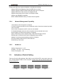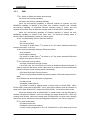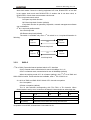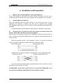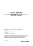
1
RC952-FEE1 (A)
Fast Ethernet to E1 Interface Converter
(REV.A)
User Manual
Raisecom Technology Co., Ltd
08/2005
Raisecom Technology Co., Ltd
Contents
1.
Cautions..................................................................................................................... 2
2.
Overview .................................................................................................................... 3
2.1.
2.2.
3.
Introduction ......................................................................................................... 3
Features.............................................................................................................. 3
How to use ................................................................................................................. 4
3.1. Introduction of Front Panel.................................................................................. 4
3.1.1.
The indicator indicates................................................................................. 4
3.1.2.
Interface Definition....................................................................................... 5
3.2. Basic Specification.............................................................................................. 5
3.2.1.
E1 Interface Technical Specification ............................................................ 5
3.2.2.
E1 Cable Type ............................................................................................. 5
3.2.3.
Ethernet Interface Technical Specification ................................................... 5
3.2.4.
Network Management Capability ................................................................. 6
3.2.5.
Ambience..................................................................................................... 6
3.3. Indication of Switch Setting................................................................................. 6
3.3.1.
SW1............................................................................................................. 7
3.3.2.
SW2~5......................................................................................................... 8
3.3.3.
SW6............................................................................................................. 9
4.
Installation and Preparation ..................................................................................... 10
5.
Troubleshooting ........................................................................................................11
1
Raisecom Technology Co., Ltd
1. Cautions
Please read the following notices carefully before installing
and using the device, Raisecom does not respond to any loss
that caused by violating safety notices.
RC952-FEE1 is integrated equipment. Move carefully and do
not disassemble or mend it without the guidance of Raisecom
technical engineer with the anti-static procedures.
The equipment must be grounded. Do not disassemble the
equipment by yourself. It may cause unrecoverable damage.
Raisecom will not be responsible for the damage by this.
2
Raisecom Technology Co., Ltd
2. Overview
2.1.
Introduction
RC952-FEE1 is converting equipment of one 10/100M auto-sensing Ethernet port to one
E1. This equipment may be used in point-to-point topology, it can be network managed
with RC series equipment. RC952-FEE1 interface converter is installed in 16-slot or 4-slot
chassis of Raisecom. RC952-FEE1 also can be installed in 1-slot chassis used as remote
standalone equipment; it works with local equipment to realize remote network
management.
2.2.
Features
RC952-FEE1 provides one 10/100M auto-sensing Fast Ethernet RJ45 interface and one
E1 (75 ohm) interface, to realize transmission of Ethernet signals in E1 channel.
z E1 port supports framed and unframed mode
z Time-slot can be appointed random, when the E1 mode is framed. The function of E1
CRC automatic detection is available.
z Support optional function of E1 link BERT.
z Support local and remote loop-back of E1 port.
z E1 interface supports two clock modes: master clock and slave clock.
z Ethernet port supports 10/100M auto-sensing function.
z Support IEEE802.3x flow control in full duplex mode of Ethernet port.
z Support back pressure flow control in half duplex mode of Ethernet port.
z Ethernet port supports maximum frame size of 1916 bytes.
z Local and remote network management function, alarm and Ethernet port message
information inquiry of local and remote equipment.
z Support network management under E1 unframed mode. Support network
management of passing DXC/PCM equipment under E1 framed mode.
3
Raisecom Technology Co., Ltd
3. How to use
3.1.
Introduction of Front Panel
LER
3.1.1.
RLP
TX
RX
RAL
LNK/ACT
100M
FDX
PWR
RC952-FEE1
LOS
The indicator indicates
E1 link indicators:
LOS(Red):Receiving signal loss alarm of local E1 link, LOS-On, without LOS-Off.
LER (Double Color): The rest local alarm. AIS—Flashing with red color, LOF—On with
yellow color, CRC—Flashing with yellow color, no alarm—Off.
RLP (Double Color): Test indicator of remote loop-back and BERT.
Test of remote loop-back: test is failure-Flashing with yellow color,
test is successful-On with yellow color
Test of BERT: there are error bits-Flashing with green color, there
are no error bits-On with green color
Normal working condition-Off.
The information of indicator is BERT, when the test of BERT and
remote loop-back is available at the same time.
RAL (Double Color): E1 link alarm of remote equipment.
LOS-On with red color, AIS—Flashing with red color,
LOF—On with yellow color, CRC—Flashing with yellow color,
no alarm-Off.
The definition of above alarm is following:
LOS:Loss of receiving signals of E1
AIS: Receiving signals of E1 is 1, there is fault in upstream equipment general.
LOF: When working mode of E1 is framed, it means the frame is asynchronous
When working mode of E1 is unframed, it means there is abnormal frame.
CRC: When working mode of E1 is framed, the alarm is E1 CRC alarm.
When working mode of E1 is unframed, the alarm is HDLC CRC alarm.
Ethernet indicators:
LNK/ACT (Green):When it is on, it indicates that network link is connected properly.
When it is flashing, it indicates that there is data transmitting and receiving
4
Raisecom Technology Co., Ltd
action in Ethernet.
100M (Yellow): 100M-On, 10M-Off.
FDX(Green):On, Ethernet is working on full duplex mode
Flashing, there is collision on half duplex mode.
Power Indicator:
PWR(Green):Steady ON, power supply is working in normal condition.
3.1.2.
Interface Definition
E1 BNC Interface:
TX:BNC connector,75ohm unbalanced Port,E1 signal output.
RX:BNC connector,75ohm unbalanced Port,E1 signal input.
Ethernet Interface:
ETH: RJ45 connector, complies with the interface definition of standard Ethernet
3.2.
Basic Specification
3.2.1.
E1 Interface Technical Specification
Bit Rate:
2048Kbps±50ppm
Line Code:
HDB3
Input Impedance:
75Ω(unbalanced BNC connector)
Electrical Characteristic: Compliant with ITU-T G.703 recommendation
Fractional Structure:
Compliant with ITU-T G.704 recommendation
(this equipment supports timeslot allocation)
Jitter Tolerance:
Compliant with ITU-T G.823 recommendation
Functionalities:
Complete link alarm indicator, Fault-Pass-Through (FPT)
and intelligent auto-restoration functions.
3.2.2. E1 Cable Type
It’s suggested that SYV 75-2-2 coaxial cable is used for unbalanced BNC connector.
Its maximum transmission distance is more than 200 meters.
3.2.3.
Ethernet Interface Technical Specification
Use 5-CAT cable for Unshielded Twisted Pair RJ-45 connector and it can transmit up to
100 meters.
5
Raisecom Technology Co., Ltd
Comply with IEEE 802.3 protocol standard, 10/100M auto-sensing.
Support IEEE 802.3d Spanning Tree and IEEE 802.1q VLAN.
Support maximum Ethernet Data Fractional length up to 1916 Bytes.
Support IEEE 802.3x flow control on full duplex mode.
Support back pressure flow control on half duplex mode.
Support auto MDI/MDIX capability.
Built-in 32Mbit SDRAM memory to reduce data congestion.
3.2.4.
Network Management Capability
4-level alarm of E1 link reports to computer.
Local and remote loop-back can be configured, result of local and remote loop-back
can be checked.
Clock mode of equipment and E1 mode can be checked.
E1 framed/unframed mode, time-slot occupation and clock mode can be set.
Running status of Ethernet port reports to computer.
Query of Ethernet port rate, duplex setting, Fault-Pass-Through function.
Ethernet port is closed and sub-card is stopped through software.
Statistic of receiving and transmitting packets of Ethernet.
Error bits statistic under the test of error bits test.
Historical log of all events.
3.2.5.
Ambience
Working Temperature:0-45℃
Humidity:5%~90% non-condensing
Power Consumption:3W
3.3.
Indication of Switch Setting
There are five 8-bit Dip-switches SW1~SW5 on the RC952-FEE1 rear panel, there are
one 4-bit Dip-switches SW6 on the front panel. Please setup the Dip-switches before the
device powered on.
6
Raisecom Technology Co., Ltd
3.3.1.
SW1
1st bit:Switch of Ethernet interface auto-sensing.
On=Close auto-sensing capability.
Off=Open auto-sensing capability (default).
When the auto-sensing capability of Ethernet interface is opened, the auto
MDI/MDIX capability is opened at the same time. Ethernet interface has 10/100M
auto-sensing capability. If connected Ethernet interface mode of switch, hub and
network-card is fixed, then the Ethernet working mode of RC952-FEE1 is half-duplex.
When the auto-sensing capability of Ethernet interface is closed, the auto
MDI/MDIX capability is closed at the same time. The Ethernet working mode of
RC952-FEE1 is determined by 2nd bit and 3rd bit switch.
2nd bit: 10/100M setting switch of Ethernet interface
On=10M
Off=1001M (default)
The switch is invalid when 1st bit switch is off. The switch determines Ethernet
interface rate when 1st bit is on.
3rd bit: Duplex mode switch setting of Ethernet interface
On=half-duplex
Off=full-duplex (default)
The switch is invalid when 1st bit switch is off. The switch determines Ethernet
duplex mode when 1st bit is on.
4th bit: Fault-Pass-Through switch
On=Open Fault-Pass-Through function.
Local LOS, LOF, AIS, CRC alarm of E1 link can disable the Ethernet interface, in
order to report the link fault to switch. When there is no alarm of E1 link, the Ethernet
interface resumes normal working status automatically.
Off=Close Fault-Pass-Through function.
There is no association between the working status of Ethernet interface and E1
alarm
5th bit: Master and slave mode switch of equipment
On=Slave mode
Off=Master mode (default)
The switch is used for setting master or slave mode of RC952-FEE1. When
RC952-FEE1 works with RC952-FEE1, one is must be set master mode and another is
slave mode. When RC952-FEE1 works with RC951-8FEE1, it must be set slave mode.
When the working mode of RC952-FEE1 is master mode, it can be managed by
network management software. And it can manage the remote RC952-FEE1, which the
working mode is slave. When the working mode of RC952-FEE1 is slave mode. Working
status only can be checked by network management software, it can not be configured.
6th bit: Clock mode switch
On=Slave clock mode
Off=Master clock mode (default)
If there is timing equipment in E1 link, RC952-FEE1 of both sites must be set
7
Raisecom Technology Co., Ltd
slave clock mode. If there is no timing equipment in E1 link, RC952-FEE1 of one site
is set master clock mode and RC952-FEE1 of another site is set slave clock, or
RC952-FEE1 of both sites are set master clock mode.
7th bit: Loop-back control switch
On=Open loop-back function
Off=Close loop-back function (default)
If loop-back function is opened by Dip-switch, network management software
can not disable it.
8th bit: Loop-back position switch
On=Local loop-back
Off=Remote loop-back (default)
The switch is available only when 7th bit switch is on. Loop-back illustration is
following:
Local
E1
equipment
Remote
equipment
Remote loop-back
Local
E1
equipment
Remote
equipment
Local loop-back
3.3.2.
SW2~5
1st bit of SW2: Framed/unframed optional switch of E1 interface
On=E1 framed mode. transmission bit rate is N*64Kbps, N=1~31
Off=E1 unframed mode, transmission bit rate is 2048Kbps (default)
When the working mode of E1 is unframed (default), the 2nd~8th bit of SW2 and
SW3~SW5 is invalid. These switches are available, when 1st bit of SW2 is on.
2nd~8th bit of SW2 and SW3~SW5: Switch of E1 time-slot occupation
On= Occupation
Off=Not occupation (default)
The 31 bits switches corresponding with TS1~TS31 of E1 time-slot. When
framed mode is set by user, it needs to set these 31 bits switches to select time-slot.
SW2
SW3
SW4
SW5
1~8
1~8
1~8
1
2~8
TS0
TS1~TS31
ON
Framed
Ethernet service occupies the time-slot
OFF
Unframed
Ethernet service does not occupy the time-slot
Note: When E1 is framed mode, it needs to ensure the switches of time-slot
occupation is not all Off, at least there is one switch is On.
8
Raisecom Technology Co., Ltd
3.3.3.
SW6
1st and 2nd bit: Mode switch
1st bit
2nd bit
Mode
OFF
Random
Mode 1
ON
ON
Mode 2
ON
OFF
Mode 3
When the equipment is set mode 2 or mode 3,
equipment must be unframed mode.
E1 is unframed mode. So the another site
3rd bit: Buffer size optional switch
ON=Small buffer
OFF=Big buffer (default)
When the equipment uses big buffer, it is suitable for to transmit data service, when
the equipment uses small buffer, it is suitable for to transmit image service.
4th bit: Error bits test switch
On=Open error bits test function
Off=Close error bits test function (default)
The function is convenient for users to test network. At present, error bits
test supports statistic function of ES and SES, which is stated in G.821/826 protocol.
But statistic period is fixed 5 minutes (nonstandard). During the 5 minutes test period,
status of error bits can be checked through network management.
The equipment transmits Pseudo-Random Test Sequence at all times during
the test of error bits, and service and network management control will be stopped.
So when using the function, remote equipment should be set local loop-back status or
local equipment should be set remote loop-back status.
When applying the power supply, please note: in order to prevent between E1
line equipment potential difference oversized, for the equipment connection security.
It is suggested user first connect E1 line then turn on power supply. The E1 interface
should avoid hotly inserting and pulling out.
9
Raisecom Technology Co., Ltd
4. Installation and Preparation
I.
Make sure E1 Link Cable Matches Connected Equipment
If PDH, SDH equipment are linked to RC series interface converter of E1 link,then it
should be referred to manuals for the type, definition and line impedance of E1 interface.
II.
Ordinary Application Solution
When this equipment adopts all default settings, it can provide user with a 75 ohm
unbalanced E1 interface, a Ethernet port that can be connected with 10/100M
auto-negotiation ports switch or low cost HUB to provide 2048Kbps actual transmission
bandwidth.
To adjust parameters of this equipment, please refer to introductions of Dip-switch.
III.
Connecting CAT 5 Twisted Pair Cable with Interface Converter, please note
that the Twisted Pair Cable does not exceed 100 Meters.
Ethernet port of this equipment supports auto MID/MIDX, when auto-sensing function is
open. It can be connected with Ethernet ports of any equipment with either direct cable or
crossover cable.
When auto-sensing function of the equipment is close, if it connects to Ethernet
Switch, Hub and etc equipment, it should adopt direct twisted pair cable.
RC952-FEE1 RJ-45
Ethernet Switch RJ-45
Pin 1
Pin 1
Pin 2
Pin 2
Pin 3
Pin 3
Pin 6
Pin 6
If RC952-FEE1 connects to computer, it should adopt crossover twisted pair cable.
RC952-FEE1 RJ-45
Computer network-card RJ-45
Pin 1
Pin 1
Pin 2
Pin 2
Pin 3
Pin 3
Pin 6
Pin 6
In the two connection method, please note that two lines of Pin 1 and Pin 2 is a pair
and two line of Pin 3 and Pin 6 is a pair.
IV. RC952-FEE1 can be used as point to point, it can work with RC952-FXE1. It can
also work with standalone RC951 Ethernet to E1 interface converter.
10
Raisecom Technology Co., Ltd
5. Troubleshooting
If you meet troubles in installation and application,please try to solve the problems
according to the following suggestions. If they cannot be solved, please contact technical
staff to support.
I.
II.
Power indicator(PWR)is OFF
There is fault in power supply system.
Ethernet link indicator(LNK)is OFF
Please check whether the network cable is cut off.
Please check whether bit rate is matching
Please check whether Fault-Pass-Through function is open and there is fault in E1
link.
III.
Interruption alarm indicator(LOS)in E1 link is ON
LOS alarm indicates E1 interface cannot receive signal.
Please check whether E1 input signal link is connected well.
Please check whether there is power off in the equipment connected with E1
interface of interface converter.
IV.
LER indicator is on
Please check whether there is power off in the E1 uplink.
Please test whether E1 transmitting link disconnects, and if bit error rate is beyond
limit.
CRC alarm reminds you that there is Serious Error Bits in E1 link.
V.
Link disconnects,RLP indicator is constant ON.
The equipment is probably set on remote loop back mode. Please check 7th bit of
SW1,and set it to OFF.
VI.
RAL is steady ON
Remote alarm indicates there is fault occurred at remote receiving E1 link.
Please check the link status from local TX to remote RX.
VII.
No alarm indication and LNK indicator is constant ON,but link can not be ping
through.
Please check time-slot setting of both sites equipment.
11
Raisecom Technology Co., Ltd
@2005 Raisecom Technology Co., Ltd.
All trademarks are the property of their respective owners.
Technical information may be subject to change without prior notification.
12