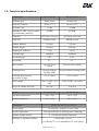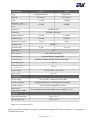
1
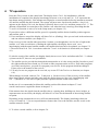
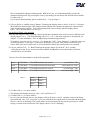
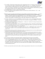
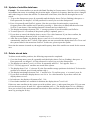
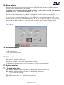
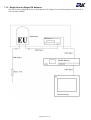
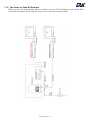
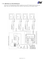
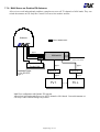
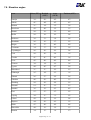
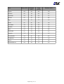
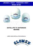
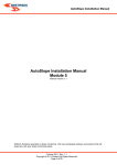
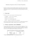
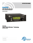
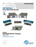
Manual River Line TV43 & TV58 Basic Line TV44 & TV59 Premium Line TV61 & TV90 English V2.08 / 2010 Manual River Line TV43 & TV58 Basic Line TV44 & TV59 Premium Line TV61 & TV90 The technical data, information and illustrations contained in this publication were to the best of our knowledge correct at the time of printing. No liability can be accepted for any inaccuracies or comissions in the publication, although every care has been taken to make it as complete and accurate as possible. English Page 2 / 34 Contents 1. The digital satellite tracking system...............................................................................................4 1.1. EPAK®-TV system overview...........................................................................................................................................................4 1.2. Safety recommendations................................................................................................................................................................5 2. Installation.........................................................................................................................................6 2.1. Standard delivery............................................................................................................................................................................6 2.2. Installation overview........................................................................................................................................................................6 2.3. Selecting location............................................................................................................................................................................6 2.4. Mounting surface.............................................................................................................................................................................7 2.5. Planning the cable paths.................................................................................................................................................................7 2.6. Power supply...................................................................................................................................................................................7 2.7. Drillings...........................................................................................................................................................................................8 2.8. Mounting the antenna unit.............................................................................................................................................................11 2.9. System cable connections.............................................................................................................................................................11 3. Control elements.............................................................................................................................12 3.1. Control unit....................................................................................................................................................................................12 3.2. Preparing the receiver...................................................................................................................................................................12 3.3. Power on / off / Standby................................................................................................................................................................12 3.4. Password access to Setup menu..................................................................................................................................................13 3.5. Adjusting the Setup parameters....................................................................................................................................................13 4. TV operation....................................................................................................................................14 4.1. Stopping the Tracking function in harbours...................................................................................................................................15 5. Satellites...........................................................................................................................................15 5.1. Adding new satellites.....................................................................................................................................................................15 5.2. Update of satellite data base.........................................................................................................................................................18 5.3. Delete stored data.........................................................................................................................................................................18 5.4. Selection of stored satellites.........................................................................................................................................................19 5.4.1. Automatic selection of satellites............................................................................................................................................19 5.4.2. Manual selection of satellites................................................................................................................................................19 6. Miscellaneous..................................................................................................................................20 6.1. Adjustments of LNB- type..............................................................................................................................................................20 6.2. Special functions via the Standby mode.......................................................................................................................................20 6.3. Fastscan function (US only)..........................................................................................................................................................21 7. APPENDICES...................................................................................................................................21 7.1. Maintenance..................................................................................................................................................................................21 7.2. Overview of menu structure..........................................................................................................................................................22 7.3. Troubleshooting.............................................................................................................................................................................23 7.4. Skew settings................................................................................................................................................................................25 7.5. Replaceable parts.........................................................................................................................................................................25 7.6. Optional parts................................................................................................................................................................................25 7.7. System overview...........................................................................................................................................................................25 7.7.1. General cable data...............................................................................................................................................................25 7.7.2. Single User on Single EU Antenna.......................................................................................................................................26 7.7.3. Multi Users on Single EU Antenna.......................................................................................................................................27 7.7.4. Two Users on Twin EU Antenna...........................................................................................................................................28 7.7.5. Multi Users on Twin EU Antenna..........................................................................................................................................29 7.7.6. Multi Users on Quattro EU Antenna.....................................................................................................................................30 7.8. Elevation angles............................................................................................................................................................................31 7.9. Technical specifications.................................................................................................................................................................33 English Page 3 / 34 1. The digital satellite tracking system The advanced technologies of the satellite tracking system EPAK-TV makes an excellent television reception possible. An 360° high-speed tracking guarantees a non-stop reception of your favourite channels even during your trip in open seas. Once the connection to a satellite is established, the tracking system will stay connected to that satellite even in the roughest sea conditions. The EPAK-TV system is suitable for vessels of any size including smaller boats of less than 36ft (11m). According to different tracking conditions of the respective region a choice between a reflector antenna dish of 18'' (45cm), 23.6'' (60cm) and 35” (90cm) in diameter is neccessary. The antenna is capable of tracking horizontally, vertically and in case of the Premium Line antennas also in polarization angle (skew) due to its direct servo drive. We developed the patent-registered high-speed tracking sensors that provide together with other high-tech components a topmost and dynamic tracking accuracy of a satellite. The TV-system is protected by a UV-stabilized and maritime climate proof radome. To provide an unlimited reception of available channels – just like at home, we attach great importance to high tracking stability and quality as well as easy handling and maintenance. Note! The reception of channels in different regions depends on the footprints of the satellites. Also, the TV reception can be affected by rain, snow, dense clouds and extreme movement thus there is no warranty for the reception of certain channels. Note!! Don't use alcohol, dilution or similar products for cleaning the radome! 1.1. EPAK®-TV system overview Models Single Twin Quattro Bands EU TV 43 / TV 44 X X - 4 TV 58 / TV 59 X X X 4 TV 61 / TV 90 - - X 4 If you wish to use the respective antenna with one or more receivers, please check chapter 7.6.2 of the manual. English Page 4 / 34 1.2. Safety recommendations 1. Please consider the maximum allowable power voltage for the antenna unit. The DC voltage must be between 12 and 36 volts and the overload protection should be rated at min. 5 amp. and max. 7.5 amp.. 2. The mounting distance from the antenna unit to other radiation sources, e.g. radar equipment or other transmitting antennas, should be at min. 2.5 m (8 ft). 3. If the satellite antenna is not installed above the radar antenna, simultaneous operation of both systems may damage the satellite antenna. 4. Do not use the control unit outdoors! 5. During a thunderstorm, we recommend to disconnect all connection cables. 6. If the negative side of the antenna unit’s supply voltage has no connection to the ship’s ground (earth), then the antenna unit’s ground point should be connected directly to the ship’s ground (earth). 7. After the installation is completed all other electronic systems, i.e. GPS, Radar, VHF, FM, AM etc., should be tested for full functionality while the antenna is turned on. 8. Do not test or turn on the antenna before the radome is fitted correctly. The electronics can be damaged by the reflected sun. 9. Do not touch the rotary joint. 10. Do not open the sealed electronic box, as this will void the warranty. English Page 5 / 34 2. Installation 2.1. Standard delivery The satellite tracking system EPAK-TV comes complete with the antenna and the following system components: • Antenna unit (with serial number) • Control unit • Four mounting screws M 8 • Manual Please check the completeness of all components. Make sure that no transport damages exist before you start the installation. 2.2. Installation overview The installation work has to be done in the following order: • Select location • Check the mounting surface for stability • Check cable path • Position of power distributor • Drill holes and lay the cable • Install antenna unit (see also addendum for instructions of how to undo the fixed transportation position before power-up) • Make all installation openings watertight • Connect cables For the installation at least the following tools are needed: • Electric drill • One 4mm and one 8.5-9 mm drill bits • Hexagon socket screw key size 6 and 4 • 13mm screw wrench Plan the entire installation first! To avoid mistakes or damages to the boat or satellite tracking system, please read the installation instructions carefully before starting the installation. 2.3. Selecting location The best location for the TV-antenna is a raised position on your ship. Thus, the needed unobstructed view from the antenna to the satellite with the respective elevation angle can be established. In order not to affect the picture quality or not to damage the antenna, please observe the minimum distance of 8-12ft. (2-3 meters) to the radar equipment and other transmitting antennas! That includes mobile communication units! If there is a radar antenna, the ideal location to mount the antenna will be right above the radar antenna. Please also note that a strong mounting surface is needed and please avoid direct waves and bilge water on the radome. For further details see chapters 2.4 – 2.9. English Page 6 / 34 The following illustration shows the importance of a proper location for the antenna unit. 2.4. Mounting surface A horizontal, solid and steady, and even surface has to be ensured. The weight of the antenna unit can be 26.5lbs (12kg) up to 123.6lbs (56kg) (depending on the model) and must not be confronted with punctual material stressing. The surface has to be strong enough to carry the antenna unit, even during the most challenging maritime conditions. 2.5. Planning the cable paths Before starting the installation, please check which walls are suitable and if existing openings can be used for the cables. All openings have to be sealed! The control unit should be placed as close as possible to the receiver. The cable length should not extend 3 m and the cable must be type 1 (see chapter 7.6.1 for data concerning appropriate cable types). 2.6. Power supply The antenna unit can be connected directly without a converter to any ship's power supply net of 12/24/32 volts DC. The circuit fuse should be rated for min. 5 amperes and max. 7.5 amperes! (see chapter 7.8 “Technical Specifications”). The power distributor must be idle while working on the ship's supply net or you short circuit the system. If the negative side of the supply voltage of the antenna unit has no connection to the boat ground, make sure a potential compensation between boat ground and the ground point of the antenna unit is made. English Page 7 / 34 2.7. Drillings For an ideal mounting of the antenna we prepared all possible drilling pictures with a diameter of 2 mm in the bottom of the radome. Please refer to the included template for the drilling measurements (see bottom from below!). The drilling holes have to have a size of ∅ 8.5 – 9 mm for the included M8 screws. We recommend to start with drilling a smaller hole, using a ∅ 3.5 – 4 mm bit to avoid any damage to the mounting surface. To mount the antenna, only use the included M8 mounting screws! !! If the antenna unit is not mounted on a device carrier or separate mounting plate, close all drilled holes with waterproof sealing material to avoid any water penetrating! Possible dimensions: River Line & Basic Line: 228.6 mm x 228.6 mm and 134.2 mm x 77.5 mm For a good and steady mounting of the antenna we recommend the drilling picture 228.6 mm x 228.6 mm. For the drilling picture 134.2 mm x 77.5 mm you will find tapped holes at the bottom plate of the antenna, so no nuts would be necessary. Bow English Page 8 / 34 Premium Line: 228.6 mm x 228.6 mm TV90 Bow English Page 9 / 34 Premium Line: 228.6 mm x 228.6 mm TV61 English Page 10 / 34 2.8. Mounting the antenna unit The antenna unit has to be mounted on a solid and steady surface. Take care that the cable lengths are sufficient - the antenna unit must have an unobstructed view to the satellite and that there are no interfering fields (especially mobile communication antennas) nearby. Place the antenna unit on the predrilled holes and fasten it with the included screws and washers. The screws have to be screwed in from below through the mounting surface into the radome. !! Close all drilled holes with waterproof sealing material to avoid any water penetrating! 2.9. System cable connections !! Break the contact of the circuit on which you are working to avoid a short circuit of the system. • The antenna cable must be connected to the control unit and the antenna unit, (cable type 1). • The power supply cable to the power distributor and the antenna unit. • The receiver cable to the control unit and the receiver, (cable type 1). !! See system overview and illustration details, chapter 7.6.1 and at the end of the manual. Lead the cable through the drilled holes and seal it with waterproof sealing material. Furthermore, drip loops should precede the entry point from the exterior to avoid any water penetrating. See illustration below: Find a suitable location for all units within cable lengths, meaning the control unit should be placed nearby the receiver. Take care that the display of the control unit can be easily read and the buttons are accessible. Also, allow room for the cables behind the control unit! The antenna unit is separated from the power supply net by the control unit. Therefore, the antenna unit only has electric power when the control unit is turned on! English Page 11 / 34 3. Control elements 3.1. Control unit The EPAK-TV system is controlled by the control unit. See below a short overview of the key functions: Power key: Shortly pressed will turn on power or will enter Standby mode. Browse key: Shortly pressed will browse through all available menus and setups or will cancel a current process. Select key: Shortly pressed will select/confirm what is written in the display. Note! From the Standby mode: Press and hold the Select key while using the Browse key to scroll through available data: serial no., counter operation time, and software versions ( see chapter 6.3.). 3.2. Preparing the receiver EPAK-TV does not need a special receiver. The satellite tracking system can be connected to any commercial receiver for digital and analogue reception. Only the LNB-type in the setup menu of the receiver has to be set on “Universal” (LOF 9,75/10,6 Ghz). If you want several satellite positions, the DiSEqC ™ function for an automatic satellite switch has to be activated (not valid for Quattro antennas) To program your receiver, please refer to the respective owner's manual! !! For every satellite at least one program must be preprogrammed in the receiver to control the satellite position of the antenna unit by means of the TV picture quality. If not, pre-program the receiver by using an already installed satellite system! !! In case the receiver supports the function, adjust the receiver so that the power supply of the LNB is turned off during the Standby-mode. This means that the control unit and the antenna unit are without power supply. This function enables the turning on and off of the antenna unit via remote control of the receiver, which lowers the power consumption. !! In case several receivers are connected to the antenna simultaneously (e.g. a digital receiver with looped through analogue receiver) both receivers must have identical DiSEqC ™ settings, i.e. both active or inactive. 3.3. Power on / off / Standby The antenna unit is controlled by the control unit. By pressing the (Power) key, the initialization starts. The initialization will finish by showing Setup on the display ( if no stallites are stored). If the antenna was aligned to a stored satellite before the antenna was turned off, it will try to regain that satellite. Press the (Power) key again, to return to the Standby mode. !! If the control unit is in Standby mode there will be no power supply to the antenna. English Page 12 / 34 3.4. Password access to Setup menu To gain access to the Setup menu please enter a password first to avoid a change by accident in the Setup menu. It is always the same password which has to be entered. When Setup is flashing in the display: 1. Press 2. Press 3. Press 4. Press 5. Press The display will show: ---The display will show: X--The display will show: XX-The display will show: XXXThe display will show: XXXX The time between each keystroke should not exceed two seconds or the password request will be annulled. If so, the display will return to a flashing Setup and you will have to restart from point 1. If the password is entered correctly, you are now in the Setup menu. 3.5. Adjusting the Setup parameters Modifications can only be made within the Setup menu. In the main menu only the flashing functions can be selected. 1. Turn on the control unit. The display shows Init (flashing), meaning initialization is in progress. 2. After the initialization is completed, you are in the main menu with the display flashing Setup. If the antenna was aligned to a stored satellite before the antenna was turned off, it will try to regain that satellite. To cancel this process press repeatedly the key until you get Setup flashing on the display. The Setup menu has password access ─ see how to enter the password in chapter 3.4. 3. If the password is entered correctly, you are now in the Setup menu. The display shows Tracking, press to select or press to continue at point 5 . 4. Tracking is preset to On. Switch between On and Off with the key. With Off, tracking is deactivated (see chapter 4.1). With On, tracking is activated i.e. the satellite can be tracked (Standard). Press to select. 5. The display shows Tracking. Press to go to the FastScan mode. Press to select or to continue at point 7. 6. FastScan is preset to On . Switch between On and Off with the key (see point 6.4). With On, Fastscan is activated i.e. the search for the correct satellite works faster (US only). Press to select. (We do not recommend a change in Europe.) 7. The display shows FastScan. Press to go to LNB Type. Press to select or press to continue at point 9. 8. The display will show the standard setting lin 0 which is valid for Europe. By pressing the key you can change the LNB settings. Press to select. The display will return to LNB Type. ( Its just relevant in band tracking mode for premium line antennas) Just for River/ Basic Line antennas !! Please consider that the type is preset to lin 0. The LNB mounting plate allows a modification of the skew, which can be adjusted to the location. Important: In addition to the changes of the control unit the skew (polarisation angle) at the LNB and the matrix has to be changed accordingly (attend to the addendum „ How to adjust the polarisation angle(Skew)“). !! Reception from circular polarized satellites will require a circular LNB type. To change this, go to the SETUP menu till the display shows LNB Type Press a to select, then press q until the display shows Circular and press a to select. 9. Press repeatedly q to go to quit and press ato leave the Setup menu. English Page 13 / 34 4. TV operation Press the key to turn on the control unit. The display shows Init for initialization. After the initialization is completed, the display interchanges between scanning and Sat X (X represents the last shown storage position), if the antenna was aligned to a stored satellite before the antenna was turned off, until the satellite has been located. The system will now run a check on the satellite: checking appears on the display. If it is ok, the display will briefly show complete and then return to Sat X. The antenna will maintain its connection to the satellite even when the boat is moving. (Providing that the Tracking function is active (On in the Setup menu), see chapter 3.5). If you wish to select a different satellite, press repeatedly until the desired satellite position appears and confirm with . !! If no satellites are stored, the display will show Setup (flashing). Now you are back in the main menu and can add new satellites (see chapter 5.1). If the recovery for the satellite takes more than 1 minute, even though there is a free line of sight to the satellite, or if, after several times of finding the right satellite, the display shows upd reco interchanging with the actual satellite number, the satellite data base has to be updated, see chapter 5.2. !! The menu item Upd Sat is not shown when the Tracking function is deactivated (see chapter 4.1). If, after the search of the satellite, the display shortly shows complete and afterwards Sat X without a picture on the TV, there are two possibilities: 1. The satellite service provider has changed the transponders or it is the wrong satellite. In order to proof the right satellite has been found, try to switch to other programs on the receiver. If all other programs are in their usual places, you need to reprogram your receiver for the program which has changed. Please refer to the manual of the receiver. 2. US only: In case no program can be received, try to turn Off the Fastscan function (see chapter 6.4). When changes are made, return to Sat X and press for the recovery. If the recovery of the satellite takes longer than 4 minutes and after some time the display shows scanning interchanging with Sat X (and there is a free line of sight), then the requested satellite could not be found. In this case it is recommended to delete this satellite position like shown in chapter 5.3 and search it and restore it again like shown in chapter 5.1. If the antenna loses the signal from the satellite (due to a passing boat, buildings on shore, bridges, or superstructures on own boat), the display will show blocked for the duration of the missing satellite reception. Depending on the situation the recovery will start automatically. The display interchanges between scanning and Sat X. In case superstructures obstruct the view to the satellite, turn the vessel or the satellite cannot be found! !! To select a stored satellite, refer to chapter 5.4. English Page 14 / 34 4.1. Stopping the Tracking function in harbours If the boat is in a harbour, the tracking function can be deactivated to stop the tracking (noise-reduction). Proceed as follows: 1. Press repeatedly until the display flashes. You are in the main menu. 2. To go to the Setup menu, press repeatedly until the display shows Setup (flashing), then press . Enter password, see chapter 3.4. If the password is correct you are in the Setup menu with Tracking on the display. 3. Press to select, and press to switch between ON and OFF. The tracking function must be in OFF position to be deactivated. Confirm with . 4. The display returns to Tracking. Press repeatedly until the display shows quit. Confirm with . The display returns to Setup. Now you are back in the main menu and can switch to other satellites or make adjustments in the Setup menu. !! When the Tracking function is deactivated, the antenna does not track the satellite, so it is possible that the TV picture sometimes can deteriorate or drop out. A realignment with the satellite is always possible: Press repeatedly until the display shows a flashing Sat X ( whereas X is the respective number of the selected satellite). Confirm with . 5. Satellites 5.1. Adding new satellites The search and storage of new satellites on the ship must be done in the harbour in calm waters! For every satellite at least one channel must be preprogrammed in the receiver to control the satellite position of the antenna unit by means of the TV picture quality. Make sure the preprogrammed TV station for the desired satellite is turned on at the receiver, as the system stops at each receivable satellite. The satellite can be identified by the quality of the TV picture. Please proceed as follows: 1. To go to the Setup menu, press repeatedly until the display shows Setup (flashing), then press . Enter password, see chapter 3.4. If the password is correct you are in the Setup menu with the display showing: Tracking. 2. Press repeatedly until New Sat appears on the display. Press to select. For two seconds Search? appears and changes to Sat X. !! New Sat only appears in the display, if free satellite storage positions are available. In case all storage positions are occupied, the less required ones have to be deleted first (see chapter 5.3). Now you have the possibility to choose between band-tracking and channel-tracking. The advantage of the channel-tracking mode is the ability to calculate and adjust the elevation angle in realtime. Among others a selection of the measurement frequency is available. By this method the antenna can get prevented of external interfering radiation. With the new devoloped additional sensortracking system it is also possible to track the satellite when you lose the signal from the satellite (due to a passing boat, buildings on shore, bridges, or superstructures on own boat). This feature also helps to regain the satellite even faster. Whereas the band-tracking mode can achieve a better tracking result. English Page 15 / 34 We recommend the channel-tracking mode. With the key you will automatically get into the channel-tracking mode. By pressing the key repeatedly you can choose the desired stored satellite. Confirm with . If you choose band-tracking, please confirm Sat X by pressing . 3.a) If you choose a satellite name (Channel- Tracking) the display shows checking for 1-2 seconds. Meanwhile the data from the GPS antenna will be checked to calculate the right scew and elevation angle for the desired satellite. If the GPS antenna didn´t received any data the display shows Wait GPS until the data were received. Just for River/ Basic Line antennas After that the adjusted value is getting compared with the calculated value and in case of a difference the display shows Turn LNB interchanging with LIN X (X is the skew angle has to be adjusted, see chapter 3.5 or the addendum “ How to adjust the polarisation angle (Skew)). To continue press the q key orakey . (To change the LNB Type (chapter 6.1) stop the search (at following point 6). ScnBand? is shown on the display 2 seconds. After that press the key to choose between Band1 and Band4 to select the band in which the satellite has to be searched. 3.b) If you confirm Sat X ( Band-Tracking) the display shows ScnBand? for 2 seconds. After that press the key to choose between Band1 and Band4 to select the band in which the satellite has to be searched. Please refer to the band numbers in the following table: Band 1 10700 MHz – 11700 MHz Polarization vertical Band 2 10700 MHz – 11700 MHz Polarization horizontal Band 3 11700 MHz – 12750 MHz Polarization vertical Band 4 11700 MHz – 12750 MHz Polarization horizontal Example: 4. 5. 6. 7. Astra 1 Band 3 Hotbird Band 3 Sirius Band 3 US Band 2 (vertical low / VL) (horizontal low / HL) (vertical high / VH) (horizontal high / HH) Confirm with or cancel with . The display interchanges between New Sat and Search?. Confirm with , or cancel with . In case you canceled the process, the display will briefly show cancel and then return to the Setup menu showing New Sat (see point 2!). If you confirmed, the search mode is activated and the display shows scanning (flashing). The search mode can be interrupted at any time by pressing , which brings you back to the main menu. The display shows Setup (flashing). English Page 16 / 34 8. If a satellite is found, the scanning mode will be stopped and checking appears on the display for a few seconds. If the signal is strong enaough, the display shows Sat ok? (flashing). Otherwise the antenna continues scanning and scanning appears on the display. Check the quality of the TV picture! In case there is no picture or the wrong TV channel, proceed with the search-mode by pressing repeatedly until the correct TV channel is found. Press to confirm. 9. The display shows Save as? just for a brief moment. 10.A list of the different storage positions is shown. Use the key to choose between Sat 1 and Sat 4, confirm with . Note! If you want to use the Auto-Sat function (only available on single and twin antennas, see chapter 5.4.1), please consider that only free storage positions are shown. Every receiver supporting the DiSEqC™ function allocates the satellite positions to one of the DiSEqC™ positions 1 – 4. Therefore, make sure that all satellites in the DiSEqC™ menu of the receiver and of the antenna unit are stored under the same number! This allows the use of the Auto Sat function (see chapter 5.4.2). !! Example: Satellite Astra is stored at DiSEqC ™ position 2 in the receiver, meaning that this satellite has to be stored in the antenna unit at Sat 2! Receivers which do not support the DiSEqC ™ function will allow any order of numbers. 11.The display interchanges between a flashing Sat X and save?, whereas X is the previously chosen storage position. Confirm with . If you want to cancel the function, press , which interrupts the storage. The display will briefly show cancel and then return to Sat ok?. You may now continue the search, or you can store the satellite just received at another storage position. (see point 4!). 12.If you chose to confirm in point 11, the display shows saving.. (flashing) for appr. 10-20 seconds. The data of the satellite is now automatically memorized and stored. The display briefly shows: checking. !! While the data is being stored, the ship must not move, a permanent clear view to the satellite must be guaranteed, and the antenna unit must not be turned off! 13.When the data is memorized, the display shows complete for a brief moment and then the system automatically jumps to the TV mode of the just stored satellite (the display shows Sat X, whereas X is the storage position). The ship can now be moved and the reception tested. In case a failure occurs and the data is not memorized correctly, the display shows ErrSave and the search has to be done again. !! For each new satellite, the search mode must be repeated! You can store up to four satellites. 14.If the tracking system has scanned the whole area without finding a satellite, the display shows scanning interchanging with complete. Confirm with . You are back in the main menu with Setup flashing. Before restarting the search mode (see point 1), check whether there is a clear view to the satellite, the program selected on the receiver is ok (possibly change to another program) and whether the respective satellite can be received in this area! If no satellite is found, repeat the search in an other band (see point 3). !! Before you restart the search-mode, make sure that no superstructures obstruct the view to the satellite! English Page 17 / 34 5.2. Update of satellite data base Example : The Astra satellite was stored with Band-Tracking in German waters. Now the vessel is sailing in Scandinavian waters. Accordingly the elevation angles, respectively frequency data have been changed and it takes longer to locate the satellite. To shorten the search time, new data for the angles have to be stored: 1. To go to the Setup menu, press repeatedly until the display shows Setup (flashing), then press . Enter password, see chapter 3.4. If the password is correct you are in the Setup menu. 2. Press repeatedly until UpdSat appears. Now the up-to-date elevation angles, respectivaly frequency data of the satellite can be stored by pressing . Please keep in mind, that the menu item UpdSat is not shown, if the tracking function is deactivated (see chapter 4.1). 3. The display interchanges between Sat X (storage position of current satellite) and UpDate . 4. To cancel press / to confirm (if the picture quality is optimal), press . 5. If you chose to cancel, the display shows cancel for a brief moment. If you chose confirm, the display interchanges between updating and checking. 6. After the correct update , the display shows complete for a brief moment and the system automatically jumps to the TV mode. If the update was not successful the display shows ErrSave and the system returns to the menu item UpdSat. In this case, please repeat the update. Next time the antenna is turned on, the angles and frequency data of the satellite are stored for the current area. 5.3. Delete stored data To delete stored satellite positions, the following steps must be completed: 1. Go to the Setup menu: press repeatedly until the display shows Setup (flashing), then press . Enter password, see chapter 3.4. If the password is correct you are in the Setup menu. 2. The display now shows Tracking. Press repeatedly until Del Sat appears. Press . !! Del Sat only appears if satellites are stored in the system. 3. The display shows Sat X, whereas X is the first satellite storage position to be deleted. To choose the satellite to be deleted, press and confirm with . 4. The display interchanges between Sat X and Delete. To confirm, press / to cancel, press . 5. If you chose confirm the display shows complete for a brief moment. If you chose cancel, the display shows cancel. 6. In both cases, the display will return to Del Sat. !! If no further satellites are available for deletion, the display shows Tracking! If there are more satellites in the system you wish to delete, press and repeat from point 3! If you want to leave the menu, press until quit appears and then press . The display shows Setup (flashing). Now you are back in the main menu and can switch to other satellites or make adjustments in the Setup menu by pressing the key. English Page 18 / 34 5.4. Selection of stored satellites 5.4.1. Automatic selection of satellites !!Only for Single and Twin Antennas For an automatic selection of satellites, the receiver must support the DiSEqC ™ function. Furthermore, it is important that all satellites in the DiSEqC™ menu of the receiver and of the antenna unit are stored under the same number! In case your receiver does not support DiSEqC™ please go to chapter 5.4.2. !! Example: Satellite Astra is stored under DiSEqC™ position 2 in the receiver, meaning that this satellite has to be stored in the antenna unit under Sat 2. Press repeatedly until the display shows Auto Sat (flashing). Press. From now on the antenna unit will take over the satellite positions from the receiver. The display interchanges between scanning and Sat X, whereas X is the desired storing position. After the satellite is located, the display will continue to show Sat X. The satellite tracking system is now in TV mode. !! If Auto Sat does not appear in the display, the feature is not supported by the receiver (or not activated). The setting is DiSEqC 1..4 or similar. Refer to the user manual of the receiver. If the selected satellite is not stored in the antenna unit, the display interchanges between Sat X (the selected storage position) and noData. In this case, check the receiver parameters and store the satellite in the antenna unit, meaning that the search mode has to be started again (see chapter 4). Now you can switch to the main menu (flashing display) by pressing the key. 5.4.2. Manual selection of satellites For a manual selection of satellites, see the following procedure: 1. Press repeatedly until the display shows flashing Sat X, whereas X is the satellite storage position. 2. Select between the storage positions 1 - 4 by pressing . Confirm with . !! Only satellites already stored are shown. The display interchanges between scanning and Sat X, whereas X is the desired storage position. After the satellite is found, the display will continue to show X. The satellite tracking system is now in TV mode. English Page 19 / 34 6. Miscellaneous 6.1. Adjustments of LNB- type To change the LNB- type please proceed as follows: 1. Go to the Setup menu, press repeatedly until the display shows Setup (flashing), then press . Enter password, see chapter 3.4. If the password is correct you are in the setup menu, Tracking is shown on the display. 2. Press repeatedly until LNB Type appears. Press to confirm. 3. The display will show the standard setting lin 0 which is valid for Europe. By pressing the key you can change the LNB settings. Press to select. The display will return to LNB Type. Just for River/ Basic Line antennas: !!Please consider that the LNB type is preset to lin 0. The LNB mounting plate allows a modification of the skew, which can be adjusted to the location. !! Important: In addition to the changes of the control unit the skew (polarization angle) at the LNB and the matrix has to be changed accordingly (attend to the addendum „ How to adjust the polarisation angle (Skew)“). The integrated GPS module is able to calculate the right skew and elevation angle of the desired satellite (only in Channel-Tracking mode! see chapter 5.1) and it is competent to inform about a difference (within the menu New Sat) between the adjusted and calculated settings . Reception of circular polarized satellites will require a circular LNB type. To change this, go to the SETUP menu till the display shows LNB Type Press a to change then press q until the display shows Circular and press a to select. 4. Press repeatedly until quit appears. Press to confirm, Setup appears (flashing). You are now back in the main menu and can switch to other satellites by pressing the key or make adjustments in the Setup menu by pressing the key. 6.2. Special functions via the Standby mode The following information can be obtained via the Standby mode: software version of antenna unit and control unit, serial number and operating hours counter. Please proceed as follows: 1. Turn on the control unit. The display shows Init, meaning initialization is started. Wait for the initialization to be completed, and then press the key to enter the Standby mode. 2. To obtain the special functions, press and hold the key while switching between the following functions with the key: • serial number. • operating hours counter. • software version of the antenna unit: VA X-XX • software version of the control unit: VC X-XX 3. After releasing the key, the display returns to Standby. English Page 20 / 34 6.3. Fastscan function (US only) The tracking system works faster with the Fastscan function. However, if the antenna is locked to a satellite and the TV does not show a picture, the Fastscan function can be deactivated by following these steps: 1. Press repeatedly until the display shows Setup (flashing), then press . Enter password, see chapter 3.4. If the password is correct you are in the Setup menu with Tracking on the display. 2. Press repeatedly until FastScan appears. Press to confirm. 3. Press to switch from On to Off, and confirm with . 4. The display now returns to FastScan. Press until quit appears and confirm with . The display shows Setup (flashing). Now you are back in the main menu and can switch to other satellites or make adjustments in the Setup menu by pressing the key. 7. APPENDICES 7.1. Maintenance The satellite tracking system EPAK-TV is easy to maintain. The following instructions are sufficient to sustain an optimal capacity of the antenna unit: • • • • Clean the radome once a month using fresh water and a mild detergent to remove dirt and salt deposits. Do not detach the radome! Do not spray directly on the radome with high pressure water from a hose! Check cable connections to be tight and free of corrosion. Clean the cables regularly. !! The radome has a protective layer of UV-stabilized and maritime climate-proof lacquer. Do not apply any additional paint, wax, preservative, solvent, chemicals, or adhesive labels. Do not use alcohol or dilution or similar products to clean the radome. Any kind of coating will void warranty claims! In case any solvent comes in contact with the radome by accident, rinse the area immediately with water and, if necessary, with a mild detergent! !! A guarantee for UV and colour stability as well as fracture strength can only be given within the warranty of the supplier / dealer. English Page 21 / 34 7.2. Overview of menu structure English Page 22 / 34 7.3. Troubleshooting Display Problem Remedy no dish No connection to the antenna unit - Check cable connection to antenna unit (power and antenna cable) - Check antenna unit's power supply ErrorCom Communication error with antenna unit Turn unit off and after 3 seconds on again Low Vsup Power supply too low (<11.5V) - Check power supply connection for antenna unit (loose cable, etc.) - Charge vessel's battery, if antenna is connected without power converter no Data The satellite position requested by the receiver in AutoSat mode is not stored in antenna unit - Check the DiSEqC™ adjustment of the receiver - Add satellite and store position (see chapter 5.1). Err HR Err VR Read error of horizontal Turn the unit off and on again. In case the error unit reoccurs, call for technical assistance. Write error of horizontal In case of errors regarding limit switches: Check all moving parts for nonblocking unit functionallity Read error of vertical unit Err VW Write error of vertical unit Err SR Read error of signal processing unit Err VCO Error during satelite inspection Err SW write error of signal processing unit Err EEP Error during storage Err IIC Error in internal communication Err Trck Error in tracking module Err ULS Error in upper limit switch Err LLS Error in lower limit switch Err ELS Error in eastern limit switch Err WLS Error in western limit switch Err Save Error while saving satellite Repeat search and storing procedure. Make sure the boat is not moving and no superstructures obstruct the sight to the satellite Err HW English Page 23 / 34 Display Problem Remedy <Short!> There is a short in the Check cable connection to antenna and rotary connection between Control joint inside the antenna Box and antenna complete The search for a stored - Deactivate Fastscan mode satellite was successful, but - Delete satellite storage positions and no picture is shown memorize again Sat X interchanging with no Sig No reception of the stored satellite - Check if superstructures (e.g. steeple cab) obstruct the sight to the satellite - if so, move the boat about 3° - Reception can be briefly interrupted by passing boats scanning interchanging with complete No receptable satellite in the entire search range - Select other program on the receiver and search again. - Check, if any superstructures are obstructing the sight to the satellite - Check, by using footprint cards (e.g. www.satcodx.com), whether the boat is inside the coverage area (footprint) update reco It is recommended to update the saved satellite data - Do an update of the satellite data. See chapter 5.2. Cannot find a satellite - Check, if superstructures obstruct the view to the satellite, and restart the search mode Cannot find a stored satellite - Check, if superstructures obstruct the view to the satellite - Delete the stored satellite and restart the search mode Search for stored satellite - Modify angles of the satellite at the new takes longer, even though location with the function Upd Sat, see there are no obstructions in chapter 5.2. the view to the satellite English Page 24 / 34 7.4. Skew settings The word „Skew“ means the polarization angle of the LNB. This angle depends on your geographical position and the orbital position of the satellite. Example: For the reception of Hispasat (30°W) in Leipzig you have a skew of +28°. This means on the menu item LNB type you have to choose Lin +30. (just for premium line antennas) You have to change this setting only in Band-Tracking Mode, which is entered by selecting SAT X on the menu item New Sat. In case you choose a named satellite, like e.g. Hispa30W you do not need to change the LNB type, because then the skew will be adjusted automatically. For this you can press until you can choose the choosed satellite and press then . At the same time the antenna enters Channel-Tracking Mode. For the calculation of the skew, we recommend the software SMWLink, which is available for free at www.smw.se. 7.5. Replaceable parts • Electronic box; skew box ( just for premium line antennas) • LNB, matrix board • Sensor and limit switch unit • Control unit 7.6. Optional parts Multi users kit, amplifier, splitter, etc. All parts are available at your local authorized dealer/installer. !! Unauthorized attempts made to open the radome will void any warranty claims! 7.7. System overview 7.7.1. General cable data Type 1 Double shielded satellite coax cable (75 Ohms) with F-connectors (one-wire). Type 2 Double shielded satellite coax cable (75 Ohms) with F-connectors (five-wire in one coating). Type 3 AV cable or Antenna cable (depends on user's installation). Type 4 Power cable (min. 2 x 1.5sqmm), max. length 15m. English Page 25 / 34 7.7.2. Single User on Single EU Antenna One receiver has unlimited access to all channels of all 4 bands. It can switch antenna on/off as well as select another satellite. English Page 26 / 34 7.7.3. Multi Users on Single EU Antenna The master receiver has complete access to all channels of all 4 bands. It can switch the antenna on/off a well as select another satellite. All slave receivers have access to all TV channels from the band at the satellite selected by the master receiver. English Page 27 / 34 7.7.4. Two Users on Twin EU Antenna Both receivers work independently and have complete access to all TV channels from all 4 bands. Both can switch the antenna on/off. Only the master receiver can select another satellite. English Page 28 / 34 7.7.5. Multi Users on Twin EU Antenna All receivers work independently and have complete access to all TV channels from two of the four bands. They can switch the antenna on/off. Only the Control Unit can select another satellite. English Page 29 / 34 7.7.6. Multi Users on Quattro EU Antenna All receivers work independently and have complete access to all TV channels of all 4 bands. They can switch the antenna on/off. Only the Control Unit can select another satellite. Antenna Part of Multiuser-Kit Type 1 HV HH LV Bias Antenna Type 4 Pow er Supply Power 220VAC LH (Power cord included) Receiver Control Unit Antenna Power 12 to 36 VDC Multiswitch Type 1 Type 1 Receiver n Receiver 1 Type 3 Type 3 TV 1 ... TV n Multi User configuration with Quattro EU Antenna All receivers have independent access to all TV channels of all 4 bands. Can switch antenna on/ off. Only Control Unit can change sat-position. English Page 30 / 34 7.8. Elevation angles Area Sirius (5°E) Hotbird (13°E) Astra (19°E) Turksat (42°E) Antalya 39° 43° 45° 47° Athens 41° 44° 45° 45° Balaton 31° 34° 35° 36° Barcelona 42° 40° 39° 33° Batumi 28° 39° 36° 40° Berlin 29° 30° 30° 24° Bordeaux 38° 33° 34° 29° Bornholm 26° 36° 27° 25° Burgas 36° 27° 40° 40° Constanta 34° 37° 39° 39° Copenhagen 26° 26° 26° 24° Cork 28° 26° 24° 19° Corsika 41° 41° 40° 36° Crete 45° 48° 49° 49° Crimera 30° 34° 36° 38° Cyprus 40° 45° 47° 50° Düsseldorf 31° 31° 30° 23° Edinburgh 25° 24° 23° 19° Gdansk 26° 27° 28° 26° Gibraltar 46° 43° 40° 33° Hamburg 29° 29° 28° 22° Helsinki 19° 21° 21° 21° Istanbul 36° 39° 41° 42° Kiel 27° 27° 27° 25° Leipzig 30° 31° 31° 25° Lisbon 42° 39° 36° 28° Majorca 44° 43° 41° 35° Malta 47° 48° 48° 44° Marseilles 40° 39° 38° 33° Munich 34° 35° 34° 27° English Page 31 / 34 Area Sirius (5°E) Hotbird (13°E) Astra (19°E) Turksat (42°E) Naples 42° 43° 42° 39° Palermo 45° 45 45° 41° Plymouth 29° 28° 26° 21° Rhodes 41° 45° 47° 48° Riga 24° 26° 27° 26° Rome 41° 41° 41° 38° Rotterdam 30° 30° 30° 25° Sardinia 43° 43° 42° 38° Split 35° 38° 39° 40° Stockholm 21° 22° 22° 21° Stuttgart 34° 34° 33° 26° Thessaloniki 39° 41° 42° 41° Trondheim 18° 18° 18° 16° Venice 37° 37° 37° 34° Wilhelmshaven 28° 28° 27° 25° English Page 32 / 34 7.9. Technical specifications Antenna unit TV 43 / TV 44 TV 58 / TV 59 Reflector Type Prime Focus Prime Focus Reflector Diameter 45 cm (17.7") 60 cm (23.6") 33 dB 34.8 dB 49 dBW 48 dBW LNB (EU) H/V linear, universal H/V linear, universal LNB (US) LH/RH circular LH/RH circular Radome diameter 550 mm 710 mm Radome height 550 mm 690 mm 12 kg 16 kg Azimuth range unlimited unlimited Elevation range 5-85° 5-90° Step width 0.1° 0.1° two-axis servo system two-axis servo system Electronic Beam Forming (EBF) Electronic Beam Forming (EBF) >12°/s / >40°/s >12°/s / >40°/s 12 bis 36VDC, 10 to 20W 12 bis 36VDC, 10 to 20W 10 to 20 s 10 to 20 s System TV 43 / TV 44 TV 58 / TV 59 Operation temperature –20 to +70°C –20 to +70°C Storing temperature –30 to +85°C –30 to +85°C Reflector Gain Minimum E.I.R.P.* (for reception of geostationary satellites) Weight (incl. radome) Drive system Tracking sensor Tracking speed (at every movement of ship) Power supply Power on satellite lock time Control unit Power supply Satellite acquisition Satellite storage position Selection of deposited satellites TV 43 / TV 44 / TV 58 / TV 59 12 to 20VDC, 100mA (via coax cable) fully automatically by SatFingerprint Technology 4 ( 20 selected satellites deposited ) control unit / receiver (via DiSEqC™ 1.0 or MiniDiSEqC™/ Tone-Burst) English Page 33 / 34 Ante nna unit Type Diameter Gain Minimum E.I.R.P.* (for reception of geostationary satellites) TV61 TV90 Cassegrain reflector Prime Focus 60 cm (18") 90 cm (34”) 33 dB 34.8 dB 47 dBW 44 dBW LNB (US) LH/RH circular LNB (EU) H/V linear, Universal Radome diameter 735 mm 1114 mm Radome height 810 mm 1140 mm 35 kg 56 kg Weight (incl. radome) Azimuth range unlimited 0..90° Elevation range -10..+90° Step width 0.1° Drive system three-axis servo system Tracking Sensor Electronic Beam Forming (EBF) unlimited (within the horizontal and vertical range) Tracking range Positioning speed <35 °/s Tracking speed <40 °/s (at every movement of ship) Power supply 12 to 36 VDC, 10 to 20 W Lock on time typ. 30 s Control unit Power supply 12 to 20 VDC, 100 mA (via coax cable) completely automated by SatFingerprint Technology Satellite acquisition Satellite positions Selection of programmed satellites up to 4 freely programmable positions by control unit respectively satellite receiver (DiSEqC™ 1.0) Syste m Operation temperature –20 to +70 °C Storing temperature –30 to +85 °C DiSEqC™ is a trademark of Eutelsat. Please note that our antennas are subject to a permanent upgrade. Therefore, divergences document may occur. English Page 34 / 34 to the present