1
AZTEC SERIES 5000
SINGLE AND DOUBLE
DISSOLVED OXYGEN (DO) SYSTEMS
and
COMBINED DO and MIXED LIQUOR
SUSPENDED SOLIDS (DO-MLSS) SYSTEM
INSTALLATION, COMMISSIONING,
OPERATING and MAINTENANCE
INSTRUCTIONS
Part No:
Issue:
04-5002-D
December 2004
223.6101.8
i
AZTEC SERIES 5000 DISSOLVED OXYGEN SYSTEM
These instructions describe the installation, operation and maintenance of the subject equipment. Failure
to strictly follow these instructions can lead to an equipment rupture that may cause significant property
damage, severe personal injury and even death. If you do not understand these instructions, please call
Severn Trent Water Purification for clarification before commencing any work at 215-997-4000 and ask for
a Field Service Manager. Severn Trent Water Purification, Inc. reserves the rights to make engineering
refinements that may not be described herein. It is the responsibility of the installer to contact Severn
Trent Water Purification, Inc. for information that cannot be answered specifically by these instructions.
Any customer request to alter or reduce the design safeguards incorporated into Severn Trent
Water Purification equipment is conditioned on the customer absolving Severn Trent Water
Purification from any consequences of such a decision.
Severn Trent Water Purification has developed the recommended installation, operating and maintenance
procedures with careful attention to safety. In addition to instruction/operating manuals, all instructions
given on labels or attached tags should be followed. Regardless of these efforts, it is not possible to
eliminate all hazards from the equipment or foresee every possible hazard that may occur. It is the
responsibility of the installer to ensure that the recommended installation instructions are followed. It is the
responsibility of the user to ensure that the recommended operating and maintenance instructions are
followed. Severn Trent Water Purification, Inc. cannot be responsible deviations from the recommended
instructions that may result in a hazardous or unsafe condition.
Severn Trent Water Purification, Inc. cannot be responsible for the overall system design of which our
equipment may be an integral part of or any unauthorized modifications to the equipment made by any
party other that Severn Trent Water Purification, Inc.
Severn Trent Water Purification, Inc. takes all reasonable precautions in packaging the equipment to
prevent shipping damage. Carefully inspect each item and report damages immediately to the shipping
agent involved for equipment shipped “F.O.B. Colmar” or to Severn Trent Water Purification for equipment
shipped “F.O.B Jobsite”. Do not install damaged equipment.
SEVERN TRENT SERVICES, COLMAR OPERATIONS
COLMAR, PENNSYLVANIA, USA
IS ISO 9001: 2000 CERTIFIED
ii
AZTEC SERIES 5000 DISSOLVED OXYGEN SYSTEM
[Section spacer page]
ii
AZTEC SERIES 5000 DISSOLVED OXYGEN SYSTEM
REVISION HISTORY
Revisions (DO manual)
Issue
Date
Revisions
Software
Version
Approval
Version 1.0
10/03
First Issue
MADOS V version 1.00
D Downie
March 2000
D McGarr
04-5002-B
Version 1.1
10/04
04-5002-C
Version 1.2
12/04
04-5002-D
Clark DO Cell part
number change in
spares list (appendix C)
D Downie
New photographs
D G Downie
Installation notes added
for systems purchased
without pre-wired
isolator
Mounting pole details
added
New blanking plugs
fitted to pneumatics for
shipping / storage
Spare parts lists
updated
Spare parts drawing
updated
Revisions (MLSS manual supplement)
Issue
Date
Revisions
Version 5.0
10/03
First Issue
04-5002-B
iii
Software
Version
Approval
MADOS V version 1.00a
D Downie
24/4/2000
D McGarr
AZTEC SERIES 5000 DISSOLVED OXYGEN SYSTEM
[Section spacer page]
iv
AZTEC SERIES 5000 DISSOLVED OXYGEN SYSTEM
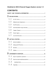
TABLE OF CONTENTS…
1
INTRODUCTION ......................................................................................................1
1.1
Scope..................................................................................................................................... 1
1.2
Important Notices................................................................................................................ 1
1.3
Intended Audience............................................................................................................... 1
1.4
Using this Manual................................................................................................................ 1
2
SAFETY PROCEDURES.............................................................................................3
3
DESIGN........................................................................................................................9
3.1
General Design..................................................................................................................... 9
3.2
Main System Assembly ..................................................................................................... 10
3.3
DO Probe Assembly .......................................................................................................... 10
3.4
DO Local Control Box (LCB) ......................................................................................... 10
3.5
Pneumatic Connections..................................................................................................... 10
3.6
Operational Principles ...................................................................................................... 11
3.7
Access to Data .................................................................................................................... 12
3.7.1
Front Panel Interface (Local Mode) ............................................................................ 12
3.7.2
Local PC Access (Serial Communications) ................................................................ 13
3.7.3
Remote PC Access ...................................................................................................... 13
4
DO TECHNICAL SPECIFICATION ...........................................................................15
5
INSTALLATION .........................................................................................................19
5.1
General Rules..................................................................................................................... 19
5.1.1
Recommended Locations ............................................................................................ 19
5.1.2
Personnel Skill Level .................................................................................................. 20
5.1.3
Test Equipment and Tools........................................................................................... 20
5.1.4
Pre-commissioning checks and tasks .......................................................................... 21
5.2
Installation of Main Electronics Panel ............................................................................ 21
5.3
Physical Installation of Local Control Box ..................................................................... 23
5.3.1
Local Control Box Pneumatics ................................................................................... 24
v
AZTEC SERIES 5000 DISSOLVED OXYGEN SYSTEM
5.4
Main Probe Assembly Installation................................................................................... 25
5.4.1
General Description..................................................................................................... 25
5.4.2
Mounting Bracket........................................................................................................ 26
5.4.3
Support Pole ................................................................................................................ 28
5.4.4
Types of DO wet end Assembly ................................................................................. 28
5.5
Assembly of Makareth DO wet end.................................................................................. 30
5.5.1
Fitting the pneumatic cylinder to the plastic (ABS) pole............................................ 30
5.5.2
Fitting the sensor extension to the pole assembly ....................................................... 30
5.5.3
Fitting the sensor head and cable to the sensor extension........................................... 31
5.5.4
Fitting the Makareth DO Cell ..................................................................................... 31
5.5.5
Fitting the calibration shroud/ball ............................................................................... 33
5.5.6
Connecting the pneumatic tubes ................................................................................. 34
5.5.7
Sealing the pole (Makareth wet end only) .................................................................. 34
5.5.8
Securing the pneumatic blue tube and the sensor cable .............................................. 35
5.5.9
Air Supply ................................................................................................................... 35
5.6
Assembly of Clark DO wet end......................................................................................... 37
5.6.1
Fitting the pneumatic cylinder to the plastic (ABS) pole............................................ 37
5.6.2
Fitting the sensor extension to the pole assembly ....................................................... 37
5.6.3
Fitting the sensor head and cable to the sensor extension........................................... 37
5.6.4
Fitting the Clark type cell............................................................................................ 39
5.6.5
Fitting the calibration shroud/ball ............................................................................... 40
5.6.6
Connecting the pneumatic tubes ................................................................................. 40
5.6.7
Air Supply ................................................................................................................... 40
5.6.8
Fitting the plastic 90° bend ......................................................................................... 40
5.7
Wiring Details................................................................................................................... 41
5.7.1
Power Connections...................................................................................................... 41
5.7.2
Main System Assembly and Local Control Box interconnections ............................. 43
5.7.3
Sensor cable connection .............................................................................................. 51
5.8
6
Pneumatics Connections ................................................................................................... 51
COMMISSIONING PROCEDURE .............................................................................53
6.1
Pre-commissioning checks................................................................................................ 53
6.2
Power up............................................................................................................................. 55
7
7.1
OPERATION ..............................................................................................................59
Normal mode of operation................................................................................................ 60
7.2
DO Autocalibration / Clean Cycle ................................................................................... 64
7.2.1
Autocalibration Cycle ................................................................................................. 64
7.2.2.
Cleaning Cycle ............................................................................................................ 67
vi
AZTEC SERIES 5000 DISSOLVED OXYGEN SYSTEM
7.3
8
Front Panel Operation (Local Mode) .............................................................................. 68
USING THE FRONT PANEL INTERFACE ...............................................................70
8.1
General Description .......................................................................................................... 70
8.2
Menus Available via the Main Screen ............................................................................. 73
8.3
Installation Setup Menu (Pass number 1234)................................................................. 77
8.3.1
Overview of functions accessed via the Installation Setup Menus ............................. 78
8.3.2
Installation Setup Menu – Detailed Instructions ......................................................... 79
8.4
Outputs Setup Menu (Passnumber 8888) ....................................................................... 86
8.4.1
Overview of functions accessed via the Outputs Setup Menu .................................... 87
8.4.2
Outputs Setup Menu - Detailed Instructions ............................................................... 88
8.5
Instrument Specific Setup Menu (Passnumber 3333).................................................. 101
8.5.1
Functions accessed via DO instrument-specific setup menu .................................... 102
8.5.2
DO instrument-specific setup menu – Detailed Instructions .................................... 103
8.6
General Setup Menu (Passnumber 1984)...................................................................... 111
8.6.1
Overview of functions accessed via the General Setup Menu .................................. 112
8.6.2
General Setup Menu – Detailed Instructions ............................................................ 113
8.7
Maintenance Menu (Passnumber 9999)........................................................................ 127
8.7.1
Overview of functions accessed via the Maintenance Menu .................................... 128
8.7.2
Maintenance menu – Detailed Instructions............................................................... 129
8.8
Altitude setup menu (Passnumber 1985) ...................................................................... 139
8.9
Depth of Immersion Setup Menu (Passnumber 1986)................................................. 140
8.10
Salinity Correction Setup Menu (Passnumber 1987).................................................. 141
8.11
Barometric Pressure Setup Menu (Passnumber 1988)................................................ 142
8.12
Instrument Event Menu (Passnumber 2512)................................................................ 143
Remote access - PC Connection ................................................................................................. 146
9
9.1
SERIAL COMMUNICATIONS .................................................................................147
Introduction ..................................................................................................................... 147
9.2
Connecting to the AZTEC DO System.......................................................................... 147
9.2.1
Location of interfaces................................................................................................ 149
9.3
Remote Access ................................................................................................................. 150
9.4
vii
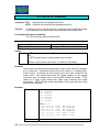
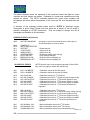
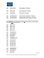
Available serial communications commands................................................................ 153
AZTEC SERIES 5000 DISSOLVED OXYGEN SYSTEM
9.4.1 List of commands (with hyperlinks) ................................................................................ 153
9.4.2 Detailed descriptions of specific comms commands ...................................................... 156
10
DO & DO-MLSS ROUTINE MAINTENANCE ......................................................249
10.1
Health & Safety ............................................................................................................... 249
10.2
Test Equipment ............................................................................................................... 249
10.3
Programmed Maintenance ............................................................................................. 249
10.4 Maintenance of the DO Wet End Assembly ................................................................. 250
10.4.1 Fitting a new Makareth cell....................................................................................... 251
10.4.2 Makareth Cell – membrane replacement .................................................................. 253
10.4.3 Fitting a new Clark cell ............................................................................................. 254
10.4.4 Changing the DO cleaning brush .............................................................................. 256
10.4.5 Re-fitting the DO calibration shroud/ball.................................................................. 256
10.4.6 Returning to normal operation .................................................................................. 257
11
FAULT DIAGNOSIS.............................................................................................259
11.1 Potential faults and their causes: ....................................................................................... 260
11.2
Event Time Stamps Accessible via the Front Panel Display. ...................................... 260
11.3
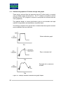
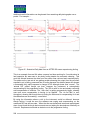
Detailed area graphs and 15-minute average data graphs.......................................... 263
DO APPENDIX A – CERTIFICATE OF CONFORMITY.................................................267
DO APPENDIX B – WARRANTY EXCLUSIONS ..........................................................268
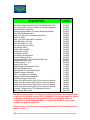
DO APPENDIX C – DO SPARE PARTS LIST ...............................................................269
SERIES 5000 COMPRESSOR ASSEMBLY ..................................................................270
DO APPENDIX D – SOFTWARE LICENCE AGREEMENT ..........................................274
**** ADDITIONAL SECTION FOR MLSS IN DO-MLSS ****..........................................275
12
MLSS IN DO/MLSS EQUIPMENT - INTRODUCTION ........................................277
12.1
Scope................................................................................................................................. 277
12.2
Product Range ................................................................................................................. 277
12.3
Intended Audience........................................................................................................... 277
viii
AZTEC SERIES 5000 DISSOLVED OXYGEN SYSTEM
12.4
Measurement Principles ................................................................................................ 277
13 MLSS EXTENSION TO DO - TECHNICAL SPECIFICATION ..................................279
14 DO-MLSS OPERATION.............................................................................................281
14.1
Normal Operational Mode ............................................................................................. 283
14.2 DO-MLSS ‘Autocalibration’ and Clean Cycles ........................................................... 284
14.2.1 ‘Autocalibration’ Cycle – N.B. only DO is actually calibrated ................................ 284
14.2.2 Clean Cycle ............................................................................................................... 285
14.3
DO-MLSS Font Panel Operation (Local Mode)........................................................... 286
15
USING THE FRONT PANEL INTERFACE..........................................................289
15.1
General Description ........................................................................................................ 289
15.2
Menus Available via the Main Screen ........................................................................... 290
15.3 DO-MLSS Installation Setup Menu (Passnumber 1234)............................................. 291
15.3.1 Overview of functions accessed via the INSTALLATION SETUP Menus............. 292
15.4
Instrument-Specific Setup (passnumber ‘3333’).......................................................... 293
16
ADDITIONAL SS-RELATED SERIAL COMMANDS ..........................................297
17
DO-MLSS ROUTINE MAINTENACE...................................................................301
17.1
Health & Safety ............................................................................................................... 301
17.2
Test Equipment ............................................................................................................... 301
17.3
Programmed Maintenance ............................................................................................. 301
17.4
Maintenance of the DO- MLSS Wet End Assembly .................................................... 302
17.5 MLSS Measuring System sensor head and amplifier .................................................. 303
17.5.1 Materials and Equipment required: ........................................................................... 303
17.5.2 MLSS Sensor calibration - Method........................................................................... 303
APPENDIX E – DO-MLSS WARRANTY EXCLUSIONS ...............................................305
APPENDIX F – DO-MLSS: SPARE PARTS LIST FOR MLSS COMPONENTS...........306
APPENDIX G – TERMINAL DESIGNATIONS, DO-MLSS ............................................307
ix
AZTEC SERIES 5000 DISSOLVED OXYGEN SYSTEM
APPENDIX H – EXAMPLE MSDS FOR FORMAZIN TURBIDITY STANDARD ...........308
INDEX .....................................................................ERROR! BOOKMARK NOT DEFINED.
SEVERN TRENT SERVICES INTERNATIONAL OFFICES ..........................................323
x
AZTEC SERIES 5000 DISSOLVED OXYGEN SYSTEM
TABLE OF FIGURES
Figure 1 - Typical arrangement of an AZTEC double DO System.................................................................................... 9
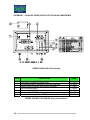
Figure 2 - System Dimensions (with optional mounting panel) – units in millimetres................................................... 17
Figure 3 - System Dimensions (with optional mounting panel & integral compressor) - units in millimetres .............. 18
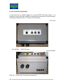
Figure 4 - Main electronics panel without integral compressor ....................................................................................... 21
Figure 5 - Main electronics module with integral compressor & optional mounting panel............................................ 22
Figure 6 - Local Control box – Front view showing buttons ........................................................................................... 23
Figure 7 - Local control box – view of base showing connectors.................................................................................... 23
Figure 8 - Diagram showing the local control box mounting arrangement ..................................................................... 24
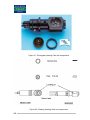
Figure 9 - Drawing showing installations of the floating ball and fixed shroud wet end DO assemblies. ..................... 25
Figure 10 - Drawing of a mounting bracket demonstrating the pivoting action by showing the pole in two positions. 26
Figure 11 - Diagram of Makareth DO Wet End Assembly.............................................................................................. 29
Figure 12 - Makareth cell and storage holder ................................................................................................................... 32
Figure 13 - Diagram showing the fitting of Makareth DO cell........................................................................................ 32
Figure 14 - Diagram of split collet for Makareth wet end................................................................................................ 34
Figure 15 – Diagram of Clark cell DO Wet End Assembly............................................................................................. 36
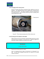
Figure 16 - Clark DO cell retaining ring key.................................................................................................................... 39
Figure 17 - Illustrations showing the fitting of the Clark DO cell ................................................................................... 39
Figure 18 - Main System Assembly showing external connections ................................................................................ 41
Figure 19 - Diagram showing mains (line) power connectors ......................................................................................... 42
Figure 20 - Diagram showing control (signal) cable between Main System Assembly and Local Control Box ........... 43
Figure 21 - 5.7.3. (i) Terminal designations for single DO instrument (with & without optional comms).................... 45
Figure 22 - 5.7.3. (ii) Terminal designations for single DO with a Local Control Box (shown overleaf)...................... 47
Figure 23 - 5.7.3. (iii) Terminal designations for double DO instrument with LCB shown overleaf............................. 49
Figure 24 - Signal cable(s) screen termination detail ....................................................................................................... 51
Figure 25 - Fuse ratings and location................................................................................................................................ 54
Figure 26 - Electronics module – front panel display and keypad................................................................................... 68
Figure 27 - Local Control Box showing layout. ............................................................................................................... 69
Figure 28 - Front panel interface electronics module (display and keypad).................................................................... 70
Figure 29 - Installation ‘1234’ menu navigation flowchart.............................................................................................. 77
Figure 30 - Outputs setup '8888' menu navigation flowchart........................................................................................... 86
Figure 31 - Instrument-specific menu '3333' navigation flowchart................................................................................ 101
Figure 32 - General setup '1984' menu navigation flowchart......................................................................................... 111
Figure 33 - Maintenance '9999' menu navigation flowchart .......................................................................................... 127
Figure 34 - Flowchart showing DO zeroing (ZDO) display sequence .......................................................................... 137
Figure 35 - RS232 communication connection to the Electronics Module ................................................................... 147
Figure 36 - Communications interface location ............................................................................................................. 149
Figure 37 - Diagram of typical installations of floating ball and fixed shroud wet end assemblies ............................. 250
Figure 38 - Diagram showing the fitting of a Makareth cell .......................................................................................... 252
Figure 39 - Drawing of a Makareth cell with membrane ready to be trimmed. ............................................................ 254
Figure 40 - Photograph showing Clark cell assembly .................................................................................................... 254
Figure 41 - Photograph showing Clark cell components ............................................................................................... 255
Figure 42 - Drawing showing Clark cell components .................................................................................................... 255
Figure 43 - Photograph showing cleaning brush (Clark cell wet end)........................................................................... 256
Figure 44 - Example calibration detailed area graph shapes .......................................................................................... 263
Figure 45 - Illustrative Daily data from an AZTEC DO sensor experiencing fouling .................................................. 264
Figure 46 - Specification for Wet End MLSS and MLSS extension to DO instrument................................................ 279
Figure 47 - DO/SS electronics module – front panel interface ...................................................................................... 286
Figure 48 - DO-SS Local Control Box showing layout. ............................................................................................... 287
Figure 49 - Flowchart for setting MLSS ’ZSS’ .............................................................................................................. 294
Figure 50 - Combined DO + MLSS. sensor head showing MLSS components............................................................ 302
Figure 51 - DO-MLSS cable splitter fitted on main electronics panel........................................................................... 302
Figure 52 - MLSS amplifier showing setup components ............................................................................................... 304
Figure 53 - Location of MLSS amplifier board and cable splitter in DO-MLSS product............................................. 307
xi
AZTEC SERIES 5000 DISSOLVED OXYGEN SYSTEM
1
INTRODUCTION
1.1
Scope
This manual describes the installation and maintenance of the AZTEC Series
5000 Dissolved Oxygen (DO) System with or without additional MLSS
measurement. Section 12 onwards provides extra information relating to the
instrument featuring additional MLSS measurement. These sections can be
ignored by users of DO–only instruments.
The manual includes information to enable safe and continuing operation of the
equipment. The manual should be read and understood before the equipment is
placed into service.
1.2
1.3
Important Notices
1.
SEVERN TRENT SERVICES reserve the right to make engineering
refinements to the equipment that may not be described herein. Any
questions that cannot be answered specifically by these instructions should
be addressed to SEVERN TRENT SERVICES or their agents for response.
2.
SEVERN TRENT SERVICES will not accept responsibility for any
equipment supplied or the actions of such equipment or associated system
when the customer has made a modification that is considered by SEVERN
TRENT SERVICES to be detrimental to the operation of the equipment.
Intended Audience
This manual is for reference by all scientific, operation or engineering staff using
the equipment.
1.4
Using this Manual
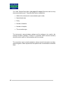
This manual contains an initial eleven chapters relevant to DO-only and common
features of DO-only and DO/MLSS instruments. These eleven chapters comprise
this introduction and ten others:
♦ Safety Procedures – outlines steps that should be taken to ensure safe use of
the equipment. This section must be read prior to installation.
♦ Design – gives a brief description of the AZTEC Dissolved Oxygen System
and the function it performs.
1
AZTEC SERIES 5000 DISSOLVED OXYGEN SYSTEM
♦ Specification – provides technical details of the AZTEC Dissolved Oxygen
System.
♦ Installation – describes the recommended method of installation.
♦ Commissioning – provides commissioning details of the AZTEC Dissolved
Oxygen System.
♦ Operation – describes the operating modes.
♦ Front Panel Access – describes the access menus and how to use them.
♦ Serial Communications – gives a listing of relevant serial interface
commands and their use and meaning.
♦ Routine Maintenance - describes all routine user maintenance tasks.
♦ Fault Finding – general statement concerning fault diagnosis and reference to
user manual.
In addition, there are four appendices for DO-only instruments:
♦ Appendix A – Certificate of Conformity
♦ Appendix B – Warranty Exclusions
♦ Appendix C – Spare Parts List
♦ Appendix D – Software Licence Agreement
Following these appendices in sections twelve onwards are the additional sections
relating specifically to MLSS in DO/MLSS combined instruments
2
AZTEC SERIES 5000 DISSOLVED OXYGEN SYSTEM
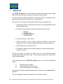
2
SAFETY PROCEDURES
The recommended installation and operating procedures have been designed with
careful attention to safety. Severn Trent Services has made formal safety
reviews of the initial design and any subsequent changes. This procedure is
followed for all new products and covers areas in addition to those included in
applicable safety standards.
The following safety precautions should be observed:
1. Observe all safety warnings marked on the equipment. These warnings
identify areas of immediate hazard, which could result in personal injury or
loss of life.
2. Do not use this equipment for any other purpose other than described in this
manual.
3. Only suitably qualified personnel should carry out work on this equipment.
4. Disconnect power to the apparatus prior to making any terminal connections
within the electronics enclosures.
Note: Alarm outputs, if used, are externally powered and could be carrying
mains (line) voltage. The instrument’s mains power isolator does NOT isolate
these circuits. In these circumstances, the installer should provide a separate
means of isolation and supplementary warning labels
5. Do not operate the equipment with the electronics enclosure open. Operation
without the protective covers may present an electric shock hazard.
6. Use all practical safety precautions to prevent contact with energised parts of
the equipment and related circuits.
7. Use the recommended connection procedures described in the installation
section.
8. Only suitably qualified personnel should perform installation.
9. When in use, compressors, valves and pneumatic cylinders may all stop and
start automatically. Suitable caution should therefore be exercised when
working on the unit. If carrying out maintenance work on the DO sensors,
entering the maintenance (‘9999’) menu should disable the automatic mode.
3
AZTEC SERIES 5000 DISSOLVED OXYGEN SYSTEM
10. DO NOT under any circumstances insert fingers into the space between the
sensor and shroud.
11. The DO system is designed to operate in wastewater plants. Removal and
maintenance of the wet end assembly poses a potential biological hazard.
Protective clothing should be used, open wounds should be protected and skin
or mucous membrane contamination should be washed off as soon as
possible. If accidental ingestion of biomass or wastewater occurs, medical
advice should be sought immediately.
12. The AZTEC DO system is often supplied with an integral compressor. On
calibration, this may run for an extended period resulting in the motor housing
becoming hot. Care should be exercised if the compressor box is cover is
removed.
13. Makareth cells are supplied stored in a sodium sulphite solution. Refer to the
following Material Safety Data Sheets before handling.
4
AZTEC SERIES 5000 DISSOLVED OXYGEN SYSTEM
MSDS SHEET:
SODIUM SULPHITE SOLUTION – 3% to 10% w/v in water
Common Names:
SODIUM SULPHITE SOLUTION
SODIUM SULFITE SOLUTION
DO ELECTRODE STORAGE SOLUTION
MSDS Contents – Information on the topics in the list below are provided.
1.
2.
3.
4.
5.
6.
7.
PRODUCT IDENTIFICATION
COMPOSITION/INFORMATION ON INGREDIENTS
HAZARD IDENTIFICATION
FIRST AID MEASURES
FIRE FIGHTING MEASURES
HANDLING AND STORAGE
EXPOSURE CONTROL/PERSONAL PROTECTION
MATERIAL SAFETY DATA SHEET
THE FOLLOWING INFORMATION, BASED UPON CURRENT KNOWLEDGE AND
EXPERIENCE OF THE PRODUCT IS NOT EXHAUSTIVE. IT APPLIES TO THE
PRODUCT AS DEFINED BY THE SPECIFICATIONS. IN CASE OF COMBINATIONS
OF MIXTURES, ONE MUST CONFIRM THAT NO NEW HAZARDS ARE LIKELY TO
EXIST. IN ANY CASE, THE USER IS NOT EXEMPT FROM OBSERVING ALL LEGAL,
ADMINISTRATIVE AND REGULATORY PROCEDURES RELATING TO THE
PRODUCT, PERSONAL HYGIENE, AND INTEGRITY OF THE WORK ENVIRONMENT.
(UNLESS NOTED TO THE CONTRARY, THE TECHNICAL INFORMATION APPLIES
ONLY TO PURE PRODUCT).
5
AZTEC SERIES 5000 DISSOLVED OXYGEN SYSTEM
1.
PRODUCT IDENTIFICATION
1.1 PRODUCT NAME: SODIUM SULPHITE SOLUTION;
1.2 CHEMICAL NAME: INORGANIC SODIUM COMPOUNDS.
1.3 SYNONYMS: DO ELECTRODE STORAGE SOLUTION.
2.
COMPOSITION / INFORMATION ON INGREDIENTS
CONSISTS OF AN AQUEOUS SOLUTION CONTAINING TYPICALLY 3g BUT
POSSIBLY UP TO 10g ANHYDROUS SODIUM SULPHITE PER 100 ml WATER.
DECOMPOSES IN AIR TO SODIUM SULPHATE BY ABSORPTION OF
OXYGEN.
3.
HAZARD IDENTIFICATION
3.1 ANHYDROUS SOLID SODIUM SULPHITE IS AN ODOURLESS, FREE
FLOWING WHITE CRYSTAL. ITS SOLUTION IN WATER IS USED AS A
STORAGE MEDIUM FOR SENSORS REQUIRING AN OXYGEN-FREE
STORAGE ENVIRONMENT.
3.2 ROUTE(S) OF ENTRY:
INHALATION?
SKIN?
INGESTION?
NO
YES
YES
3.3 EFFECTS OF EXPOSURE:
MAY CAUSE IRRITATION
EYES:
MAY CAUSE IRRITATION
SKIN:
MAY CAUSE IRRITATION
INGESTION:
ORAL EXPOSURE OR SWALLOWING MAY
PRODUCE GASTROINTESTINAL UPSET,
NAUSEA OR VOMITING. INGESTION MAY BE
FATAL. SULPHITE SENSITIVE INDIVIDUALS
MAY EXPERIENCE A SEVERE ALLERGIC
REACTION.
3.4 LIBERATES SULPHUR DIOXIDE IN CONTACT WITH MINERAL ACIDS.
6
AZTEC SERIES 5000 DISSOLVED OXYGEN SYSTEM
4.
FIRST AID MEASURES
THOROUGHLY RINSE ANY SPILLAGES ON THE SKIN WITH CLEAN WATER.
IRRIGATE EYES IMMEDIATELY WITH WATER IF SPLASHED AND SEEK
MEDICAL ATTENTION.
SEEK IMMEDIATE MEDICAL ATTENTION IF INGESTED.
5.
6.
FIRE FIGHTING MEASURES
5.1
FLASH POINT:
NON-COMBUSTIBLE.
5.2
FIRE FIGHTING METHOD:
NOT APPLICABLE
5.3
AUTOIGNITION TEMPERATURE:
NOT APPLICABLE
5.4
FLAMMABILITY LIMITS:
LOWER LIMIT:
NON-FLAMMABLE
UPPER LIMIT:
NON-FLAMMABLE
5.5
UNUSUAL FIRE AND EXPLOSION HAZARDS: IF HEATED TO
DRYNESS NON-COMBUSTIBLE. SODIUM SULPHITE GENERATES
HAZARDOUS SULPHUR DIOXIDE DURING DECOMPOSITION.
5.6
COMMON EXTINGUISHING METHODS: NOT APPLICABLE
HANDLING AND STORAGE
QUANTITIES INVOLVED ARE SMALL. HOWEVER, YOU SHOULD STILL
WEAR PROTECTIVE GLOVES AND GOGGLES WHEN HANDLING.
STORE IN THE CONTAINER PROVIDED AND KEEP THE CONTAINER
CAPPED WHEN NOT IN USE.
7.
EXPOSURE CONTROL/PERSONAL PROTECTION
AVOID DIRECT OR INDIRECT CONTACT WITH THE SOLUTION. WEAR
PROTECTIVE CLOTHING, GLOVES AND EYE PROTECTION.
7
AZTEC SERIES 5000 DISSOLVED OXYGEN SYSTEM
[Section spacer page]
8
AZTEC SERIES 5000 DISSOLVED OXYGEN SYSTEM
3
DESIGN
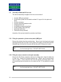
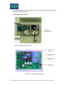
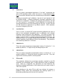
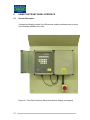
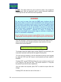
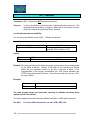
3.1
General Design
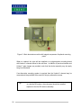
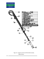
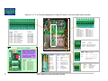
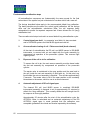
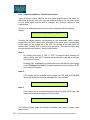
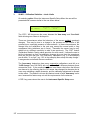
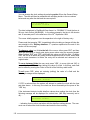
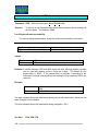
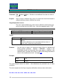
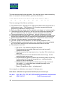
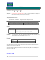
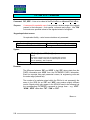
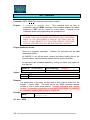
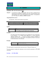
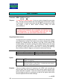
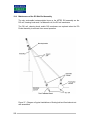
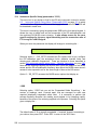
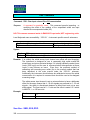
In the basic DO System there are two physically separate connected assemblies the Main System Assembly and the DO Probe Assembly.
In addition to this, where requested, a DO Local Control Box (LCB) can be
supplied. One DO Local Control Box is supplied as standard for a double DO
probe system for distributing compressed air to the additional DO probe assembly.
It enables the user to test the function of an additional DO Probe Assembly local to
the extra probe rather than at the main panel.
Main panel and 1st probe
LCB and 2nd probe
Figure 1 - Typical arrangement of an AZTEC double DO System
9
AZTEC SERIES 5000 DISSOLVED OXYGEN SYSTEM
3.2
Main System Assembly
When so ordered the Main System Assembly is normally despatched as a preassembled unit and consists of:
3.3
1.
Main backboard with Unistrut channel and pre-wired isolator
2.
Electronics Module, solenoid valves and optional compressor.
DO Probe Assembly
The DO Probe Assembly is normally despatched in a kit form with separate
assembly instructions. The DO cell is a fragile device and should be fitted during
installation/commissioning.
There may be more than one DO Probe Assembly (i.e. a double DO system)
controlled by the Main System Assembly.
The DO Probe Assembly consists of:
3.4
1.
Mounting bracket (Optional)
2.
Support pole (Optional)
3.
Wet end assembly (fixed to end of support pole)
DO Local Control Box (LCB)
This is normally despatched as a pre-assembled unit with a mounting plate
attached. It provides all the interface hardware local to the sensor in addition to a
facility to test the mechanical operation of the cleaning and calibration components
during maintenance.
These three assemblies are described in more detail later.
3.5
Pneumatic Connections
The pneumatic tubes, which run between the assemblies, are connected with 6mm
push-fit connectors. Prior to shipping, blanking plugs (part No. 25-5089) are fitted
to the panel connectors and these should be removed immediately prior to
commissioning. It is recommended that the blanking plugs be re-fitted if the Wet
End is disconnected for extended periods. Experience has shown that some
insects use the open ends of the pneumatics to nest and consequential partial
blockage results in erratic operation.
10
AZTEC SERIES 5000 DISSOLVED OXYGEN SYSTEM
The push-fit connectors retain the pneumatic tubes by means of a barbed collet,
which tightens onto the tube if any force is exerted that could otherwise pull the
tube out.
When fitting each pneumatic tube ensure that it passes fully through the “O” ring in
the push fit connector or serious malfunctions will occur.
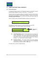
3.6
Operational Principles
The AZTEC DO system provides for the user a reliable self-cleaning,
autocalibrating dissolved oxygen measuring system, which is capable of storing 15
minute average data, including DO in % saturation and mg/l, temperature and
various other useful internally generated parameters. In addition, it stores detailed
information every time it carries out a calibration, thus enabling rapid and easy
interpretation of its condition.
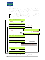
The instrument has three operating modes:
a)
Normal measuring mode
b)
Calibration and cleaning mode
c)
Manual intervention mode
For the majority of the time the instrument operates in normal operating mode,
during which time the sensor (either Clark or Makareth) responds to aqueous DO
concentrations by producing a current (microamperes) that is proportional to the
DO concentration. The current is fed into a DO head amplifier thus generating a
voltage (0 to 5 Volts) proportional to DO, which is then registered in the electronics
module via an analogue input channel.
A thermistor in the sensor head also responds to the liquor temperature. The
temperature thus recorded is used to convert the percentage saturation readings
into mg/l.
The calibration and cleaning modes are initialled either automatically at user
settable intervals, or manually via the front keypad.
11
AZTEC SERIES 5000 DISSOLVED OXYGEN SYSTEM
Cleaning of the sensor is achieved by means of a pneumatically actuated cylinder,
which pushes a shroud down over the sensor head. There is an annular brush
housed in the end of the shroud, which brushes over the face of the sensing
element as the shroud moves.
Moving the sensor into the inside of the shroud and then blowing air through the
annular space between shroud and sensor affects calibration. This is continued for
a given period to allow equilibrium to be attained, after which the reading is
adjusted to give a corrected 100% saturation value.
The manual intervention modes are accessible by typing a code on the front panel
keyboard. This will suspend normal operation and allow manual control of the
piston and aeration functions. These modes are used for maintenance and
diagnostic purposes.
Further detail of operation and the different modes is given in sections 7 and 8.
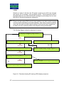
3.7
Access to Data
Three methods of data access are available:
1.
Front Panel Interface (Local Mode)
2.
Local Serial Communications Access via a PC or similar
3.
Remote Serial Communications Access via modem, PSTN and PC or
similar
3.7.1 Front Panel Interface (Local Mode)
Using the front panel interface keypad and display it is possible to check the
current state of the instrument and configure, test and alter basic aspects of its
setup. Further details on the use of the keypad can be found in section 8.
Advanced configuration of the instrument must be carried out via the serial
communications. Severn Trent Services staff should be consulted before
attempting this.
12
AZTEC SERIES 5000 DISSOLVED OXYGEN SYSTEM
3.7.2 Local PC Access (Serial Communications)
An RS232 serial port is available. A connector socket is provided for local PC
access or other suitable ASCII terminal connection. More information on serial
communications connection may be found in Section 9 Serial Communications.
Both stored fifteen-minute averages and detailed area can be recovered from the
processor onto a PC using a specially designed software suite, and the resultant
data can be displayed and manipulated in a in a variety of ways. In addition, it is
possible to access the main control program to interrogate the instrument to
determine its current operating settings or to make modifications. For further
information, please request literature on the PC Software suite (under separate
cover).
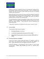
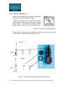
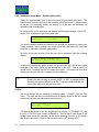
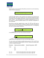
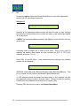
3.7.3 Remote PC Access
Exactly the same features outlined in the previous section are available remotely,
provided an error-correcting modem is connected to the serial communications
connections, and the modem is linked to the PNTN network.
Remote communications via PC, modem and PSTN
13
AZTEC SERIES 5000 DISSOLVED OXYGEN SYSTEM
[Section spacer page]
14
AZTEC SERIES 5000 DISSOLVED OXYGEN SYSTEM
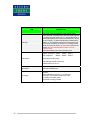
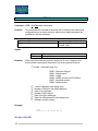
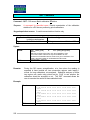
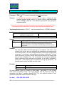
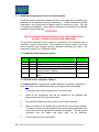
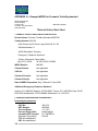
4 - DO TECHNICAL SPECIFICATION
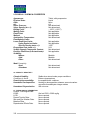
Table 1 – General Specification for the AZTEC Dissolved Oxygen System
ITEM
Compliance
Instrument parameter Ranges
The unit complies with all relevant directives of the
European Union and is CE marked to indicate this
Temperature: 0 to 50 Degrees C
DO:
0 - 130% Saturation
0 - 10 mg/l
(These are default values. Both are user re-configurable)
Measurement Principles
Temperature: Thermistor
Dissolved Oxygen: Clark Type cell or Makareth cell
Measurement Mode
Continuous
Accuracy
Analogue Outputs
Digital outputs
Serial Communications
15
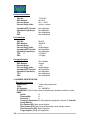
DESCRIPTION
Temperature: Better than 0.1 Deg C
Dissolved Oxygen: Better than 1% Saturation
4 – 20 mA into 1000 ohms
Four parameters, configurable
Connection via minimum of: twisted pair, individually
screened, overall screened cable.
Four (user configurable):
Each channel comprising single pole changeover
(SPCO) volt-free contact rated at 1A @ 250Vac with
internal VDR suppressers fitted. LED indication of each
relay output provided.
RS232 or as an option RS422 available. Connection via
minimum of: 3 twisted pair, individually screened, overall
screened cable
Local Display
LCD two-line, 40-character alphanumeric
Local Keypad
Numeric membrane type
Power Supply
110/120VAC or 230VAC, 50-60Hz +/- 10%
Power Consumption
300VA if integral compressor fitted, 30VA if not
Ambient operating Temperature
-10 to +50 Degrees C
Liquid operating Temperature
0 to +45 Degrees C
AZTEC SERIES 5000 DISSOLVED OXYGEN SYSTEM
ITEM
Mounting
Dimensions
DESCRIPTION
Main panel: vertical on handrails or site-specific frame
Probe assembly: A stainless steel handrail bracket supports
a 2.5 Metre long pole made from 1½” nominal ABS Class T
pressure pipe 48mm OD x 6.35mm wall thickness. This pole
has an undercut 1¼” British Standard Pipe Parallel thread
(BSPP) (11 TPI Whitworth thread form) machined one end.
The shoulder, formed by the undercut, is a sealing surface
utilised by the square section “O” ring in the end face of the
cylinder rod. THIS ARRANGEMENT MUST NOT BE
SUBSTITUTED.
All threaded fasteners ISO metric stainless steel.
Height
Width
Depth
Without compressor 880mm 400mm 269mm
With compressor
880mm 800mm 269mm
Weight approximately 27Kg
Pole assembly Normal Length 2.5m
Extended pole 3.5m or 5m
Enclosures
Air Supply
16
GRP IP67 and NEMA 4X
Pressure: nominal 2 bar max. Must be fed through a
regulator
Flow at atmospheric pressure: 1 L/s maximum
Connection: 6 mm push fit to take nylon tube
Air Quality: Instrument quality
Compressor normally provided
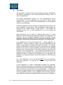
AZTEC SERIES 5000 DISSOLVED OXYGEN SYSTEM
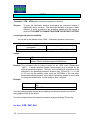
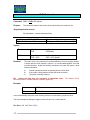
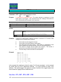
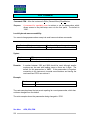
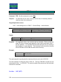
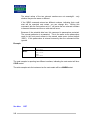
Figure 2 - System Dimensions (with optional mounting panel) – units in millimetres
17
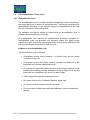
AZTEC SERIES 5000 DISSOLVED OXYGEN SYSTEM
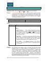
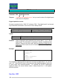
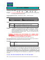
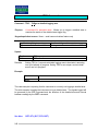
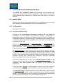
Figure 3 - System Dimensions (with optional mounting panel & integral compressor) - units in millimetres
18
AZTEC SERIES 5000 DISSOLVED OXYGEN SYSTEM
5
INSTALLATION
5.1
General Rules
It is important that the installing engineer fully reads this manual prior to
installation. To achieve successful operation, the correct installation and location
of the AZTEC DO System is vital. Incorrect installation may result in premature
life expiry of the DO Probe Assembly components and unrepresentative DO data
may be obtained.
It is important that no “short-cuts” are taken.
Analogue signal and data communications conductors must be segregated from
each other by screening, and from cables operating at different voltage
classifications. This specifically relates to the cabling from the DO Probe
Assembly, cabling from the Main System Assembly and any other plant cabling in
the vicinity of the AZTEC DO System.
Reference should be made to the Electricity Supply Regulations, the current
Edition of the IEE Wiring Regulations and supporting documents (ERA, BSI and
ISO standards publications).
Owing to the site-specific nature of process liquors, it is beyond the scope of this
document to detail exact sensor location within a process area.
SEVERN TRENT SERVICES offer to provide customer support where site-specific
advice is needed. Alternatively, SEVERN TRENT SERVICES is able to provide an
installation service. In spite of these uncertainties a number of general
installation “rules” should be considered as detailed below:
5.1.1 Recommended Locations
The installer must ensure that the AZTEC DO System assemblies are located to
provide safe and easy access for the users and maintainers of the system.
Successful existing installations have the Main System Assembly and the DO
Probe Assembly adjacent to each other, and mounted on hand railing where this
permits. The Main System Assembly when ordered is supplied with fittings to allow
direct mounting on hand railing or similar support structure. The mounting height
of the Main System Assembly should be between 1 metre and 2 metres above
local floor level and front access must not be restricted.
The protection rating of the main system unit is IP67 and care should be taken that
the installation will not compromise the integrity of the protection.
19
AZTEC SERIES 5000 DISSOLVED OXYGEN SYSTEM
It is advisable to locate the DO Probe Assembly away from areas that are known to
have:
a.
b.
c.
d.
Excessive organic growth patterns
Excessive levels of surface layer turbulence
Surface “scum/foam” accumulation.
Unrepresentative DO concentrations.
5.1.2 Personnel Skill Level
Electrical power connections must be carried out and commissioned by electrically
competent authorised personnel who are fully conversant in the requirements of
the intended installation. Instrumentation staff having at least technician status
should carry out the remaining installation.
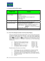
5.1.3 Test Equipment and Tools
WARNING
High voltage insulation test equipment (e.g. Megger tester) MUST
NOT BE USED on the AZTEC DO or DO/MLSS Systems – severe
damage may result and the warranty will become void.
The following tools and equipment are recommended for use during the
commissioning exercise:
a.
b.
c.
d.
Flat blade terminal screwdriver
5mm flat blade screwdriver
Multimeter (20mA / 50VDC / 500VAC / continuity range)
17mm deep-socket wrench (spanner)
With respect to the multimeter, the attention of the commissioning engineer is
drawn to the 1000-ohm maximum drive capability of the AZTEC DO System
analogue signals.
The commissioning engineer must also be aware of the need for fused test leads
for use in conjunction with any test meter, silicone grease for the Clark cell
assembly and silicone rubber for the Makareth cell assembly.
20
AZTEC SERIES 5000 DISSOLVED OXYGEN SYSTEM
5.1.4 Pre-commissioning checks and tasks
On receipt, the completeness of the AZTEC DO System should be checked
against the parts list. Any shortfall in the delivery of signs of damage should be
notified in accordance with the terms of sales/warranty.
Installation should be carried out in three parts:
a.
Physical location and installation of the main electronics panel and in
the case of a double DO system, the local control box.
b.
Assembly, location and installation of sensor assemblies
c.
Power, signal and commissioning wiring. Pneumatic tube connection
Details of the above are provided on the following pages.
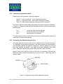
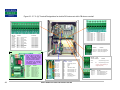
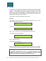
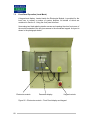
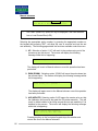
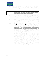
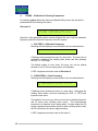
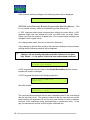
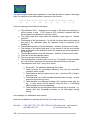
5.2
Installation of Main Electronics Panel
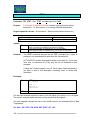
The main system unit consists of either two or three modules mounted on a single
polypropylene backboard.
The diagrams below show the typical layouts of the Main System Assembly both
with and without an integral compressor.
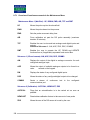
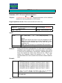
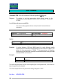
Figure 4 - Main electronics panel
without integral compressor
21
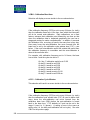
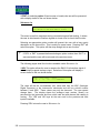
AZTEC SERIES 5000 DISSOLVED OXYGEN SYSTEM
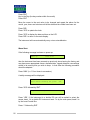
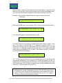
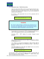
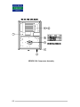
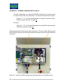
Figure 5 - Main electronics module with integral compressor & optional mounting
panel
When so ordered, the units will be supplied on a polypropylene mounting board
with Unistrut channel affixed to the rear face. In addition, a pre-wired isolator and
Unistrut pipe clamps are provided, such that the whole assembly may be easily
hung from handrails.
If an alternative mounting system is required then the Unistrut channel may be
removed and the predrilled holes used for fixing by alternative means.
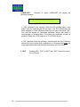
)
22
In a double-DO system, the main panel should be installed
adjacent to the first DO sensor assembly.
AZTEC SERIES 5000 DISSOLVED OXYGEN SYSTEM
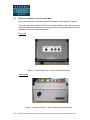
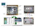
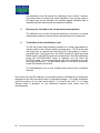
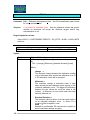
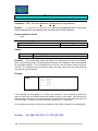
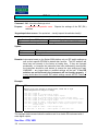
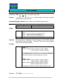
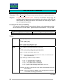
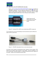
5.3
Physical Installation of Local Control Box
One local control box is normally supplied as standard with a double DO system.
The local control box contains the DO sensor head amplifier, pneumatic valves and
wiring terminals for connection to the main panel for the wet end assembly situated
remotely from the main electronics panel.
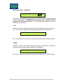
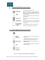
Front view
Figure 6 – Local Control box – Front view showing buttons
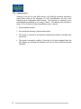
View of base
Figure 7 – Local control box – view of base showing connectors
23
AZTEC SERIES 5000 DISSOLVED OXYGEN SYSTEM
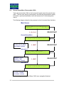
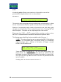
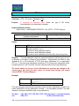
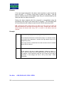
5.3.1 Local Control Box Mounting
The local control box is supplied with the mounting plate already fixed to the box.
The mounting plate should be fitted to the same mounting bracket securing the
DO Probe Assembly. The plate is supported by the two V” bolt nuts nearest the
locking wings which should be tightened down onto the mounting plate. See the
diagram below for the positioning of the box onto the handrail-clamping bolt.
Figure 8 - Diagram showing the local control box mounting arrangement
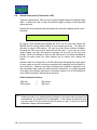
5.3.1 Local Control Box Pneumatics
The colour-coded pneumatic tubes are fitted into the push-fit connectors as shown
previously.
The air tubes from the probe are colour-coded red, green and blue.
Red
Green
Blue
-
top of pneumatic cylinder
bottom of pneumatic cylinder
aerate line down centre of support pole
The air supply, which may be from the Main System Assembly or from a site
supply, is 6 mm nylon tube to BS5409 standard.
24
AZTEC SERIES 5000 DISSOLVED OXYGEN SYSTEM
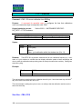
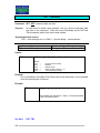
5.4
Main Probe Assembly Installation
5.4.1 General Description
When so ordered, the DO Probe Assembly will consist of the following options:
a)
b)
c)
Mounting bracket
Support Pole
Wet-end assembly (fixed to the end of the support pole)
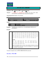
Figure 9 - Drawing showing installations of the floating ball and fixed shroud wet
end DO assemblies.
25
AZTEC SERIES 5000 DISSOLVED OXYGEN SYSTEM
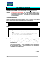
5.4.2 Mounting Bracket
The optional mounting bracket shown below is suitable for direct mounting to
handrail horizontal members of diameters up to 45mm.
The static parts are manufactured from stainless or galvanised steel and require
no maintenance.
Figure 10 - Drawing of a mounting bracket demonstrating the pivoting action by
showing the pole in two positions.
Mounting
The optional bracket, described and shown above, allows the probe assembly to
be secured to a handrail by means of an extension pole. Handrail strength must
be sufficient for both the original purpose and the additional loading imposed by
the DO Probe Assembly.
If the probe is not to be mounted on a handrail, please seek advice from
Severn Trent Services.
Bracket installation will require the use of a 17mm A/F deep socket wrench
(spanner).
To ensure correct operation of the hinged locking cams, they must move freely
without sticking or binding. Adjustment of the M6 securing nuts may be necessary.
26
AZTEC SERIES 5000 DISSOLVED OXYGEN SYSTEM
The bracket is fitted using two “V” bolts around the handrail section. The
orientation is important. The bracket mounts with the hinged locking cams on the
top site of the bracket nearest to the installer. This is to ensure that the two pins
on the pole bracket will drop into the slots and slide under gravity. The locking
cams prevent the pins moving back up the slots and disengaging from the bracket.
For systems using a pole and shroud rather than a floating ball the bracket will
need to be rotated on the handrail to ensure that the pole of the wet end is
supported at an appropriate angle.
For floating ball installations, the bracket should be rotated such that the pole can
move up and down with the ball movement without fouling on the fixed part of the
bracket.
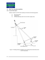
Attitude
Installation and location of the bracket and support pole must ensure free vertical
movement of the support arm as previously mentioned.
The length of the support pole plus the point of bracket fixture must ensure that:
a)
The vertical axis of the wet end assembly is 20 to 30 degrees from
true vertical to prevent air pockets developing near the DO sensor,
which can result in false measurements being made.
b)
The base of a wet end assembly is in full contact with the process
liquor and is submerged 200mm. Please contact Severn Trent
Services for advice on other depths of immersion, (for instance,
complete immersion of the cylinder and shroud for local
environmental reasons).
Minor changes to support pole length are made by adjusting the clamping position
of the bracket on the support arm. Care should be taken that such adjustments do
not result in restriction of walkway access.
For the DO Makareth type wet-end assembly the support pole is maintained at a
static pressure of 200mm of Water dependant on immersion depth and must not
be cut after installation. Pressure seal integrity may be affected if the length of the
support arm is changed by unauthorised means. This would compromise
calibrations.
27
AZTEC SERIES 5000 DISSOLVED OXYGEN SYSTEM
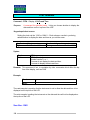
5.4.3 Support Pole
The wet end assembly support pole normally consists of one straight length of
ABS pipe and ABS pipe fittings.
The length of the straight pipe is often tailored to suit local requirements
established at time of order. To avoid excessive flexing of the support pole it is
recommended that the straight pipe length should not exceed 3.0 metres.
5.4.4 Types of DO wet end Assembly
The DO wet end assembly will be one of two types:
•
•
Makareth cell wet-end assembly
Clark cell wet-end assembly
The installation of both types is described in detail beginning overleaf.
28
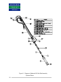
AZTEC SERIES 5000 DISSOLVED OXYGEN SYSTEM
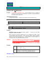
Figure 11 - Diagram of Makareth DO Wet End Assembly
* Optional Extras
29
AZTEC SERIES 5000 DISSOLVED OXYGEN SYSTEM
5.5
Assembly of Makareth DO wet end
The wet-end assembly is supplied in kit form and consists of:
•
•
•
•
•
•
•
•
•
A plastic ABS pole (optional)
A pneumatic cylinder and two black moulded ‘O’ rings to fit in the piston rod
faces
A sensor extension
A sensor mounting head and cable
A Makareth DO cell
A calibration/cleaning shroud/ball
A cable sealing collet (optional)
Assembly instructions
Pneumatic tubing (optional)
Assembly of the wet-end should be carried out as follows:
5.5.1 Fitting the pneumatic cylinder to the plastic [ABS] pole
Remove the cylinder from the protective bag. Screw it onto the thread on the pole
ensuring that the seal is in place in the groove of the piston rod and that the white
threaded ring is furthest from the pole and that the push fit fittings are in place.
)
Use firm hand tight force – DO NOT USE TOOLS
5.5.2 Fitting the sensor extension to the pole assembly
Remove the DO Sensor extension tube from the fitting pack. Keep the cable ties
for later use. Remove the thread protection cap. Ensure that the second black
seal is in place. Fit the extension tube into the cylinder (previously fitted to the
pole) ensuring that the threads are not crossed and the “O” ring makes the correct
seal.
)
30
Use firm hand tight force – DO NOT USE TOOLS
AZTEC SERIES 5000 DISSOLVED OXYGEN SYSTEM
5.5.3 Fitting the sensor head and cable to the sensor extension
Before proceeding, it is necessary to remove the split collet at the top of the pole
by unscrewing the clamping ring and removing the two halves. Put the collet in a
safe place and refit the clamping ring.
The sensor head is a black plastic component attached to 5 meters of cable fitted
with a multi pin plug. Feed the cable up the pole until the sensor head engages
with the sensor extension. The sensor head should be secured using the two M3
grub screws in the side of the extension.
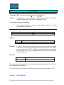
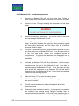
5.5.4 Fitting the Makareth DO Cell
The Makareth DO cell is supplied in a cell storage holder that contains a solution
of sodium sulphite. This ensures that the membrane remains wet and in good
condition. The membrane is delicate and may be damaged by careless use.
Inspect the electrode for signs of membrane damage and replace it if necessary.
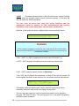
WARNING
The Makareth cell is like a battery, slowly running down as it measures
oxygen. It is supplied stored in an oxygen-absorbing solution and should be
kept in the solution when not in use. This is a 3-10% w/v solution of sodium
sulphite in water. Although only small quantities are involved, this is a
potentially hazardous chemical and must be handled appropriately. Please
refer to the example MSDS in Part 2 - Safety for further information.
The cell needs to be removed from the storage holder and attached to the DO
sensor head on the wet-end as follows:
31
AZTEC SERIES 5000 DISSOLVED OXYGEN SYSTEM
(i)
•
•
•
•
•
•
•
Removing the Makareth DO cell from its holder
Unscrew the end cap of the cell storage holder
taking care not to spill the solution inside.
Take care not to allow contact between the holder
and the DO cell.
Hold the end cap in one hand and unscrew
the knurled nut.
Whilst holding the end cap in one hand grasp
the cell with the other hand and firmly pull it away
from the end cap.
Place the cell on a smooth surface.
Unscrew the rod protruding from the end cap.
Screw the end cap back on the storage holder and
put it in a safe place in case you need to return the
cell for refurbishment.
Figure 12 - Makareth cell and storage holder
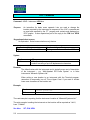
(ii)
Fitting the Makareth DO cell to the sensor head
•
Carefully screw the rod into the bottom of the
sensor head.
•
Carefully slide the cell onto the rod, align the
contact pins and push firmly home.
•
Screw the knurled nut onto the bottom of the
cell.
•
Finally, inspect the membrane for damage and
refer to the manufacturer’s instructions if
necessary.
Figure 13 - Diagram showing the fitting of Makareth DO cell
32
AZTEC SERIES 5000 DISSOLVED OXYGEN SYSTEM
5.5.5 Fitting the calibration shroud/ball
The calibration shroud or ball is supplied with a cleaning brush fitted in the bell
mouth. The brush is located in a groove, is secured by its own spring pressure,
and can easily be removed by hand if necessary.
Slide the shroud or ball over the sensor assembly taking great care to avoid
contact with the cell membrane. Ensure that the ‘O’ ring seal is against the
pneumatic cylinder and tighten the clamping ring by hand.
)
Use firm hand tight force. Do not use tools
In order to protect the Makareth DO cell when handling the probe push the
pneumatic cylinder down by hand so that the sensor is inside the calibration
shroud/ball.
33
AZTEC SERIES 5000 DISSOLVED OXYGEN SYSTEM
5.5.6 Connecting the pneumatic tubes
Please refer to the pneumatic connection diagrams…
Figure 6 – Local Control box – Front view showing buttons
Figure 7 – Local control box – view of base showing connectors
Figure 18 - Main System Assembly showing external connections
The colour-coded pneumatic tubes are fitted into the push fit connectors as shown
in Figure 11 - Diagram of Makareth DO Wet End Assembly, after first removing the
blanking plugs.
Red
Green
Blue
-
moves the sensor into the process
moves the sensor into the shroud
aerates probe for calibration
The green and red tubes must be fitted so that there is sufficient slack to allow free
movement of the pneumatic cylinder.
5.5.7 Sealing the pole (Makareth wet end only)
The probe must be sealed in order that the calibration air will reach the sensor.
The calibration must pressurise the pole to the same pressure as that exerted by
the hydrostatic head at the depth of immersion in order to displace the process
liquor and calibrate the sensor. Any leaks will prevent calibration from taking
place. Sealing is achieved using a split collet around the cable as follows:
Apply a liberal coat of silicone rubber to the collet to maintain an effective seal.
Secure the collet using the clamping ring on top of the pole. Wipe away excess
silicone rubber.
Figure 14 - Diagram of split collet for Makareth wet end
34
AZTEC SERIES 5000 DISSOLVED OXYGEN SYSTEM
5.5.8 Securing the pneumatic blue tube and the sensor cable
Loop the sensor cable and blue pneumatic tubes to the top of the pole using a
cable tie (see Figure 11 - Diagram of Makareth DO Wet End Assembly). This will
prevent any unnecessary stress on the cable and tube.
5.5.9 Air Supply
Two air-supply options are available:
(i)
(ii)
A self-contained compressor unit
Site air supply
For option (i) no further tube connections are necessary as the instrument is preassembled and tested.
For option (ii) a local site dry air supply rated at 2.0 bar should be used.
35
AZTEC SERIES 5000 DISSOLVED OXYGEN SYSTEM
16 07-5015 Retainer
16
Figure 15 – Diagram of Clark cell DO Wet End Assembly
* Optional Extras
36
AZTEC SERIES 5000 DISSOLVED OXYGEN SYSTEM
5.6
Assembly of Clark DO wet end
The wet-end assembly is supplied in a kit form and consists of:
•
•
•
•
•
•
•
•
A plastic (ABS) pole and swept bend (optional)
A pneumatic cylinder and two black moulded ‘O’ rings to fit in the piston rod
end faces
A sensor extension tube
A sensor head and cable connector
A Clark DO cell (packaged) and retaining ring key
A calibration/cleaning shroud/ball
Assembly instructions
Pneumatic tubing (optional)
Assembly of the wet-end should be carried out as per the kits enclosed assembly
instructions, which are summarised below and overleaf.
5.6.1 Fitting the pneumatic cylinder to the plastic (ABS) pole
Remove the cylinder from the protective bag. Screw it onto the thread on the pole
ensuring that the seal is in place in the groove of the piston rod and that the white
threaded ring is furthest from the pole and that the push fit fittings are in place.
)
Use firm hand tight force – DO NOT USE TOOLS
5.6.2 Fitting the sensor extension to the pole assembly
Remove the DO sensor extension tube from the fitting pack. Keep the cable ties
for later use. Remove the thread protection cap. Ensure that the second black
seal is in place. Fit the extension rube into the cylinder (previously fitted to pole)
ensuring that the threads are not crossed and the ‘O’ ring makes the correct seal.
)
Use firm hand tight force – DO NOT USE TOOLS
5.6.3 Fitting the sensor head and cable to the sensor extension
The sensor head is a plastic component fitted with a multi-pin plug for connecting
to the 5-metre long extension cable. Lubricate the “O” rings with silicone grease.
Feed the cable up the pole ensuring that it does not become twisted with the blue
pneumatic tube inside the pole. Connect the blue pneumatic line from inside the
pole to the push fit connector on the sensor head (see section 3.5 for instructions
37
AZTEC SERIES 5000 DISSOLVED OXYGEN SYSTEM
on these connectors). Screw the in-line cable connectors together. Push and
twist the sensor head into the bayonet fixture.
38
AZTEC SERIES 5000 DISSOLVED OXYGEN SYSTEM
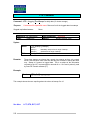
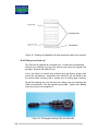
5.6.4 Fitting the Clark type cell
Remove the retaining ring from the sensor head using
the special tool provided (illustrated right).
Unpack the new Clark DO cell and install it into the
sensor head, ensuring that it locates into its mating
parts correctly. The cell block is coated in silicone
grease to repel moisture. Do not remove this grease.
Figure 16 - Clark DO cell retaining ring key
Taking care not to damage the cell membrane or transfer any silicone grease onto
the membrane, screw the retaining ring over the cell
Clark
DO Cell
Clark
DO Cell
Figure 17 - Illustrations showing the fitting of the Clark DO cell
39
AZTEC SERIES 5000 DISSOLVED OXYGEN SYSTEM
5.6.5 Fitting the calibration shroud/ball
The calibration shroud or ball is supplied with a cleaning brush fitted in the bell
mouth. The brush is located in a groove and is secured by its own spring pressure
and can easily be removed by hand if necessary.
Slide the shroud or ball over the sensor assembly taking great care to avoid
contact with the cell membrane. Ensure that the “O” ring seal is against the
pneumatic cylinder and tighten the clamping ring by hand.
)
Use firm hand tight force. Do not use tools
In order to protect the Clark DO cell when handling the probe push the pneumatic
cylinder down by hand so that the sensor is inside the calibration shroud.
5.6.6 Connecting the pneumatic tubes
Please refer to the pneumatic connection diagrams on pages 18, 29 and 36. The
colour coded pneumatic tubes are fitted into the push fit connectors as shown in
the diagram, after first removing the blanking plugs.
Red
Green
Blue
-
Moves the sensor into the process
Moves the sensor into the shroud
Aerates probe for calibration
The green and red tubes must be fitted so that there is sufficient slack to allow free
movement of the pneumatic cylinder.
5.6.7 Air Supply
Two air supply options are available:
(i)
(ii)
Self-contained compressor unit
Site air supply
For option (i) no further tube connections are necessary as the instrument is preassembled and tested.
For option (ii) a local site dry air supply rated 2.0 bar should be used.
5.6.8 Fitting the plastic 90° Bend
The 90° bend should now be fitted. Remove the bend from the fitting kit. Thread
the blue pneumatic tube and signal cable through the bend and push the bend
onto the pole ensuring that when the pole is fitted the bend faces down for
weather protection.
40
AZTEC SERIES 5000 DISSOLVED OXYGEN SYSTEM
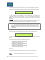
For systems supplied without a
pre-wired back panel or
compressor, please refer to
fig.21 page 44, fig.22 page 46 or
fig.23 page 48
5.7
Wiring Details
5.7.1 Power Connections
The operating voltage of the AZTEC DO System is readily confirmed from the
label attached to the equipment and will normally be either 110 Volt AC or 230 Volt
AC.
To allow for correct labelling during manufacture, and selection of the appropriate
compressor option if required, the operating voltage must be stated at the time of
order. The power supply must comply with the following requirements.
115 or 230Va.c.@50/60 Hz (+/- 10%)
The main incoming power supply cable is terminated as indicated. It is
recommended that the incoming power supply cable is armoured and should be
glanded using first quality brass glands fitted with locknuts, earth tag and PVC
over-shroud. Final cable termination is at the terminal provided at the isolator feed
side.
Pre-wired Back Panel
Three colour-coded
pneumatic tubes to DO Wet
End assembly
No pre-wired Back Panel
Plug-in connection for signal
cable from probe assembly
Power supply
cable in here
Base of electronics module
Figure 18 - Main System Assembly showing external connections
41
AZTEC SERIES 5000 DISSOLVED OXYGEN SYSTEM
Mains (line) isolator …
Isolator –
With cover removed
Live
Earth
(Ground)
Neutral
Isolator (Off)
With cover fitted
Figure 19 - Diagram showing mains (line) power connectors
42
AZTEC SERIES 5000 DISSOLVED OXYGEN SYSTEM
5.7.2 Main System Assembly and Local Control Box interconnections
This sub-section applies to double units and single with a remote probe with a
LCB
Control (Signal) cable
Pneumatic tube (black)
Figure 20 - Diagram showing control (signal) cable between Main System
Assembly and Local Control Box
Electrical:
There are no mains supply connectors for the local control box.
The signals from the sensor are connected via a pre-wired multi-way plug and socket.
The link between the electronics module and the Local Control Box requires a 12-core
screened cable connected to the terminals, and the screen itself connected to the
chassis plate.
43
AZTEC SERIES 5000 DISSOLVED OXYGEN SYSTEM
The cable recommended for the control (signal) cable is:
16/0.2 mm (0.5mm2), 12-core with overall tinned copper braided sheath and PVC outer.
R.S. Components PLC part Number 367-757, alternatively, Belden Type 9261 12 core
cable or equivalent. See section 5.7.3 for details of the terminal connections.
IMPORTANT NOTE
The digital I/O is powered internally by the instrument. It has been observed that some
Consulting Engineers have specified surge arrestors in the cabling associated with the
Local Control Box.
The power supply design of these instruments is such that the “Common” digital I/O
supply line is (NEGATIVE or MINUS) 24VDC with respect to the system 0V and each
digital output is individually held to 0V when the output is active.
THIS SHOULD BE TAKEN INTO ACCOUNT WHEN SPECIFYING ANY ANCILLARY
EQUIPMENT TO BE ATTACHED TO THIS INSTRUMENT, NOT EXPLICITLY
SPECIFIED IN THIS MANUAL.
44
AZTEC SERIES 5000 DISSOLVED OXYGEN SYSTEM
Figure 21 - 5.7.3. (i) Terminal Designations for single DO instrument (With & without optional Comms)
Main I/O
Terminal
RL0 NC
RL0 COM
RL0 NO
RL1 NC
RL1 COM
RL1 NO
RL2 NC
RL2 COM
RL2 NO
RL3 NC
RL3 COM
RL3 NO
Function
Alarm
Alarm
Alarm
Alarm
Alarm
Alarm
Alarm
Alarm
Alarm
Alarm
Alarm
Alarm
Terminal
Analogue Output – 0 +
Analogue Output – 0 Analogue Output – 1 +
Analogue Output – 1 Analogue Output – 2 +
Analogue Output – 2 Analogue Output – 3 +
Analogue Output – 3 -
Comments
1 - normally closed
1 - common
1 - normally open
2 - normally closed
2 - common
2 - normally open
3 - normally closed
3 - common
3 - normally open
4 - normally closed
4 - common
4 - normally open
Volt-free contacts
Volt-free contacts
Volt-free contacts
Volt-free contacts
Volt-free contacts
Volt-free contacts
Volt-free contacts
Volt-free contacts
Volt-free contacts
Volt-free contacts
Volt-free contacts
Volt-free contacts
Function
Analogue Output 1 +ve
Analogue Output 1 -ve
Analogue Output 2 +ve
Analogue Output 2 -ve
Analogue Output 3 +ve
Analogue Output 3 -ve
Analogue Output 4 +ve
Analogue Output 4 -ve
Terminal
Function
Mains in E
Mains in N
Mains in L
Mains (Line) supply Earth
Mains (Line) supply Neutral
Mains (Line) supply Live
With optional COMMS
CN1 and CN2 are provided to
accept incoming and outgoing
multidrop communications cable
wire tails to avoid the practice of
wiring two tails into one terminal.
Terminal
SSR +
&
SSR -
The terminals are electrically
connected by function to their
corresponding ‘partners’.
Comms I/O
Terminal
CN1 TxCN1 Tx+
CN1 RxCN1 Rx+
CN1 0V
CN2 TxCN2 Tx+
CN2 RxCN2 Rx+
CN2 0V
45
Function
Compressor supply control
(These terminals are Pre-wired on
units with integral compressor)
Function
RS422 transmit -ve
RS422 transmit +ve
RS422 receive -ve
RS422 receive +ve
RS422 signal grnd
RS422 transmit -ve
RS422 transmit +ve
RS422 receive -ve
RS422 receive +ve
RS422 signal grnd
Terminal
Dig in – 0+
Dig in – 0Dig in – 1+
Dig in – 1-
AZTEC SERIES 5000 DISSOLVED OXYGEN SYSTEM
Function
Calibration request +24V
Calibration request 0V
Uncommitted
Uncommitted
[Spacer page]
46
AZTEC SERIES 5000 DISSOLVED OXYGEN SYSTEM
Figure 22 - 5.7.3. (ii) Terminal designations for single DO with a Local Control Box (shown overleaf)
Main I/O
Terminal
RL0 NC
RL0 COM
RL0 NO
RL1 NC
RL1 COM
RL1 NO
RL2 NC
RL2 COM
RL2 NO
RL3 NC
RL3 COM
RL3 NO
Function
Terminal
Analogue Output – 0 +
Analogue Output – 0 Analogue Output – 1 +
Analogue Output – 1 Analogue Output – 2 +
Analogue Output – 2 Analogue Output – 3 +
Analogue Output – 3 -
Comments
Alarm 1 – normally closed
Alarm 1 – common
Alarm 1 – normally open
Alarm 2 – normally closed
Alarm 2 – common
Alarm 2 – normally open
Alarm 3 – normally closed
Alarm 3 – common
Alarm 3 – normally open
Alarm 4 – normally closed
Alarm 4 – common
Alarm 4 – normally open
Volt-free contacts
Volt-free contacts
Volt-free contacts
Volt-free contacts
Volt-free contacts
Volt-free contacts
Volt-free contacts
Volt-free contacts
Volt-free contacts
Volt-free contacts
Volt-free contacts
Volt-free contacts
Function
Analogue Output 1 +ve
Analogue Output 1 -ve
Analogue Output 2 +ve
Analogue Output 2 -ve
Analogue Output 3 +ve
Analogue Output 3 -ve
Analogue Output 4 +ve
Analogue Output 4 -ve
Terminal
Function
Mains in E
Mains in N
Mains in L
Mains (Line) supply Earth
Mains (Line) supply Neutral
Mains (Line) supply Live
With optional COMMS
CN1 and CN2 are provided to
accept incoming and outgoing
multidrop communications cable
wire tails to avoid the practice of
wiring two tails into one terminal.
The terminals are electrically
connected by function to their
corresponding ‘partners’.
Comms I/O
Terminal
CN1 TxCN1 Tx+
CN1 RxCN1 Rx+
CN1 0V
CN2 TxCN2 Tx+
CN2 RxCN2 Rx+
CN2 0V
47
Function
RS422 transmit -ve
RS422 transmit +ve
RS422 receive -ve
RS422 receive +ve
RS422 signal grnd
RS422 transmit -ve
RS422 transmit +ve
RS422 receive -ve
RS422 receive +ve
RS422 signal grnd
Main I/O
Terminal
Multifunction
I/O terminal
LCB
Terminal
Function
TB1 – 1B
TB1 – 5A
TB1 – 6A
TB1 – 7A
TB1 – 8A
T10
T9
T7
T8
T12
Digital supply common
Aerate
Down
Up
LCB Buttons enable
CN4 -- +ve
CN4 – 0V
CN4 -- -ve
T1
T2
T3
Head amp supply +15V
Head amp supply 0V
Head amp supply -15V
CN5 – SigA +
CN5 – Sig 0V
CN5 – SigB +
CN5 – Sig 0V
T4
T5
T6
--
DO signal +
Signal common
Temperature signal +
No connection
AZTEC SERIES 5000 DISSOLVED OXYGEN SYSTEM
LCB
Terminal
Function
SSR +
N/C
Compr. supply control
SSR -
T11*
Compr. supply control
(* Shares terminal with wiring to
integral compressor)
Terminal
Dig in – 0+
Dig in – 0Dig in – 1+
Dig in – 1-
Function
Calib request +24V
Calib request 0V
Uncommitted
Uncommitted
Pneumatic
solenoid
valves
DO head
amplifier
Non-return
valve
Sensor
connector
Signal cable
screen clamp
Multifunction
I/O terminal
LCB
Terminal
TB1 – 1B
TB1 – 5A
TB1 – 6A
TB1 – 7A
TB1 – 8A
T10
T9
T7
T8
T12
Digital supply common
Aerate
Down
Up
LCB Buttons enable
CN4 -- +ve
CN4 – 0V
CN4 -- -ve
T1
T2
T3
Head amp supply +15V
Head amp supply 0V
Head amp supply -15V
CN5 – SigA +
CN5 – Sig 0V
CN5 – SigB +
CN5 – Sig 0V
T4
T5
T6
T11
DO signal +
Signal common
Temperature signal +
Compressor on
Function
Motherboard Main
I/O terminal
SSR-
48
AZTEC SERIES 5000 DISSOLVED OXYGEN SYSTEM
UP
DOWN
(Green) (Red)
AERATE
AIR
(Blue) (from main
assembly)
Figure 23 - 5.7.3. (iii) Terminal Designations for double DO instrument with LCB shown overleaf
Main I/O
Terminal
RL0 NC
RL0 COM
RL0 NO
RL1 NC
RL1 COM
RL1 NO
RL2 NC
RL2 COM
RL2 NO
RL3 NC
RL3 COM
RL3 NO
Function
Alarm
Alarm
Alarm
Alarm
Alarm
Alarm
Alarm
Alarm
Alarm
Alarm
Alarm
Alarm
Terminal
Analogue Output – 0 +
Analogue Output – 0 Analogue Output – 1 +
Analogue Output – 1 Analogue Output – 2 +
Analogue Output – 2 Analogue Output – 3 +
Analogue Output – 3 -
Comments
1 – normally closed
1 – common
1 – normally open
2 – normally closed
2 – common
2 – normally open
3 – normally closed
3 – common
3 – normally open
4 – normally closed
4 – common
4 – normally open
Volt-free contacts
Volt-free contacts
Volt-free contacts
Volt-free contacts
Volt-free contacts
Volt-free contacts
Volt-free contacts
Volt-free contacts
Volt-free contacts
Volt-free contacts
Volt-free contacts
Volt-free contacts
Function
Analogue output 1 +ve
Analogue output 1 -ve
Analogue output 2 +ve
Analogue output 2 -ve
Analogue output 3 +ve
Analogue output 3 -ve
Analogue output 4 +ve
Analogue output 4 -ve
Terminal
Mains in E
Mains in N
Mains in L
Function
Mains (Line) supply Earth
Mains (Line) supply Neutral
Mains (Line) supply Live
With optional COMMS
CN1 and CN2 are provided to
accept incoming and outgoing
multidrop communications cable
wire tails to avoid the practice of
wiring two tails into one terminal.
The terminals are electrically
connected by function to their
corresponding ‘partners’.
Comms I/O
Terminal
CN1 TxCN1 Tx+
CN1 RxCN1 Rx+
CN1 0V
CN2 TxCN2 Tx+
CN2 RxCN2 Rx+
CN2 0V
49
Function
RS422 transmit -ve
RS422 transmit +ve
RS422 receive -ve
RS422 receive +ve
RS422 signal grnd
RS422 transmit -ve
RS422 transmit +ve
RS422 receive -ve
RS422 receive +ve
RS422 signal grnd
Main I/O
LCB
Terminal Terminal
SSR +
Multifunction
I/O terminal
LCB
Terminal
TB1 – 1B
TB1 – 5A
TB1 – 6A
TB1 – 7A
TB1 – 8A
T10
T9
T7
T8
T12
Digital supply common
Aerate
Down
Up
LCB Buttons enable
CN4 -- +ve
CN4 – 0V
CN4 -- -ve
T1
T2
T3
Head amp supply +15V
Head amp supply 0V
Head amp supply -15V
CN5 – SigA +
CN5 – Sig 0V
CN5 – SigB +
CN5 – Sig 0V
T4
T5
T6
--
DO signal +
Signal common
Temperature signal +
No connection
Function
AZTEC SERIES 5000 DISSOLVED OXYGEN SYSTEM
SSR -
Function
Compressor supply control
T11*
Compressor supply control
(* Shares terminal with wiring to
integral compressor)
Terminal
Dig in – 0+
Dig in – 0Dig in – 1+
Dig in – 1-
Function
Head 1 Calib request
Head 1 Calib request
Head 2 Calib request
Head 2 Calib request
+24V
0V
+24V
0V
Pneumatic
solenoid
valves
DO head
amplifier
Non-return
valve
Sensor
connector
Signal cable
screen clamp
Multifunction
I/O terminal
LCB
Terminal
TB1 – 1B
TB1 – 5A
TB1 – 6A
TB1 – 7A
TB1 – 8A
T10
T9
T7
T8
T12
Digital supply common
Aerate
Down
Up
LCB Buttons enable
CN4 -- +ve
CN4 – 0V
CN4 -- -ve
T1
T2
T3
Head amp supply +15V
Head amp supply 0V
Head amp supply -15V
CN5 – SigA +
CN5 – Sig 0V
CN5 – SigB +
CN5 – Sig 0V
T4
T5
T6
DO signal +
Signal common
Temperature signal +
T11
Compressor on
Function
Motherboard Main
I/O terminal
SSR-
50
AZTEC SERIES 5000 DISSOLVED OXYGEN SYSTEM
UP
DOWN
(Green) (Red)
AERATE
AIR
(Blue) (from main
assembly)
Cable screen clamp
Figure 24 - Signal cable(s) screen termination detail
)
Signal cable screens must be clamped using the fitting supplied
5.7.3 Sensor cable connection
The sensor cable connections are made into the main electronics module or the
local control box as appropriate. The connection is by means of a pre-wired multi
pole connector. The plug merely needs inserting into its mating socket and the
retaining ring tightening up to prevent moisture ingress.
5.8
Pneumatics Connections
Connect the three pneumatic tubes between the Main System Assembly and the
DO Probe Assembly. These are normally colour coded red, blue and green.
Connection is achieved using push fit connectors. Please refer to the details given
in Section 3.5 and Section 4 Technical Specification.
Pneumatic through-connectors are provided to allow ease of connection and
disconnection of the DO probe pneumatic lines from the Main System Assembly.
If a local control box is to be installed, an extra push fit connector may be fitted to
the bottom of the front panel interface box (see section 5.7.2). This is used to
provide an air supply to the local control box. The air line should be 6mm nylon
tube to BS5409 standard, colour black. Alternatively, site air may be used to
supply the system independently.
51
AZTEC SERIES 5000 DISSOLVED OXYGEN SYSTEM
[Section Spacing Page]
52
AZTEC SERIES 5000 DISSOLVED OXYGEN SYSTEM
6
COMMISSIONING PROCEDURE
6.1
Pre-commissioning checks
Following installation, the AZTEC DO System should be visually inspected for
signs of mechanical damage incurred during installation. Where damage is found
Severn Trent Services should be notified for advice on whether to proceed with
the commissioning phase. The following pre-commission checks must be carried
out BEFORE the local isolator is placed in the ON position. Check and correct as
necessary:
53
a)
The mounting of the Main System Assembly is sound.
b)
The power supply rating of AZTEC DO System is the same as the power
supply provided.
c)
Power supply terminations are secure, safe and in good condition.
d)
Supplementary and equipotential bonding conductors are securely
terminated and in good condition.
e)
Protective shrouding and covers are secured in place and in good
condition.
f)
All fuses are sound, of the correct rating and in place.
diagrams on the following page).
g)
The DO cell is fitted to the DO Probe Assembly before it is immersed in the
tank.
h)
The signal cable from the DO Probe Assembly is connected into the Main
System Assembly.
i)
The three, pneumatic tubes from the DO Probe Assembly are connected to
the corresponding pneumatic lines from the Main System Assembly.
j)
If a Local Control Box is included ensure that the air supply is connected to
the black connector. This may be from the Main System Assembly if it
contains its own compressor, or from a site air supply.
k)
The positions of the DIP (DIL) switches on the Proteus module in the main
electronics enclosure at the top right of the PCBs – refer to the section on
serial communications, DIP command
l)
Verify the DIP (DIL) switch positions (See Page 191). These will have been
set in the factory. If changed accidentally, a cold restart will be necessary.
AZTEC SERIES 5000 DISSOLVED OXYGEN SYSTEM
(See table or
The items detailed in (a) to (l) above must be verified as being satisfactory before
proceeding beyond this point.
Fuse ratings and positions
20mm 5A
fast blow fuse
Power supply (Rear [lower] PCB)
F4 20mm Anti-surge
500 mA
F2 20mm Anti-surge
500 mA
F3 20mm Anti-surge
500 mA
F1 20mm Anti-surge
250 mA
Figure 25 - Fuse ratings and location
54
AZTEC SERIES 5000 DISSOLVED OXYGEN SYSTEM
6.2
Power up
It is necessary for the instrument to know the correct date and time before logging
will occur. It also needs to know when it has a new DO sensor cell or cells
installed. If the instrument has not been powered up before, it will do this
automatically by performing a cold start. If it has been powered up before, it will
perform a warm start. It will remember the set date and time but will need to be
told if a new DO cartridge has been installed.
The procedure for both these situations is given below:
Cold Start
Clock Setting: On power up the following display requesting the user to set the
clock will appear on the front panel
Power up
Cold start
Followed by:
Please set clock
Press ‘1’ then ‘2’ then ‘3’ then ‘4’ using the keypad on the front panel
The following menu will be displayed:
1.Clock
2. Manual 3. Probe 4. Quit
Use YES/NO or Num then ENT to select
Press ‘1’ followed by ‘ENT’
The following will be displayed:
= = = Clock Menu = = =
28/01/2003
15:06:23
Position the flashing cursor on the right hand side of the number to be changed.
The cursor is moved to the right by pressing ‘YES’ and to the left by pressing ‘NO’.
Note:
In all AZTEC instruments the date is in the United Kingdom format
DD/MM/YY and the time is in 24-hour format HH:MM:SS. This format is hardcoded into the instrument’s software and cannot be changed.
55
AZTEC SERIES 5000 DISSOLVED OXYGEN SYSTEM
Press ‘ENT’
Key in the Day (the day number within the month)
Press ‘ENT’
Move the cursor to the next value to be changed and repeat the above for the
month, year, hours and minutes until all the date and time fields have been set.
Press ‘DEL’
Press ‘YES’ to update the clock
Press ‘YES’ to display the date and time on the LCD.
Press ‘DEL’ to return to the main display.
The instrument will now automatically carry out an autocalibration.
Warm Start:
If the following message is shown on power up
Power up
Warm Start
then the instrument has been powered up previously since leaving the factory and
may have some appropriate sensor characteristics, logged data and user-settings
stored in its memory that you wish to keep. In that case the following procedure
should be adopted:
Press ‘9999’ (i.e. ‘9’ four times in succession)
A safety message will be displayed:
SAFETY: Please disconnect all air
lines before handling the probe. OK?
Press ‘YES’ followed by ‘ENT’
Suspend normal operation?
Press ‘YES’. If the instrument is a double DO you will be asked to select the
sensor head. On a double-DO instrument head 1 is by the main panel; head 2 is
by the Local Control Box.
Press ‘1’ followed by ENT.
56
AZTEC SERIES 5000 DISSOLVED OXYGEN SYSTEM
Now press ‘DEL’. The following screen will be displayed:
1.Autocal 2. Newcart 3. ZDO 4.Quit
Use YES/NO or Num then ENT to select
Press ‘1’ followed by ‘ENT’:
Trigger autocal?
Press ‘YES’. Now press 2 followed by ‘ENT’.
Does the carriage have a new span?
Press ‘YES’ followed by ‘DEL’
Resume normal operation?
If the instrument is a single-DO, then press ‘YES’; if the instrument is a double-DO
then press ‘NO’ and you will be returned to the screen asking you to select a
sensor head. This time press ‘2’ followed by ‘ENT’ and repeat the above
sequence, then when asked to resume normal operation press ‘YES’.
The above procedure will ensure that the instrument recognises that it has a new
cartridge (or cartridges if double DO.) and will automatically carry out calibrations
on the head (or heads if double DO).
Even on warm starts one should check that the clock has been set correctly by
carrying out the clock set procedures as previously described. The instrument will
not log data until the clock has been set, and if set incorrectly will log data against
the wrong data or time. The software will check the entered date and time and will
reject any attempt to enter an illegal date and/or time.
When the instrument has completed its calibrations it should display either one or
two “=” signs on the right hand side of the display depending on how many
sensors it has. This will indicate that the calibration has been successful.
Please note that until this procedure has been completed any alarm signals
or analogue output signals will be invalid, and data will not be logged
correctly. It is important therefore, that any controls affected by alarm or
analogue output signals are disabled until the initial calibration cycle has
completed successfully.
)
57
The AZTEC DO System is now basically operational, but will probably
need further configuration to tailor it to individual requirements and
preferences.
AZTEC SERIES 5000 DISSOLVED OXYGEN SYSTEM
It is now time to configure the analogue and alarm outputs to tailor them to suit
individual requirements. This is done by the outputs setup menu accessed by
default by keying in ‘8888’ on the keypad. Details of the procedure are given in
section 8.
If you wish to enter corrections for altitude, depth of immersion, salinity or
barometric pressure, please refer to sections 8.8 through to 8.11.
58
AZTEC SERIES 5000 DISSOLVED OXYGEN SYSTEM
7
OPERATION
The AZTEC DO System is a self-contained modular system that provides reliable
and accurate measurement of dissolved oxygen (DO) concentration.
The system provides sufficient information to allow the operator to assess when the
probe is healthy and when the probe is in need of attention.
The processor unit located in the Electronics Module executes software that:
•
Sequentially controls the equipment involved in the DO autocalibration and
clean/exercise cycles
•
Processes sensor signals to provide the following measurements:
RAW DO
AUTOCAL DO
AUTOCAL-HELD DO
TEMPERATURE
•
Provides detection of alarm states
•
Outputs analogue values though assigned analogue output ports
appropriate to the corresponding designated analogue output parameters.
•
Enables detection of cell malfunctions
•
Provides the maintainer with prompts, display of measured values and an
operation override
The first four actions are carried out invisibly to the user by the software program
running automatically and continuously. The last action is carried out via the Front
Panel Interface keypad.
At any particular time the AZTEC DO System can be in one of three operational
states:
7.1
7.2
7.3
Normal mode of operation
DO Autocalibration / Clean cycle
Front Panel Operation (Local Mode)
The instrument normally spends the vast majority of its time in the normal mode of
operation.
The three operational states are described in more detail as follows:
59
AZTEC SERIES 5000 DISSOLVED OXYGEN SYSTEM
7.1
Normal mode of operation
During the normal mode of operation, the AZTEC DO System measures and
generates a number of different parameters. These parameters and their values
may be observed on the display of the front panel interface. The user may scroll
through the displayable parameters via the keypad ‘YES’ and ‘NO’ keys.
During the normal mode of operation of a DO instrument, or the DO part of a DOMLSS combination instrument, the software running on the processor unit
continuously loops reading in the two primary DO/temperature physical sensor
signals:
1.
‘d.o input’
This signal is derived from the DO cell after it has been fed through the
associated DO head amplifier. The parameter reflecting the output of this
amplifier is scaled in volts DC. (Note the sensor itself gives out a small (just
a few microamperes) current signal proportional to the partial pressure of
the oxygen in the medium surrounding the cell. This signal has to be
converted to a voltage to be processed by the main electronics hardware
and software.
2.
‘raw temp’
This is the non-linearised signal from the thermistor in the DO cell holder.
(Note the sensor itself has a resistance that varies with temperature. This
resistance has to be converted to a voltage to be processed by the main
electronics hardware. The software corrects for the fact the resistance of
the thermistor does not vary linearly with temperature.
From these two signals all the other signals are generated as follows:
3.
‘raw sat d.o’
This is a scaled derivative of “d.o input” representing the value of
percentage DO saturation which is span-adjusted so that 100 % saturation
read 100% only at the time that the processor unit has been told that a
“new” DO measuring cell has been fitted and only after it has calibrated
successfully. The range of this measurement is by default to 0 – 130 %
saturation, but it can be changed by the user.
4.
‘temperature’
This is the linearised and scaled derivative of “raw temp”. A look-up table is
applied to correct the non-linear characteristics of the thermistor (RTD)
used in the measuring cell holder. This signal is scaled 0 – 50 °Celsius.
60
AZTEC SERIES 5000 DISSOLVED OXYGEN SYSTEM
5.
‘autocal d.o’
This is a scaled, span-adjusted derivative of “d.o input”, representing the
value of DO saturation which, unlike “raw sat d.o”, is span-adjusted every
time a successful calibration has been completed by the processor unit.
Following a successful “new” calibration, “raw sat d.o” and “autocal d.o” will
be identical initially. Following subsequent successful calibrations, only
“autocal d.o” is adjusted. Comparing the changing ratio between “raw sat
d.o” and “autocal d.o” can provide a useful diagnostic for monitoring the
varying performance of the DO measuring cell over time. As with “raw sat
d.o” the “autocal d.o” parameter is, by default, scaled 0 - 130% saturation
but can be changed by the user.
6.
‘a.cal held d.o’
This is a ‘clone’ of “autocal DO” except that during calibration the value is
held at that calculated immediately prior to calibration and released
following a short settling time after calibration. This could be used as the
output to a control system to minimise disturbances during calibration – the
system would be fed a constant signal proportional to the last real
measured value (an average reading taken just before the instrument
entered calibration mode) while the sensor was calibrating. This parameter
too is scaled by default to 0 -130% sat.
7.
‘absolute d.o’
This is the scaled, temperature-compensated version of “autocal d.o”. It is
scaled, by default, 0 –10 mg/l but may be changed by the user.
8.
‘abs held d.o’
This is a scaled, temperature-compensated version of “autocal d.o”. It is
scaled by default to 0 -10mg/l but may be changed by the user. This is the
signal most commonly used for control purposes.
9.
‘DO at calib’
This parameter indicates the percentage saturation reached by the DO
measuring cell immediately prior to span adjustment during a calibration
cycle. Used as a diagnostic, this parameter can help determine the
continued consistent performance of the system when at or near a value of
100% over a period.
Large deviations in the value ‘DO at calib’ may indicate, for instance, a
sustained fouling which has overwhelmed the cleaning system or a
deteriorating measuring cell at the end of its useful life.
61
AZTEC SERIES 5000 DISSOLVED OXYGEN SYSTEM
10.
‘q cal a.fact’
This parameter is used to record the span adjustment factor calculated by
the software and applied to the autocal parameters following “quick” or
“short” autocalibration.
The default autocalibration method is a ‘long’ autocalibration and is
recommended, but quick calibrations may be useful in certain special
situations. The user can invoke quick autocalibrations as their preferred
method of autocalibrating.
A quick autocalibration can be completed in approximately 6 minutes, but if
quick calibrations are selected, a long autocalibration (approximately 30
minutes) will be initiated should a fixed number - 5 by default, but
adjustable by the user - of quick calibrations in a row are rejected as
unsuccessful.
Quick calibrations can be useful in situations where there is a large
difference in process liquor temperature and calibration air temperature. In
extremes, this can complicate calibration because of thermal lag and
temperature differences between the DO sensor and the thermistor that is
supposed to be reflecting the temperature affecting the DO sensor output.
Long calibrations are the recommended norm. A quick calibration is a
compromise. When a change is made to set quick calibrations as the
default, a long calibration is always performed once initially. The software
records the difference in behaviour of the DO cell between the truncated
response of the cell in the quick calibration period and the full, stabilised
response that is assured by the time allowed by aerating for the full period
decreed in the long calibration. The software then assumes that in
subsequent quick calibrations the characteristics of the DO cell would have
remained the same – that had it been allowed to go on to perform its full
calibration, the response difference would be the same as in the initial long
calibration.
For a quick calibration to work, the DO cell MUST be in good condition,
clean and responsive. An ageing DO cell will not give good quick
calibrations.
A quick calibration is in effect a deliberately truncated long calibration.
When an instrument performs a long calibration, details are logged of the
early period that would correspond to the timings for a quick calibration and
then it continues for the full period of the long calibration. It is possible to
examine the logged statistics of the comparative performance of the quick
and long calibration periods of a long calibration and so confirm whether a
quick calibration would give acceptable stability and accuracy of calibration.
62
AZTEC SERIES 5000 DISSOLVED OXYGEN SYSTEM
11.
‘l cal a.fact’
This parameter is used to record the span adjustment factor calculated by
the software and applied to the ‘autocal’ parameters following long
calibration, which is the default calibration type.
Also see the notes in (10) above. It can be instructive to compare for
relative reproducibility the ‘l cal a.fact’ and the ‘q cal a.fact’ that is also
recorded when long calibrations are used. The comparative statistics can
help to decide whether it would be feasible to use quick rather than long
calibrations in special circumstances.
12.
‘DO cal. fails’
This is calculated by the software from the number of successive calibration
failures – i.e. calibrations that have been rejected by the statistical checks
made by the software because they fail to meet the criteria, either the
default criteria or those reconfigured by the user.
This parameter’s value becomes zero whenever a calibration succeeds,
then increments with successive calibration failures, and goes back to zero
on a successful calibration. When this parameter is retrieved from the
instrument and examined graphically with the software it provides a highly
visual method of indicating circumstances where conditions within the
process may be at their most demanding for the measurement system, or
when complete failure of the autocalibration has occurred, either for
environmental (fouling) or for physical (lack of air, failure of sensor, failure of
equipment) reasons.
This parameter can be useful when assigned to alarm output or as part of a
set of grouped alarm outputs to indicate the general ‘health’ of the
instrument.
Each time all the parameters measurable or calculable by the software in the
instrument have been generated they are checked against the alarm settings and
the appropriate alarms activated. The software loops rapidly and continuously
updating its readings from the sensors; making new calculations; setting or
clearing alarms; and changing analogue outputs appropriately.
Any of the measured or calculated parameters can be directed to any of the four
analogue outputs. They can be freely assigned by the user – see Section 9 Serial
Communications.
63
AZTEC SERIES 5000 DISSOLVED OXYGEN SYSTEM
7.2
DO Autocalibration / Clean Cycle
7.2.1 Autocalibration Cycle
The autocalibration cycle is normally executed automatically once a day during a
non-critical period on, or close to, a preset base time. The user can reconfigure the
autocalibration frequency, or can manually trigger an autocalibration at any time
from the front panel via the menu system.
The processor unit takes a number of actions when an autocalibration cycle is
initiated either automatically or manually.
At predetermined time intervals for predetermined durations throughout an
autocalibration cycle, the processor unit activates outputs that trigger power
transistors to open or close the relevant pneumatic valve(s) and a solid state relay
that turns the integral compressor (if fitted) on or off.
Initiation of an autocalibration cycle
The autocalibration cycle is initiated:
64
•
Automatically during normal operation - by default once per day unless
overridden by the user
•
On a power up cold start (where memory contents have been lost or the
instrument has not been initially fully set up)
•
On a power up, warm start (where memory contents have previously been
initialised and retained), and the calibrate on power up flag is set to say the
instrument is to recalibrate in the event of a warm restart
•
Via the keypad, through the maintenance menu
•
By contact closure of the ‘Calibration Request’ digital input
•
On request via serial communications commands
•
Four hours after a failed routine daily autocalibration, unless overridden by
the user
AZTEC SERIES 5000 DISSOLVED OXYGEN SYSTEM
Fundamental autocalibration steps
All autocalibration sequences are fundamentally the same except for the final
action taken if the system has just cold started or has been told it has a new cell.
The timings described below apply to the recommended default long calibration.
The basic principles are the same for a short (quick) calibration, but the timings
differ and the autocalibration calculations differ, the cell response being
extrapolated to predict its expected response had it been allowed the full (long)
stabilisation time.
There are six control steps involved in a normal default long autocalibration cycle:
1.
Control signals are held - i.e. parameter ‘a.cal held d.o’ stays constant
and in DO-MLSS systems the held MLSS signals are held too.
2.
Air scour/brush cleaning of cell - Piston exercised (brush cleaned)
At the start of autocalibration the DO cell, and MLSS sensor in DO-MLSS
instruments, is scoured with air and wiped with the brush assembly by
compressed air operation of the pneumatic cylinder. This removes light
organic growth.
3.
Exposure of the cell to air for calibration
To expose the cell to air, the main sensor assembly must be drawn inside
the wet end assembly by compressed air operation of the pneumatic
cylinder.
The aerate valve is maintained in the open position and the area local to
the cell (inside the wet end assembly) is filled with air. At this point, any
liquid inside the wet end assembly is expelled. This will take approximately
5 seconds. The aerate valve is left in the open position so air constantly
blows down to the sensor, which is now in an air environment.
4.
Automatic adjustment of DO cell signal span
The cleaned DO cell (and MLSS sensor in combined DO-MLSS
instruments) assembly is exposed to air for approximately 30 minutes by
default for a long calibration. This normally allows the cell enough time for
its response to thoroughly stabilise.
Approximately 25 minutes after the start of the autocalibration cycle the
AUTOCAL factor is calculated and an automatic adjustment of the DO
AUTOCAL signal span is made provided that the calibration was
acceptable (passed all the criteria and checks imposed by the software).
65
AZTEC SERIES 5000 DISSOLVED OXYGEN SYSTEM
The assembly is then left exposed to calibrating air for a further 2 minutes.
This extra period is to allow easy visual inspection of any change made to
DO signal span by the software if the detailed logged calibration data is
retrieved using the data retrieval and inspection software.
5.
Returning the assembly to the normal measurement position
The calibration air is turned off and the assembly is returned to its normal
measurement position in contact with the process liquor to be measured.
6.
Termination of the autocalibration cycle.
The DO cell is then finally allowed to stabilise for a further approximately 3
minutes whilst in direct contact with the process liquor. This is to allow the
cell output time to respond and reflect the DO of the medium in which it
now finds itself. During this time, the HELD autocal DO signal (and held
MLSS signal if a DO-MLSS instrument) remains held. After this stabilisation
period the AUTOCAL-HELD signal is released, and will follow the
AUTOCAL signal. It is no longer held, and will vary in real-time in line with
the varying process DO. The held MLSS signal, if a DO-MLSS instrument,
is also fully released at this time.
The autocalibration cycle is now complete and normal mode of operation
resumes.
In the case of a quick DO calibration, the procedure above is followed but the timings are
changed and the way the autocal factor is calculated changes. For further information
refer to the notes on ‘q cal. a fact’ and in section 7.1 (10) and ‘q cal. a fact’ 7.1 (11) under
“Normal mode of operation” for the differences between quick versus long DO
autocalibrations.
66
AZTEC SERIES 5000 DISSOLVED OXYGEN SYSTEM
7.2.2. Cleaning Cycle
Cleaning of the DO cell (and MLSS sensor if a DO-MLSS combined instrument)
always takes place at the beginning of a DO autocalibration, but also more
frequently as an independent short process. The frequency of cleaning is userreconfigurable but defaults to once every 4 hours. The cleaning cycle consists of
steps (1), (2), (5) and (6) of the autocalibration cycle – namely:
67
•
Control signals are held
•
Air scour/brush cleaning of sensors takes place
•
The sensor is returned to the process measurement position, extended from
the shroud
•
The system is allowed to stabilise (3 minutes) to the new readings before the
held signals are released and allowed once more to follow real-time process
variations.
AZTEC SERIES 5000 DISSOLVED OXYGEN SYSTEM
7.3
Front Panel Operation (Local Mode)
A keypad and display, located inside the Electronics Module, is provided for the
local user to access a number of system facilities, full details of which are
contained in Section 8 - Using the front panel interface.
Unscrewing two black plastic retention screws and opening the clear front cover of
the module outwards to the left gives access to the membrane keypad. Its layout is
shown in the photograph below.
Electronics module
Parameter display
Keypad controls
Figure 26 – Electronics module – Front Panel display and keypad
68
AZTEC SERIES 5000 DISSOLVED OXYGEN SYSTEM
Local Control Box (if applicable)
A local control box is installed adjacent to a remote AZTEC DO probe location. It
is provided to house the sensor amplifier and pneumatics and allows for manual
testing of cleaning and aerating functions. The layout is shown below:
View from front
View from bottom
Figure 27 - Local Control Box showing layout.
69
AZTEC SERIES 5000 DISSOLVED OXYGEN SYSTEM
8
USING THE FRONT PANEL INTERFACE
8.1
General Description
A keypad and display located in the Electronics module provided access to many
of the facilities available to the user.
Figure 28 - Front Panel Interface Electronics Module (Display and keypad)
70
AZTEC SERIES 5000 DISSOLVED OXYGEN SYSTEM
It is possible to check the current state of the instrument and configure, test and
alter its operation.
This part of the manual describes how information may be observed and
parameters altered using the front panel keypad and display.
When in normal operation the MAIN SCREEN is displayed – something similar to
that shown below:
‘MSL_DO’ DATE=08/09/94 TIME = 15:05:20 =
temperature
10.2 deg C
This represents a typical example of the MAIN SCREEN from an AZTEC DO
System. The screen consists of three main areas:
(A) Clock Display line
(B) Parameter Display line
(C)*
(D)
Alarm active *
symbol
(C) is the autocalibration status for the first, or only head.
(D) is the autocalibration status for a second head (if present).
71
(A)
Clock Display/Status line: The current date and time settings of
the instrument are shown unless the instrument has been
reconfigured to not display the current date and time. The date and
time may be altered using the general setup menu described later.
By default the top line also shows action strings – short routine
messages generated to show when something happens to change
what the instrument is doing from time to time. The user is able to
forcibly view the current (latest) action string by pressing ‘.’ (dot /
stop / period) on the front keypad even when it is not currently
shown.
(B)
Parameter Display: This section displays the current readings
measured by the system. By pressing the ‘ENT’ or ‘DEL’ keys, the
user may scroll through the displayable parameters. The current
data for a single parameter is displayed on the second line of the
display unless the instrument has been reconfigured to not display
the current date and time. In that case, one parameter would be
displayed on the first line and the next on the second line. Other
parameters can be displayed using the ‘YES’ and ‘NO’ keys to scroll
through the displayable parameters.
AZTEC SERIES 5000 DISSOLVED OXYGEN SYSTEM
(C/D) Autocalibration Status: In the case of the DO System this display
indicates whether the last calibration was successful, and can be one
of the following symbols:
‘=’ shows that an instrument has accepted its last calibration.
‘N’ shows a NEW calibration is in progress.
‘?’ indicates a failed calibration and may also show a lower case
letter, “a” – “f”, “a” meaning one fail, “b” meaning two consecutive
fails. “c” three consecutive fails, and so on).
If an ‘X’ is displayed, it means that software has been unable to detect a
DO head – check if one is connected or the cable or connection is faulty.
At cold start-up a ‘N’ or ‘?’ symbol will always be displayed until a good
calibration is made.
Please note that the symbols described above are designed to be displayed
to provide a quick assessment of the instruments state. A “?” being
displayed does NOT mean the instrument is not working; it indicates that
the instrument is having to use a previous good set of calibration
information, which in most cases is fine, but the instrument may need
attention. The use of the ‘a’… symbols is to assess if fails are becoming
cumulative – which is a prompt that investigation is required. The default is
to show a “?” after six fails in a row.
The alarm active ‘*’ symbol is a diagnostic flag (Please see the part of the
manual describing the ‘8888’ menu).
72
AZTEC SERIES 5000 DISSOLVED OXYGEN SYSTEM
8.2
Menus Available via the Main Screen
User menus may be accessed from the MAIN SCREEN. The requirement to type
in one of a number of special 4-digit passnumbers prevents unauthorised entry by
casual users. There is no indication on the display of a passnumber being typed. If
a mistake is made when entering a passnumber, then press one of the four nonnumeric keys and then retype the correct passnumber from the beginning. Note
that the ‘ENT’ key does not need to be pressed after the passnumber has been
entered.
1.
Installation Setup Menu:
Typing the passnumber 1234 on the front panel keypad enters this menu.
This menu allows the user to:
•
•
•
2.
Alter the clock settings – date and time
Access the manual control functions (via the manual submenu).
Define the probe/cell status (via the probe menu).
Outputs Setup Menu:
Typing the passnumber 8888 on the front panel keypad enters this menu.
This menu allows the user to:
•
•
•
•
3.
Examine/configure setpoint values for alarm digital outputs
Configure any analogue outputs
Examine/configure setpoint values for group alarm digital outputs
Configure a “held DO” digital output for external control systems
Instrument Specific Setup Menu:
Typing the passnumber 3333 on the front panel keypad enters this menu.
This menu allows the user to:
73
Set the calibration and exercise frequencies
Set the type of calibration
Set the criteria that dictate if a calibration is accepted or not
AZTEC SERIES 5000 DISSOLVED OXYGEN SYSTEM
4.
General Setup Menu:
Typing the pass number 1984 on the front panel keypad enters this menu.
This menu allows the user to:
•
•
•
•
•
•
•
•
5.
Set the clock
Set the high and low values for the parameters being recorded.
(This also scales the analogue outputs)
Set the instrument address on a multidrop loop
Configure the communications ports
View the analogue input values
View the digital input status
Manually switch the digital outputs status
Test the communications facility
Maintenance Menu:
Typing the pass number 9999 on the front panel keypad enters this menu.
This menu allows the user to:
•
•
•
6.
Test the pneumatic piston
Test the aerate function
Set the piston movement delay time (PMD)
(This is the time that the compressor is allowed to run for when
moving the piston either up or down. If there is a remote sensor at a
long distance from the main panel, the PMD time may have to be
increased to allow sufficient time to pressurise the line).
Altitude Menu:
Typing the pass number 1985 on the front panel keypad enters this menu.
This menu allows the user to:
•
7.
Input the operating altitude of the instrument for sites significantly
above sea level. See section 8.8 for further details.
Depth of Immersion Menu:
Typing the pass number 1986 on the front keypad enters this menu.
This menu allows the user to:
•
74
Enter the DO sensor’s depth of immersion in the calibrating or
measuring position if significantly different from the assumed 20cm.
See section 8.9 for further details.
AZTEC SERIES 5000 DISSOLVED OXYGEN SYSTEM
8.
Salinity Menu:
Typing the pass number 1987 on the front panel keypad enters this menu.
This menu allows the user to:
•
9.
Enter the salinity of the measured medium if significantly different
from the assumed zero salinity – clean water. See section 8.10 for
further details.
Barometric Pressure Menu:
Typing the pass number 1988 on the front panel keypad enters this menu.
This menu allows the user to:
•
10.
Enter the DO sensor’s barometric pressure if significantly different
from the assumed 760mm mercury (1013 mbar). See section 8.11
for further details.
Logged Events menu:
Typing the pass number 2512 on the front panel keypad enters this menu.
This menu allows the user to:
•
75
View the last 100 significant events that have been carried out by the
instrument. See section 8.12 for further details
AZTEC SERIES 5000 DISSOLVED OXYGEN SYSTEM
[Section spacer Page]
76
AZTEC SERIES 5000 DISSOLVED OXYGEN SYSTEM
8.3
Installation Setup Menu (Pass number 1234)
Typing the passnumber 1234 on the front panel keypad enters this menu. This
menu accesses the maintenance functions and clock display. It allows testing of
the wet end assembly and/or setting up of the wet end assembly for calibration
after maintenance. The following diagram shows how these functions may be
accessed:
‘MSL_DO’ DATE=16/01/03 TIME=12:20:20
temperature
10.2 deg C
=
ENT or DEL or QUIT + ENT
1+2+3+4
1.CLOCK 2.MANUAL 3.PROBE 4.QUIT
Use YES/NO or Num then ENT to select ..
1 + ENT
1.Clock submenu
DEL or
NO + ENT
2 + ENT
Functions: CLOCK
Safety! Please disconnect all air
lines before handling the probe O.K?
YES + ENT
3 + ENT
NO / DEL
Suspend normal operation?
*
*
*** MSL Multi-Headed System***
Select DO Instrument Head: _
*** MSL Multi-Headed System***
Select DO Instrument Head: _
ENT **
2.Manual Submenu
1.UP 2.DWN 3.AIR 4.RMT 5.QUIT
Use Yes/NO or Num then ENT to select
1 / 2 / 3 / 4 + ENT
Functions: UP, DOWN,
AIR, RMT
NO
)
DEL
ENT or
DEL or
QUIT+ENT
1.AUTOCAL 2.NEWCART 3.QUIT
Use YES/NO or Num then ENT to select
DEL or
ENT or
QUIT+ENT
1 / 2 + ENT
Functions: AUTOCAL
NEWCART
Resume NORMAL operation?
*
**
ENT
3.Probe Submenu
YES
This text will not appear if only one DO sensor is installed
RMT (REMOTE) will not appear unless a local control box is installed.
Figure 29 – Installation ‘1234’ menu navigation flowchart
77
AZTEC SERIES 5000 DISSOLVED OXYGEN SYSTEM
8.3.1 Overview of functions accessed via the Installation Setup Menus
Main Screen Menu: 1.CLOCK 2.MANUAL 3.PROBE
CLOCK
Sets the system clock – required for data logging
MANUAL
Access to manual submenu: UP, DOWN, AIR, RMT
PROBE
Access to probe submenu: AUTOCAL, NEWCART
Manual Submenu: UP, DOWN, AIR, RMT
UP
Moves the probe up into the shroud/ball.
DWN (DOWN)
Moves the probe down into the process.
AIR (AERATE)
Force calibration air past the DO probe assembly (maximum
duration 30 minutes).
RMT (REMOTE)
Enables the user to operate the UP, DOWN and AERATE
functions from (if applicable) a local control box adjacent to
the remote DO probe.
Probe Submenu: 1.AUTOCAL 2.NEWCART
78
AUTOCAL
Flags that a DO autocalibration is to be carried out as soon
as possible.
NEWCART
Flags that the DO 100% calibration factors must be
recalculated at the next calibration to take account of the new
DO cell characteristics.
AZTEC SERIES 5000 DISSOLVED OXYGEN SYSTEM
8.3.2 Installation Setup Menu – Detailed Instructions
Typing the pass number 1234 on the front panel keypad enters this menu. The
maintenance functions and clock are accessed using this menu. It allows testing
of the wet end assembly and/or the setting up of the wet end assembly for
calibration after maintenance.
On initial power-up, the instrument will display the following message on the LCD
screen if the clock has not previously been set.
‘MSL_DO’ **PLEASE SET CLOCK**
temperature
10.2 deg C
N
The clock is battery-backed and therefore its settings are retained on power loss.
It may, however, require setting if the clock values drift, the battery link has been
removed, or the battery requires replacement.
On entry of the pass number 1234 the user will be presented with the following
display:
1.CLOCK 2.MANUAL 3.PROBE 4.QUIT
Use YES/NO or Num then ENT to select..
Selecting an appropriate option number will present the user with a less cryptic
message of the menu option on the second line of the LCD. This is mainly for
casual users. Pressing the ENT will select this option. This option will then drop
straight into the user function or display a further submenu.
)
Please note that on entry to a menu, if ‘DEL’ or ‘ENT’ is pressed before
Selecting an option number then a ‘QUIT’ request is assumed and the
user will be returned to the previous menu.
CLOCK
The clock settings can be changed by selecting option ‘1.CLOCK’ from the 1234
menu. The user will then be presented with a display similar to the one shown
below and may alter the date and time as required.
==== Clock Menu ====
16/01/2003
15:48:16
The date is displayed in the UK Day/Month/Year format i.e., DD/MM/YYYY and
the time in 24-hour clock format (HH/MM/SS). This format is hard coded in the
software and cannot be changed. In the above example, the time is 48 minutes
and 16 seconds past 3 o’clock in the afternoon on the 16th January 2003.
79
AZTEC SERIES 5000 DISSOLVED OXYGEN SYSTEM
The cursor initially appears over the separator to the right of the day entry. To
change the value in this field simply type in the new value using the keypad, then
press ‘YES’ when finished. A further press of ‘YES’ will move the cursor to the
right of the month field, and so on. In this way, each field may be edited. Pressing
‘DEL’ while entering a number will remove the last character typed. If no
characters are available to delete then the entry will be aborted. Pressing ‘NO’ will
move the cursor back to the left. Pressing ‘DEL’ when not entering a number in a
field will exit this menu and produce the following message:
Press YES to update clock …
08/09/1994 15:48:25
If ‘YES’ is selected then the clock will be updated with the time and date shown. In
this way, the clock can be set accurately at the press of the ‘YES’ key.
If the instrument detects invalid date/time values when setting the clock then the
following message will be displayed for a short time (NB: day incorrectly set to 44)
…
Error. clock update failed
44/04/1994 15:48:17
… indicating that no action was taken with the date/time settings shown. The user
must now re-select the clock functions and enter the time correctly.
If ‘NO’ is selected the following message will be displayed on the screen for a
short time before continuing to exit:
Aborted!
08/09/1994
15:48:25
On exit, the following question will always be displayed:
Display date/time on LCD top line?
A ‘YES’ response will make the instrument display the date and time on the MAIN
SCREEN. A ‘NO’ response will not display the date and time on the top line of the
main screen. In this case, the instrument will display two consecutive inputs on
the MAIN SCREEN. The default for the instrument is to display the date and time
on the top line of the LCD.
The user is now returned to the Main Screen.
80
AZTEC SERIES 5000 DISSOLVED OXYGEN SYSTEM
1.
MANUAL
On selection of option 2 the user will be presented with the following question:SAFETY! Please disconnect all air lines
before handling the probe O.K?
WARNING
This is a safety message to remind the user to disconnect all air lines
before removing the probe from the process otherwise the piston may
cause injury if accidentally operated.
Do not disconnect air lines if you wish only to observe the operation of
the wet end in-situ.
The user must press the ‘YES’ key followed by the ‘ENT’ key in order to proceed.
A ‘DEL’ or ‘NO’ key press will return the user to the 1234 menu.
Answering ‘YES’ will display a further question asking if you want to suspend
normal operation:
Suspend NORMAL operation?
If the ‘YES’ key is pressed, the instrument is taken off line with its current DO
signals held and the Manual submenu is displayed.
If the ‘NO’ or ‘DEL’ key is pressed the user is returned to the 1234 menu.
If the DO System has more than one DO probe then the user will be presented
with the following screen:
***MSL Multi-Headed System***
Select DO Instrument Head: _
Before proceeding with a multi-headed system, the user will need to identify the
number of the probe to be tested. Use the keypad to select the required DO probe
assembly by pressing ‘1’ or 2 as appropriate, then pressing ‘ENT’, or press ‘DEL’
to abort. If a head has been selected the Manual submenu will be displayed.
)
81
Please note that the Manual submenu is entered automatically if a
‘YES’ response is given to the “Suspend NORMAL operation” question.
AZTEC SERIES 5000 DISSOLVED OXYGEN SYSTEM
Manual submenu
1.UP 2.DWN 3.AIR
5.QUIT
4.RMT
Use YES/NO or Num then ENT to select..
)
The 4.RMT (REMOTE) option will only be displayed if the head selected
has a Local Control Box (LCB).
Selecting the appropriate option number, by pressing the appropriate number on
the keypad then pressing ‘ENT’, will allow the user to exercise and test the wet
end assembly. The following pages detail the functions available under this menu.
1. UP - Selection of option ‘1.UP’ will result in the probe moving out of the
process up into the shroud. The screen will display the following
message whilst this is happening:
Probe moving out of process...
The display will revert to Manual submenu once this operation has been
performed.
2. DWN (DOWN). Selecting option ‘2.DWN’ will move the probe down into
the process liquor. The screen will display the following message whilst
this is happening:
Probe moving in to process...
The display will again revert to the Manual submenu once this operation
has been performed.
3. AIR (AERATE). Selecting option 3.AIR opens the aerate valve so that
the calibration air forces its way past the DO probe assembly. This will
result in visible bubbled of air rising around the wet end assembly if it is
installed in the process. The screen will display the following message
whilst this is happening:
Press a key to stop aeration …
Temp = 12.2 °C; DO = 99.5 %sat
Pressing any key on the front panel keypad stops the aeration and
returns the user to the Manual submenu.
82
AZTEC SERIES 5000 DISSOLVED OXYGEN SYSTEM
)
If the user does not abort the aeration sooner, aeration is stopped automatically
after 30 minutes, just as if the user had pressed a key. This is to protect the
compressor from overheating and possible burnout through over prolonged
operation.
4. RMT (REMOTE) [If applicable]. Selection of option ‘4.RMT’ will allow
the user to operate the UP, DOWN and AERATE functions from a Local
Control Box (LCB). The screen will display the following question:
Confirm, Enter Remote Mode [YES/NO]?
A ‘NO’ response will return the user to the Manual Submenu.
A ‘YES’ response results in the following message being displayed:
*REMOTE MODE* (press any key to exit)
Air supply OFF
The user can now press the buttons on the local control box to operate
the ‘UP’, ‘DOWN’ and ‘AERATE’ functions.
)
The air supply button must be pressed and held down when any of
the other function buttons are being operated.
While the air supply button is pressed on the Local Control Box the
message shown in the bottom line will read “Air supply ON”.
Pressing any key will exit the menu and return to the Manual Submenu.
5. QUIT - Pressing ‘QUIT’ + ‘ENT’ or ‘DEL’ or ‘ENT’ on its own will cause
the following question to be displayed:
Resume NORMAL operation?
A ‘NO’ response will return the user to the Manual submenu; A ‘YES’
response returns the user to the 1234 menu from where the user can
return to the main screen using ‘DEL’ or ‘ENT’ or’ QUIT’ then ‘ENT’.
WARNING
The DO system will now make sure all probe assemblies are in the process.
This means that the pneumatic probe assemblies will operate.
83
AZTEC SERIES 5000 DISSOLVED OXYGEN SYSTEM
3. Probe
If the DO System has more than one probe assembly then selecting option
3 from the 1234 menu presents the user with the "select D.O Instrument
head" screen previously mentioned
Probe Submenu
The Probe submenu presents the user with the following display:1.AUTOCAL 2.NEWCART 3.QUIT
Use YES/NO or Num then ENT to select…
The following paragraphs describe the function of these options.
1. AUTOCAL - Selection of option 1.AUTOCAL will display the following
question:
Trigger auto-calibration?
A ‘YES’ response sets the immediate DO calibration requested software
flag. The software will see this flag become set and calibration will occur
as soon as possible, depending on what the instrument is currently doing.
This means that if any exercise/clean is in process or a calibration on
another assembly is in progress then the user must wait. Calibrations for
the same assembly cannot be queued so if the current assembly is
already in any part of a calibration cycle then a further calibration will not
occur. If the user has answered "No" to the "Calibrate if alarm active?"
question (‘8888’ menu – see page 100) then a calibration will not occur
until all alarms related to this assembly are inactive.
A ‘NO’ response clears the immediate DO calibration flag but will not stop
a calibration that is already taking place.
84
AZTEC SERIES 5000 DISSOLVED OXYGEN SYSTEM
2. NEWCART
Selection of option 2.NEWCART will display the
following message:
Does DO cartridge have a new span?
A ‘YES’ response to the question “Does the DO cartridge have a new
span?” sets the new/changed DO cell flag. If the DO cell/cartridge has
been changed or a new membrane fitted then the user must press ‘YES’.
This tells the system to recalculate calibration factors that relate to
new/changed cell characteristics. The system will recalibrate as soon as
possible (Please see ‘YES’ response of 1. AUTOCAL above).
A ‘NO’ response clears the software’s new/changed cell flag. Please be
aware that if this is done while a calibration is in progress and before the
signal span adjustment point then this assemblies ‘new’ will cancel.
3. QUIT
85
Pressing ‘DEL’, ‘ENT’ or ‘QUIT’ then ‘ENT’ returns the user to
the 1234 menu.
AZTEC SERIES 5000 DISSOLVED OXYGEN SYSTEM
8.4
Outputs Setup Menu (Passnumber 8888)
Typing the passnumber 8888 on the front panel keypad enters this menu. This lets the
user examine or configure the set point values for any alarm digital outputs and/or
configure any analogue outputs to their own particular requirements. The following
diagram shows how these functions may be accessed:
‘MSL_DO’ DATE=22/01/03
temperature
TIME=15:05:20 =
10.2 deg C
Keypresses 8 + 8 + 8 + 8
Outputs Setup Menu
1.DIG-ALS 2.ANA_OUTS 3.GALARM 4.HAL 5.Q
Use YES?NO or Num then ENT to select …
YES/NO
1 / 2 / 3 + ENT
DEL/ENT/QUIT
Functions: DIG OUTS
ANA OUTS,
GALARM
HAL
Calibrate if alarm active?
Figure 30 - Outputs Setup '8888' menu navigation flowchart
86
AZTEC SERIES 5000 DISSOLVED OXYGEN SYSTEM
8.4.1 Overview of functions accessed via the Outputs Setup Menu
DIG_ALAR
This lets the user set the alarm type and the limits for each
available alarm output channel. It provides the conventional
implementation of alarms.
See also "GALARM".
ANA_OUTS
This lets the user assignment of any one parameter of their
choosing to each of the available analogue output channels.
GALARM
This allows for setting up of a grouped alarm. This single
alarm can be triggered by any one of a group of input
conditions. Using this facility you could set up a single alarm
to fire conditional upon a group of input circumstances - For
example if the DO was below 1.0 mg/L OR the DO was above
3.0 mg/L OR the temperature was above 30 degrees Celsius
OR (etc…)
[ GALARM1;
GALARM2 ]
HAL
87
Accesses sub-menus GALARM1 and
GALARM2 that let the user set lower and
/ or upper setpoints on each input.
This lets the user designate which (if any) alarm digital output
to raise when the instrument is not in the measuring position
i.e. it is in maintenance mode or calibrating or cleaning. In this
circumstance the instrument's designated ‘HAL’ output signal
will be a sampled and held value. The alarm set up to reflect
this is called the signals’ Held ALarm output - hence "HAL"
AZTEC SERIES 5000 DISSOLVED OXYGEN SYSTEM
8.4.2 Outputs Setup Menu - Detailed Instructions
Typing the pass number 8888 on the front panel keypad enters this menu. As
mentioned previously, the user may now examine/configure the set point values
for any alarm digital outputs and/ or configure any analogue outputs to user
requirements.
On entry of a valid passnumber the user will be presented with the following
display:
1.DIG_ALS 2.ANA_OUTS 3.GALARM 4.HAL 5.Q
Use YES/NO or Num the ENT to select……
Pressing the keypad number corresponding to the appropriate option number
presents the user with a less cryptic description of the menu option corresponding
to that option on the second line of the LCD. This feature is provided mainly for
casual users. Pressing ‘ENT’ will then select this option. This option will then drop
into the selected user function. (See the notes below)
Note 1:
On entering this menu, if ‘DEL’ or ‘ENT’ is pressed before selecting an
option number then ‘QUIT’ is always assumed and the user will be returned
to the previous menu.
Pressing ‘DEL’ immediately on entering this menu will take the user straight
to the "Calibrate if in alarm?" question explained under the option ‘QUIT’
at the end of this section.
Note 2:
If the system has no available alarm outputs, the DIG_ALS and GALARM
menus will display the following messages for a few seconds:
No ALARM OUTPUTS available.
Note 3:
If the system has no available analogue outputs the ANA_OUTS menu will
display the following message for a few seconds:
No ANALOGUE OUTPUTS available
The following pages detail the functions available under each of these output
setup menus.
88
AZTEC SERIES 5000 DISSOLVED OXYGEN SYSTEM
1. DIG_ALARS
Selecting option 1 from the Outputs Setup Menu presents the user with something
similar to the following display:
ALM Input Name: Type
01: absolute d.o hi.1
LimVal
0.000
On
Y
ALC
010
‘ALM' is the alarm channel number assigned by the software in the instrument and
cannot be edited. The user can assign one of the instrument's parameter names
(Input Name) to each available alarm channel, and set the type (Type) and level of
alarm (‘LimVal’). The ALM channels are numbered sequentially from one. The
total number of channels available depends on the instrument configuration at
time of purchase.
Each field can only take a specific value or name. The ‘YES’ and ‘NO’ keys are
used to move to a field and ‘ENT’ is pressed to change its contents. Note that the
cursor is at the end of the field before it is selected and moves to the beginning
after ‘ENT’ has been pressed. See below
ALM Input Name: Type LimVal
01: absolute d.o hi
0.000
On
Y
ALC
010
Cursor is at the end of the 'input name' field before selection
ALM Input Name: Type LimVal
01: absolute d.o hi
0.000
On
Y
ALC
010
Cursor moves to the beginning of the 'input name' field after selection
The user can then scroll between available options using the ‘YES’ and ‘NO’ keys
or numeric key presses as detailed below. Use ‘ENT’ to select the required option
or ‘DEL’ to retain the old setting.
Parameter
Option selection available
Numeric Key presses + ENT
TYPE
Io.1
hi.1
Io.0
hi.0
0
1
2
3
Io.1, hi.1
Io.0, hi.0
89
:
:
if the limit is breached then set the alarm output high.
if the limit is breached then set the alarm output low.
AZTEC SERIES 5000 DISSOLVED OXYGEN SYSTEM
The limit is deemed breached if the magnitude of the signal is greater than the hi
value set as 'LimVal' for a high alarm, or less than the lo value set as 'LimVal' for a
low alarm.
LIM VAL
The Lim Val value is entered in the engineering units of the
selected signal. When the set limit value is breached the alarm
output will trigger provided that the alarm is enabled.
On
n – means No, do not enable the alarm output. Even if the alarm
condition is breached, do not modify the corresponding digital
output's state.
On
Y – Means yes, do physically activate the alarm output when the limit
is breached. Deactivate the alarm output when within or actually
equal to the set limit value.
ALC
The Alarm Limit condition Counter (ALC) provides a simple
mechanism to set the sensitivity of an alarm output. The software
continuously loops checking to see if an alarm condition has
occurred. It makes this check once per second. Each time the
checked input is found to have breached the alarm condition, it
increments a counter. Only when this counter has reached the
number set by 'ALC' will the digital output actually be changed to
reflect the alarm condition. This programmable count ensures the
alarm limit has definitely been breached and the value is just not
hovering or bouncing around its limit setting.
The default value for ALC is 10. This means that the alarm will not
actually be accepted unless the software has checked the specified
input and seen it in breach of its alarm conditions on 10 consecutive
checks. If it is in breach 9 times in a row, and on the tenth it is not,
the counter would be set back to zero and the checking process
would start from scratch. The acceptable range to which ALC can be
set to is zero to 900. It is unlikely you would need to change ALC.
Setting ALC to zero is not recommended. It would tell the software to
accept even a single transient check as a genuine breach of the
alarm conditions and if the input signal was hovering around its limit,
could result in the alarm output oscillating.
90
AZTEC SERIES 5000 DISSOLVED OXYGEN SYSTEM
When an alarm is active (on) the system shows an active alarm '*' (asterisk or star
symbol) on the top right of the front panel display and in addition will display either
<lo or >hi next to the signal if it happens to be currently showing on the LCD.
Example… With a Double-Headed Dissolved oxygen instrument currently
displaying...
'MSL_DO' DATE=22/01/03 TIME=09:07:39
autocal d.o 1
64.3% sat
=
=
Entering the '8888' menu, then selecting 1.DIG_ALS will produces something like:
ALM Input Name:
01: absolute d.o
Type
hi.1
LimVal
0.000
On
n
ALC
010
If you edited this display as described earlier to read:
ALM Input Name: Type
01: absolute d.o hi.1
LimVal
40.0
On
Y
ALC
010
You would now have set up the first available digital alarm output, number 1, such
that if the value of absolute DO in % saturation exceeded 40.0% on 10
consecutive readings, then the alarm output would be switched high. If you had
set up alarm 1 as described, and returned the instrument to the normal measuring
mode, and the autocalibrated DO on head 1 had remained at 64.3% saturation,
the LCD would now be displaying:
'MSL_DO' DATE=22/01/03 TIME=10:28:39
Autocal d.o 1 64.3 % sat
>hi
= *
=
The '*' at the right hand side of the top line indicates that one or more alarms are
currently being breached. In this example the '>hi' shows the autocal d.o head 1 is
reading above its high alarm set point, because '>hi' is being displayed to the right
of its current value. If the LCD did not happen to be currently displaying the line for
autocal d.o 1, then you would not see the '>hi'.
If you see a '*' on the top right of the display, indicating an alarm has been
breached, then it may be necessary to use the ‘YES’ and ‘NO’ keys to scroll
the display to see which particular parameter(s) have breached the alarm
setting. Do this by scrolling through looking for the text '>hi' or '<lo' against
the name of the particular parameter in breach.
91
AZTEC SERIES 5000 DISSOLVED OXYGEN SYSTEM
The preceding text has described setting up a simple high and low alarm or
alarms. There is a more complex possibility for configuration of alarms. In the
simple example of alarm setup one alarm is dedicated to one state of one input i.e. alarm 1 can be a low alarm for parameter 1; if you wanted a high alarm too for
parameter 1 you would assign a different alarm output, say alarm 2, to be a high
alarm on parameter 1.
However, using DIG_ALS in conjunction with GALARM the user can set a single
alarm output to operate on more than one alarm condition.
In earlier products, the switching state of these alarm settings could not be in
opposition. That is say
lo.1 and hi.0
\
lo.0 and hi.1
/
or
} ……. Originally never permitted
(i.e. could not be used) at the same time because no alarm rest state was defined.
For example if the alarm was off (0) if the value was below a certain number (lo.0)
and it was on (1) if it was above another certain number (hi.1), should it be on or
off when it was between these numbers? This condition represented an
indeterminate state and if the user set up alarms in this state it caused the display
of a '!<>' next to any related input signals if they were displayed. This was
intended to draw attention to the fact that conflicting or indeterminate alarm
conditions had been set up.
This condition has been partially relaxed in Series 5000 instruments. A setting of
lo.1 and hi.0
or
io.0 and hi.1
\
} … Is now permitted on the same input signal
/
via DIG_ALS and/or GALARM.
This condition has been made a special case. It will result in switching the output
on when one of the limits is breached and off when the other limit is breached.
However, when the signal reverts so it is not in breach of either limit the alarm
output will not immediately switch its state as 'normal' but will remain in the off/on
state that it is last switched to. This allows a very simple limited form of process
control to be attempted using only a single digital output…
An example follows…
92
AZTEC SERIES 5000 DISSOLVED OXYGEN SYSTEM
For example…
Let us say we have set up an alarm on an autocalibrated, held Dissolved Oxygen
signal such that we have….
lo.1 set at 1.0 mg/l
and
hi.0 set at 3.0 mg/l
\
}
/
on the same input signal
Now let us imagine that the DO level drops to 0.95 mg/l. This would turn on
(state=1) the low.1 digital alarm output that we assigned. Say this then caused an
aerator to be switched on. The DO now rises as a result; 0.99 Æ 1.00Æ1.01 mg/L.
we might now expect the aerator to be switched off again, because we are now no
longer in breach of the low (lo.1) alarm level (set at 1.0 mg/L). However, this will
not happen in this special case! The aerator would stay on. The DO would
continue to rise; 1.5 Æ 2.0 Æ 3.0 Æ 3.01 mg/L. As soon as the DO rose above
3.0 mg/L breaching the high alarm (hi.0), the digital output would be switched off
because it is set up as a hi.0 alarm. This in turn in our example would turn off the
aerator. The DO would then start to fall Æ 3.05 Æ 3.00 Æ 2.99. Again we might
expect that as soon as the DO dropped below 3.0, when we are no longer in
breach of the hi.0 alarm limit of 3.0 mg/L and that the digital output state would
revert to 1 (on). Again in this special case it would not. Only when the DO fell to
below 1.0 mg/L, to the lo.1 limit, would the digital output change to 1 (on). And so
the procedure would repeat.
As can be seen, it is possible to use a single digital alarm output to provide simple
DO control so that the DO, in this case, was maintained reasonably closely to
keep within the working range 1 to 3 mg/L.
This ends the discussion on DIG_ALARS.
To exit the alarms sub-menus, press the ‘DEL’ key to step back through the
various sub-menus until you back to the main display screen.
93
AZTEC SERIES 5000 DISSOLVED OXYGEN SYSTEM
2. ANA_OUTS
On selecting option 2 from the outputs setup menu the user will be presented with
the following display:
AOP Input [mg/l]
01: absolute DO
4mA
0.000
20mA
15.00
The analogue output channel (AOP) as perceived by the instrument cannot be
edited, but the user is able to assign any one of the instrument’s parameter names
to each of the available analogue outputs. The channels are numbered
sequentially from 01. The total number of channels available depends on the
instrument configuration at time of purchase.
Each field can only take a specific value or name. The ‘YES’ and ‘NO’ keys are
used to move to a field and ‘ENT’ is pressed to change its contents, at which point
‘YES’ and ‘NO’ will scroll between the available options. When the required option
is displayed ‘ENT’ is pressed to select it, or ‘DEL’ is pressed to retain the old
settings.
The engineering units reference provided on the top line of the display will
only change to the engineering units of the newly selected item once the user
has completed their input name selection.
)
Please DO NOT adjust the 4mA and 20mA values indiscriminately as
some of the inputs are tailored to the operation of the system.
Press ‘DEL’ when you have finished with this menu to return to the Outputs Setup
Menu
94
AZTEC SERIES 5000 DISSOLVED OXYGEN SYSTEM
3. GALARM
The GALARM sub-menu allows setting up a GROUPED ALARM. This single
physical alarm can be triggered by any one of a group of input conditions. This
gives you the ability to set up a single alarm to fire conditional upon a group of
input circumstances - for example if the DO was below 1.0 mg/l or the DO was
above 3.0 mg/l or the temperature was below 5 degrees Celsius or the
temperature was above 30 degrees Celsius or … (etc.)
[GALARM1 \
GALARM2] /
Accesses two sub-menus - GALARM1 and
GALARM2 – that let the user set lower and/or
upper setpoints on each input.
1.GALARM 2. GALARM2 3. QUIT
Use YES/NO or Num then ENT to select….
The user now has access to two very similar sub-menus. These allow the user to
set two individual alarm set points for each available input and to point them at
(assign them to) any available alarm output. Using this facility the user can
group/combine alarm conditions to meet site-specific control or alarm
requirements.
Each individual sub-menu gives the following display:
GALARM1:
INP Input [GAL1]
01:d.o input (D)
Type
hi.1
LimVal AlmOut
0.000
0
INP Input [GAL2] Type
01: d.o input (D) hi.1
LimVal AlmOut
0.000
0
GALARM2:
As can be seen they are identical except for the [GAL1] and [GAL2] reference on
the top line.
These menus let the user look at all available inputs, set up alarm limits, and
specify which alarm outputs should be activated when the limit is breached. The
alarm output number chosen (‘AlmOut’ on the right of the display) relates to the
index of the signal as shown in DIG_ALS menu. Setting an ‘AlmOut’ to zero
indicates that this entry is disabled (i.e. is never activated – it "goes nowhere").
By using the GALARM1/GALARM2 facility, for example, the user can create alarm
groups if there are not enough individual alarm outputs available. This is achieved
by assigning a number of different alarm conditions to the same single alarm
output.
95
AZTEC SERIES 5000 DISSOLVED OXYGEN SYSTEM
The reason that there are 2 menus - GALARM1 and GALARM2 is that you may
wish to set both a high alarm condition and a low alarm condition on the same
signal. If this were the case, you would use GALARM1 to set one condition, and
GALARM2 to set the other – for example:
GALARM1:
GALARM2:
INP Input [GAL2] Type
01:a.cal.do 1
hi.1
LimVal
1.0
AlmOut
1
INP Input [GAL2] Type
01:a.cal.do 1
hi.1
LimVal
3.0
AlmOut
1
This would set up a single Alarm Output (AlmOut) 1, to be switched ON (1) (types
are lo. 1 and hi. 1) when the DO was below 1.0 mg/l or it was above 3.0 mg/l. If
the DO were within 1.0 and 3.0 mg/l the alarm would be off.
Now, imagine that the temperature on this same instrument is signal number 4. If
now you scrolled through the inputs so you reached the temperature signal, and
modified the setting in GALARM1 and GALARM2 to be:
GALARM1:
GALARM2:
INP Input [GAL1] Type
04:Temperature
lo.1
LimVal
5.0
AlmOut
1
INP Input [GAL2] Type
04: Temperature hi.1
LimVal
30.0
AlmOut
1
This, in combination with the previous settings, would set up a single alarm output
(‘AlmOut’) - that numbered 1 - to be switched on (types are lo. 1 and hi. 1) when
the DO was below 1.0 mg/l or it was above 3.0 mg/l, or if the temperature was less
than 5 degrees C or if it was above 30 degrees C. If the DO was within the range
1.0 to 3.0 mg/l and the temperature was between 5 and 30 degrees C, then alarm
would be off.
Assuming you had set up alarm 1 as described, and returned the instrument to the
normal measuring mode, and the autocalibrated DO on head 1 became 0.9 mg/l
(which is less than the lo.1) alarm, but the temperature was 20 degrees C (which
is in range), then if you happened to be displaying the autocal DO signal the
display might be …
‘MSL_DO’ DATE=24/01/00 TIME=09:07:39
autocal DO 1
0.9 mg/l
<lo
= *
=
Whereas if you were displaying the temperature it would be…
‘MSL_DO’ DATE=24/01/00 TIME=09:07:39
temperature
20 deg c
= *
=
The ‘*’ at the right hand side of the top line indicates that one or more alarms have
been breached.
96
AZTEC SERIES 5000 DISSOLVED OXYGEN SYSTEM
In this example the ‘<lo’ visible with the autocal do for head 1 display shows the
autocal DO of head 1 is reading below its alarm set point. In the second example
where temperature is being displayed, because the LCD is not currently showing
the line for autocal DO 1, you would not see the ‘<lo’. If the top line displays an
asterisk at the right hand end, it means an alarm condition is active. However, you
might well need to scroll through the display to see which alarm signal has a
condition that has been breached. Note also that if you have set up a grouped
alarm, then possibly more than one signal could have breached its alarm setting.
When you see a ‘*’ on the top right of this display, indicating an alarm has been
breached, use the ‘YES’ and ‘NO’ keys to scroll the display if you want to see
which particular parameter(s) have breached the alarm setting. Scroll through
looking for the text ‘>hi’ or ‘<lo’ against the particular parameter name.
The preceding text has described the setting up of a simple high or low alarm or
alarms, either as a single or as a grouped alarm. There is a more complex
possibility for configuration of alarms. In the simple example of alarm setup one
alarm is dedicated to one state of one input – i.e. GALARM 1 can be a low alarm
for parameter 1; if you wanted a high alarm too for parameter 1 you would assign
GALARM 2 for that same signal to the same alarm output, as in the earlier
example.
Using DIG-ALS in conjunction with GALARM the user can set a single alarm
output to operate on more than one alarm condition.
In earlier AZTEC SERIES 5000 products, the switching state of these alarm
settings could not be in opposition. That is to say
lo. 1 and hi. 0
\
or
} … Originally was never permitted
lo. 0 and hi. 1
/
(i.e. could not be used) at the same time because no alarm rest state was defined.
For example if the alarm was off (0) if the value was below a certain number (lo.0)
and it was on (1) if it was above another certain number (hi.1), then should it be on
or off when it was between these numbers? This condition represented an
indeterminate state, and if the user had set up alarms in this state it caused the
display of a ‘!<>’ next to any related input signals if they were displayed. This was
intended to draw attention to the fact that conflicting or indeterminate alarm
conditions had been set up.
However, with all Series 5000 products this restriction has now been partially
relaxed. A setting of
lo. 1 and hi.0
or
lo. 0 and hi.1
\
} … is now permitted on the same input signal
/
via DIG_ALS and/or GALARM
97
AZTEC SERIES 5000 DISSOLVED OXYGEN SYSTEM
This combination of conditions has been made a special case. It will result in
switching the output ON when one of the limits is breached and OFF when the
other limit is breached. However, when the signal reverts so it is not in breach of
either limit the alarm output will NOT immediately switch state as ‘normal’ but will
remain in the off/on state that it is last switched to. This allows a very simple
limited form of control to be attempted using only a single digital output…
For example…
Let us say we have set up an alarm, or a grouped alarm, on an autocalibrated,
held Dissolved Oxygen signal such that we have…
lo.1 set at 1.0 mg/l
and
hi.0 set at 3.0 mg/l
\
}
/
on the same DO level signal
Now let us imagine that the DO level drops to 0.95 mg/l. This would turn on (state
= 1) the low.1 digital alarm we assigned. Say this then caused an aerator to be
switched on. The DO will now rise; 0.99 Æ 1.00 Æ1.01 mg/l. We might now
expect the aerator to be switched off again, because we are now no longer in
breach of the low (lo 1) alarm level (which we set at 1.0 mg/l). However, this
won’t happen in this special case! The aerator would stay on. The DO would
continue to rise; 1.5 Æ 2.0 Æ 2.9 Æ 3.0 Æ 3.01 mg/l. As soon as the DO rose
above 3.0 mg/l, breaching our high alarm setting (hi.0), then the digital output
would be switched off (because it is set up as a hi.0) alarm. This in turn in our
example would turn off the aerator. Now the DO would then start to fall; 3.05 Æ
3.00 Æ 2.99 mg/l. Again, we might expect that as soon as the DO dropped below
3.0 mg/l and we were no longer in breach of our hi.0 alarm limit of 3.0 mg/l that the
digital output state would revert to 1 (on). Again in this special case, it wouldn’t.
Only when the DO fell below 1.0 mg/l, our lo.1 limit would the digital output change
to 1 (on). And so the procedure would repeat.
As can be seen from this example, it would be possible to use a single digital
alarm output to provide simple control so that the DO, in this case, was maintained
reasonably closely to keep within the working range, in this case 1 to 3 mg/l. We
would have to make sure if we used a grouped alarm for this purpose and included
other signals as well as DO, that we were not setting up indeterminate or
conflicting states. If a condition were set up where the combination of alarm levels
and states were such that the software just could not tell whether an alarm
condition had occurred, would show ‘!<>’ indicating basically that the software
was unable to decipher what we intended by the alarm setup we had programmed!
This ends the discussion on G_ALARM. To exit the alarms submenus, press the
‘DEL’ key to step back through the various submenus until you get back to the
main display screen.
98
AZTEC SERIES 5000 DISSOLVED OXYGEN SYSTEM
4. HAL
This option allows the user to designate which (if any) alarm digital output to raise
when the instrument is not in the measuring position. In this circumstance, the
instrument’s output signal is a sampled and held value. The alarm set up to reflect
this is called the signals Held Alarm – hence ‘ HAL’.
On selecting option 4 from the Outputs Setup Menu the user will be presented with
the following display:
*** MSL Multi-Headed System ***
Select DO Instrument Head:
)
_
Reference to the multi headed DO probe system will only be shown if a
Multi-Headed DO System is installed.
Use the keypad to select the appropriate DO head and press ENT to display the
following input display:
Set alarm output for DO held alarm:
0
This prompts the user to select digital (alarm) output that the system will use to
indicate to an external control system that this sensor is not in the measuring
position (i.e. is holding its held signals). A setting of zero disables this feature.
The digital (alarm) output chosen must be available and will no longer operate as a
normal alarm even if enabled in the DIG_ALS or GALARM menus.
Please note that there is no warning if the alarm output selected is not available.
The user must re-enter the menu and check that the setting has been accepted.
To return to the Outputs menu press ‘DEL’
On exit, the following question will always be asked.
Calibrate if an alarm active?
This allows the user to decide if an active alarm inhibits DO calibrations. It stops
the control DO signal being held outside defined alarm conditions which may
adversely affect any attached control system. If the alarm outputs are being used
to provide active fault alarms then answer ‘YES’ to this question.
The default is to not calibrate if an alarm is active. The only override to this is
when a DO system loses power and on subsequent power-up has lost its memory
(cold start). In this case, it must go through a DO calibration before going back online.
99
AZTEC SERIES 5000 DISSOLVED OXYGEN SYSTEM
5.
[QUIT]
On exit, the following question will always be asked:
Calibrate if an alarm active?
This allows the user to decide if an active alarm, i.e. an alarm currently triggered,
inhibits DO calibrations. It stops the control DO signal being held outside defined
alarm conditions, which may adversely affect any attached control system.
)
If the alarm outputs are being used to provide active fault alarms then answer YES
to this question.
The default is to not calibrate if an alarm is active. The only override to this is
when a DO system loses power an on subsequent power-up has lost its memory
(code start). In this case it must go through a DO calibration before going back
on-line.
On answering YES/No to the question, the user is returned to the Main Screen.
Answering NO to this question when using alarm outputs to provide active fault
alarms can lead to a problem where an AZTEC DO system or derivative starts a
programmed clean or calibration cycle that fails to complete. Subsequently, the
instrument may fail to recover automatically.
•
This problem has occurred in unexpectedly cold weather due to the pneumatic
cylinder freezing during a clean or a calibration cycle. At the end of the cycle, the
cylinder failed to replace the sensor in the process and the resulting high DO
alarm (because the sensor remained in air) prevented further clean / calibration
cycles which would otherwise have lead to recovery.
•
The problem could occur for any other reason resulting in the cylinder sticking in
the extended or part-extended position during cleaning or calibration.
•
This problem can only occur if you have set up digital alarm output(s) and you
have answered ‘NO’ to “calibrate in alarm?” and a clean or calibrate fails part
through with the cylinder partly or fully extended.
100
AZTEC SERIES 5000 DISSOLVED OXYGEN SYSTEM
8.5
Instrument Specific Setup Menu (Passnumber 3333)
Typing the passnumber 3333 on the front panel keypad enters the instrument
specific setup menu. In the case of the intelligent DO system the user can set up
calibration and exercise frequencies, the type of calibration and its subsequent
acceptance limits.
Typical Main Screen
‘MSL_DO’ DATE=30/01/03
temperature
TIME=12:25:20 =
10.2 deg C
YES/NO
Calibrate at power up?
3+3+3+3
1.CTYPE 2.ALIMS 3.SLIMS 4.FREQS 5.QUIT
Use YES/NO or Num then ENT to select..
1 + ENT
***MSL Multi-Headed System***
Select DO Instrument Head:
***MSL Multi-Headed System***
Select DO Instrument Head: _
Sub-Menu 1
(Set calibration acceptance limits)
1.LONG LIMITS 2.QUICK LIMITS 3.QUIT
Use YES/NO or Num then ENT to select
Functions: CTYPE, SLIMS
(see table overleaf)
1/2 + ENT
3 + ENT
how many
CSC limits:
03
%err-limit
10.00
4 + ENT
Functions: LONG/QUICK LIMITS
(see table overleaf)
Sub-Menu 2
(Set calibration/exercise frequencies)
1.CAL FREQ 2.CLEAN FREQ 3.CBH 4.CYC 5.Q
Use YES/NO or Num then ENT to select ..
1/2 + ENT
Functions: CAL/CLEAN FREQ,
CBH, CYC
(see table overleaf)
Figure 31 - Instrument-specific menu '3333' navigation flowchart
101
AZTEC SERIES 5000 DISSOLVED OXYGEN SYSTEM
8.5.1 Functions accessed via DO instrument-specific setup menu
Instrument Specific Menu:
102
CYTPE, ALIMS, SLIMS, FREQS
CTYPE
Select calibration types to use
ALIMS
Access to Sub-menu 1: LONG LIMITS, QUICK LIMITS
SLIMS
Calibration Statistics failure override limits
FREQS
Access to Sub-menu 2: CAL FREQ, EXERCISE FREQ
Sub-menu 1:
(Set calibration acceptance limits)
LONG LIMITS
Set long calibration sampling limits
QUICK LIMITS
Set quick calibration sampling limits
Sub-menu 2:
(Set calibration/clean frequencies)
CAL FREQ
Set calibration frequency in hours
CLEAN FREQ
Set clean/exercise frequency in hours
CBH
Set calibration base hour
CYC
Set calibration period cycle window size.
AZTEC SERIES 5000 DISSOLVED OXYGEN SYSTEM
8.5.2 DO instrument-specific setup menu – Detailed Instructions
Typing the passnumber 3333 on the front panel keypad enters the DO instrument
specific setup menu.
The user can set up and examine specific variables and functions. In the case of
the DO system the user can set up calibration and clan/exercise frequencies, the
type of calibration and its subsequent acceptance limits.
On entry of the valid passnumber (3333), the user will be presented with the
following display:
1.CTYPE 2.ALIMS 3.SLIMS 4.FREQS 5.QUIT
Use YES/NO or Num then ENT to select
Selection of an appropriate option number will present the user with a less cryptic
description on the second line. This is mainly for the casual user. Pressing ENT
will select this option. This option will then drop straight into a user function or
display a further sub-menu.
Please note that on entry to a menu, if DEL or ENT is pressed before selecting an
option number then QUIT is always assumed and the user will be returned to the
previous menu.
The following pages detail the functions available under the Instrument Specific
Setup menus.
1.
CTYPE – Calibration Type
On selecting option 1 from the Instrument Specific Setup menu the user is
presented with a screen similar to the one shown below:
**** MSL Multi-Headed System ***
Select DO Instrument Head:
Reference to the multi headed DO probe system will only be shown if a
Multi-Headed DO System is installed.
Use the keypad to select the head required. Pressing ‘ENT’ will present the user
with the following screen:
Please select calibration type…
Current CAL TYPE: LONG(32mins Approx.)
103
AZTEC SERIES 5000 DISSOLVED OXYGEN SYSTEM
By pressing the ‘YES’ / ‘NO’ keys the user will be shown two further choices.
Please select calibration type
Current CAL TYPE: QUICK 6 mins Approx.
or
Please select calibration type…
Current CAL TYPE: QUICK if fails LONG
There are two basic types of calibration:
The standard LONG calibration which is where the DO System is brought to a
stable 100% DO environment and the system alters its characteristics to take
account of the cell’s performance during this calibration sequence.
The QUICK/SHORT calibration is where the DO System is exposed to a shorter
calibration sequence and as long as the system reaches a reproducible and
acceptable cell response the system will alter is character. Please note that a
LONG calibration is the recommended way to run the system. The quick
calibration is for control systems that cannot afford to have the probe off line for 32
minutes, but the price to pay is that the cell must be in perfect condition to give a
reliable and passable performance. This is why a third option is selectable called
QUICK and LONG where the DO System will try a QUICK calibration first but if
this fails to be acceptable then it will carry on to a LONG calibration.
An ‘ENT’ key press returns the user to the Instrument-specific setup menu.
2.
ALIMS – Acceptance Limits
On selecting option 2 from the Instrument Specific Setup menu the user will be
presented with the following:
**** MSL Multi-Headed System ***
Select DO Instrument Head: _
Reference to the multi headed DO probe system will only be shown if a
Multi-Headed DO System is installed.
Use the keypad to select the appropriate head and press ENT to enter the
following Sub-menu:
104
AZTEC SERIES 5000 DISSOLVED OXYGEN SYSTEM
Sub-menu 1
1.LONG LIMITS 2.QUICK LIMITS 3.QUIT
Use YES?NO or Num then ENT to select…
Selection of the appropriate option number will allow the user to set the
acceptance limits for the two types of calibration.
1. LONG LIMITS
This selection will result in a screen similar to the one shown below:
LONG LIMITS : change
Autocal DO
20.00
diff
2.000
CV
2.000
‘Change’
This value gives the maximum permissible amount in percent (%)
that the DO calibration factor will be accepted if it changes by in
consecutive calibrations. In this way, calibrations that try to make too
big a step change are blocked.
‘Diff’
This value gives the maximum permissible difference between the
two sets of sample readings taken by the software during a
calibration. In this way a calibration that is not in a steady enough
state because the cell signal is still changing can be blocked.
‘CV’
This value represents the coefficient of variance. It is produced by
dividing the standard deviation of the samples by the mean value of
the samples and is used to block calibrations that have very noisy
data or unusual patterns. The bigger the value the more tolerant the
instrument is of bad data during calibrations and the smaller it is, the
less tolerant.
The ‘YES’ and ‘NO’ key moves the cursor between the change, diff and CV fields
allowing new values to be keyed in.
A ‘DEL’ key press returns the user to Sub-menu 1
105
AZTEC SERIES 5000 DISSOLVED OXYGEN SYSTEM
2. QUICK LIMITS
This selection will display a screen similar to the one show below:
LONG LIMITS : change
autocal DO
30.00
diff
7.000
CV
5.000
‘Change’
This value is the maximum permissible change (in percent (%)) in the
DO calibration factor compared with the previous successful
calibration that will be accepted by the software. This feature blocks
dubious calibrations that try to make an unacceptably large step
change compared with the previous good calibration.
‘Diff’
This is the maximum permissible difference between the two sets of
sample readings taken for statistical analysis by the software during
calibration. This feature blocks calibration where the signal has not
achieved a sufficiently stable state in the allowed time – typically
caused by an old, unresponsive or dirty DO cell.
‘CV’
This is the coefficient of variance. It is calculated by the software by
dividing the standard deviation of the sample readings taken during
the latter stages of the calibration cycle by the mean value of the
samples. It is used to block calibrations that have very noisy data or
unusual patterns. The bigger the value the more tolerant the
instrument is of bad data during calibrations and the smaller it is, the
less tolerant.
The ‘YES’ and ‘NO’ key moves the cursor between the change, diff
and ‘CV’ fields allowing new values to be keyed in.
The quick limits need to be tighter particularly if the ‘quick but long if
quick fails’ calibration type is selected. This is to make sure that the
cell is giving a good response for quick limits to be valid.
A ‘DEL’ keypress returns the user to Sub-menu 1.
3. QUIT
This Selection returns to the Instrument-specific setup menu.
106
AZTEC SERIES 5000 DISSOLVED OXYGEN SYSTEM
3.
SLIMS – Calibration Statistics – check Limits
On selecting option 3 from the Instrument Specific Setup Menu the user will be
presented with a screen similar to the one shown below:
CSC limits:
how many
03
%err-limit
10.00
The ‘YES’ / ‘NO’ keys move the cursor between the ‘how many’ and ‘%err-limit’
fields allowing new values to be keyed in.
There are circumstances when the behaviour of the sensor suddenly genuinely
changes. This may be due to a change in the process and the nature of the
process liquor, especially presence of trace solvents. In these circumstances, the
change from one calibration to the next may exceed the normal quick or long
acceptance limits (whichever are in force). Thereafter the sensor may be very
stable but at a different sensitivity to what it was previously. The “CSC” feature
(Calibration Statistic Check) makes provision for such events. It allows the user to
set the instrument so that if a calibration changes by more than the acceptance
limits set, but then the next “CSC how-many” calibrations (e.g. 3 in the example)
are all within “% err limit” (e.g. 10% in the example) then accept this step change it was genuine and reflects the new conditions.
The ‘how-many’ determines how many consecutive calibrations must fail on a
‘%diff change’ (see CAL/CAQ) with only a ‘%err-limit’ difference between these
consecutive ones. If the consecutive failures meet these criteria then the failures
are deemed to be reflecting that the DO sensor has changed its character but is
once more exhibiting a stable character, and the calibration adjustment is allowed
to take effect. The default is to have this feature turned off with ‘how-many’ set to
zero, because this feature may not suit the requirements of all customers.
A ‘DEL’ key press returns the user to the Instrument Specific Setup menu.
107
AZTEC SERIES 5000 DISSOLVED OXYGEN SYSTEM
4.
FREQS – Calibration & Cleaning Frequencies
On selecting option 4 from the Instrument Specific Setup menu the user will be
presented with the following Sub-menu:
Sub-menu 2
1.CAL FREQ 2.CLEAN FREQ 3.CBH 4.CYC 5.Q
Use YES/NO or Num then ENT to select..
Selection of the appropriate option number will allow the user to set the calibration
frequency and/or the exercise frequency of the DO system.
1. CAL FREQ – Calibration Frequency
Selecting this will display a screen similar to the one shown below:
Set CALIBRATION frequency in hours:
24
A flashing cursor prompts the entry of a new value. The new value is
entered by overtyping the existing value shown and then pressing
the ‘ENT’ or ‘YES’ keys.
The default setting is once every 24 hours, but can be altered
between 0 and 47 (zero meaning never self-calibrate).
A ‘DEL’ keypress returns the user to Sub-menu 2.
2. CLEAN FREQ – Clean Frequency
Selecting this will display a screen similar to the one shown below:
Set CLEAN/EXERCISE frequency in hours:
04
A flashing cursor prompts the entry of a new value. Overtyping the
existing value shown, and then pressing the ‘ENT’ or ‘YES’ keys
inputs the new value.
The default is for once every 4 hours, but it can be altered between 0
and 23 hours (zero meaning never clean). The clean/exercise
procedure is a transient event, lasting about 1 minute where the DO
system operates its pneumatic piston to reduce sticking and to clean
the DO cell surface to reduce organic build up.
A ‘DEL’ keypress returns the user to Sub-menu 2.
108
AZTEC SERIES 5000 DISSOLVED OXYGEN SYSTEM
3.CBH – Calibration Base Hour
Selection will display a screen similar to the one shown below:
Set CALIBRATION base hour:
01
If the calibration frequency (CFQ) is set to every 24 hours (i.e. daily)
then the calibration base hour is the hour from which the instrument
will do its normal auto-calibration. Daily calibrations, as a fixed
feature, advance their calibration point forward by one hour so that
when the calibration data is inspected graphically the user has a
staggered overlay for easier comprehension. In addition, it prevents
the calibration from occurring at exactly the same time every day.
How many hours the auto-calibration can move forward from the
base hour is set by the calibration cycle window size (CYC) – see
below. If the next autocalibration would fall outside this period then
the calibration frequency is overridden and the auto-calibration is
done at the next base hour.
For example, with calibration frequency set to 24 hours, the base
hour at hour 1 and the cycle size set to 5:
On “day 1” calibration would be at 01:00
On day 2 it would be at 02:00
On day 3 it would be at 03:00
On day 4 it would be at 04:00
On day 5 it would be at 05:00
On day 6 it would revert to 01:00
On day 7 it would be at 02:00 etc.
4.CYC – Calibration Cycle Window
This selection will result in a screen similar to the one shown below:
Set CYCLE window in hours:
05
If the calibration frequency (CFQ) is set to every 24 hours (i.e. daily)
then the calibration cycle window size (CYC) is used to define how
many hours the auto-calibration can move forward from the
calibration base hour (CBH) before the auto-calibration is forced
back to the base hour. CYC defaults to 5 and can be set in the
range 0 (zero) to 11 (eleven). A setting of zero is the same as
setting one (i.e. the daily auto-calibration will not cycle). See also
‘CBH’ on the previous page
109
AZTEC SERIES 5000 DISSOLVED OXYGEN SYSTEM
)
A limitation of CYC is that it will not allow the cycle window to span
midnight. On reaching midnight the auto-calibration will always
revert back to the base hour.
5.Q
Selecting option 5 of this submenu quit will return the user to the
Instrument Specific Setup menu.
5.
QUIT
QUIT selection will exit this menu. On exit the following question will always be
displayed:
Calibrate at power up?
A’YES’ response forces the instrument to always calibrate on power up.
A ‘NO’ response will not force the instrument to calibrate on power up.
After pressing one of these, the user is will be returned to the Main Screen.
Whether this feature should be made active or not depends on user requirements.
Its default is to calibrate at power up in case in the instrument has been sitting for
a long period in air or in an inactive environment. This will either bring the
instrument back into correct operation or highlight a fault as soon as possible.
110
AZTEC SERIES 5000 DISSOLVED OXYGEN SYSTEM
8.6
General Setup Menu (Passnumber 1984)
Typing the passnumber 1984 on the front panel keypad enters the general setup
menu. The user may alter the clock display, view and edit the parameter scaling
information, specify autocalibration limits and access the I/O test/configuration
menus.
The following diagram shows the key presses involved to access these functions.
Main Screen
‘MSL_DO’ DATE=08/09/94 TIME+15:05:20 =
temperature
10.2 deg C
1+9+8+4
DEL/ENT/QUIT
General Setup Menu
1.PINFO 2.CLOCK 3.1/O 4.IP_OPTS 5.QUIT
Use YES/NO or Num the ENT to select.
Function:PINFO,
CLOCK, I/O, IP_OPTS
(see details overleaf)
3 + ENT
DEL/ENT/QUIT
Sub-menu 1
1.ADDR 2.CONFIG 3.TEST 4.QUIT
Use YES/NO or Num the ENT to select ..
Function: ADDR,
CONFIG, TEST
(see details overleaf)
3 + ENT
DEL/ENT/QUIT
Sub-menu 2
1.AIN 2.AOP 3.DIN 4.DOP 5.COMMS 6.QUIT
Use YES/NO or Num the ENT to select ….
Function: AIN, AOP,
DIN, DOP, COMMS
(see details overleaf)
Figure 32 - General Setup '1984' menu navigation flowchart
111
AZTEC SERIES 5000 DISSOLVED OXYGEN SYSTEM
8.6.1 Overview of functions accessed via the General Setup Menu
Main Screen Menu: PINFO, CLOCK, I/O IP_OPTS
PINFO
Re-configures the low and high scale values for the parameters
being recorded.
CLOCK
Sets the system clock – required for data logging.
I/O
Access to sub-menus 1 and 1a: ADDR, CONFIG, TEST.
IP_OPTS
Allows user to select which parameters may be viewed on the front
panel.
Sub-menu 1: ADDR, CONFIG, TEST
ADDR
Allows the instrument address to be specified
CONFIG
Configures communications ports
TEST
Access to sub-menu 1a: AIN, AOP, DIN, DOP, COMMS.
Sub-menu 1a: AIN, AOP, DIN, DOP, COMMS
112
AIN
Displays the output of the D/A converter for each configured
analogue input
AOP
Allows the output of all available analogue outputs to be forced to a
value entered on the keypad
DIN
Displays the status of any configured digital inputs
DOP
Allows the status of any configured digital outputs to be changed
COMMS
Sends a stream of continuous text to the configured communications
port
AZTEC SERIES 5000 DISSOLVED OXYGEN SYSTEM
8.6.2 General Setup Menu – Detailed Instructions
Typing the passnumber 1984 on the front panel keypad enters the general setup
menu.
This menu lets the user alter the clock display, view and edit the parameter scaling
information, specify autocalibration limits and access the I/O test and configuration
menus.
On entry of the valid passnumber (1984) the user will be presented with the
following display:
1.PINFO 2.CLOCK 3.I/O 4.IP_OPTS 5.QUIT
Use YES/NO or Num then ENT to select..
Selecting an appropriate option number will present the user with a less cryptic
description on the second line of the LCD. This is provided mainly for casual
users. Pressing ‘ENT’ will select this option. This option will then drop straight
into a user function or display a further sub-menu.
Please note that on entry to a menu, if ‘DEL’ or ‘ENT’ is pressed before selecting
an option number then ‘QUIT’ is always assumed and the user will be returned to
the previous menu.
The following pages detail the functions available under the general setup and test
sub-menus.
1.
PINFO – Parameter Information
On selecting option 1 from the General Setup Menu, the user is presented
with a screen similar to the one shown below:
XP/In Input
{Vdc]
01/01:DO input (D)
lsd
0.000
fsd
7.000
This display lets the user alter the individual linear scaling that applies to each raw
input signal. This is done by setting a low scale deflection (‘lsd’) and full-scale
deflection (‘fsd’) in engineering units for the input shown. These values are part of
the Parameter Information (PINFO) that converts the raw signal into engineering
units.
Note any changes made here impinge on the analogue output if the signal in
question is assigned to an analogue output.
113
AZTEC SERIES 5000 DISSOLVED OXYGEN SYSTEM
The main reason for allowing user access to the linear scaling
information is so that the 4-20 mA range of the system’s
configurable analogue outputs can be set to site-specific
requirements. Please be aware that if a parameter is assigned to
an analogue output, then 4mA will be output when the parameter
value equals the ‘lsd’ value and 20mA when it equals the ‘fsd’.
WARNING: If you alter the ‘lsd’ or ‘fsd’ you alter the
correspondence of the meaning of 4mA - 20mA to any equipment
monitoring the analogue output, e.g. a SCADA package, PLC etc.
You may have genuine reasons for altering the lsd and/or the fsd.
For example, if an absolute DO signal (mg/l) was being passed on
to a control system, then 4mA normally would represent zero but
by altering the fsd to 15, 20mA would correspond to 15 mg/l
instead of the system default of 10 mg/l. This type of adjustment
would normally be undertaken as part of the systems
commissioning.
)
DO NOT adjust these numbers indiscriminately because some
of the inputs are specifically tailored to the operation of the
system.
The input name and engineering units name cannot be altered
from the front panel, only via serial communications.
The ‘YES’ and ‘NO’ keys move the cursor between the lsd and fsd fields allowing
new values to be keyed in. Scrolling beyond the lsd and fsd fields allows the
previous or the next input to be accessed (if available).
The ‘DEL’ key returns the user to the General Setup Menu.
2.
CLOCK
This provides an identical facility to the ‘1234’ menu previously described. On
initial power up the instrument will display the following message on the front panel
display if the clock has not previously been set:
‘MSL_DO’ ** PLEASE SET CLOCK **
temperature
10.2 deg C
N
The clock is battery-backed and therefore its setting is retained on power loss. It
may require setting if the clock values drift, the battery link has been removed or
the battery requires replacement.
114
AZTEC SERIES 5000 DISSOLVED OXYGEN SYSTEM
You can change the clock settings by selecting option 2 from the General Setup
Menu. The user will then be presented with a display similar to the one shown
below and may alter the date and time as required.
=== Clock Menu ===
13/02/2003 11:22:48
The date is displayed in Day/Month/Year format i.e., DD/MM/YYYY and the time in
24-hour clock format (HH:MM:SS). In the above example, the time is 48 minutes
and 16 seconds past 3 in the afternoon of the 30th September 1994.
The cursor initially appears over the separation to the right of the day entry.
Please note that pressing ‘DEL’ immediately without making a change will take the
user straight to the “Display date/time…?” question explained at the end of this
section on the next page.
To change a value in a field to the left of the cursor, either press ‘ENT’ and then
enter the new value or simply start typing a new value using the numeric keypad.
When finished ‘ENT’ and ‘YES’ will accept this value and exit the field. Pressing
‘DEL’ will first of all delete any newly entered characters one at a time, when there
are no more characters to delete the entry will be aborted and returned to its
original value.
To move between fields the user must press ‘YES’, to move right and ‘NO’ to
move left, when NOT entering (editing) the value of a field. In this way, each field
can be edited by moving the cursor to the left of the field they wish to edit.
To exit press ‘DEL’ when not entering (editing) the value of a field and the
following message will be displayed:
Press YES if want to update clock…
03/02/2003 11:45:14
If ‘YES’ is selected then the system will attempt to update the clock with the time
and date shown. In this way, the clock can be set accurately at the press of the
‘YES’ key.
If the instrument detects invalid date/time values when setting the clock then the
following message will be displayed for a short time (NB: Day incorrectly set to
44)…
Error. clock update failed
44/03/2003 15:48:17
… indicating that no action was taken with the date/time settings shown. The user
must now re-select the clock functions and enter the time correctly.
115
AZTEC SERIES 5000 DISSOLVED OXYGEN SYSTEM
If ‘NO’ is selected the following message will be displayed on the screen for a
short time before continuing to exit:
Aborted!
03/02/2003
11:45:14
On exit, the following question will always be displayed:
Display date/time on LDC top line
A ‘YES’ response will make the instrument display the date and time on the main
screen.
A ‘NO’ response will not display the date and time on the top line of the main
screen. In this case, the instrument will display two consecutive inputs on the
main screen. The default for the instrument is to display the date and time on the
top line of the main screen.
The user is now returned to the General Setup Menu.
116
AZTEC SERIES 5000 DISSOLVED OXYGEN SYSTEM
3.
I/O
On selecting option 3 from the General Setup Menu the user will be presented
with the first I/O (Input/Output) submenu:
Sub-menu 1
1.ADDR 2.CONFIG 3.TEST 4.QUIT
Use YES/NO or Num then ENT to select
Selection of the appropriate option number will allow the user to make changes
that affect the communications port or allow the testing of the input/output signals
on an instrument.
1.ADDR (set instrument address) selection will display a screen similar to the one
shown below:
1.Set instrument address:
01
A flashing cursor prompts you to enter a new value. Enter a new value by
replacing the existing value shown and then pressing the ‘ENT’ or ‘YES’ keys
(sensible values are 1 to 31).
Press ‘DEL’ to exit the menu. If the address has been changed, the following
question will be displayed:
Write new ADDRESS value to EEPROM?
(EEPROM means Electrically Erasable Programmable Read Only Memory. This
is “non-volatile” memory that is not affected by power failures etc).
A ‘YES’ response retains the address on power failure; a ‘NO’ response uses the
new address but does not retain it on power failure. (Please note that the question
is asked even if the address was changed to its original value).
Pressing ‘DEL’ will return the user to the General Setup Menu.
117
AZTEC SERIES 5000 DISSOLVED OXYGEN SYSTEM
2.CONFIG (Configure communications port) selection will display a screen similar
to the one shown below:
CFG:COM SPEED PARITY DBITS SBITS MODE.
0
9600
Even
7
1 Stand
Each instrument can use one of two available communications interfaces (ports).
This display allows the user to alter the communication settings for the chosen
COM port. Each field can only take a specific value or name. The ‘YES’ and ‘NO’
keys are used to move to a field and ENT is pressed to change its contents, at
which point the ‘YES’ and ‘NO’ keys will now scroll between the available options.
When the required option is displayed, pressing ‘ENT’ selects it, or ‘DEL’ aborts
and retains the old setting.
Alternatively, when in a field an option may be chosen using a specific numeric
keypress (detailed below).
Parameter
COM
SPEED
(baud rate)
PARITY
Dbits (Data bits)
Sbits (Stop bits)
MODE
)
Option Selection
Numeric Keypress + ENT
0
1*
300
1200
2400
4800
9600*
Even
Odd
None
7*
8
1*
2
0
1
1
2
3
4
5
1
2
0
7
8
1
2
Stand (standalone)*
Mdrop/Mdr4W (multidrop)
Mdr2W
(multidrop)
MdPat (multidrop patch)
1
2 (4 wire - RS422)
3 (2 wire - RS485)
4
* Items marked with a star are cold start defaults.
When not entering or editing a field, press ‘DEL’ to exit back to the menu.
118
AZTEC SERIES 5000 DISSOLVED OXYGEN SYSTEM
If the user has made any changes, the following question will be displayed:
Write new COM PORT values to EEPROM?
(EEPROM means Electrically Erasable Programmable Read Only Memory. This
is “non-volatile” memory, which is not affected by power failures etc).
A ‘YES’ response retains these communication settings on power failure; a ‘NO’
response keeps the new settings but does not retain them on power failure.
Please note that the question is asked even if the communication settings were
changed to their original values.
If no changes were made, the user is returned to Submenu 1.
If any changes at all have been made to the instrument address or communication
settings then the following question will be displayed:
)
Changes will not actually take effect until after Submenu 1 has been
fully exited – i.e. its option ‘4.Quit’ has been selected and confirmed.
Stop & restart COMMS task
to values just changed?
A ‘NO’ keypress will return the user to the General Setup Menu and the comms
interface will remain unchanged.
A ‘YES’ keypress will produce the following response:
Stop & restart COMMS task
please wait…
then after a while…
Stop & restart COMMS task
please wait ……… done
The communications interface will now have reinitialised itself to the new settings
that the user has just set. The question is asked to that the user does not need to
keep switching the instrument off and on every time a series of tests or alteration
are done to the interfacing during commissioning or maintenance work. In this
way, the instrument’s function as a DO system interfered with.
119
AZTEC SERIES 5000 DISSOLVED OXYGEN SYSTEM
3.TEST On selecting option 3 (test comms or boards) the user will be presented
with a display similar to the one shown below:
Sub-menu 1a
1.AIN 2.AOP 3.DIN 4.DOP 5.COMMS 6.QUIT
Use YES/NO or Num then ENT to select ..
This menu is useful to engineers during commissioning and fault testing. It allows
the user to alter/examine interface signals at a basic level to check their function.
Selecting an appropriate option number will present the user with a less cryptic
description on the second line. This is mainly for casual users. Pressing ‘ENT’ will
select this option. This option will then drop straight into a user function.
)
If ‘DEL’ or ‘ENT’ is pressed before selecting an option number then ‘QUIT’ is
assumed and the user will be returned to the previous menu.
The following pages detail the functions available under Sub-menu 1a:
1.AIN This option allows the user to examine the RAW 12-bit interface signal of
an individually mapped analogue input. Selection of this option will display a
screen similar to the one shown below:
Analn (Slot,Chan)
00 (
0,
0):
Value
0 == DOxxCELL
The value will be the un-translated ‘raw’ value read from the ADC (Analogue
Digital Converter) in the instrument’s electronics and will be a whole number
between 0 and 4095. These values may only be observed. The user cannot
change them. The display shows the analogue input number (‘AnaIn’) as
perceived by the instrument and from which card slot and channel the reading is
coming. The ‘YES’ and ’NO’ keys let the user scroll to the previous and next
inputs if available.
Pressing ‘DEL’ returns the user to Sub-menu 1a.
120
AZTEC SERIES 5000 DISSOLVED OXYGEN SYSTEM
2.AOP
This allows the user to set all available analogue output levels to a
fixed value during testing. Selecting this option will display a screen similar to the
one shown below:
All AnaOUTS currently at 12mA
Enter new mA value:
The screen shows the current value of all available Analogue outputs. A new mA
value may be entered using the whole numbers between 4 and 20 as the mA
value required. Values outside this range will not be accepted. (Note: the new
value set applies to all analogue outputs. There is no facility to set different
individual outputs to different mA values.
Once a number has been typed, pressing ‘ENT’ will set all analogue outputs to this
mA level. Pressing DEL while entering a number will remove the number a
character at a time. If no characters are left the entry will be aborted and the
analogue outputs will remain at the current value shown.
Pressing ‘DEL’ when not entering a number returns the user to Sub-menu 1a.
3.DIN This option allows the user to examine the state of any mapped-in digital
inputs, which generally indicate a status, or control signal that the instrument
needs to know about. In this way the user can check if such signals are reaching
the instrument and are in the correct state.
Selection of this option will display a screen similar to the one shown below:
DigIN (Slot, Chan) State
00 (
0,
0): Off == CAL.DO
These values may be observed only. The display shows the digital input number
(DigIN) as perceived by the instrument and which card slot and channel the signal
is coming from. The YES/NO keys allow the user to scroll the previous and next
inputs if available.
Pressing ‘DEL’ will return the user to Sub-menu 1a.
121
AZTEC SERIES 5000 DISSOLVED OXYGEN SYSTEM
4.DOP
This option allows the user to alter the state of any mapped-in digital
outputs, which are generally used to control instrument options. In this way, the
user can test these control operations.
The user must be aware that using this option interferes with the
instrument’s ability to perform its own autocalibration and cleaning
functions so long as its normal states are overridden via this menu.
Selection of this option will result in display similar to the one shown below:
SAFETY! Please disconnect all air lines
Before handling the probe. OK?
WARNING
This is a safety message to remind the user to disconnect all air lines before
Removing the probe from the process otherwise the piston may cause injury if
accidentally operated.
A ‘NO’ + ‘ENT’ or a ‘DEL’ keypress will return the user to Sub-menu 1a.
A ‘YES’ + ‘ENT’ keypress will display a further question as shown below:
Suspend
NORMAL OPERATION?
A ‘NO’ + ‘ENT’ response returns the user to Sub-menu 1.
If the ‘YES’ key is pressed the instrument is taken off line with its current DO
control signals held and a screen similar to the one shown below will be displayed.
DigOUT Slot,
00 ( 0,
Chan) State
0): Off == DOWN
This display shows the digital output number (DigOUT) as perceived by the
instrument, and which card and slot the signal is coming from.
The user may now examine or test the instrument’s primary control signals by
using the ‘YES’ and ‘NO’ keys. The numeric values 0 or 1 may also be pressed to
provide the same operations.
122
AZTEC SERIES 5000 DISSOLVED OXYGEN SYSTEM
Once the state is as required, press ‘ENT’ to make the output reflect the change.
On exit the following “Resume normal operation?” question will always be asked:
Resume
NORMAL OPERATION?
A ‘YES’ response must be entered to return to Sub-menu 1a, otherwise the
instrument will stay in the DOP menu. Once YES is entered the instrument
regains control of the outputs upholds the control signals, and resumes normal
operation.
5.COMMS This lets the user test the currently-configured communications port for
correct transmission to remote devices (e.g. Workstations, PC’s modems).
)
The user must be aware that when using this feature on a live system
they may interfere with other devices connected to the instrument network.
DO NOT use this option unless it is known that the communications bus is in
a static state.
Selection of this option will display a screen similar to the one shown below:
Press a key to stop comms test …
5: Comms – send test text to COM Port
The instrument is now sending a continuous text stream to the communication
port(s).
The text consists of continuously repeated pairs of lines…
COMMS TEST MESSAGE 01234567890
The quick brown lazy foxy dog
COMMS TEST MESSAGE 01234567890
The quick brown lazy foxy dog
COMMS TEST MESSAGE 01234567890
The quick brown lazy foxy dog
and so on…
Any keypress stops this transmission and returns the user to Sub-menu 1a.
6.QUIT
123
Selection of this option returns the user to Sub-menu 1.
AZTEC SERIES 5000 DISSOLVED OXYGEN SYSTEM
4.QUIT Selecting ‘QUIT’ + ‘ENT’ (in Submenu 1) returns the user to the General
Setup menu unless any changes have been made to the address or
communications settings. In this case, the following question will be displayed:
Stop & restart COMMS TASK
to values just changed?
A ‘NO’ keypress will return the user to the General Setup Menu and the comms
interface will remain as it is.
A ‘YES’ keypress will produce the following response:
Stop & restart COMMS TASK
please wait …… done
The communications interface will now have reinitialised itself to the new settings
that the user has just set. This question is asked so that the user does not need to
keep switching the instrument on and off every time a series of tests or alterations
are done to the interfacing during commissioning or maintenance work. In this
way the instrument function as a DO system is not constantly interfered with.
)
If the General Setup Menu has been entered as part of an installation
procedure, then please carry out operational confidence checks now.
124
AZTEC SERIES 5000 DISSOLVED OXYGEN SYSTEM
4.
IP_OPTS
Selection of this option will display a screen similar to the one shown below:
XP/in Input [Vdc]
01/01:d.o input (D)
DISP
y
This sub-menu will let you select which parameters can be inspected on the LCD.
XP/in
:
Inputs [units] :
DISP
Shows the parameter’s number within the Pinfo or Extended
Pinfo
Shows the name of the input and its engineering units.
If set to ‘Y’ then the input is displayed on the LCD; if set to ‘N’
then it is not displayed.
Using the ‘UP’, ‘DOWN’, ‘YES’, ‘NO’, and ‘ENT’ keys in the normal way you can
control which parameters can be viewed on the LCD, and if you wish, you can
prevent specific parameters from being viewed, or add parameters which are not
currently in the viewable list.
If you modify the list of signals that can be viewed, the new settings will take effect
within a few seconds of your returning back to the main screen. You return to the
main screen via the normal mechanism of quitting through each of the various
sub-menus.
5.
QUIT
On selecting option 5 from the General Setup Menu the user will be returned to
the Main Screen.
125
AZTEC SERIES 5000 DISSOLVED OXYGEN SYSTEM
[Section Spacer page]
126
AZTEC SERIES 5000 DISSOLVED OXYGEN SYSTEM
8.7
Maintenance Menu (Passnumber 9999)
Typing the passnumber 9999 on the front panel keypad enters this menu. The
maintenance functions are accessed using this menu. It allows testing of the wet
end assembly and/or setting up of the wet end assembly for calibration after
maintenance. The following diagram shows how these functions may be
accessed:
Main Screen Menu
‘MSL_DO’ DATE=04/02/03 TIME=10:27:20 =
temperature
10.2 deg C
DEL/NO + ENT
9+9+9+9
DEL/ENT/
QUIT+ENT
SAFETY: Please disconnect all air lines
before handling the probe O.K
YES + ENT
Maint. Menu 2 (Calibration)
DEL
NO
Suspend NORMAL operation?
*
*** MSL Multi-Headed System***
Select DO Instrument Head:
YES
*
1.AUTOCAL 2.NEWCART 3.ZDO 4.QUIT
Use YES/NO or Num then ENT to select
*** MSL Multi-Headed System***
Select DO Instrument Head:
1/2/3+ENT
Maintenance Menu 1
(wet end)
*
1.UP 2.DOWN 3.PMD 4.AIR 5.TST
6.RMT 7.Q
6.RMT
Use YES/NO or Num then ENT to select ..
Functions:
AUTOCAL,
NEWCART, ZDO
7/QUIT + ENT
1/2/3/4/6+ENT
Functions: UP, DOWN,
PMD, AIR, RMT
5+ENT
Maint. Menu 2 (Calibration)
1. AUTOCAL 2. NEWCART 3. ZDO 4. QUIT
Use YES/NO or Num then ENT to select ..
Sub Menu 1
1. AIN 2. AOP 3. DIN 4. DOP 5 COMMS 6.QUIT
Use YES/NO or Num then ENT to select …
Functions:
AUTOCAL,
NEWCART, ZDO
1/2/3/4/5+ENT
Functions: AIN, AOP,
DIN, DOP, COMMS
DEL, ENT QUIT+ENT
YES
Resume NORMAL operation?
* Depending on the type of DO system the text surrounded by dotted lines may not actually be shown
Figure 33 - Maintenance '9999' menu navigation flowchart
127
AZTEC SERIES 5000 DISSOLVED OXYGEN SYSTEM
NO
8.7.1 Overview of functions accessed via the Maintenance Menu
Maintenance Menu 1 (Wet End): UP, DOWN, PMD, AIR, TST and RMT
UP
Moves the probe up into the shroud/ball.
DWN
Moves the probe down into the process.
PMD
Sets the probe movement delay time.
AIR
Force calibration air past the DO probe assembly (maximum
duration 30 minutes)
TST
Enables the user to view and test analogue and digital inputs and
outputs.
Access to Sub-menu 1: AIN, AOP, ZDO, DOP, COMMS
RMT
Enables the user to operate the UP, DOWN and AERATE
functions from a (if applicable) separated local control Box.
Sub-menu 1 (I/O and comms) AIN, AOP, DIN, DOP, COMMS
AIN
Displays the output of the digital to analogue converter for each
configured analogue input.
AOP
Allows the output of available analogue outputs to be forced to a
value
entered on the keypad.
DIN
Displays the status of any configured digital inputs.
DOP
Allows the status of any configured digital outputs to be changed.
COMMS
Sends a stream of
communications port.
continuous
text
to
the
configured
Sub-menu 2 (Calibration): AUTOCAL, NEWCART, ZDO
128
AUTOCAL
Flags that an autocalibration is to be carried out as soon as
possible.
NEWCART
Recalculates calibration factors to take account of new probe
ZDO
Allows the zero of the DO sensor to be set by the user.
AZTEC SERIES 5000 DISSOLVED OXYGEN SYSTEM
8.7.2 Maintenance menu – Detailed Instructions
Typing the passnumber 9999 on the front panel keypad enters this menu,
which gives access to the maintenance functions. This menu allows testing
of the wet end assembly and/or setting up of the wet end assembly for
calibration after maintenance.
On entering a valid passnumber the user will be presented with the
following question:
SAFETY! Please disconnect all air lines
Before handling the probe OK?
WARNING
N.B. This is a safety message to remind the user to disconnect all air
lines before removing the probe from the process because the piston
may cause injury if accidentally operated. Do not disconnect air lines
if you wish only to observe the operation of the wet end in-situ.
To proceed the user must press the ‘YES’ key followed by the ‘ENT’ key. A
‘DEL’ or ‘NO’ keypress will return the user to the MAIN SCREEN.
Answering ‘YES’ + ‘ENT’ displays the question ‘Suspend normal
operation?”:
Suspend NORMAL operation?
If the ‘NO’ key is pressed then the user is taken to the Maintenance Menu
2 (Calibration) sub-menu.
If the ‘YES’ key is pressed the instrument is taken off line with its
current DO signals held and the Maintenance Menu 1 (Wet End) is
displayed.
If the DO System has more than one head then the user will be
presented with the following screen:
*** MSL Multi-Headed System ***
Select DO Instrument Head:
Use the keypad + ‘ENT’ to select the DO head to be tested, or pressing ‘DEL’ will
abort and the end user will be asked the “Resume…?” question shown under
‘QUIT’ of the Maintenance Menu 2 section.
129
AZTEC SERIES 5000 DISSOLVED OXYGEN SYSTEM
Maintenance Menu 1 (Wet End)
1.UP 2.DWN 3.PMD 4.AIR 5.TST 6.RMT 7.Q
Use YES/No or Num then ENT to select
Selection of the appropriate option number will allow the user to exercise and test
the wet end assembly. The REMOTE option (6) will only be available if the DO
System has a Remote Control Box. The following pages detail the functions
available under this menu.
1. UP
Selection of option 1 will move the probe out of the process and into the shroud or
ball. The screen will display the following message whilst this is happening:
Probe moving out of the process
Once the operation is complete, the user will be returned to the 1 (Wet End) menu.
2. DWN
Selection of option 2 will move the probe down into the process liquor. The screen
will display the following message whilst this is happening:
Probe moving in to process
Once the operation is complete, the user will be returned to the 1 (Wet End) menu.
130
AZTEC SERIES 5000 DISSOLVED OXYGEN SYSTEM
3. PMD
Selection of option 3 allows probe movement delay - the time allowed to enable
the probe the move fully between up and down positions - to be altered. The
default is 10 seconds.
The screen will display the following message:
Set movement delay (secs):
10
Type in the number of seconds required and then press ‘ENT’. Use ‘DEL’ to
correct mistakes and to abort. This value may be site-specific and depends on the
length of pneumatic air lines in use on the system. The accepted range is 5 to 30
seconds. It may be necessary to increase this value if longer lengths of tubing are
employed and there is insufficient time for the piston to complete its travel in the
allocated time.
4. AIR
Selection of option 4 opens the aerate valve so that the calibration air forces its
way past the DO probe assembly. This will result in visible bubbles of air rising
around the wet end assembly if it is installed in the process liquor.
The screen will display, a message similar to that below while this is happening:
Press any key to stop aeration …
Temp=18.5°C;
DO = 90.2 % sat
Pressing ‘ENT’ or ‘DEL’ on the front panel keypad stops the aeration and returns
the user to the Maintenance Menu 1 (Wet End) menu.
)
131
If not cancelled by the user, Aeration is stopped automatically after about 30
minutes, as if the user had pressed a key, to prevent compressor
overheating / burnout.
AZTEC SERIES 5000 DISSOLVED OXYGEN SYSTEM
5. TST
On selecting option 5 (test communications or i/o boards) the user will be
presented with a display similar to the one shown below:
Sub-menu 1:
1.AIN 2.AOP 3.DIN 4.DOP 5.COMMS 6.QUIT
Use YES/NO or Num then ENT to select ..
This menu is useful to engineers during commissioning and fault testing. It allows
the user to alter/examine interface signals at a basic level to check their function.
Selection of an appropriate option number will present the user with a less cryptic
description on the second line. This is mainly for casual users. Pressing ‘ENT’ will
select this option. This option will then drip straight into a user function.
Please note that if ‘DEL’ or ‘ENT’ is pressed before selecting an option number
then ‘QUIT’ is assumed and the user will be returned to the previous menu.
The following pages details the functions available under Sub-menu 1:
1. AIN This option allows the user to examine the RAW 12-bit interface
signal (i.e. its un-translated value in the range 0-4095) of an individually
mapped analogue input. Selection of this option will display a screen
similar to the one shown below:
Analn
00
(Slot, Chan)
Value
(
0,
0) : 0 == DOxxCELL
These values may be observed only – the user cannot change them! The
display shows the analogue input number (Analn) as perceived by the
instrument and which card slot and channel the reading is coming from.
The ‘YES’ and ’NO’ keys allow the user to scroll to the previous and next
inputs if available.
Pressing ‘DEL’ will return the user to Sub-menu 1.
132
AZTEC SERIES 5000 DISSOLVED OXYGEN SYSTEM
2. AOP This allows the user to set all available analogue output levels to a
fixed value during testing. Selection of this option will display a screen
similar to the one shown below.
All AnaOUTS currently at 12mA
Enter new mA value:
The screen shows the current value of all available analogue outputs. A
new mA value may be entered using the whole numbers between 4 and 20
as the mA value required. Values outside this range will not be accepted.
)
You cannot set individual outputs to individual values. The value you set will
be applied to ALL the analogue outputs.
Once a number has been typed, pressing ‘ENT’ will set all analogue
outputs to this mA level. Pressing ‘DEL’ while entering a number will
remove the number a character at a time. If no characters are left the entry
will be aborted and the analogue outputs will remain at the current value
shows.
Pressing ‘DEL’ when not entering a number returns you to submenu 1.
3.DIN This option allows the user to examine the state of any mapped-in
digital inputs that generally indicate a status or control signal that the
instrument needs to know about. In this way the user can check if such
signals are reaching the instrument and are in the correct state.
Selection of this option will display a screen similar to the one shown below:
DigIN
00
(Slot, Chan)
(
0,
0)
:
State
Off ==
CAL.DO
These values may be observed only – you cannot alter the state of a digital
input from the keypad. The display shows the digital input number (DigIN)
as perceived by the instrument and which car slot and channel the signal is
coming from. The ‘YES’ and ‘NO’ keys allow the user to scroll the previous
and next inputs if available.
Pressing ‘DEL’ will return the user to submenu 1.
133
AZTEC SERIES 5000 DISSOLVED OXYGEN SYSTEM
4. DOP This option allows the user to alter the state of any mapped-in
digital outputs, which are generally used to control instrument operations.
In this way the user can test these control operations.
WARNING
The user must be aware that using this DOP option interferes with the
instrument’s ability to perform its own autocalibration and cleaning functions.
With this facility to manually override control of an instrument’s digital outputs
you have total control that the native software would not normally ever allow.
With some instruments it will even be possible to set them to combinations
that could be unsafe or damaging. Be very aware of this and also be aware
of any safety consequences – especially the danger of operating any
pneumatic control digital ouputs if the air supply is connected, or switching on
pumps or compressors unexpectedly.
Severn Trent Services accept no responsibility for the consequences of
inappropriate manual operation of the digital outputs of an instrument.
Once this submenu is entered the instrument will have been taken off line
with its current DO control signals held and a screen similar to the one
shown below will be displayed.
DigOUT (Slot, Chan)
00 (
0,
0)
:
State
Off ==
DOWN
The display shows the digital output number (DigOUT) as perceived by the
instrument, and which card and slot the signal is coming from.
The user may now examine or test the instrument’s primary control signals
by using the ‘YES’ and ‘NO’ keys to scroll previous and next outputs if
available.
Pressing ‘ENT’ on the STATE field allows the user to alter the output to off
or on using the ‘YES’ and ‘NO’ keys. The numeric values 0 or 1 may also
be pressed to provide the same operations.
Once the state is as required, press ‘ENT’ to make the output reflect the
change.
Pressing ‘DEL’ will return the user to Sub-menu 1.
134
AZTEC SERIES 5000 DISSOLVED OXYGEN SYSTEM
6.RMT (Menu 1 wet-end) (If applicable)
Selection of option 6 – ‘RMT’ will allow the user to operate the UP, DOWN and
AERATE functions from a Local Control Box situated local to a probe but remote
from the main electronics assembly. The screen will display the following
question:
Confirm, Enter Remote Mode [YES/NO]?
A NO response will return the user to Maintenance Menu 1.
A YES response results in the following message being displayed:
* REMOTE MODE * (press any key to exit)
Air Supply OFF
The user can now press the buttons on the local control box to operate the UP,
DOWN and AERATE functions.
)
The compressor button must be pressed and held down when any of the other
function buttons are being operated.
The display will show the following text while the local control box compressor
button is being pressed on
* REMOTE MODE * (press any key to exit)
Air Supply ON
Pressing any key will return the user back to the Maintenance Menu 1 (Wet End)
menu.
135
AZTEC SERIES 5000 DISSOLVED OXYGEN SYSTEM
7.Q (QUIT)
Pressing ‘QUIT’ + ‘ENT’, ‘DEL’ or ‘ENT’ will take the user to the Maintenance
Menu 2 (Calibration) menu (AUTOCAL, NEWCART, ZDO, QUIT), which is
described in the next section.
Maintenance Menu 2 (Calibration)
1. AUTOCAL 2. NEWCART 3 ZDO 4. QUIT
Use YES/NO or Num then ENT to select …
Selection of the appropriate number will allow the user to calibrate the DO probe.
The following pages detail the functions available under this menu.
1.AUTOCAL
Selection of option 1 will display the following question:
Trigger auto-calibration?
Autocal – set flag to calibrate
A ‘YES’ response indicates that an autocalibration is required as soon as possible.
If normal operation has been suspended then it will be triggered when normal
operation is resumed. A ‘NO’ response will clear the autocalibration flag.
The user is returned to Maintenance Menu 2 (Calibration menu.
2.NEW CART
Selection of option 2 will display the following message:
Does the DO cartridge have a new span?
If the cartridge has been changed or a new membrane has been fitted then the
user must offer a ‘YES’ response. This allows the instrument to recalculate the
calibration factors to take account of the new probe characteristics. A ‘NO’
response will clear the new/changed flag.
The user is returned to Maintenance Menu 2 (Calibration) menu once the question
has been answered.
136
AZTEC SERIES 5000 DISSOLVED OXYGEN SYSTEM
3. ZDO
Selection of option 3 will allow the DO probe’s output at zero DO to be changed
and may be set, for example, using a sulphite solution. This will permit the user to
physically adjust for any offset that the DO cartridge may be seeing from true zero
and will be used during subsequent calibrations.
)
Please note that setting ZDO correctly using sulphite or any other method requires
removing and/or dismantling the probe assembly. This is why protective questions
have been provided around the actual setting of ZDO so that control signals can
be held so as not to adversely affect control systems during maintenance.
The following diagram shows the sequence of events:
1.AUTOCAL 2.NEWCART 3.ZDO 4.QUIT
Use YES/NO or Num then ENT to select …
4 ENT
CONTROL OUTPUTS HELD. Remove sensor
from process. Press <ENT> when ready
ENT
Or 15 mins
User abort. Controls still held
DEL
ENT
Press: ENT to set zero. DEL to abort..
Raw Temp = 63.7°C Raw D.O=0.0 %sat
ENT
Or 15 mins
CONTROL OUTPUTS HELD. Please replace
sensor in process.Press <ENT> when ready
DEL
What DO does Raw DO imply:
Raw Temp = 63.7°C Raw D.O=0.0 %sat
ENT
Or 15 mins
ENT
WARNING MESSAGE
If value chosen is too large or too small
CONTROL HELD. Replace sensor in the
process. Press <ENT> when ready
Figure 34 - Flowchart showing DO zeroing (ZDO) display sequence
137
AZTEC SERIES 5000 DISSOLVED OXYGEN SYSTEM
It is up to the user to press the ‘ENT’ key when the DO shown in %Sat reaches a
satisfactory/stable value. Please note that a warning message will be displayed if
an unacceptable value is entered. The user will be asked to enter the value that
the DO should be. Pressing ‘ENT’ instead of inputting a value will assume zero. If
a non-zero value is entered then the system will extrapolate back to zero for the
user. Values that are too large or make zero go negative will produce an error
message. This will set a new value for zero DO back-calculated if necessary from
the value entered by the user. The user will be returned to Maintenance Menu 2
(Calibration) menu.
4.QUIT
If the user has “suspended normal operation”, due to entering Maintenance Menu
1 (UP, DWN, PMD, AIR, TST, RMT, Q) then the following question will always be
displayed:
Resume NORMAL operation?
A ‘NO’ response will return the user to Maintenance Menu 1 (Wet End).
A ‘YES’ response will allow the user to exit. On exit the user returns to the MAIN
SCREEN
Followed by…
Making sure probe is in process
Or, if there is more than one probe:
Making sure all probes are in process
138
AZTEC SERIES 5000 DISSOLVED OXYGEN SYSTEM
8.8
Altitude setup menu (Passnumber 1985)
Typing the passnumber 1985 on the front panel keypad enters the altitude setup
menu. It allows the user to enter the positive height in metres of the instrument
above sea level.
Entering the correct passnumber will present the user with a display similar to the
following:
Set altitude (m) above sea level:
0000
By typing a new number and pressing the ‘ENT’ key the user can change the
altitude from its normal default setting of zero metres (sea level). The range for
the entry is zero to 1500 metres. You can only enter whole numbers (integers).
Pressing the ‘DEL’ key at other times will exit the menu. If you enter an out-ofrange number, the entry will simply be ignored, but you will not see any error
prompt. When you change an entry via the 1985 menu, it is always advisable to
re-enter the menu when you have finished, just to confirm your change has
‘taken’.
Altitude needs to be allowed for in all DO instruments that generate a mg/l signal.
In many cases a user will not be too concerned with changing from the default of
zero (sea level). However, the effect of altitude can introduce a significant error
and a correction may need to be entered into the instrument. As a rough example
of its effect, the correction amounts to a reduction of about 11% in DO solubility for
every 1000m increase in altitude above sea level.
Useful conversion factors:
1000 feet
1000 metres
)
139
=
=
305 metres
3281 feet
Please note that if you make significant changes to this value after the sensor has
autocalibrated, you should force a recalibration. If the change is sufficiently large
you may need to tell the instrument the DO sensor is “new”, to force it to relax its
calibration change checks temporarily.
AZTEC SERIES 5000 DISSOLVED OXYGEN SYSTEM
8.9
Depth of Immersion Setup Menu (Passnumber 1986)
The depth of immersion setup menu is entered by typing the passnumber 1986 on
the front panel keypad. It allows the user to enter the depth of immersion of the
sensor at its in-situ measuring and autocalibration position in the process.
Entering the correct passnumber will present the user with a display similar to the
following:
Set depth of immersion (cm):
0020
By typing a new number and pressing the ‘ENT’ key the user can change the
depth of immersion from its normal default setting of 20 cm (8 inches). The depth
of immersion refers to the estimated depth below the surface of the centre of the
dissolved oxygen-measuring electrode.
The range for the entry is zero to 1000 cm i.e. zero to 10 metres. You can only
enter whole number (integers). Pressing the ‘DEL’ key will correct mistakes if the
user is entering a new depth of immersion. Pressing the ‘DEL’ key at other times
will exit the menu. If you enter an out-of-range number, the entry will simply be
ignored, but you will not see any error prompt. When you change an entry via the
1986 menu, it is always advisable to re-enter the menu when you have finished,
just to confirm your change has ‘taken’.
Depth of immersion needs to be allowed for all in-situ autocalibrating DO
instruments. In most cases, a user will not be too concerned with changing from
the default of 20 (20 cm or 8 inches down). However, the effect of depth of
immersion can introduce a significant error. As a rough example of its effect, if the
sensor was positioned 103 cm (40”) below the surface, then at auto-calibration
time in-situ the air would be at an effective pressure of 1.1 atmospheres instead of
1.0 atmosphere.
If this were not corrected for by keying in the actual
operating/calibrating immersion depth, the actual reported DO in g/l at
measurement time with the process in equilibrium with air at 1 atmosphere
pressure would be 10% lower than the correct value.
Useful conversion factors:
1 foot
1 metre
1 atmosphere
1 atmosphere
1 atmosphere
)
140
=
=
=
=
=
30.48 centimetres
100 centimetres
33.9 feet of water at 4 degrees C
1033 cm of water at 4 degrees C
1.013 Bar 1013 mBar
Please note that if you make significant changes to this value after the sensor has
autocalibrated, you should force a recalibration. If the change is sufficiently large
you may need to tell the instrument the DO sensor is “NEW”, to force it to relax its
calibration change checks temporarily.
AZTEC SERIES 5000 DISSOLVED OXYGEN SYSTEM
8.10
Salinity Correction Setup Menu (Passnumber 1987)
The salinity correction setup menu is entered by typing the passnumber 1987 on
the front panel keypad. It allows the user to enter the salinity of the medium being
measured as mg/l salinity as chloride ion. This correction needs to be made if the
medium contains significant amount of dissolved salts. Entering the correct
password will present the user with a display similar to the following:
Set salinity (mg/l) as cl - :
0000
By typing a new number and pressing the ‘ENT’ key the user can change the
assumed salinity from its normal default setting of zero (pure water). The salinity
refers to the estimated dissolved ionic salts present, expressed as mg/l chloride
ion and assumed present as sodium chloride. If the salts present are not mainly
as sodium chloride, an estimate of the effective salinity needs to be input. Making
this estimation is an advanced physical chemistry topic and is beyond the scope of
this manual. The range for the entry is zero to 20000 mg/l as chloride
(approximately 0 – 32000 mg/l as sodium chloride, or 3.2 % w/v as NaCl).
You may only enter whole numbers (integers). Pressing the ‘DEL’ key will correct
mistakes if the user is entering a new salinity. Pressing the ‘DEL’ key at other
times will exit the menu. If you enter an out-of-range number, the entry will simply
be ignored, but you will not see any error prompt. When you change an entry via
the 1987 menu, it is always advisable to re-enter the menu when you have
finished, just to confirm your change has ‘taken’.
Salinity may need to be allowed for in DO instruments that generate a mg/l signal.
In most cases of relatively weak (in terms of salinity) domestic sewage a user will
not be too concerned with changing the setting from the default of zero (‘pure’
water). However, the effect of salinity on dissolved oxygen solubility can be
significant in industrial wastewaters or brackish or estuarine water. As a rough
example of its effect, if the temperature were 20 degrees Celsius and the pressure
760 mm mercury, the saturation DO in pure water of 9.06 mg/l would be reduced
to 8.19 mg/l by the presence of 10 g/l salinity (10000 mg/l or about 1.6% w/v
NaCl). In this example, the error would be roughly 10% overestimation of the
dissolved oxygen in mg/l if the salinity correction were not programmed into the
instrument. Where salinity is constantly changing, an estimated ‘typical’ salinity
would need to be entered, and the potential for erroneous measurements if the
salinity varies much from this value will have to be understood and accepted.
Useful conversion factors:
1000 mg/l
10 g/l
1% w/v
1000 mg/l as chlorine
Atomic weight Sodium
Atomic wt Chlorine
Molecular wt Sodium Chloride
141
=
=
=
=
=
=
=
1 g/l
1.0% w/v
10000 mg/l
1648 mg/l as Sodium Chloride
22.98977
35.4527
58.44247
AZTEC SERIES 5000 DISSOLVED OXYGEN SYSTEM
8.11
Barometric Pressure Setup Menu (Passnumber 1988)
The barometric pressure setup menu is entered by typing the passnumber 1988
on the front panel keypad. It allows the user to enter the prevailing barometric
pressure.
This is not often used because the pressure rises and falls
spontaneously as the weather changes. However, the facility has been provided
should you wish to change the pre-programmed assumed prevailing barometric
pressure.
Set Barometric pressure mm Hg :
0760
By typing a new number and pressing the ‘ENT’ key the user can change the
barometric pressure assumed by the instrument software. The range for the entry
is 600 to 800 millimetres of mercury (mm Hg). The default is 760 mm Hg. You
can enter whole numbers (integers). Pressing the ‘DEL’ key will correct mistakes
if you are entering a new barometric pressure. Pressing the ‘DEL’ key at other
times will exit the menu. If you enter on out-of-range number, the entry will simply
be ignored, but you ill not see and error prompt. When you change an entry via
the 1988 menu, it is always advisable to re-enter the menu when you have
finished, just to confirm your intended change has ‘taken’.
A fall in barometric pressure has a similar effect to a rise in altitude. Allowance
can be made for it, but since it varies from day to day, falling when the prevailing
weather is a low-pressure system, and rising when there is a high-pressure
system, most people ignore this effect and accept the variations in accuracy it can
bring about. In most cases, a user will not be too concerned with changing from
the default of 760 mm Hg. Barometric pressure variations do introduce an error;
as a rough example of its effect, if the pressure fell from 750 to 760 mm Hg, but
the pressure drop was not compensated for, the reported mg/l figure would be
high by a factor of 750/760 or just over 1% error.
Useful conversion factors:
1 atmosphere
1 atmosphere
1 atmosphere
1 atmosphere
1 atmosphere
142
=
=
=
=
=
760 mm Hg
1.01327 Bars
1013 mBar
33.9 feet of water at 4 degrees C
1033 cm of water at 4 degrees C
AZTEC SERIES 5000 DISSOLVED OXYGEN SYSTEM
8.12
Instrument Event Menu (Passnumber 2512)
Typing the passnumber 2512 on the front panel keypad enters the instrument
event menu. It allows the user to scroll up and down the internal instrument
dependent event list, which contains event numbers with associated time stamps.
At its simplest, it can be used to check if and when the instrument has had its
power turned off and on. On instruments that are more complicated it provides
diagnostic event numbers that allow the user to assess instrument performance
and/or activities.
On entering the correct passnumber the user will be presented with a display
similar to the following:
Event number
Event code
Date and Time of event
1]0014 05 Feb 2003, 08:50:18
2]0009 05 Feb 2003, 08:50:18
ETS DATA
> 000
This shows the instrument’s 4-digit event numbers against a linear index. The
newest event is first – at index 1. Use the ‘YES’ key to scroll to older events or the
‘NO’ key to scroll to newer events.
You can quickly move around the event number list by simply typing the event
number then ‘ENT’. For example if you pressed ‘5’, then ‘0’ then ENT the display
would show event 50 as the top line. If you then pressed ‘1’ then ‘ENT’ the first
(latest) event would display as the top line. The instrument stores the last 99
events. Once 100 events have occurred, as each new event happens its
message is put at the front of the list and the oldest one is discarded. The event
display does not automatically update when a new event occurs. However, if new
events have occurred since the events display was triggered, then as the user
scrolls they will be indexed to the top of the list.
Pressing ‘DEL’ will quit this menu and return to the Main Screen.
Pressing the ‘.’ (dot / stop / period) key will toggle display of the event number
prompt. More usefully, pressing the ‘-‘ (minus) key will add an abbreviated textual
event description. For example, with the display above pressing ‘-‘ would change
the display to:
1]0014
2]0009
143
WARM START 05 Feb 2003, 08:50:18
POWER UP
05 Feb 2003, 08:50:18
AZTEC SERIES 5000 DISSOLVED OXYGEN SYSTEM
Event numbers - GENERAL EVENTS (All products)
0000
0009
0010
0011
0013
0014
0015
0016
0071
0072
“NOT SET/UNKNOWN” (meaning an event occurred which has not been given any
specific description or event number)
“POWER UP”
- Power applied or re-applied to the instrument
“WATCHDOG RESTART” - A facility of the CPU – unlikely to be seen
“RESTART”
- Restart request received by software
“COLD START”
- A cold start – no data was retained (After power up)
“WARM START”
- A warm start retains existing data (After power up)
“DATE/TIME REQ”
- Request to change clock settings
“DATE/TIME SET”
- Clock settings actually changed
“RMESSAGING ON”
- Restricted event messaging was switched on
“RMESSAGING OFF”
- Restricted event messaging was switched off
Event numbers - DO SPECIFIC EVENTS
0201
0202
“HD 1 CALIBRATE”
“HD 2 CALIBRATE”
- Calibration request for first DO sensor
- Calibration request for second DO sensor (if applicable)
0210
0211
0212
0213
0214
0125
“HD1 CALIB OK”
“HD1 XS CHANGE”
“HD1 LOW OUTPUT”
“HD1 XS NOISE”
“HD1 XS SLOPE”
“HD1 XS ADJUST”
- Calibration success for 1st DO sensor
- Calibration fail level 1 for 1st DO sensor (step change too big)
- Calibration fail level 2 for 1st DO sensor (signal too low)
- Calibration fail level 3 for 1st DO sensor (signal too noisy)
- Calibration fail level 4 for 1st DO sensor (signal not stable)
- Calibration fail level 5 for 1st DO sensor (auto factor too big/small)
0220
0221
0222
0223
0224
0225
“HD2 CALIB OK”
“HD2 XS CHANGE”
“HD2 LOW OUTPUT”
“HD2 XS NOISE”
“HD2 XS SLOPE”
“HD2 XS ADJUST”
- Calibration success for 2nd DO sensor (if applicable)
- Calibration fail level 1 for 2nd DO sensor (step change too big)
- Calibration fail level 2 for 2nd DO sensor (signal too low)
- Calibration fail level 3 for 2nd DO sensor (signal too noisy)
- Calibration fail level 4 for 2nd DO sensor (signal not stable)
- Calibration fail level 5 for 2nd DO sensor (autofactor too big/small)
0241
0242
0245
“HD1 MANUAL CAL”
“HD2 MANUAL.CAL”
“COMMS MAN.CAL”
- Manual calibration request for 1st DO sensor
- Manual calibration request for 2nd DO sensor (if applicable)
- Manual calibration request via communications port
0251
0252
“HEAD 1 CLEAN”
“HEAD 2 CLEAN”
- Clean request for first DO sensor
- Clean request for second DO sensor
0261
0262
“HEAD 1 NEW”
“HEAD 2 NEW”
- New cell request for first DO sensor
- New cell request for second DO sensor
0271
0272
“HD1 ZDO SET”
“HD2 ZDO SET”
- Zero reset for first DO sensor
- Zero reset for second DO sensor (if applicable)
0281
0292
“HD1 USER CLEAR”
“HD2 USER CLEAR”
- User clear of previous request for 1st DO sensor
- User clear of previous request for 2nd DO sensor
0291
0292
“HD1 STATS OVRD”
“HD2 STATS OVRD”
- Statistics override of level 1 fail(s) for 1st DO sensor
- Statistics override of level 1 fail(s) for 2nd DO sensor (if applicable)
144
AZTEC SERIES 5000 DISSOLVED OXYGEN SYSTEM
The following events are only shown if restricted event messaging is turned off
(communication command REM=0). The default is that event messages are restricted
i.e. REM = 1, so these messages numbers 8010 – 9021 are not recorded by default.
8010
8011
8020
8021
8030
8031
8040
8041
“RELAY 0 OFF”
“RELAY 0 ON”
“RELAY 1 OFF”
“RELAY 1 ON”
“RELAY 2 OFF”
“RELAY 2 ON”
“RELAY 3 OFF”
“RELAY 3 ON”
8050
8051
8060
8061
8070
8071
8080
8081
“HD1 AERATE OFF”
“HD1 AERATE ON”
“HD1 DOWN OFF”
“HD1 DOWN ON”
“HD1 UP OFF”
“HD1 UP ON”
“COMPRESSOR_OFF”
“COMPRESSOR_ON”
8090
8091
8100
8101
8110
8111
8120
8121
“DIG OUT09 OFF”
“DIG OUT09 ON”
“DIG OUT10 OFF”
“DIG OUT10 ON”
“DIG OUT11 OFF”
“DIG OUT11 ON”
“DIG OUT12 OFF”
“DIG OUT 12 ON”
8130
8131
8140
8141
8150
8151
“HD2 AERATE OFF”
“HD2 AERATE ON”
“HD2 DOWN OFF”
“HD2 DOWN ON”
“HD2 UP OFF”
“HD2 UP ON”
8160
8161
“DIG OUT16 OFF”
“DIG OUT16 ON”
9010
9011
9020
9021
“DIG IN1 OFF”
“DIG IN1 ON”
“DIG IN2 OFF”
“DIG IN2 ON”
)
Depending on the release of DO software controlling an instrument some or all of
the preceding list may or may not be present.
A ‘DEL’ keypress will return the user from the’2512’menu to the Main Screen.
145
AZTEC SERIES 5000 DISSOLVED OXYGEN SYSTEM
Remote access - PC Connection
PC access to the instrument either locally or remotely is possible using data
management software packages.
Communications wiring points are shown in 5.7.4 Data Communications and 9.2
Connecting to the AZTEC DO System and communications commands are
detailed in Section 9.
It is strongly recommended that if the user wishes to take advantage of these
facilities that training by Severn Trent Services staff be obtained. Serial
commands allow the user to do anything that can be done using the keypad and
LCD and menu system, and much more besides. Many of the features that
require specialist knowledge have only been made available via serial
communications to reduce the chance of users compromising the instruments
function by unsuitable or accidental changes to its settings.
WARNING
INCORRECT USE OF THE SERIAL COMMANDS COULD RESULT IN
INCORRECT OPERATION OF THE INSTRUMENT OR CORRUPTION OF DATA.
146
AZTEC SERIES 5000 DISSOLVED OXYGEN SYSTEM
9
SERIAL COMMUNICATIONS
9.1
Introduction
The AZTEC DO System uses an NEC V25 16-bit processor and sophisticated
software written by Severn Trent Services to control its operation. Many of the
parameters used to determine how it carries out the various steps in its operation
can be adjusted using commands sent to it over a serial communications link and
Severn Trent Services can provide the PC ‘TERMINAL’ or ‘Terminal 2000’
program to facilitate this.
The serial communications link is also used to retrieve data using the data file
transfer program (‘FT’) for visual inspection and the graphics viewer/manipulation
program ‘WINGFX’ or ‘GFX2000’.
Other commands can be used to adjust the way in which data is presented,
outputs set up, and many other functions.
This section describes connecting to the instrument and the available commands.
9.2
Connecting to the AZTEC DO System
An RSR232 port (Port 1) and (optionally) one RS422 port (Port 0) are available on
the instrument.
A 9-pin DIN plug is provided for RS232 connection to the instrument Port 1 – see
below.
RS232
connection
Figure 35 - RS232 Communication connection to the Electronics Module
The connections to this plug follow standard convention i.e.
Pin 2
Pin 3
Pin 5
147
Tx
Rx
Signal ground
AZTEC SERIES 5000 DISSOLVED OXYGEN SYSTEM
The ‘1984’ General Setup Menu (see page 111 section 5) can be used to set up
the communications port. Properties that can be modified are:
•
Which of the instrument’s communications port to alter;
•
Speed (baud rate)
•
Parity
•
Number of data bits
•
Number of stop bits
•
The connection type.
The instrument’s communications settings and the settings to be used in the
terminal emulation package (‘Terminal’ or equivalent ASCII terminal emulator)
should be set to match or communications will not succeed.
The connection type is usually standalone unless several instruments are daisychained together, which requires that the optional extra communication module be
fitted.
148
AZTEC SERIES 5000 DISSOLVED OXYGEN SYSTEM
9.2.1 Location of interfaces
Communications port connectors on main PCB
For simple RS232 Communications COM1 is connected to the 9-pin RS232
connector on the base of the main electronics unit.
If a serial lead is used where the Tx and Rx functions are reversed, the MOLEX
KK type header plug shown can simply be removed and rotated through 180
degrees before refitting. The 3-pin connector has signal ground orientated as the
centre pin
Optional I/O expansion board
RS422 Terminal assembly
For instruments fitted with the optional I/O expansion module there is a terminal assembly fitted into
the enclosure. Connections of field wiring for multidrop are made to the two rows of terminals as
indicated. The two identical terminal strips are connected by function to their matching partners so
that Tx+, Tx-, Rx+ and Rx- and signal ground each have two terminals. This enables the wire tails
of the incoming data cable and outgoing data cable to have their own terminals and avoids the
practice of wiring two separate tails into one terminal.
A Termination Resistor Module (TRM) is supplied with each I/O expansion module, but is only
required to be fitted in two of the instruments in a common bus type multidrop communications
network. The TRM is supplied "parked" in one row of an 8 pin dual in line (DIL) socket and in this
position, the module is not in circuit. To fit the module it must first be removed and then inserted into
both rows of the socket. Orientation is not important. The instruments that need the termination
resistor module fitted are the two that are nearest to and furthest from the communications interface
converter that is connected to the process control/remote monitoring system.
Figure 36 - Communications interface location
149
AZTEC SERIES 5000 DISSOLVED OXYGEN SYSTEM
9.3
Remote Access
The communications port may be connected to a modem on a PSTN phone line.
This enables the instrument to be interrogated remotely via the phone line without
having to visit the site.
In the following explanation, this convention is used: <return> means perform the
operation described, i.e. press the “Return Key”.
Operation
Having connected the cable correctly between PC and instrument, run up a
suitable terminal emulation programme (e.g.Terminal).
If there is one instrument:
Type: <return>
<return>
The instrument should respond with a “?” after each <return>
If there is more than one instrument multidropped together then there are 2 ways
of accessing a specific instrument in the chain.
MULTIDROP MODE
The first way, which we call ‘multidrop mode’, is to put the instrument address in
front of every command you type. For example, see the current date set on
instrument address 04 you would send:
04DAT <return>
and only the instrument at address 4 would reply. Note that if the address is 9 or
less you must put a zero in front of its number. It can soon become tedious having
to put the address at the start of the command if you wish to send a whole series
of commands to the same instrument.
150
AZTEC SERIES 5000 DISSOLVED OXYGEN SYSTEM
STANDALONE MODE
The alternative to multidrop mode is to set the instrument you are interested in to
what is called ‘standalone’ mode, so that only it replies to commands sent to the
loop of instruments. In effect it behaves as if it was not part of a ring but rather as
if it were a standalone instrument. In this mode the other instruments on the ring
are muted – they ignore commands unless they are specifically addressed
towards them. To put an instrument into standalone mode you send ‘ENQ’
preceded and followed by its address. For example:
04ENQ04<return>
(note there should be spaces in this text)
will put the instrument at address 4 into standalone mode. The instrument will
reply:
ACK04
??
i.e., you will see two question marks echoed. From then on any command you
send that does not have an address preceding it will only be acted on by the
instrument that is in standalone mode. In the example, if you send:
DAT<return>
instrument 4 only will return its date setting.
But if you sent:
01DAT<return>
then the instrument at address 1 would still return its current date setting. Putting
one instrument on the loop into standalone mode stops the other instrument from
replying to commands if they are not preceded by the address of that instrument.
If they are preceded by the address, the appropriate instrument will still reply.
Only one instrument at a time can be in standalone mode.
In the example above, if you were now to send
03ENQ03<return>
instrument 3 would go into standalone mode, and instrument 4 would revert to
multidrop mode.
151
AZTEC SERIES 5000 DISSOLVED OXYGEN SYSTEM
STANDBY MODE
It is possible to set the instrument loop back into a standby mode where no
instrument on it is in standalone mode – they are all in multidrop mode. You do
this by sending two zeros – i.e.
00<return>
If you do this, NO REPLY WILL BE ECHOED. You will not see anything on the
terminal screen. All the instruments on the loop will go into a ‘listening’ mode’
whereby none will reply to commands unless they are specifically sent to it by
preceding the command by the appropriate address. If you send a command that
is not preceded by an instrument address, none of the instruments will reply,
because they cannot guess which instrument you are actually trying to address.
Certain programs, like the ‘FT’ data file transfer program, do not want all the
commands they send echoed and always put the loop in standby mode when they
run. Then they address each instrument by specific addressing (i.e. by always
specifying the instrument address as part of a command) as they work. When
they finish they leave the loop in standby mode.
You may find that you make what you believe is a valid connection to a loop
instrument, and you send a command not preceded by an instrument address, but
you see no reply whatsoever. If this happens it may be that somebody or some
program has left the system in standby mode (which strictly speaking is good
practice!). In this event always try either putting one of the instruments into
standalone mode. E.g. send 01ENQ01<return>, or try sending a command
including the address e.g. 01DAT<return>. If this still fails, you have some other
problem, perhaps incorrect connections or wrong baud rate, parity or whatever.
Assuming the instrument is now ready to communicate using the serial
commands, typing any of the available three letter codes preceded if necessary by
the address and followed by <return> will normally result in a reply. See the
following pages for further details.
)
152
.
All commands to AZTEC instruments must be sent in UPPER CASE The
Terminal progam has an option to force uppercase; other terminal programs will
almost certainly not force upper case.
AZTEC SERIES 5000 DISSOLVED OXYGEN SYSTEM
9.4
Available serial communications commands
The following table lists the available communications commands for DO instruments.
Not all are of use to the average user. Those likely to be of interest and whether they are
of basic, experienced or specialist use are individually described after the table.
9.4.1 List of commands
Command
Description
Page No.
ACT
AIR
ALC
ALM
ALT
AOP
APN
ATM
CAL
CAQ
CBH
CFG
CFQ
CIA
CLB
CLE
CSC
CST
CTS
CTY
CYC
DAS
DAT
DCT
DEP
DET
DIN
DIP
DIR
Display the current instrument ACTivity (action)
‘AIRate’ (aerate) probe/cartridge
ALarm Count
Raw ALarM settings
ALTitude setting
Analoge OutPuts
Alarm menu PassNumber
ATMospheric pressure correction
CAlibration Long statistics
CAlibration short (Quick) statistics
Calibration Base Hour
Instrument ConFiGuration
Calibration FreQuency
Calibration If alarm Active
CaLiBration trigger/status
CLEan instrument head, desired output
Calibration Statistics Check
Calibration Statistics
Calibration Time Stamps
Calibration TYpe
Calibration CYCle
Display Action String
Instrument DATe
Detailed area CaTalog
DEPth of immersion
DETailed area settings
Digital INput Status
Dual Inline Package switch settings
User DIRectory of commands
(normal commands – also XDIR)
Digital OutPuts
DiSPlay pinto element list
DeTailed Input list
Display TiMe & Date on LCD
Detailed Time Stamp
Push probe DoWN
157
159
160
161
163
164
166
167
168
170
172
173
174
175
176
177
178
180
182
183
184
185
186
187
188
189
190
191
192
DOP
DSP
DTI
DTM
DTS
DWN
153
AZTEC SERIES 5000 DISSOLVED OXYGEN SYSTEM
193
194
196
198
199
200
EEP
EFQ
ENQ
ETS
FMA
FMR
IPN
LCT
LOC
LTS
NEW
OCT
OMA
OMR
PIN
PIP
PMD
PPN
PSF
PSN
PUN
QST
QTS
RAW
RDT
RLG
ROM
RST
SAL
SCL
SET
SIT
SLT
TIM
TRG
TXT
UP(P)
VAL
VER
WRM
ZDO
154
EEPROM configuration settings
Set/change Exercise/clean FreQuency
Instrument ENQuiry
Event Time Stamps
Read Fifteen Minute Averages
Fifteen Minute Raw averages
(Not documented - See analogous ‘FMA’)
Instrument Pass Number
Log CaTalogue entries
Instrument LOCation
15min average Log Time Stamps
NEW cartridge
One Minute CaTalog
One Minute Average
One Minute Raw averages
(Not documented – See analogous ‘OMA’)
Full PINfo list (normal inputs – also XPIN)
Pinfo InPuts (normal inputs – also XPIP)
Probe Movement Delay
Pinfo Pass Number
Pinfo Scaling Factors
Manual operation menu PaSs Number
Parameter’s engineering UNits
Quick calibration STatistics
Quick calibration Time Stamps
Report RAW input values
Read DeTailed area
Read 15 min average LoG
Read One Minute averages
ReSeT instrument
Scaled ALarms
SCaLed parameter(s) current reading(s)
SET time and date
SITe name
SaLiniTy correction
Instrument TIMe
TRiGger a detailed area
Parameters name - pinfo TeXT (normal inputs – also XTXT)
Push probe UP
Pinfo VALue (normal inputs – also XVAL)
VERsion of the software
WaRM start flag
Zero Dissolved Oxygen offset
AZTEC SERIES 5000 DISSOLVED OXYGEN SYSTEM
201
202
203
204
208
209
210
211
212
213
214
215
216
218
220
221
222
223
224
225
227
228
229
230
231
232
233
235
236
237
238
239
240
241
242
243
244
245
247
The details given below provide a key to the layout of those of the serial commands listed
in full in the subsequent text. The fields are shown in inverse text below. In the actual
descriptions, they will be shown bold. The description of each field is shown italicised
and in brackets below. In the actual descriptions, they will be plain text.
‘XXX’ Command
Command: (XXX – brief description of command name)
Purpose:
(Description of the purpose of the command)
Applies to: (which instruments)
Type:
(Whether Read,
Write or both)
User knowledge: (Extent of user
knowledge needed)(
History: (When issued/modified)
Syntax:
Read :
Write :
Remarks:
(Syntax of read command)
(Syntax of write command)
(((any remarks relevant to the read or write syntax)
Example:
Read:
Write:
(Example of read command)
(Example of read command)
(Further descriptive or explanatory information may be shown here)
See Also:
(Associated commands etc.)
Those commands that are thought likely to be of interest to the general user will now be
described in detail. Some of those that are for specialist use are described. Whatever
their intended audience, they should be used with caution – note the warning notice that
follows. If you have any doubts or queries about any of the commands contact Severn
Trent Services.
155
AZTEC SERIES 5000 DISSOLVED OXYGEN SYSTEM
REMEMBER:
Making inappropriate changes to
settings via the serial communications commands or
via the keypad and LCD can compromise the
operation of the instrument.
The consequences of any changes made via serial
communications commands or via the front panel
LCD and Keypad menu system are the user’s
responsibility – Severn Trent Services accept no
responsibility.
9.4.2 Detailed descriptions of specific comms commands
There follows detailed descriptions of selected communications (‘comms’) commands
relevant to the DO and DO-SS family of products, sorted alphabetically.
References to MADOS in this section should be regarded in the following way:
References to MADOS V should be read as AZTEC Series 5000.
156
AZTEC SERIES 5000 DISSOLVED OXYGEN SYSTEM
‘ACT’ Command
Command : ACT - Current Instrument ACTivity
Purpose:
Useful in diagnostics. This command instructs the instrument
to transmit through the serial port and display on the LCD a
message describing what it is currently doing.
Applies to: All instruments
Type:
Both Read and Write
User knowledge: Basic
History: Issued October 1996
Syntax:
Read :
Write :
ACT
ACT=message {addition message}
(Where 'message' = actual text to be displayed / transmitted and
additional message is only given with a tank respirometer in mode 5
(toxicity))
Remarks:
Most useful in read mode, and especially so if connected
remotely via the serial port. If ‘ACT’ is used to change the
action string, the new message remains unless altered
again by the user or until the instrument carries out a new
action and changes the old action message itself.
Therefore it is not necessarily possible to be sure that a
displayed message will be on screen for long enough for an
observer to notice and read it, so it is not a reliable method
of sending messages to a person who may be standing
looking at the display.
If the message is more than 40 characters long, any beyond
the 40th character will be discarded. It is necessary to have
the ‘DAS’, ‘DTM’ and ‘DSP’ commands set appropriately see separate entries for these commands
Example:
Read :
Write :
?ACT
Decay to stop fraction of max DO
?ACT=Any text message
The write example would result in the message "Any text message" being
displayed on the top line of the display. However it would only be displayed
until such time as a new action occurs for which the instrument is
programmed to display an associated message. At that time the instrument
will automatically replace the old message on the display, overwriting the
existing message.
>> More
157
AZTEC SERIES 5000 DISSOLVED OXYGEN SYSTEM
In addition to being displayed locally (provided ‘DAS’ and ‘DTM’ are
appropriately), the message is also transmitted via the serial port.
sending 'ACT' periodically a computer user remotely connected to
instrument via the serial port and terminal software can monitor what
instrument is doing.
set
By
an
the
The number of action messages varies with the particular instrument.
Quality monitor instruments and respirometers have comprehensive
messaging.
See Also:
158
DAS ; DTM ; DSP ; ETS ; XETS
AZTEC SERIES 5000 DISSOLVED OXYGEN SYSTEM
‘AIR’ Command
Command: AIR – “AIRate” (aerate) probe
Purpose:
Useful in diagnostics. This command lets you control or view the state of
the software aeration request flag for an instrument. When the instrument
sees this flag set (1) it will try to aerate the probe, if possible, at that point in
time. If it sees it become cleared (0) and it is currently aerating it will stop.
Applies to: DO & DO-SS
instruments
Type: Both Read and Write
User knowledge: Basic
History: Issued October 1996
Syntax:
Read :
Write :
Remarks:
AIR
Multihead: AIR {head}
Single head: AIR={0/1}
Multihead: AIR={0/1} {head}
Aeration of the probe is achieved by opening the aerate valve and turning
the compressor on.
In a multi-head product, the head must be specified as 1 or 2.
When reading or writing from the probe a ‘1’ means the probe is aerating
and a ‘0’ that it is not aerating.
The return value of a 1 or 0 from a read does not guarantee that the probe
is currently aerating or not.
Under certain circumstances such as
autocalibration, or normal operation being suspended via the instrument’s
front panel, this flag is ignored by the instrument software. To protect the
instrument against careless use a 30-minute time-out has been
incorporated in the instrument’s software, which prevents the probe being
continuously aerated.
Example:
Read –
?AIR
Head 1
Head 2
(DO) 1
(DO) 0
Here the read of the flags indicates that the instrument’s aerate flag is set
for head 1 of a double DO instrument. This means that the probe is
aerating if it is in normal operation.
Write –
?AIR=1 2
In this example the aerate request flag is set to ‘1’ for head 2 of a double-headed
DO instrument. Thus, the instrument will start to aerate the probe if it is in normal
operation.
See Also:
159
DWN; UP
AZTEC SERIES 5000 DISSOLVED OXYGEN SYSTEM
‘ALC’ Command
Command: ALC – ALarm Count – controls sensitivity of alarms (hysteresis)
Purpose:
To control the sensitivity of alarms being triggered, to minimize the chance
of false triggers or triggering on transients.
Applies to: All instruments
Type:
Both Read and Write
User knowledge: Advanced
History:
Issued October 1996
Syntax:
Read:
Write:
ALC {start} {end}
‘start' = number of the first alarm whose count is to be examined’
‘end' = number of the last alarm whose count is to be examined’
ALC={alarm number} {count value}
‘alarm number' = the alarm number as reported by ‘PIN’
‘count value’ = #seconds alarm condition must be present
Remarks:
Setting up a count value of zero means a change is shown as quickly as
possible, desirable for example when a level sensor is triggering an action.
The default at cold start is zero for all alarms.
Example:
Read:
Write:
?ALC 1 2
ALC01 0
ALC02 0
ALC=1 2
The read example shows the first two alarms set to trigger immediately the alarm state
has been detected.
The write example shows setting the first alarm to trigger if the alarm condition has been
present for 2 seconds.
See Also:
160
DAS; DTM; DSP; ETS; XETS
AZTEC SERIES 5000 DISSOLVED OXYGEN SYSTEM
‘ALM’ and XALM Command
Command : ALM and XALM – ALarM output configuration
Purpose:
A command for specialist users to set up conventional alarms using the
available digital outputs using RAW input values. Most users are likely to
want to work using real world engineering units values, in which case
see ‘SAL’ and ‘XSAL’.
Local Keyboard menu accessibility:
No exactly equivalent mechanism. Serial communications feature only. However
you can set up alarms using engineering units rather than raw units via the ‘8888.1’
digital outputs setup submenu – DIG_ALARS.
Applies to: All instruments
Type:
Both Read and Write
User knowledge: Advanced
History:
Issued October 1996
Syntax:
Read :
ALM {start} {end}
Write :
‘start' = number of the first alarm to view
‘end' = number of the last alarm to view
ALM={alarm} {input}{type}{setpoint}{enable}
‘alarm' = Number of the alarm output to set
‘input’ = which input to use as the signal source to
check, as numbered in the pinfo or extended
pinfo
‘type’= what type of alarm to set up as follows…
0 = lo.1 – i.e low alarm set to 1 if breached
1 = hi.1 – i.e high alarm set to 1 if breached
2 = lo.0 – i.e low alarm reset to 0 if breached
3 = hi.0 – i.e low alarm reset to 01 if breached
4 = rt.1 – Special – Rate of change alarm, raised
if breached
‘setpoint’= the value, in RAW units 0 – 4095, which if
breached will result in the alarm triggering
‘enable’= a flag. If 0, the alarm is disabled - will not
trigger even if the alarm is breached, if 1 it is
enabled and will trigger.
161
AZTEC SERIES 5000 DISSOLVED OXYGEN SYSTEM
Remarks:
If the input signal assigned to the alarm output reaches or goes beyond the alarm set point,
that is above a high alarm or below a low alarm – and the alarm is enabled, then the alarm
digital output will go to a state dictated by the {type} set when the alarm was set up.
If the ‘PSF’ command is used to change the scale range of a signal to which an alarm is
assigned, the raw signal units as used by ALM will be automatically be changed
correspondingly by the software. However, the scaled units, as used in ‘SAL’ will remain as
they were, in real engineering units.
Example:
Read :
Write :
?ALM
ALM
ALM
ALM
ALM
1 4
01 04
02 04
03 10
04 10
?XALM
XALM
XALM
XALM
XALM
ALM=1
(area under curve)
(area under curve)
(conductivity
)
(conductivity
)
00
01
00
01
1 4
01 05 (area under curve)
02 05 (area under curve)
03 13 (conductivity
)
04 13 (conductivity
)
2 0 1000 1
(lo.1)
(hi.1)
(lo.1)
(hi.1)
00
01
00
01
(lo.1)
(hi.1)
(lo.1)
(hi.1)
0
4095
0
20
1
1
1
1
0
4095
0
20
<lo
<lo
>hi
>hi
1
1
1
1
<lo
<lo
>hi
>hi
The ‘Read’ example shows firstly the result of asking for the settings of the first 4 alarms by using the ‘ALM’
command, then requesting the same information via the ‘XALM’ command. Note that the result is the same
except for the signal numbering. If you use ‘ALM’, the number is the number in the Pinfo – accessed via
the ‘PIN’ command. If you use ‘XALM’, the number is the number in the extended Pinfo – accessed via the
‘XPIN’ command. The two numbers are not necessarily the same. The extended pinfo is a ‘kludge’ that
had to be introduced to break the limit of 16 analogue signals in an AZTEC instrument. This was sufficient
for other instruments, but not for the respirometer, so the extended pinfo was introduced to be able to
accommodate up to 32 signals. However, the maximum of 16 loggable signals only still applies.
To explain the significance of the report lines…
ALM
04 10 (conductivity ) 01 (hi.1) 20 1 >hi
XALM 04 13 (conductivity ) 01 (hi.1) 20 1 >hi
Would mean:
Alarm output number 4 is assigned to conductivity, which is the 10th signal in the pinfo, the 13th in the
extended pinfo. It is a type 1 alarm, which means a high alarm that will go to state 1 when the high alarm
level is breached. Its trigger level is set to 20 RAW units (i.e. 20/4095ths through the scale range). All four
alarms are enabled (flag is ‘1’). The “>hi” says that at the time the example instrument was read, the actual
value of the conductivity signal was at or above the alarm level assigned to high conductivity. (In a ball
respirometer, which is where the example was taken from, this signal is pressed into use to detect liquid in
the ball, being wired to digital input number 1).
The write example (ALM=1 2 0 1000 1) shows alarm 1 assigned to signal 2 in the normal pinfo. It is a type
0 (lo.1) alarm. It will switch on if the RAW value of the input channel drops below 1000 units – i.e.
1000/4095 through the scale range of the second signal in the pinfo.
See Also:
162
SAL; ALC; XGAL; XGRA
AZTEC SERIES 5000 DISSOLVED OXYGEN SYSTEM
‘ALT’ Command
Command : ALT – Instrument’s ALTitude above sea level.
Purpose:
To set up the altitude of the instrument if significantly above sea level. The
altitude affects the solubility of oxygen in water and so a correction must be
made if the altitude is significantly above sea level.
Local Keyboard menu accessibility:
You can set up the altitude via the ‘1985’ – ‘Altitude’ setup menu.
Applies to: All instruments with DO
Type:
Both Read and Write
User knowledge: Basic
History:
Issued October 1996
Reissued 2000 for Mados V DO
Syntax:
ALT
ALT= altitude in metres (range 0 – 3000m)
Read:
Write:
Remarks: This command allows the dissolved oxygen measurement to be compensated
for the effect of altitude. Opinion of the effect of not correcting for altitude
differs but the consensus seems to be that it amounts to about 11.2%
overestimation of the oxygen concentration per 1000 metres elevation and
AZTEC have chosen this correction. Some sources claim as much as 13.9%
error per 1000m.
Example:
Read :
Write :
?ALT
0
?ALT=1000
The read example shows the instrument reporting no altitude correction being
applied, which is the default.
The write example shows the instrument altitude being set to 1000m above sea level.
See Also:
163
For Series 5000 instruments: see also ATM ; DEP; SAL
AZTEC SERIES 5000 DISSOLVED OXYGEN SYSTEM
‘AOP’ and ‘XAOP’ Commands
Command : AOP and XAOP – Analogue OutPut signal configuration.
Purpose:
To set up conventional analogue outputs.
Local Keyboard menu accessibility:
You can set up analogue outputs via the ‘8888.2’ analogue outputs setup submenu –
ANA_OUT.
Applies to: All instruments
Type:
Both Read and Write
User knowledge: Basic
History:
Issued October 1996
Syntax:
Read :
Write :
AOP {start} {end}
‘start' = number of the first output to view
‘end' = number of the last output to view
AOP={output} {input}
‘output' = Number of the analogue output to set
‘Input’ = which input to use as the signal source to check, as
numbered in the pinfo or extended pinfo
Remarks:
Any available analogue outputs can be assigned to any of the available
signals in the PIN or XPIN. The range of the output (4 – 20 mA) will be
linearly related to the scale range of the signal in the pinfo or extended
pinfo – i.e. its lsd to fsd.
Example:
Read :
Write :
164
?AOP 1 4
AOP 01 04 (area under curve)
AOP 02 02 (absolute d.o.
)
AOP 03 15 (last decay rate )
AOP 04 03 (temperature
)
?XAOP 1 4
XAOP 01 05 (area under curve)
XAOP 02 03 (absolute d.o.
)
XAOP 03 19 (last decay rate )
XAOP 04 04 (temperature
)
AOP=1 2
AZTEC SERIES 5000 DISSOLVED OXYGEN SYSTEM
The ‘Read’ example shows firstly the result of asking for the settings of the first 4
analogue outputs by using the ‘AOP’ command (AOP 1 4), then requesting the same
information via the ‘XAOP’ command (XAOP 1 4). Note that the result is the same
except for the signal numbering. If you use ‘AOP’, the number is the number in the Pinfo
– accessed via the ‘PIN’ command. If you use ‘XAOP’, the number is the number in the
extended Pinfo – accessed via the ‘XPIN’ command. The two numbers may be the
same but are not necessarily so – iyt depends on the instrument type. The extended
pinfo is a ‘kludge’, or ‘fix’, that had to be introduced to break the software’s limit of 16
analogue signals in an AZTEC instrument. This was sufficient for other AZTEC
instruments, but not for the respirometer, so the extended pinfo was introduced to be
able to accommodate up to 32 signals. However, the maximum of 16 loggable signals
only still applies.
To explain the significance of the report lines…
AOP
XAOP
04 03 (temperature
04 04 (temperature
)
)
Would mean:
Analogue output number 4 is assigned to temperature, which is the 3rd signal in the
pinfo, the 4th in the extended pinfo. It will output 4 mA for whatever the low scale range
for temperature is (probably –10 DegC and 20 mA for whatever the high scale range for
temperature is (probably +40 DegC ).
Note: if you change the scale range of a signal assigned to an analogue output the
correspondence of the 4mA output and 20 mA outputs change accordingly. They will
automatically change to reflect the new scale range.
The write example (AOP=1 2) shows setting the first analogue output to reflect the scale
range of the second signal in the normal pinfo.
See Also:
165
PIN ; XPIN; PIP; XPIP; VAL; DOP
AZTEC SERIES 5000 DISSOLVED OXYGEN SYSTEM
‘APN’ Command
Command : APN – Alter the instrument’s Alarm PassNumber.
Purpose:
To retrieve or set the passnumber which allows access to alarm settings via
the front panel. The default is ‘8888’.
Local Keyboard menu accessibility:
You cannot change passnumbers except via serial communications commands.
Applies to: All instruments
Type:
Both Read and Write
User knowledge: Advanced
History:
Issued October 1996
Syntax:
Read:
Write:
APN
APN= {new passnumber}
Remarks: A number between 1000 and 9999 should be used, although smaller numbers
can be used with leading zeros so there are 4 digits. The default for this
passnumber is ‘8888’. If the passnumber is forgotten, connecting to the
instrument via serial ommunications and issuing the read command ‘APN’ can
retrieve it.
Example:
?APN
8888
?APN=4321
Read :
Write :
The read example shows the instrument reporting its current passnumber, which has not
been changed from the default.
The write example shows the passnumber being changed to ‘4321’.
See Also:
166
PSN; PPN; IPN
AZTEC SERIES 5000 DISSOLVED OXYGEN SYSTEM
‘ATM’ Command
Command : ATM – ATMospheric (barometric) pressure correction
Purpose:
To enter the barometric pressure surrounding the instrument location if
significantly above sea level. This affects the solubility of oxygen in water.
However, it varies according to the prevailing weather and the change is
small, so IT IS RARE TO CHANGE THIS FROM THE DEFAULT SETTING
Local Keyboard menu accessibility:
You can set up the altitude via the ‘1988’ – ‘Barometric pressure’ setup menu.
Applies to: All Series 5000 DO
instruments.
Type:
Both Read and Write
User knowledge: Advanced
History:
Issued 2000 - Mados V DO
Syntax:
Read:
Write:
ATM
ATM= atmospheric pressure in mm mercury
Default 760mm, accepted range 600-800mmHg
Remarks: This command fulfils the same function as the ‘ATM’ menu (Passnumber
‘1988’).
It allows dissolved oxygen measurement to be corrected for the
effect of barometric pressure. The error in not correcting is proportional to the
difference in the prevailing barometric pressure from 760 mm Hg – i.e. if it fell
to 750 mm Hg the indicated value would be 750/760ths of the real value.
Because barometric pressure varies with the prevailing weather it is not usual
to change the default value, but the facility is there if required.
Example:
Read :
Write :
?ATM
760
?ATM=750
The read example shows the instrument reporting no barometric pressure correction
being applied, which is the default.
The write example shows the barometric pressure being set as being 750 mm Hg
See Also: ATM ; DEP; SAL
167
AZTEC SERIES 5000 DISSOLVED OXYGEN SYSTEM
‘CAL’ Command
Command: CAL – Calibration Acceptance Limits - Set DO autocalibration pass criteria
for a long autocalibration.
Purpose:
A command for specialist users. Sets the statistical criteria that govern
whether an instrument will accept the dissolved oxygen sensor long
autocalibration or not.
Keypad equivalent access:
Via the 3333.1.2.1 INSTRUMENT-SPECIFIC - DO_OPTS – ALIMS – LONG LIMITS
submenu.
Applies to: All instruments with DO.
Type:
Both Read and Write
User knowledge: Advanced
History: Issued October 1996
Syntax:
Read:
Write:
CAL or CAL {head}
CAL = {change} {difference} {standard deviation}
Or
CAL = {change} {difference} {standard deviation} {head}
Where:
change =
The maximum change between this calibration reading
in air at calibration time and the last calibration in air, in
% DO saturation, which will be accepted.
difference =
The maximum change in arithmetic mean of data
taken around the two calibration check regions on the
individual calibration curve. The bigger the difference
between the two values the more the slope is still
inclined. A difference of zero would mean the slope
has fully flattened out.
Standard Deviation =
The maximum value for either of the two check regions
on an individual calibration curve. In effect it is a
measure of the acceptable ‘noise’
head
=
Needed for multiheaded DO instruments to specify to
which head these settings are apply.
168
AZTEC SERIES 5000 DISSOLVED OXYGEN SYSTEM
Remarks:
Two consecutive regions, each lasting three minutes, are analysed
during the DO sensor long autocalibration, at a time when the
reading would be expected to have levelled off. Statistical analyses
of these two regions are made using criteria set by ‘CAL’ to see
whether the calibration should be accepted or not.
Example:
Read :
Write :
?CAL
30.00 7.00 5.00 (status: =)
?CAL=15 2.5 2.0
The read example shows that the currently imposed acceptable setting for a long
calibration allows 30% difference from last time, with the difference between the 2
slopes being 7% and the standard deviation maximum for either check area being
5.0. Only later instruments report “(status: )” and if ‘=’ means the last calibration
was OK, else ‘?’ signifies it was not accepted.
The write example shows the calibration acceptance criteria being set for a
maximum 15% difference from the last calibration accepted, with the slope being
within 2% of flat at the two check points and standard deviation (noise) no more
than 2.0.
The default ‘CAL’ setting is
20.0 2.0 2.0
See Also:
169
CSC; CTS; CAQ; QTS;
and CBH, CIA
for all DO instruments
for DO instruments (not respirometer);
AZTEC SERIES 5000 DISSOLVED OXYGEN SYSTEM
‘CAQ’ Command
Command :
CAQ – Calibration Acceptance Quick calibration limits - Set DO
autocalibration pass criteria for a quick (short) autocalibration.
Purpose:
A command for specialist users. Sets or reads the statistical criteria that
govern whether an instrument will accept a quick dissolved oxygen
sensor autocalibration or not.
Keypad equivalent access:
Via the 3333.1.2.2 INSTRUMENT-SPECIFIC - DO_OPTS – ALIMS – QUICK
LIMITS submenu.
Applies to: All instruments with DO.
Type:
Both Read and Write
User knowledge: Advanced
History: Issued October 1996
Syntax:
Read:
Write:
CAQ
or
CAQ {head}
CAQ = {change} {difference} {standard deviation}
Or
CAQ = {change} {difference} {standard deviation} {head}
Where:
change =
The maximum change between this calibration reading in
air at calibration time and the last calibration in air, in %
DO saturation, that will be accepted.
difference =
The maximium change in arithmetic mean of data taken
around the two calibration check regions on the individual
calibration curve. The bigger the difference between the
two values the more the slope is still inclined. A
difference of zero would mean the slope has fully
flattened out.
Standard Deviation =
The maximum value for either of the two check regions
on an individual calibration curve. In effect it is a
measure of the acceptable ‘noise’
head =
For multiheaded DO instruments to specify which head
these settings are for.
170
AZTEC SERIES 5000 DISSOLVED OXYGEN SYSTEM
Remarks:
During the DO sensor autocalibration, at a time when the reading is
expected to have levelled off, two consecutive regions, each lasting one
minute, are analysed. Statistical analyses of these two regions are made
using criteria set by ‘CAQ’ to see whether the calibration should be
accepted or not.
Example:
Read :
?CAQ
5.00 1.00 1.00 (status: =)
?CAL=7 2.0 2.0
Write :
The read example shows that the current acceptable setting for a quick calibration allows
5% difference from last time, with the difference between the 2 slopes being 1% and the
standard deviation maximum for either check area being 1.0. Only later (including ALL
Series 5000) instruments report “(status: )” and if ‘=’ means the last calibration was OK,
else ‘?’ signifies it was not accepted.
The write example shows the calibration acceptance criteria being set for a maximum 7%
difference from the last calibration accepted, with the slope being within 2% of flat at the
two check points and noise no more than 2.0.
The default ‘CAQ’ setting is
5.0 2.0 2.0
See Also:
171
CSC; CTS; CAL; QTS;
and CBH, CIA
for all DO instruments
for DO instruments (not respirometer);
AZTEC SERIES 5000 DISSOLVED OXYGEN SYSTEM
‘CBH’ Command
Command: CBH – Calibration Base Hour - Set Calibration Base hour.
Purpose:
The Calibration Base Hour is the hour that the calibration is performed on
the first date of its calibration cycle window, the size of which is defined by
the ‘CYC’ command.
Keypad equivalent access:
Via the 3333.4.2.3 INSTRUMENT-SPECIFIC – FREQS - CAL/CLEAN FREQS CBH submenu.
Applies to: All instruments with DO. User knowledge: Basic
Type:
Both Read and Write
History: Issued October 1996
Syntax:
Read:
Write:
Remarks:
CBH
CBH = {Base hour}
Where:
Base hour = the hour of the day at which the calibration is
performed on the first day of its cycle window range
{00…23}
Every day over the calibration window the probe will calibrate 1 hour later
until the final day when it reverts back to the base hour. For example,
with CYC set to its default of 5 days, on the first day of the cycle, with the
CBH set to 1, the probe would calibrate at 01:10 hours then on the
following day 02:10 hours until the fifth day when it would calibration at
05:10 hours. On the sixth day the cycle would start again and so the
calibration would start at 01:10 hours. Note the 10 minutes past the hour
offset in the above example is used to synchronise the calibration period
more closely with the logger’s daily data averaging period.
Example:
Read:
Write:
?CBH
1
?CBH=12
The read example shows the calibrations start set for 01:10 hours at night.
The write example sets the base hour to 12:00 hrs (i.e. noon)
See Also: CYC, CAL, CQA, CIA
172
AZTEC SERIES 5000 DISSOLVED OXYGEN SYSTEM
‘CFG’ Command
Command : CFG – ConFiGuration information
Purpose:
This command was included to allow the user to examine the instruments
configuration from a remote terminal, when unsure what instruments are
available on the site contacted.
Applies to: All instruments
Type:
Read only
User knowledge:
History:
October 1996
Advanced
Issued
Syntax:
Read:
Write:
Remarks:
CFG
Not applicable
When used this command returns a sequence of up to 9 numbers, the
actual number varying with the product, but whose general format is:
1st number - Instrument type: e.g.
10000 - Dissolved Oxygen
10001 - Respirometer
10002 - Logger
10004 - Quality monitor (incl.PO4,NOx)
10007 - Ammonia monitor
10008 - Solids monitor
2nd - Size of calibration time stamp store.
3rd - Number of blocks in the detail catalogue.
4th - Size of log catalogue.
6th - Number of pinfo inputs.
7th - Size of the error catalogue.
8th - Size of the Respirometric time stamp store.
9th - Software version number.
Example:
?CFG
10001 90 10 28 18 200 600 14
See Also: DIR, VER
173
AZTEC SERIES 5000 DISSOLVED OXYGEN SYSTEM
‘CFQ’ Command
Command : CFQ – Calibration FreQuency
Purpose:
Examine or set the frequency at which autocalibrating instruments will
perform a routine planned autocalibration.
Applies to: DO and quality monitors and
respirometers
Type:
Both Read and Write
User knowledge: Basic
History: Issued October 1996
Syntax:
Read:
Write:
CFQ
CFQ=Calibration frequency
Remarks: The interpretation of Calibration frequency varies with the type of instrument:
•
With DO instruments and quality monitors it is the interval between
autocalibrations in hours and can be set from zero to 47, with zero
meaning never autocalibrate (not advisable).
•
With respirometers it is the number of sample runs to perform between
DO sensor autocalibrations and can be set from zero to 100 with zero
meaning never autocalibrate (not advisable).
Example:
Read:
Write:
?CFQ
24
CFQ=12
In the case of a DO instrument or quality monitor the example write
command would result in the sensor(s) being routinely autocalibrated every
12 hours; In the case of a respirometer, it would result in the DO sensor
being autocalibrated every 12th sample run.
See Also: CAL; CAQ; CST; CTY; EFQ; QST
174
AZTEC SERIES 5000 DISSOLVED OXYGEN SYSTEM
‘CIA’ Command
Command: CIA – Calibrate In Alarm – Whether to autocalibrate if an alarm is active at
the time.
Purpose:
Sets or clears a software flag to say if an instrument should be allowed to
calibrate while any alarms conditions are active.
Keypad equivalent access:
The user is asked whether they want to allow calibrations whilst alarms are
active on exiting from the ‘8888’ menu. Note the suggested reply is ‘YES’.
Applies to: All DO instruments
Type:
Both Read and Write
User knowledge: Advanced
History:
Issued October 1996
Syntax:
CIA
CIA={0/1}
Where:
0 means calibrations are not permitted whilst an alarm is
active, and 1 means they are permitted
Read:
Write:
Remarks:
Can be used to restrict an instrument going off-line to calibrate itself
during process problems. However – BEWARE – setting it can
conceivably prevent an instrument from trying again to calibrate if one
calibration has a problem that results in alarm levels being breached on
return to the measurement mode - see page 100.
Example:
Read:
Write:
?CIA
1
?CIA=0
The read example shows the default – that calibrations are permitted even in alarm
conditions.
The write example sets the flag to suppress calibrations when an alarm state exists.
See Also: ALM, SAL, XGAL, XGRA, CAL, CAQ, CBH
175
AZTEC SERIES 5000 DISSOLVED OXYGEN SYSTEM
‘CLB’ Command
Command: CLB – CaLiBrate DO sensor
Purpose:
This allows the status of the calibration request flag to be viewed or set.
Keypad equivalent access:
An autocalibration can be triggered from the 1234 or 9999 menus
Applies to: All DO / DO-SS
Type: Both Read and Write
User knowledge: Basic
History:
Issued October 1996
Syntax:
Read:
Write:
1 head
CLB
1 head
multihead
CLB {head}
multihead
CLB = {0/1}
CLB = {0/1} {head}
Remarks: In a multi-headed product the head must be specified. On power up the calibration
flag is set to zero. When using this command in write mode no arguments are
required as the flag is only cleared by the probe completing a calibration. Under the
following conditions the probe will ignore a write with this command.
a)
b)
c)
Normal operation has been suspended from the front panel
If the probe is being aerated via the AIR serial command.
The probe is already calibrating.
NB
Setting this flag does not guarantee an immediate calibration - The request will be
honoured when the software detects a suitable opportunity.
Example:
Read:
Write:
?CLB
0
?CLB=1 2
In the read example the probe is not calibrating and has not received any request to do so.
The write example will request a calibration of head 2 of a multi-head DO
See Also: AIR, CLE, DWN, UP(P).
176
AZTEC SERIES 5000 DISSOLVED OXYGEN SYSTEM
‘CLE’ Command
Command: CLE – CLEan DO sensor
Purpose:
This allows the status of the sensor clean request flag to be viewed or set.
Keypad equivalent access:
No equivalent – comms command only
Applies to: All DO / DO-SS
Type: Both Read and Write
User knowledge: Basic
History:
Issued October 1996
Syntax:
Read:
1 head
CLE
multihead
CLE{head}
Write:
1 head
CLE = {0/1}
multihead
CLE = {0/1} {head}
Remarks:
The clean cycle is only carried out if a clean/calibration is not in progress already,
in which case the clean request is ignored. In a multi-headed product, the head
must be specified. Under the following conditions, the probe will ignore a write
with this command:
a)
b)
c)
Normal operation has been suspended from the front panel
If the probe is being aerated via the AIR serial command.
The probe is already cleaning.
NB
Setting this flag does not guarantee an immediate clean - The request will be
honoured when the software detects a suitable opportunity.
Example:
Read:
Write:
?CLE
0
?CLE=1 2
In the read example, the probe is not cleaning and has not received any request to do so.
The write example will attempt to trigger a clean of head 2 of a multi-head DO
See Also: AIR, CLB, DWN, UP(P).
177
AZTEC SERIES 5000 DISSOLVED OXYGEN SYSTEM
‘CSC’ Command
Command : CSC – Set DO autoCalibration Statistics Checks override settings.
Purpose:
A command for specialist users. It can be used to let the instrument
override the normal restrictions set for acceptance of a dissolved oxygen
autocalibration. It is designed to allow compensation for genuine step
change in the properties of the sensor that can occasionally occur triggered
by a change in process conditions.
Applies to: All instruments with DO.
Type:
Both Read and Write
User knowledge: Advanced
History:
Issued October 1996
Syntax:
Read:
Write:
CSC
CSC = {stats to check} {stats limit} {cfc counter}
Where:
Stats to check =
The number of previous consecutive
statistics that will be checked. Each must only show a failure
on % change i.e. the % change must be less than or equal to
the value in ‘stats limit’. Other failures (noise or excessive
slope) will not qualify.
Stats limit = The maximium percentage difference between
current means that previous statistics must be within in order
for the override to be enforced and the new changed
calibration characteristics to be accepted from here on.
cfc counter = This optional parameter is the maximum
number of fails in a row that will result in the display of a query
‘?’ on the LCD.
Remarks:
178
This command was created to allow for the fact that with DO sensors
sometimes there is a sudden change in the characteristics of the cell,
caused maybe by some change in the process liquors – maybe some
solvent of other effect – permanently altering the permeability of the
membrane. The result is a drastic change in the cell output signal, which
the CAL command would normally reject. However, if this change is
genuine, stable and reproducible, the CSC command allows the user to set
up conditions wherby such an event would be recognised and the new
calibration characteristics would be accepted.
AZTEC SERIES 5000 DISSOLVED OXYGEN SYSTEM
Example:
CSC 3 10
CSC= 3 5 4
Read :
Write :
The read example shows that if there are three calibration fails in a row, but they all fail
only on a 10% difference or less from the last accepted calibration, and on nothing else
then accept this calibration despite what the ‘CAL’ setting might say.
The write example shows the normal ‘CAL’ calibration checks will be overridden if 3
consecutive autocalibrations in a row fail, but they only fail on % change, and all are
within 5% of the last accepted calibration. The last parameter says if there are four fails
in a row, put the ‘?’ on the top right of the LCD.
The default CSC setting is
0 0.00 1
The zero for the first and second parameters means ‘check every DO autocalibration on
its own criteria’ – in effect meaning CSC will never override ‘CAL’. The ‘1’ for the third
parameter means put a ‘?’ on the right of the LCD as soon as even a single DO
autocalibration fails.
See Also: CAL; CAQ; CSC also SLIM from the menu system
179
AZTEC SERIES 5000 DISSOLVED OXYGEN SYSTEM
‘CST’ Command
Command : CST – DO sensor Calibration STatistics
Purpose:
A command for specialist users. Permits examination of the calibration
statistics for the long calibration of a DO sensor.
Keypad equivalent access: Serial communications function only.
Applies to: All instruments with DO, including User knowledge: Advanced
respirometers.
Type: Read only
History: Issued October 1996
Syntax:
Read:
CST {start} {end}
Write:
Where:
Start is the number of the first or only set of statistics to view
End is the number of the last or only set of statistics to view
Numbers for the statistics start at one and can go to a
maximum of 16
Head is the head number for multiheaded DO instruments.
Not applicable – read only
Remarks:
or
CST {start}{end}{head}
During the DO sensor autocalibration, at a time when the reading is
expected to have levelled off, two consecutive regions, each lasting
3 minutes for long calibrations, are analysed. Statistical analyses of
these two regions are made using criteria set by ‘CAQ’ to see
whether the calibration should be accepted or not. The CST
command allows the user to examine thse results of these statistical
tests.
Example:
Read:
?CST 1 5
1.045 457078 95.56 0.115 95.67 0.108 95.61 95.67 1.045 0
1.041 456749 95.92 0.104 96.06 0.101 95.99 96.06 1.045 0
1.046 456518 95.47 0.114 95.60 0.107 95.54 95.60 1.045 0
1.034 456237 95.59 0.198 96.66 0.101 95.63 96.66 1.045 0
1.039 455751 96.15 0.099 96.27 0.091 96.27 96.27 1.045 0
( Note on a multi-headed instrument each line is preceded
by Head 1 (D.O.) or Head 2 (D.O) as appropriate )
Write:
Not applicable
180
AZTEC SERIES 5000 DISSOLVED OXYGEN SYSTEM
The read example needs further explanation. If we label the fields to assist in describing
them, for example for the latest statistics, reported on the first line…
1.045 457078 95.56 0.115 95.67 0.108 95.61 95.67 1.045 0
‘a’
‘b’
‘c’
‘d’
‘e’
‘f’
‘g’
‘h’ ‘i’ ‘j’
Then the meanings of the fields are as follows:
a) The calibration factor. Originally set to 1.000 by the software when the instrument is
told the sensor is new. ‘1.045’ means a 4.5% correction compared with the last
accepted long calibration is currently in force.
b) The (coded) date time stamp when the calibration cycle began, to 1-minute resolution
c) The average of the first data area i.e. the first of the two three-minute areas at that
part of the calibration where the response would be expected to be levelling off.
d) The standard deviation of the first data area – indicator of the amount of noise
e) The average of the second data area i.e. the second of the two three-minute areas at
that part of the calibration where the response would be expected to be levelling off.
f) The standard deviation of the second data area – indicator of the amount of noise
g) The mean of the two separate 3 minute averaged readings
h) The value actually used for calibration; the value actually snapped to 100%
i) The autocalibration correction factor now in use – the signal is now being multiplied
by 1.045 of what it was when the instrument was told the sensor was new
j) The calibration level of fail
0. Did not fail – The calibration passed all the checks
1. Failed because the percentage difference from the last successful
calibration was too great.
2. Failed because the cell output was too low – less than 20% of what it was
when new.
3. Failed because one or other standard deviation was too large. In other
words, the signal was too noisy.
4. Failed because the difference between the two sample means was too big.
In other words, the DO was still rising with time – a sufficiently stable
straight line had not established.
5. Failed because the auto adjustment factor was just too big or too small.
Not credible – i.e. outside what was acceptable according to the
percentage change setting.
‘!’ Means: No statistics to report – no head present!
In the example, no calibrations were rejected ( ‘j’ field was zero).
Note when a calibration is rejected, the first field (‘a’) is set to zero (0).
See Also:
and
181
CAL; CSC; CTS; CTY; QST; QTS for all DO instruments + respirometers
CBH; CIA; CYC
for DO instruments only
AZTEC SERIES 5000 DISSOLVED OXYGEN SYSTEM
‘CTS’ Command
Command : CTS – DO sensor Calibration TimeStamps for long calibration
Purpose:
A command for specialist users. Returns the calibration factors, along with
the timestamps when the calibration that occurred was a LONG calibration
Keypad equivalent access:
None
Applies to: All DO instruments + respirometers.
Type:
Read only
User knowledge: Advanced
History: Issued October 1996
Syntax:
CTS {first} {last} {head, if multi-headed}
Not applicable
Read:
Write:
Remarks:
The returned data follows the pattern of a floating point number, the calibration
factor, and a following integer, representing the time stamp of the calibration; this will be repeated
for all the data asked for. As new calibrations are carried out, the new data is inserted at the top
of the list. The calibration time stamps will be listed in the order, most recent at the start of the list
and oldest at the end of the list.
Example:
Read:
?CTS 1 5
1.003
1.00676
1.01
1.0
0.0
12345
15432
16543
16547
0
In this example, the time stamps 1 to 5 have been requested. Only 4 calibrations have been
made so far though, as indicated by the last element having no time stamp. Note that the first
calibration factor is exactly 1.0. This will always be the case where the Probe has been told it has
a new cartridge. The order of the returned data is newest first – i.e. oldest last.
On a multi-head instrument, each line is preceded by Head1 (DO) or Head2 (DO) as appropriate.
See Also:
182
CAL; CBH; CSC; CST; CTY; CYC; QST; QTS
AZTEC SERIES 5000 DISSOLVED OXYGEN SYSTEM
‘CTY’ Command
Command : CTY - DO sensor - Calibration TYpe
Purpose:
A command for specialist users. Allows the type of DO sensor
autocalibration to be inspected or changed.
Keypad equivalent access:
Via the 3333.1.1 INSTRUMENT-SPECIFIC - DO_OPTS – CTYPE submenu
Applies to:
Type:
All instruments with DO,
including respirometers.
Both Read and Write
User knowledge:
Advanced
History: Issued October 1996
Syntax:
CTY
CTY= {Number} {Head if multihead}
Number can be 0, 1 or 2
0 means do long calibrations always
1 means do short calibrations always
2 means do short calibrations until one fails, then do long ones
Read:
Write:
Remarks: The initial calibration (when the instrument has been told the sensor is new,
or following a cold start) is always a long calibration. Subsequently the default is long
calibrations for a DO instrument (CTY=0) and short calibrations for a respirometer
(CTY=1). If short and long calibrations is selected (CTY=2) then short calibrations will be
normally carried out, but if one fails, then the instrument will perform long calibrations.
The actual timings for long or short calibrations are governed by settings in the
eeprom and if you think you have reason to change these timings you should
consult AZTEC Technical Support.
Example:
Read:
Write:
?CTY
Head1 (D.O.) 0
Head2 (D.O.) 1
CTY=0
The read example is reporting the instrument is set to do short calibrations on head 2 of a
double headed DO, but long calibrations on head 1 – an improbable scenario! The write
example is setting the calibration type to long calibrations.
See Also:
and
183
CAL; CSC; CST; CTS; QST; QTS ( DO instruments + respespirometers)
CBH; CYC
for DO instruments only
AZTEC SERIES 5000 DISSOLVED OXYGEN SYSTEM
‘CYC’ Command
Command : CYC – DO sensor calibration time CYCling
Purpose:
A command for specialist users. It configures the time that calibrations
occur on consecutive days in conjunction with ‘CBH’.
Keypad equivalent access:
DO_OPTS – CTYPE submenu
Via the 3333.1.1 INSTRUMENT-SPECIFIC -
Applies to: All DO instruments
Type:
Both Read and Write
User knowledge: Advanced
History:
Issued October 1996
Syntax:
Read:
Write:
CYC
CYC={size}
Where:Size= cycle calibration within the window size (0 to 11).
Remarks:
The AZTEC DO, by default, advances the 24 hour calibration frequency by 1 hour
within a 5 cycle window so overlaid data can display calibration peaks to better advantage and
also to avoid the calibrations always taking place at exactly the same time each day. Setting zero
stops this cycling.
Example:
?CYC
5
CYC=0
Read:
Write:
The read example is reporting that the calibration time will cycle 1 hour later each day until the 5th
day, then revert to the base hour and so on
The write example is setting the cycles to zero, so making it that the calibration would occur the
same time each day
See Also: CBH; CFQ
184
AZTEC SERIES 5000 DISSOLVED OXYGEN SYSTEM
‘DAS’ Command
Command : DAS – Display Action String
Purpose:
A command for specialist users. Lets you choose whether to display the
latest action message on the top line of the LCD.
Keypad equivalent access:
No equivalent. If enabled, ‘.’ Toggles the action string off and on.
Applies to: All instruments
Type:
Both Read and Write
User knowledge: Advanced
History:
Issued October 1996
Syntax:
DAS
DAS= {Number}
Number can be 0, or 1
0 means do not display the action string
1 means do display the action string
Read:
Write:
Remarks:
This command, if set, takes precedence over any other command which
affects the top line of the display, such as ‘DTM’
Example:
Read:
Write:
?DAS
1
DAS=0
The read example is reporting that the instrument is set to allow the action string to be
displayed on the top line of the LCD.
The write example is setting the instrument so the action string will not be displayed on
the top line of the LCD.
See Also: DTM
185
AZTEC SERIES 5000 DISSOLVED OXYGEN SYSTEM
‘DAT’ Command
Command: DAT – Set the instruments internal DATe
Purpose:
An instruction for Basic users upwards. Lets you set the date of the real
time clock in the instrument. Logging will not start until the data has been set.
Keypad equivalent access:
‘1234’ – clock setting menu or ‘1984.2’ – General Setup – clock submenu.
Applies to: All instruments
Type:
Both Read and Write
User knowledge: Basic
History:
Issued October 1996
Syntax:
DAT
DAT=dd/mm/yy or DAT=dd/mm/yyyy
Read:
Write:
Remarks:
Where:
dd = day
mm = month
yy = year or yyyy = year (including century)
NOTE: The date is entered and reported in the UK format of
Day/Month/Year. This is not reconfigurable.
It is important the date and time are set correctly if data logging is to work
properly. The instrument will not perform correctly after a cold start until the
date and time are set correctly.
Example:
?DAT
01/07/01
DAT=12/02/2003
Read:
Write:
The read example is reporting that the instrument date is set to set to 1st July 2001
(01/07/01).
The write example is setting the date to 12th February 2003. The form DAT=12/02/03
would have worked just as well.
See Also: TIM; (SET)
186
AZTEC SERIES 5000 DISSOLVED OXYGEN SYSTEM
‘DCT’ Command
Command : DCT – Detail logging CaTalogue entries
Purpose:
A command for specialist users. The probe maintains a catalogue of all the
detail areas it has logged. This command shows the catalogue information for
each of the detail areas contained in the instrument.
Applies to: All instruments
Type:
Read only
User knowledge: Advanced
History:
Issued October 1996
Syntax:
DCT [param1] [param2]
Where:
param1 – 1st catalogue entry to be listed
param2 – last catalogue entry to be listed
Not Applicable
Read :
Write :
Remarks:
Currently the detail-logging catalogue contains a maximum of 16 entries. Each
catalogue entry contains 5 data elements:
a.
b.
c.
d.
e.
The number of points logged in the area.
The number of seconds between each logging.
The inputs that have been logged. This number is a bitmapping of the
inputs, displayed as a decimal number, with bit 0 representing input 1.
The number of integers that the detail area occupies. This number is
continuously incremented as the detail area is logged.
The time stamp of when the detail area was started.
Example:
?DCT 5
210 10
210 10
210 10
210 10
210 10
210 10
a
b
10
113
113
113
113
113
113
c
420
420
420
420
420
420
d
0
0
0
74941
75011
75240
e
In the example the catalogue entries for areas 5 to 10 were requested. In this example
all entries have the first 4 parameters identical. It is quite possible for them to be
different. This would happen if the period or number of points or the logged inputs were
altered between logging different detailed areas.
See Also: DTI ; DET ; DTS ; RDT ; TRG
187
AZTEC SERIES 5000 DISSOLVED OXYGEN SYSTEM
‘DEP’ Command
Command : DEP – DEPth of immersion
Purpose:
A command for specialist users and installers.
Allows Dissolved Oxygen
readings to be compensated for the effect of significant depth of immersion of the
sensor on the pressure of the calibrating air when in-situ auto-calibration is
performed.
Keypad equivalent access:
Accessible via the ‘1986’ menu
Applies to:
Type:
Series 5000 DO and
later
Both Read and Write
User knowledge: Advanced
History:
Issued Feb 2000
Syntax:
Read:
Write:
Remarks:
DEP
DEP={depth of immersion of the sensor below the surface in cm}
The default is 20 cm (8”), accepted range 0 – 1033 cm.
This command has the same function as the DEPTH menu (Passnumber ‘1986’).
It allows Dissolved Oxygen measurement to be corrected for the effect of in-situ
calibration immersed significantly below the surface. When the probe is immersed,
at calibration time the calibrating air is not at atmospheric pressure. It will be at
atmospheric pressure plus the hydrostatic head above the probe. If this head is
significant, a correction needs to be applied. The error in not correcting will make
the indicated DO reading lower than the true reading by about 1% of the true
reading for each 10 cm depth of immersion. The default value is 20 cm (8 in)
Example:
Read:
Write:
?DEP
30
DEP=35
In the read example we can see that the immersion depth has been set to 30 cm.
In the write example the depth of immersion has been set to 35 cm below the surface.
See Also: ALT; ATM; SLT
188
AZTEC SERIES 5000 DISSOLVED OXYGEN SYSTEM
‘DET’ Command
Command : DET – DETailed areas configuration
Purpose:
A command for specialist users. Lets you set the number of data points
and frequency of logging in a detailed area.
Keypad equivalent access: No equivalent
Applies to: All instruments
Type:
Both Read and Write
User knowledge: Advanced
History:
Issued October 1996
Syntax:
Read:
Write:
Remarks:
DET
DET= {size} {time}
Where
size = the maximum number of logged points
time = interval in seconds between logged readings
If the parameters are altered while a detailed area is currently being
logged, they will not take effect until the next detailed area is triggered.
TAKE CARE WHEN ASSIGNING THESE PARAMETERS – if too large
an area is specified, then earlier elements in the detail catalogue will start
to be erased to make room for the pending detailed area, and if not
already retrieved will be lost!
Example:
Read:
Write:
?DET
210 10
DET=200 15
The read example is reporting that the instrument is set such that each detailed area will
consist of up to 210 points for each input specified in the closely-associated ‘DTI’
command. Each input will be logged once every 10 seconds. This means it will last up
to about 35 minutes in total. If one input is logged, it will take up 210 ‘cells’ in the
allocated storage area; if two inputs are logged, then 420 cells will be used up, and so
on. There are about 16,000 cells available in total. No detail area must occupy more
than 8000 cells, otherwise as soon as a new detailed area starts the one last completed
will be erased to make room for it. There is a maximum of 16 detailed areas stored, even
if there are still unused storage cells available.
The write example sets the detailed area to consist of 200 elements for each logged
input, with a logging frequency of once every 15 seconds.
See Also: DTI; TRG (DCT; DTS; RDT)
189
AZTEC SERIES 5000 DISSOLVED OXYGEN SYSTEM
‘DIN’ Command
Command : DIN – Digital INput status
Purpose:
A command for specialist users. Lets you see the state of the digital inputs
in the form of a bit pattern.
Keypad equivalent access:
No exact equivalent but the ‘1984.3.3.3’ submenu “DIN – Test digital inputs” can be used
to provide similar information in a much more user-friendly format.
Applies to: All instruments
Type:
Read only
User knowledge: Advanced
History:
Issued October 1996
Syntax:
Read:
Write:
Remarks:
DIN
Not applicable – read only
Used in diagnostic work to determine the current state (1 - on; 0 - off) of
digital inputs. The information is presented in binary, hexadecimal and
decimal. Binary is the most useful, with the rightmost bit being the first
digital input; the bit one to the left of that being the second digital input
and so on.
Example:
Read:
?DIN
(binary)
(base16)
(base10)
OR
?DIN
(binary)
(base16)
(base10)
0001
0x01
1
0x0xxxx0xx1x
0x001
1
The example is reporting that the instrument currently has digital input 1 ‘on’ and 2,3
and 4 ‘off’. Note that the format of this command has changed at various times and
in some cases was instrument-specific. For example the AZTEC respirometer
reports its data in the second format, where in binary format the ‘x’ in the pattern
should be ignored.
See Also: DOP
190
AZTEC SERIES 5000 DISSOLVED OXYGEN SYSTEM
‘DIP’ Command
Command : DIP – Dual Inline Package switch
Purpose:
A command for specialist users.
switches.
Reports the settings of the DIP (DIL)
Keypad equivalent access: No equivalent – visually inspect the switches locally!
Applies to: Series 5000 platform
Type:
Read only
User knowledge: Advanced
History: Issued Feb 2000. MADOS V only
Syntax:
Read:
Write:
DIP
Not applicable
Remarks: Instruments based on the Series 5000 platform rely on DIP switch settings as
well as their specific EPROM to dictate their function. The DIP switches will
have been set correctly in the factory at testing time. If they are changed
accidentally, or because the instrument has been deliberately reconfigured,
the instrument should be cold started to ensure the new settings are read.
WARNING – any logged data or modified settings will be lost! If the DIP
switches are set incorrectly the instrument will not function properly. If
in any doubt about the correct DIP switch settings consult AZTEC Technical
support
Example:
Read:
?DIP
DIP1-8: 11100000
Meaning of DIP (DIL) Switches on Proteus board, viewed left to right
(These designations are subject to change).
0000
1000
1000
1100
1100
1110
1101
1101
.xxx
0xxx
1xxx
0xxx
1xxx
.xxx
0xxx
1xxx
-
Single DO
Single DO + 8 extra digital outputs
Single (remote) DO + 4 extra digital outputs
Single DO + 8 extra digital outputs & 2 extra analogue inputs
Single (remote) DO + 4 extra digital outputs & 2 extra analogue inputs
Double DO + 4 extra digital outputs
Single DO + MLSS + 8 extra digital outputs & 2 extra analogue inputs
Single (remote) DO + Single MLSS + 4 extra digital outputs & 2 extra
analogue inputs
0101 .xxx - Single DO + MLSS + 1 extra analogue input
‘0’ means OFF; ‘1’ means ON; ‘.’ means ignored; ‘x’ means don’t care
The example read command show the switches set for a double DO instrument with 4
extra digital outputs.
See Also: CFG; VER
191
AZTEC SERIES 5000 DISSOLVED OXYGEN SYSTEM
‘DIR’ and ‘XDIR’ Commands
Command : DIR – DIRectory; XDIR – eXtended DIRectory
Purpose:
A command for specialist users. It lets you see all the serial
communications commands that an instrument recognises.
Keypad equivalent access: No equivalent
Applies to: All instruments
Type:
Read only
User knowledge: Advanced
History:
Issued October 1996
Syntax:
Read:
Write:
Remarks:
DIR or XDIR
Not applicable – read only
THE SPECIFIC CONTENTS OF THIS MESSAGE DEPEND ON T
HE PRODUCT.
Example:
Read:
?DIR
ACT AIR
CIA CLB
DIN DIP
FMR IPN
PSF PSN
SLT SET
ALM
CLE
DIR
LCT
PUN
SIT
?XDIR
ACF ALC
EEP FBD
PIPx PSFx
XFFT XGAL
ALT
CSC
DOP
LOC
QST
TIM
ALMx
FMAx
PUNx
XGRA
ATM
CST
DSP
LTS
QTS
TRG
AOPx
FMRx
RAWx
XGA2
AOP
CTS
DTI
NEW
RAW
TXT
APN
CTY
DTM
OCT
RDT
UP
CAL
CYC
DTS
OMA
REM
UPP
CAP
DAS
DWN
OMR
RLG
VAL
CAQ
DAT
EFQ
PIN
ROM
VER
CBH
DCT
ENQ
PIP
RST
WRM
CFG
DEP
ETS
PMD
SAL
ZDO
CFQ
DET
FMA
PPN
SCL
CED DEB DIRx DSPX DTIx ECO
HAL ICD JBU OMAx OMRx PINx
RED SALx SCLx TXTX VALx XFFA
XLOG
XDIR is for specialist users only. Many of the extended command set commands
are not documented in this manual – they are for specialist use. In case of query
contact AZTEC Technical Support
The above example is for an AZTEC SERIES 5000 DO instrument
See Also: CFG; VER
192
AZTEC SERIES 5000 DISSOLVED OXYGEN SYSTEM
‘DOP’ Command
Command : DOP – Digital OutPut status
Purpose:
A command for specialist users. It lets you see the state of the digital
outputs in the form of a bit pattern.
Keypad equivalent access:
No exact equivalent but the ‘1984.3.3.4’ submenu “DOP – Test digital
outputs” provides similar information in a more user-friendly format.
Applies to: All instruments
Type:
Read only
User knowledge: Advanced
History:
Issued October 1996
Syntax:
Read:
Write:
Remarks:
DOP
Not applicable – read only
Used in diagnostic work to determine the current state (1 - on; 0 - off)
of digital outputs. The information is presented in binary, hexadecimal
and decimal. Binary is the most useful, with the rightmost bit being the
first digital output; the bit one to the left of that being the second digital
output and so on.
Example:
Read:
?DOP
(binary) 01011010
(base16) 0x5A
(base10) 90
or
?DOP
(binary) 0101xxxxxxxxxxxxxxxxxxx1010
(base16) 0x280000A
(base10) 41943050
Remember the rightmost bit is the first digital input and the leftmost bit the
last. The example is reporting that the instrument currently has digital
output 1 ‘off’; 2 ‘on’; 3’off; 4 and 5 ‘on’; 6 ‘off’; 7 ‘on’ and 8 ‘off’. Note that
the format of this command has changed at various times and in some
cases was instrument-specific. For example, early respirometers may
report data in the second format, where in binary format the ‘x’ in the
pattern should be ignored.
See Also: DIN
193
AZTEC SERIES 5000 DISSOLVED OXYGEN SYSTEM
‘DSP’ and ‘XDSP’ Commands
Command : DSP and XDSP– Select inputs permitted to be DiSPlayed on the LCD
Purpose:
A command for specialist users. Lets you choose which signals to allow to
be displayed on the LCD, selecting them from the pinfo if using ‘DSP’ or the
extended pinfo if using ‘XDSP’. You can thus limit the information that can
be looked at locally.
Keypad equivalent access:
Can be largely achieved via ‘1984.4’ General setup - IP_OPTS submenu, but it is possible
some of the ‘raw’ signals are only accessible via serial communications.
Applies to: All instruments
Type:
Both Read and Write
User knowledge: Advanced
History:
Issued October 1996
Syntax:
Read:
Write:
?DSP
DSP=<+/-> {Param1} [opt 1] [opt 2] … [opt n]
or
XDSP=<+/-> {Param1} [opt 1] [opt 2] … [opt n]
Where
Param
Opt 1
Opt 2
…
Opt n
1 is the number of the first pinfo or extended pinfo input to display
is the number of the optional second input to display
is the number of the optional third input to display
is the number of the optional nth input to display
Remarks: The list of numbers following ‘DSP=’ or ‘XDSP=’represents the inputs that the
user can access to view on the display by scrolling with the ‘ENT’ key on the
front panel keypad. It is not possible to specify the order in which they are
displayed. They will be displayed in the order in which they appear in the pinfo
or extended pinfo.
Using the optional qualifier ‘+’, inputs can be added to extend the existing list;
by using the optional qualifier ‘-’, inputs can be removed from the existing list.
The example below explains further.
>> MORE
194
AZTEC SERIES 5000 DISSOLVED OXYGEN SYSTEM
Example:
Read:
Write:
?DSP
1 2 3 4 5 6 7 8 10 11 12 13 14 15 16 17
?XDSP
1 2 3 4 5 6 7 8 9 13 15 16 17 18 19 20
DSP= 1 2 3 4 5 6 7 8 10 11 12 13 14 15 16
DSP= +17
XDSP= -16
The number of the signals in the normal pinfo can be found via the ‘PIN’ command, and
the numbering in the extended pinfo via the ‘XPIN’ command.
The read example is reporting that the instrument is set to allow signals 1 through 17 with
the exception of input 9 to be displayed. The XDSP read command example is similar
but using the number of the signals as they appear in the extended pinfo, which are not
necessarily the same as in the pinfo.
The first write example is setting the instrument so inputs 1 through 16, except for input 9
displayed on the top line of the LCD. The second example says in addition to those
already displayable, add the signal 17th in the pinfo to the list. The third example says to
remove the 16th signal as it appears via the XPIN command from the list of those already
displayable.
If you ask to add a signal which does not exist or remove one not in the list your request
will just be ignored.
See Also: DTM; DAS; PIN; XPIN
195
AZTEC SERIES 5000 DISSOLVED OXYGEN SYSTEM
‘DTI’ and ‘XDTI’ Commands
Command : DTI, XDTI – Select Deailed logging Inputs
Purpose:
A command for specialist users. Lets you choose which signals to allow to
be logged into the detailed logging area, selecting them from the pinfo if
using ‘DTI’ or the extended pinfo if using ‘XDTI’. You can thus control the
information that is detailed, and control the trade-off between the number of
signals logged and the size and number of logged detailed areas.
Keypad equivalent access:
Can be largely achieved via ‘1984.4’ General setup - IP_OPTS submenu, but it is
possible some of the ‘raw’ signals are only accessible via serial communications.
Applies to: All instruments
Type:
Both Read and Write
User knowledge: Advanced
History:
Issued October 1996
Syntax:
Read:
Write:
?DTI
or
?XDTI
DTI=<+/-> {Param1} [opt1] [opt2] … [opt n]
or
XDTI=<+/-> {Param1} [opt1] [opt2] … [opt n]
Where
Param1 is the number of the first pinfo or extended pinfo input to detail log
Opt1 is the number of the optional second input to detail log
Opt2 is the number of the optional third input to detail log
…
Opt n is the number of the optional ‘nth’ input to detail log
Remarks:
The list of numbers following ‘DTI=’ or ‘XDTI=’represents the inputs that the
user can cause to be included in a detail data log file. It is not possible to
specify the order in which they are logged. They will always be logged in
the order in which they appear in the pinfo or extended pinfo.
Using the optional qualifier ‘+’, inputs can be added to extend the existing
list and by using the optional qualifier ‘-’, inputs can be removed from the
existing list. The example below explains further.
>> MORE
196
AZTEC SERIES 5000 DISSOLVED OXYGEN SYSTEM
Example:
Read:
Write:
?DTI
1 2 4
?XDTI
1 2 5
DTI= 1 2 3 6 7
DSP= +4
XDSP= -7
The number of the signals within the normal pinfo can be found via the ‘PIN’ command,
and the numbering within the extended pinfo via the ‘XPIN’ command.
The read example is reporting that the instrument is set to log signals 1, 2 and 4 in the
detailed area. The XDTI read command example is similar but using the number of the
signals as they appear in the extended pinfo, which are not necessarily the same as in
the pinfo.
The first write example is setting the instrument so inputs 1,2,3,6 and 7 are logged in the
detail area. The second example says in addition to those already displayable, add the
signal 4th in the pinfo to the list. The third example says to remove the 7th signal as it
appears via the ‘XPIN’ command from the list of those already displayable.
If you ask to add a signal which does not exist or remove one not in the list your request
will be ignored.
See Also: DSP; XDSP; XLOG; PIN; XPIN
197
AZTEC SERIES 5000 DISSOLVED OXYGEN SYSTEM
‘DTM’ Command
Command : DTM – Display of DaTe and Time
Purpose:
A command for specialist users. It lets you choose whether to display the
date and time on the top line of the LCD.
Keypad equivalent access:
Setting the clock via the ‘1234’ or 1984.2 – Clock submenu results in you being
asked whether to display the date and time as you exit the menu.
Applies to: All instruments
Type:
Both Read and Write
User knowledge: Advanced
History:
Issued October 1996
Syntax:
Read:
Write:
DTM
DTM= {Number}
Number can be 0, or 1
0 means do not display the date and time
1 means do display the date and time
Remarks: This command, if set, is overridden by other commands which affect the top
line of the display, such as ‘DAS’
Example:
Read:
Write:
?DTM
1
DTM=0
The read example is reporting that the instrument is set to allow the date and time to be
displayed on the top line of the LCD.
The write example is setting the instrument so the date and time will not be displayed on
the top line of the LCD.
See Also: DAS
198
AZTEC SERIES 5000 DISSOLVED OXYGEN SYSTEM
‘DTS’ Command
Command : DTS – Detailed areas TimeStamps
Purpose:
A command for specialist users. Returns the timestamps when the
requested detailed area(s) occurred.
Keypad equivalent access:
None
Applies to: All instruments
Type:
Read only
User knowledge: Advanced
History:
Issued October 1996
Syntax:
Read:
DTS {Param1} [Param2]
Write:
Where –
Param1 = First catalogue entry number to see time stamp
Param2 = Optional end of range of detail area log catalogue
Not applicable
Remarks: This command has the same format as ‘DCT’ but returns only as a subset of the
information (namely the time stamps) all on 1 line. It is primarily used by AZTEC
File Transfer software (FT).
Example:
Read:
?DTS 5 10
0 0 0 74941 75011 75240
The example here is an enquiry for entries 5 through to 10 where catalogue entries 5, 6 and 7 are
empty and 8, 9 and 10 contain data.
See Also: DTI; DET; DCT; RDT;TRG
199
AZTEC SERIES 5000 DISSOLVED OXYGEN SYSTEM
‘DWN’ Command
Command : DWN – Put probe DoWN into the process
Purpose:
Used to monitor and/or control the DO cartridge down request flag
Keypad equivalent access: Can also be accomplished via the 9999.1 maintenance
menu
Applies to: All instruments
Type:
Both Read and Write
User knowledge: Basic
History:
Issued October 1996
Syntax:
1 head
DWN
1 head
DWN={0/1}
Read:
Write:
Remarks:
multihead
DWN{head}
multihead
DWN={0/1}{head}
Remember the safety warnings about the possible danger of the
power of pneumatically actuated probe movements.
Setting this flag does not guarantee that the cartridge will actually go down
in the ball or shroud. If the instrument operation has been suspended from
the front panel, this flag is ignored. During an autocalibration this flag is
ignored too. Assuming the flag is not being ignored, it remains set until the
cartridge is fully down and is then cleared. If the flag is being ignored, then
eventually it will be cleared by the probe anyway. In a multi-headed product
the head must be specified.
Example:
?DWN
0
?DWN=1
Read:
Write:
2
The read example is reporting that the DWN flag is not set
The write example is setting the instrument so the DWN flag is set i.e. a request for the
probe to move down is sent for head 2 of a multihead DO
See Also: AIR; UP(P)
200
AZTEC SERIES 5000 DISSOLVED OXYGEN SYSTEM
‘EEP’ Command
Command: EEP – EEPROM contents
Purpose:
A command for specialist users. It can be used to look at or modify the
contents of the standard 256-word EEPROM in an AZTEC instrument based on
the Infotec platform hardware.
Keypad equivalent access:
No keyboard equivalent – a serial communications command feature only.
Applies to: All instruments
Type:
Both Read and Write
User knowledge: Advanced
History:
Issued October 1996
Syntax:
Read:
Write:
EEP {WORD ADDRESS1} {WORD ADDRESS2}
EEP={WORD ADDRESS} {VALUE}
Remarks:
EEPROM contents are generally product specific.
addresses of interest would be…
If used at all the likely
EEP 0 holds the instrument address when on a multidrop loop; EEP 1 holds
communications setup information – baud, parity etc.; EEP 2 holds information
about the SS and/or DO sensor type. Contact AZTEC Technical Support for
information about other EEPROM location functions.
WARNING:
Never write to EEP unless you know what you are doing. If you are not a
Severn Trent Services employee or agent, it is probable that you should
never be using the EEP command. You WILL compromise the operation
of the instrument and any process controlled by it by entering
inappropriate values!
Example:
Read:
?EEP
000:
001:
002:
0 2
0x0001
0x1554
0xFF02
(1)
(5444)
(65282)
Write: If you do not know how to do this, you probably should not
be doing it! Contact AZTEC Technical support for
instructions on how to change EEPROM contents.
See also: [ n/a ]
201
AZTEC SERIES 5000 DISSOLVED OXYGEN SYSTEM
‘EFQ’ Command
Command: EFQ – Exercise FreQuency (cleaning frequency)
Purpose:
This allows the user to inspect or change the exercise (cleaning) frequency
of the piston on a DO or SS or respirometer instrument. (NOTE the
command ‘CFQ’ has been used already for calibration frequency, hence
‘EFQ’ for this function).
Keypad equivalent access:
Via the instrument-specific menu 333.4.2 – CLEAN FREQ
Applies to: DO & SS & RESP
Type: Both Read and Write
User knowledge:
Basic
History:
Issued October 1996
Syntax:
Read:
Write:
EFQ
EFQ={ number of hours between exercise/clean }
Remarks:
The acronym ‘CFQ’ has already been used for Calibration Frequency, so
‘EFQ’ was chosen for this function. Setting the frequency to zero disables the
auto cleaning. If a multi-headed instrument, the frequency applies to each
head – they cannot be configured independently.
Example:
Read:
Write:
?EFQ
4
EFQ=2
The read example shows the cleaning (exercise) frequency set to 4-hourly – the default
setting. The write example shows this being changed to 2-hourly.
See also: CFQ
202
AZTEC SERIES 5000 DISSOLVED OXYGEN SYSTEM
‘ENQ’ Command
Command: ENQ – instruct an instrument on a multidrop loop to enter standalone mode
Purpose:
This instruction for advanced users provides a mechanism for easy
communications with any particular instrument on a multidrop loop.
Keypad equivalent access:
No keyboard equivalent – serial communications command feature only.
Applies to: All instruments
Type:
Write only
User knowledge:
Advanced
History:
Issued October 1996
Syntax:
Read:
Write:
Not applicable
{instrument address}ENQ{instrument address}
Where instrument address is the address of the instrument to be put
into standalone mode
Remarks:
The address must be a two-digit number between 01 and 15. If the address is
less than 10 then a leading zero must be prepended to the entered address, thus
address ‘1’ becomes ‘01’. Putting any particular instrument into standalone mode
makes that instrument only reply to commands sent into the loop. If an instrument
is not in standalone mode, all commands destined for it must be preceded by its
address. To place all instruments in a loop so none are in standalone mode, send
‘00’. Note that with instruments in this mode, no commands sent to the loop will
be echoed, because they are ALL in listening mode.
Example:
Write:
?15ENQ15
ACK15
??
The write example sets instrument 15 into standalone mode. Note the first line of the
above example (15ENQ15) will not be echoed to the terminal screen type as you type it.
See also: [n/a]
203
AZTEC SERIES 5000 DISSOLVED OXYGEN SYSTEM
‘ETS’ and ‘XETS’ Commands
Command : ETS – Examine the time-stamped events list
XETS – Examine the extended time-stamped events list
Purpose:
To allow the user or service engineer to examine a list of significant events
in the operation of the instrument in time stamped chronological order.
Local Keyboard menu accessibility:
The ‘2512’ menu provides a similar facility
Applies to: All instruments
Type:
Read only
Syntax:
Read :
User knowledge: Advanced
History:
Issued October 1996
ETS {newest event number} {oldest event number}
Or
XETS {newest event number} {oldest event number}
Where ‘event number’ can be from 1 (newest) to 99 (oldest)
Remarks:
These useful commands permit examination of the recent history of operation
of an instrument. Instruments store the last 99 events in a rotating buffer.
Event number 1 is always the most recent event and event number 99 the
oldest event. The actual events that are logged depend on the specific
instrument and you should refer to the specific manual for details. ‘ETS’
reports in a more cryptic format with coded event numbers and coded
timestamps. ‘XETS’ provides a short description of the event type and a fully
parsed event date/time.
Example:
Read:
Write:
204
?ETS 1 6
0220 16081944
0202 16080269
0210 16079875
0201 16078200
0251 16077600
0252 16074000
?
?XETS 1 6
26 May, 03:12:24
26 May, 02:44:29
26 May, 02:37:55
26 May, 02:10:00
26 May, 02:00:00
26 May, 01:00:00
(0220)
(0202)
(0210)
(0201)
(0251)
(0252)
HD2 CALIB OK
HD2 CALIBRATE
HD1 CALIB OK
HD1 CALIBRATE
HEAD 1 CLEAN
HEAD 2 CLEAN
Not applicable
AZTEC SERIES 5000 DISSOLVED OXYGEN SYSTEM
The above example shows the operation of this command where the latest six event
numbers and time stamps are shown. Examples for normal and extended event time
stamps are shown. The ‘XETS’ command replaces the cryptic event numbers and
timestamps with short textual descriptions of the event and the true decoded date and
time.
A selection of the message number codes used by (X)ETS for dissolved oxygen
instruments is given below. Please note that these are a subset of the full range of
possible messages on AZTEC instruments. They are subject to change and not all
messages are available on all instruments.
GENERAL EVENTS (All products)
0000
“NOT SET/UNKNOWN
0009
0010
0011
0013
0014
0015
0016
0071
0072
“POWER UP”
“WATCHDOG RESTART
“RESTART”
“COLD START”
“WARM START”
“DATE/TIME REQ”
“DATE/TIME SET”
RMESSAGING ON”
“RMESSAGING OFF”
DO SPECIFIC EVENTS
(meaning an event occurred which has not been given a
specific description or event number)
- Restart request
- (After power up)
- (After power up)
- Request to change clock settings
- Clock settings changed
- Restricted event messaging on
- Restricted event messaging off
(‘XETS’ format & some event numbers supported in Series 5000
only; some only apply to double-DO instruments)
0201
0202
“HD 1 CALIBRATE”
“HD 2 CALIBRATE”
- Calibration request for first DO sensor
- Calibration request for second DO sensor
0210
0211
0212
0213
0214
0215
“HD1 CALIB OK”
“HD1 XS CHANGE”
“HD1 LOW OUTPUT”
“HD1 XS NOISE”
“HD1 XS SLOPE”
“HD1 XS ADJUST”
- Calibration success for 1st DO sensor
- Calibration fail level for 1st DO sensor (step change too big
- Calibration fail level 2 for 1st DO sensor (signal too low)
- Calibration fail level 3 for 1st DO sensor (signal too noisy)
- Calibration fail level 4 for 1st DO sensor (signal not stable)
- Calibration fail level 5 for 1st DO sensor (autofactor too
big/small)
0220
0221
0222
0223
0224
0225
HD2 CALIB OK”
“HD2 XS CHANGE”
HD2 LOW OUTPUT”
“HD2 XS NOISE”
“HD2 XS SLOPE”
“HD2 XS ADJUST”
- Calibration success for 2nd DO sensor
- Calibration fail level 1 for 2nd DO sensor (step change too big)
- Calibration fail level 2 for 2nd DO sensor (signal too low)
- Calibration fail level 3 for 2nd DO sensor (signal too noisy)
- Calibration fail level 4 for 2nd DO sensor (signal not stable)
- Calibration fail level 5 for 2nd DO sensor (autofactor too
big/small)
0241
0242
0245
“HD1 MANUAL CAL”
“HD2 MANUAL CAL”
“COMMS MAN. CAL”
- Manual calibration request for 1st DO sensor
- Manual calibration request for 2nd DO sensor
- Manual calibration request via communications port
…. More >>>
205
AZTEC SERIES 5000 DISSOLVED OXYGEN SYSTEM
0251
0252
“HEAD 1 CLEAN”
“HEAD 2 CLEAN”
- Clean request for 1st DO sensor
- Clean request for 2nd DO sensor
0261
0262
“HEAD 1 NEW”
“HEAD 2 NEW”
- New cell request for 1st DO sensor
- New cell request for 2nd DO sensor
0271
0272
“HD1 ZDO SET”
“HD2 ZDO SET”`
- Zero reset for 1st DO sensor
- Zero reset for 2nd DO sensor)
0281
0282
0291
0292
“HD1 USER CLEAR”
“HD2 USER CLEAR”
“HD1 STATS OVRD”
“HD” STATS OVRD”
- User clear of previous request for 1st DO sensor
- User clear of previous request for 2nd DO sensor
- Statistics override of level 1 fail(s) for 1st DO sensor
- Statistics override of level 1 fail(s) for 2nd DO sensor
The following events are only shown if restricted event messaging is off (communication
command REM=0) The default is event messages are restricted – REM=1, so these messages
8010 – 9021 are not recorded by default.
8010
8011
8020
8021
8030
8031
8040
8041
“RELAY 0 OFF”
“RELAY 0 ON”
“RELAY 1 OFF”
“RELAY 1 ON”
“RELAY 2 OFF”
“RELAY 2 ON”
“RELAY 3 OFF”
“RELAY 3 ON”
8050
8051
8060
8061
8070
8071
8080
8081
“HD1 AERATE OFF
“HD1 AERATE ON”
“HD1 DOWN OFF”
“HD1 DOWN ON”
“HD1 UP OFF”
“HD1 UP ON”
“COMPRESSOR_OFF”
“COMPRESSOR_ON”
8090
8091
8100
8101
8110
8111
8120
8120
“DIG OUT09 OFF”
“DIG OUT09 ON”
“DIG OUT10 OFF”
“DIG OUT10 ON”
“DIG OUT11 OFF”
“DIG OUT11 ON”
“DIG OUT12 OFF”
“DIG OUT12 ON”
8130
8131
8140
8141
8150
8151
“HD2 AERATE OFF”
“HD2 AERATE ON”
“HD2 DOWN OFF”
“HD2 DOWN ON”
“HD2 UP OFF”
“HD2 UP ON”
…. More >>>
206
AZTEC SERIES 5000 DISSOLVED OXYGEN SYSTEM
8160
8161
“DIG OUT 16 OFF”
“DIG OUT16 ON”
9010
9011
9020
9021
“DIG IN1 OFF”
“DIG IN1 ON”
“DIG IN2 OFF”
“DIG IN2 ON”
See Also: [n/a]
207
AZTEC SERIES 5000 DISSOLVED OXYGEN SYSTEM
‘FMA’ Command
Command: FMA – Fifteen Minute Averages
Purpose:
This command allows the user to examine the last calculated fifteen-minute
average data as scaled values in engineering units.
Keypad equivalent access:
No keyboard equivalent – a serial communications
command feature only.
Applies to: All instruments
Type:
Read only
User knowledge: Advanced
History:
Issued October 1996
Syntax:
FMA {Param1}{Param2}
Read:
Where –
Param1 =
Param2 =
Not applicable
Write:
Remarks:
1st Pinfo entry to be examined
Last Pinfo entry to be examined
None
Example:
Read:
?FMA 1 5
1.50 10.02 15.35 10.85 14.72
In the example we are examining the first 5 fifteen-minute scaled averages
See also: FMR; OMA; OMA; RAW; SCL
208
AZTEC SERIES 5000 DISSOLVED OXYGEN SYSTEM
‘IPN’ Command
Command : IPN – Alter the instrument’s Instrument PassNumber.
Purpose:
To retrieve or set the passnumber which allows access to instrument
specific settings via the front panel. The default is ‘3333’.
Local Keyboard menu accessibility:
You cannot change or examine
communications commands.
Applies to: All instruments
Type:
Both Read and Write
passnumbers
except
via
serial
User knowledge: Advanced
History:
Issued October 1996
Syntax:
Read:
Write:
Remarks:
IPN
IPN= {new passnumber}
A number between 1000 and 9999 should be used, although smaller
numbers can be used with leading zeros so there are 4 digits. The default
for this passnumber is ‘3333’. If the passnumber is forgotten, connecting to
the instrument via serial communications and issuing the read command
‘IPN’ can retrieve it.
Example:
Read:
Write:
?IPN
3333
?APN=5678
The read example shows the instrument reporting its current passnumber, which has not
been changed from the default.
The write example shows the instrument specific passnumber being changed to ‘5678’.
See Also:
209
APN; PSN; PPN
AZTEC SERIES 5000 DISSOLVED OXYGEN SYSTEM
‘LCT’ Command
Command : LCT – 15-minute averaged data Logging CaTalogue entries
Purpose: A command for specialist users. The probe maintains a catalogue of all the
15-minute average data areas it has logged. This command shows the
catalogue information for each of these areas contained in the instrument.
Keyboard equivalent Access: None
Applies to: All instruments
Type:
Read only
Syntax:
Read :
User knowledge: Advanced
History:
Issued October 1996
LCT [param1] [param2]
Where:
param1 – 1st catalogue entry to be listed
param2 – last catalogue entry to be listed
Write :
Remarks:
Not Applicable
Each catalogue entry contains 5 data elements:
a. The number of points logged in the area. (24 – not alterable)
b. The number of minutes between each logging (15 - not alterable).
c. The inputs that have been logged. This number is a bit mapping of the inputs,
displayed as a decimal number, with bit 0 representing input 1.
d. The number of integers that the logged area occupies.
e. The time stamp of when the detail area was started.
Example:
LCT 1 2
24 15 16 192 329
24 15 16 192 329
a b c d
e
(18 Feb, 06:00)
(18 Feb, 12:00)
In this example the logging catalogue entries 1 and 2 are examined. From this data it
can be deduced that each entry represents 6 hours of data – i.e. 24 points, each point 15
minutes apart.
See Also:
210
DCT; DTS; LTS; OCT
AZTEC SERIES 5000 DISSOLVED OXYGEN SYSTEM
‘LOC’ Command
Command : LOC – instrument LOCation
Purpose:
An instruction for basic users upwards. Lets you read or change the
location reported by the instrument in response to the ‘LOC’ command and
as used and reported by the ‘FT’ program and variants and displayed on
‘GFX’ graphs. Is also reported as part of the reply to the ‘PIN’ and ‘XPIN’
commands.
Keypad equivalent access:
No equivalent. Serial communications only feature.
Applies to: All instruments
Type:
Both Read and Write
User knowledge: Basic
History:
Issued October 1996
Syntax:
LOC
LOC= {Location}
Location is a string of up to32 alphanumeric characters
Read:
Write:
Remarks:
The default varies with the instrument and is typically some sort of description
of the instrument – e.g. “Multi-Headed DO Probe System” or in older
instruments “Minworth Systems Ltd.”
When writing a new location to an instrument with the Terminal program,
remember to temporarily turn off ‘Force Upper Case’ if you want to include
lower case characters in the location text.
Example:
?LOC
Minworth Systems Ltd.
LOC=Unit 2, Lane 7, Middle
Read:
Write:
The read example is reporting that the instrument Location is “Minworth Systems Ltd.”
The write example is setting the instrument so the location will be reported as “Unit 2,
Lane 7, Middle”
See Also:
211
SIT; PIN; XPIN
AZTEC SERIES 5000 DISSOLVED OXYGEN SYSTEM
‘LTS’ Command
Command : LTS – Logging TimeStamps for daily data (15 minute average)
Purpose:
A command for specialist users. Returns a list of the Logged data time stamps
Keypad equivalent access:
None
Applies to: All instruments
Type:
Read only
User knowledge: Advanced
History:
Issued October 1996
Syntax:
Read:
LTS {Stamp1}[Stamp2]
Where –
Stamp1 =
Stamp2 =
Write:
Remarks:
Mandatory stamp or first in range of stamps
Optional end of range of stamps
Not applicable
These time stamps are shorter than normal time stamps as they only contain
Month, Date and Hour data, other than that they are encoded in exactly the same
way. Stamp of 0 means no logged data. This is a subject of the information
returned by the LCT command that is returned all on 1 line and is primarily used
by Data File Transfer software (FT)
Example:
Read:
?LTS 5 10
156 157 158 159 160 161
This example shows the user enquiring about the values of stamps 5 to 10.
See Also:
212
LCT; DTS; DCT; OCT
AZTEC SERIES 5000 DISSOLVED OXYGEN SYSTEM
‘NEW’ Command
Command : NEW – NEW DO cartridge?
Purpose:
Used to indicate to the software that a new DO cartridge has been fitted.
Local Keyboard menu accessibility:
Accessible via quit procedure from the ‘9999’ – Maintenance menu.
Applies to:
Type:
Syntax:
Read:
Write:
Remarks:
All instruments with DO
Both Read and Write
User knowledge:
Advanced
History:
Issued October 1996
New
NEW= {flag} [Head number if multiheaded]
Where: flag = 0 or 1
In a multiheaded product the head number must be specified as well as the
flag value. If the flag is 1 at the start of calibration, the calibration is
performad as if for a brand new DO sensor. When the instrument is told it
has a new DO sensor the calibration is different to a used sensor as
follows….
The Corrected DO value is always derived from the raw DO by the formula
Corrected = Raw x Calibration Factor
During every normal calibration the calibration factor is calculated anew as…
Calibration factor = 100 / Raw
… so that after a successful calibration the corrected DO becomes 100 by
virtue of the correction factor. This is different to a ‘NEW’ calibration, when
the factor is initialised uncategorically to 1.000 exactly.
Example:
Read :
Write :
NEW
(65.39)0
NEW=1 2
The read example says that the next calibration (of an instrument with a single DO
sensor) will be normal. The value in brackets is for AZTEC in-house diagnostics and
should be ignored. The write example tells the software that head 2 of a multiheaded DO
instrument has had a new cartridge fitted so it can take appropriate actions when it
calibrates it.
See Also: User manual ‘9999’ Menu
213
AZTEC SERIES 5000 DISSOLVED OXYGEN SYSTEM
‘OCT’ Command
Command : OCT – One-minute Average CaTalogue entries
Purpose:
A command for specialist users. The instrument maintains a catalogue of all
the one minute average areas it has logged. This command shows the
catalogue information for each of the areas contained in the instrument.
Keyboard equivalent Access:
Applies to: All instruments
Type:
Read only
None
User knowledge:
History:
Advanced
Issued October 1996
Syntax:
OCT [param1] [param2]
Read :
Where:
param1 – 1st catalogue entry to be listed
param2 – last catalogue entry to be listed
Not Applicable
Write :
Remarks:
Each catalogue entry contains 5 data elements:
a)
b)
c)
d)
e)
Number of one minute averages per chunk
‘1’ (to be used for future expansion)
Number of inputs to be logged.
Size of the one minutes average log entry in 12 bit elements
The time stamp of when the logged area was started
Later instruments give the parsed date/time as well as the timestamp
Example:
Read:
?OCT
30 1
30 1
30 1
a b
1 3
8 120 118819 (18 Feb, 11:49)
8 36 118789 (18 Feb, 12:19)
8 120 118759 (18 Feb, 11:19)
c d
e
(f)
It can be seen from this example that catalogue entry 2 is currently filling with data and
36 of the 120 values have so far been inserted.
See Also:
214
DCT; LCT; OMA
AZTEC SERIES 5000 DISSOLVED OXYGEN SYSTEM
‘OMA’ Command
Command: OMA –One-Minute Average
Purpose: A command for specialist users. It allows the user to examine the current one
minute average data for any particular input in scaled engineering units.
Keyboard equivalent Access: None
Applies to: All instruments
Type:
Read only
User knowledge:
History:
Advanced
Issued October 1996
Syntax:
Read :
OMA {param1}{param2}
Where –
st
Param1 =1 Pinfo entry to be examined
Param2 =Last Pinfo entry to be examined
Write :
Remarks:
Not Applicable
The values returned by this command are given as scaled data values. (Compare
‘OMR’ (not documented here) which has an analagous form but returns RAW ADC
values (0 - 1023)
Example:
Read:
?OMA 1 7
32.7 19.4 21.5 100.2 59.6 22.3 21.9
In this example we are examining the One Minute Averages of the first 7 parameters in the pinfo
See Also:
215
DCT; LCT; OMA
AZTEC SERIES 5000 DISSOLVED OXYGEN SYSTEM
‘PIN’ and ‘XPIN’ Commands
Command: PIN – Lists out the PINfo or eXtended PINfo
Purpose:
A command for specialist users. Lets you see all the signals present in the
instrument – their names, units and scale range.
Keypad equivalent access:
No equivalent facility – serial communications only command.
Applies to: All instruments
Type:
Both Read and Write
User knowledge: Advanced
History:
Issued October 1996
Syntax:
Read:
Write:
PIN or XPIN
Not applicable
Remarks:
The difference between ‘PIN’ and ‘XPIN’ is that ‘PIN’ returns the PINFO information and
‘XPIN’ the EXTENDED PINFO.
•
•
•
•
The first line is a number – how many signals are in the PINFO or XPINFO
The second line is the site name (same as returned or set by ‘SIT’ command)
The third line is the location (same as returned or set by ‘LOC’ command)
Subsequent lines list each parameter, its engineering units and the scale range
(lsd and fsd).
All signals that are reported by PIN are also reported by XPIN, but the reverse is not true.
Furthermore, the number of a particular signal within the PIN list is not necessarily the
same in the XPIN list. The example below, for a multiheaded DO system illustrates these
issues. Note in the example the PIN reports 16 signals, whereas the XPIN reports 32.
Signals which only appear in the XPIN need to be accessed via the corresponding
EXTENDED command to change them – e.g. ‘XTXT’; ‘XPUN’; ‘XPSF’ rather than ‘TXT’,
‘PUN’ or ‘PSF’.
More>>>
216
AZTEC SERIES 5000 DISSOLVED OXYGEN SYSTEM
Examples:
Read:
?PIN or XPIN
?PIN
16
Minworth Systems Limited
Multi-Headed DO probe System
d.o 1 input(D)
Vdc
0.00000
temperature 1
deg C
0.00000
autocal d.o 1
%sat
0.00000
a.cal held d.o 1 %sat
0.00000
absolute d.o 1
mg/l
0.00000
abs held d.o 1
mg/l
0.00000
d.o 1 at calib
%sat
0.00000
g_cal 1 a.fact
variable 0.00000
d.o 2 input(D)
Vdc
0.00000
temperature 2
deg C
0.00000
autocal d.o 2
%sat
0.00000
a.cal held d.o 2 %sat
0.00000
absolute d.o 2
mg/l
0.00000
abs held d.o 2
mg/l
0.00000
d.o 2 at calib
%sat
0.00000
g_cal 2 a.fact
variable 0.00000
5.00000
50.0000
130.000
130.000
10.0000
10.0000
130.000
4.00000
5.00000
50.0000
130.000
130.000
10.0000
10.0000
130.000
4.00000
The above example is for a PIN – compare this with the corresponding
‘XPIN’ partially listed below…
Read:
Write:
See Also:
217
?XPIN
26
Minworth Systems Limited
Multi-Headed DO Probe System
d.o 1 input(D)
Vdc
0.00000
raw temp 1
deg C -10.00000
raw sat d.o 1
%sat
0.00000
temperature 1
deg C
0.00000
autocal d.o 1
%sat
0.00000
etc …
… (another 21 paramaters)
5.00000
63.7000
130.000
50.0000
130.000
Not applicable
XTXT; XPUN; XPSF; TXT; PUN; PSF; DSP; XDSP; XLOG
AZTEC SERIES 5000 DISSOLVED OXYGEN SYSTEM
‘PIP’ and ‘XPIP’ Commands
Command: PIP, XPIP – Lists out a subset of the Pinfo InPuts or eXtended Pinfo InPuts
Purpose:
A command for specialist users. Lets you see a chosen range of the signals
present in the instrument – their names, units and scale range. Like ‘PIN’
but works on a specified subset of the signals instead of all signals.
Keypad equivalent access:
No equivalent facility – serial communications only command.
Applies to: All instruments
Type:
Both Read and Write
User knowledge: Advanced
History:
Issued October 1996
Syntax:
Read:
PIP {first}[last] or XPIP {first} [last]
Where
‘first’ is the number in the pinfo or extended pinfo to show
‘last’ is the number in the pinfo or extended pinfo to show
‘first’ is mandatory; ‘last’ is optional
Write:
Not applicable
Remarks:
The difference between ‘PIP’ and ‘XPIP’ is that ‘PIP’ returns data from the
PINFO information and ‘XPIP’ from the EXTENDED PINFO information.
Each line reported lists each parameter’s name, its engineering units and
the scale range (lsd and fsd).
The number of a particular signal within the PIN list is not necessarily the
same in the XPIN list so ‘PIP’ and ‘XPIP’ may produce slightly different
results. Signals which only appear in the XPIN list need to be accessed via
the corresponding EXTENDED command to change them – e.g. ‘XTXT’;
‘XPUN’; ‘XPSF’ rather than ‘TXT’, ‘PUN’ or ‘PSF’.
More>>>
218
AZTEC SERIES 5000 DISSOLVED OXYGEN SYSTEM
Examples:
Read:
Write:
?PIP 1 8
d.o input(D)
absolute d.o.
temperature
area under curve
total area
time to endog
mlss corrected
resp rate/mlss
Vdc
mg/l
deg C
mg/l
mg/l
Hours
mg/l
mg/g/h
0.00000
0.00000
0.00000
0.00000
0.00000
0.00000
0.00000
0.00000
7.00000
10.0000
50.0000
100.000
200.000
12.0000
10000.0
100.000
?XPIP 1 8
d.o input(D)
autocal d.o.
absolute d.o.
temperature
area under curve
total area
time to endog
mlss corrected
Vdc
%sat
mg/l
deg C
mg/l
mg/l
Hours
mg/l
0.00000
0.00000
0.00000
0.00000
0.00000
0.00000
0.00000
0.00000
7.00000
130.000
10.0000
50.0000
100.000
200.000
12.0000
10000.0
?PIP 2
absolute d.o.
mg/l
0.00000
10.0000
?XIP 2
autocal d.o.
%sat
0.00000
130.000
Not applicable
These examples were taken from a BALL respirometer. The first two read examples
show the effect of asking for the first 8 inputs in the pinfo and extended pinfo. The next
two show the potential difference between a pinfo and an extended pinfo input with the
same apparent number.
See Also:
219
PIN, XPIN; TXT, XTXT; PUN, XPUN; PSF, XPSF; DSP, XDSP, XLOG
AZTEC SERIES 5000 DISSOLVED OXYGEN SYSTEM
‘PMD’ Command
Command : PMD – Piston Movement Delay or ‘Probe movement delay’
Purpose:
A command for specialist users. This instruction sets or reads the amount
of time to allow the main pneumatic piston to move in response to a down
or up request from the software. It can be useful in situations with
abnormally long lengths of pneumatic tubing.
Keypad equivalent access:
No keyboard equivalent – serial communications command feature only.
Applies to: Respirometers and DO
Type:
Both Read and Write
User knowledge: Advanced
History:
Issued October 1996
Syntax:
Read:
Write:
PMD
PMD= {time in seconds}
Remarks:
This function was introduced to cater for long lengths of pneumatic tube and
types of valves that may be installation specific. The default value of 5 seconds
is normally fine. However, if there is a lot of tubing it may need increasing
because of the increased time taken in building up the pressure in the line
before the piston or valve will have sufficient to operate cleanly.
Example:
Read:
Write:
?PMD
5
PMD=10
The read example is reporting the current setting is 5 seconds.
The write example extends this to 10 seconds
See also: DWN, UPP for DO instruments
220
AZTEC SERIES 5000 DISSOLVED OXYGEN SYSTEM
‘PPN’ Command
Command: PPN – Alter the instrument’s Pinfo (General Menu) PassNumber.
Purpose:
A command for specialist users to retrieve or set the passnumber which
allows access to the pinfo/setup menu via the front panel. The default is
‘1984’.
Local Keyboard menu accessibility:
You cannot change passnumbers except via serial communications commands.
Applies to: All instruments
Type:
Both Read and Write
User knowledge: Advanced
History:
Issued October 1996
Syntax:
Read:
Write:
Remarks:
PPN
PPN= {new passnumber}
A number between 1000 and 9999 should be used, although smaller
numbers can be used with leading zeros so there are 4 digits. The
default for this passnumber is ‘8888’. If the passnumber is forgotten,
connecting to the instrument via serial ommunications and issuing the
read command ‘PPN’ can retrieve it.
Example:
?PPN
1984
?PPN=6789
Read:
Write:
The read example shows the instrument reporting its current passnumber, which has
not been changed from the default.
The write example shows the passnumber being changed to ‘6789’.
See Also:
221
APN; IPN; PSN
AZTEC SERIES 5000 DISSOLVED OXYGEN SYSTEM
‘PSF’ & ‘XPSF’ Commands
Command: PSF & XPSF - Pinfo Scaling Factor and eXtended Pinfo Scaling Factor
Purpose: A command for specialist users to examine a group of inputs’ scaling factors
or to change individual scaling factors.
Keypad equivalent access: Accessible via ‘1984.1’ – PINFO submenu
Applies to: All instruments
Type:
Read and Write
User knowledge: Advanced
History: Issued October 1996
Syntax:
PSF= {First Element to display} [Last element to display]
XPSF= {First Element to display} [Last element to display]
PSF={Signal position in pinfo} {scale low (lsd)} {Scale high )fsd)}
XPSF={Signal position in extended pinfo} {scale low (lsd)} {Scale high )fsd)}
Read:
Write:
Remarks:
The ‘XPSF’ command behaves like the ‘PSF’ command but it refers to
positions in the extended pinfo rather than the (normal) pinfo. All PSFs
receive initial default values at cold startup. You should not set scale
low and scale high to the same value. If you do, the signal value will
always be reported as zero.
WARNING: ADJUSTING THE SCALE RANGE OF A SIGNAL ALSO
AUTOMATICALLY PROPORTIONALLY RESCALES THE VALUES USED BY
ANY ANALOGUE OUTPUT ASSIGNED TO THAT SIGNAL.
[Refer to the instrument manual and the ‘AOP’ command]
(Note: Expert/Specialist Information - It also affects alarm values, but only in those commands working on RAW units
like the ALM command, and not those working in EU (user units) like the SAL command)
Examples:
Read:
Write:
?PSF 1 3
0.0 500
-10 50
0 130
XPSF=5 40.0 100.0
The read example reports the low and high scale range of the first three signals in the order
reported in the normal pinfo. The write example changes the scale range of the fifth signal as
reported in the extended pinfo to have a scale range of 40 to 100 engineering units. If an
analogue output were assigned to this input, it would automatically be changed so that 40 units
would produce 4.0 mA and 100 units would produce 20.0 mA. To change a number of signals’
scaling factors you must change each one individually by a separate ‘PSF’ or ‘XPSF’ write
command.
See Also: PIP, XPIP; PIN, XPIN, SAL, XSAL; TXT, XTXT; VAL,XVAL;
222
AZTEC SERIES 5000 DISSOLVED OXYGEN SYSTEM
‘PSN’ Command
Command: PSN – Alter the instrument’s Manual operation PaSsNumber.
Purpose:
To retrieve or set the passnumber which allows access to the
maintenance/ manual operation menu via the front panel. The default
is ‘9999’.
Local Keyboard menu accessibility:
You cannot change passnumbers except via serial communications
commands.
Applies to: All instruments
Type:
Both Read and Write
User knowledge: Advanced
History:
Issued October 1996
Syntax:
Read:
Write:
Remarks:
PSN
PSN= {new passnumber}
A number between 1000 and 9999 should be used, although smaller
numbers can be used with enough leading zeros so there are 4 digits. The
default for this passnumber is ‘9999’. If the passnumber is forgotten,
connecting to the instrument via serial communications and issuing the read
command ‘PSN’ can retrieve it.
Example:
?PSN
9999
?PSN=5890
Read:
Write:
The read example shows the instrument reporting its current passnumber, which has not
been changed from the default.
The write example shows the passnumber being changed to ‘5890’.
See Also:
223
APN; IPN; PPN
AZTEC SERIES 5000 DISSOLVED OXYGEN SYSTEM
‘PUN’ and ‘XPUN’ commands
Command: PUN and XPUN - Pinfo UNits and eXtended Pinfo Units
Purpose:
A command for specialist users to examine a group of inputs’ engineering
units or to change individual engineering units.
Keypad equivalent access: No keyboard equivalent – Serial communications feature only
Applies to: All instruments
Type:
Read and Write
User knowledge: Advanced
History: Issued October 1996
Syntax:
Read:
Write:
Remarks:
PUN {First Element to display} [Last element to display]
XPUN {First Element to display} [Last element to display]
PUN={Signal position in pinfo} {Text of up to 8 characters}
XPUN={Signal position in extended pinfo} {Text of up to 8 characters}
The ‘XPUN’ command behaves like the ‘PUN’ command but it refers to
positions in the extended pinfo rather than the (normal) pinfo. All
PUNs/XPUNs receive initial default values at cold startup. If you enter
more than 8 characters for {Text} only the first 8 characters will be
used.
Examples:
Read:
Write:
?PUN 1
Volts DC
XPUN=2 degrees
The read example reports the engineering units of the first signal in the pinfo is Volts DC.
The write example changes the engineering units of the second signal in the extended
pinfo to degrees.
Note: If using the Terminal PC program you will need to temporarily uncheck ‘force upper
case’ in the under the options menu in order to use lower case characters in the
engineering units in a PUN write command.
See Also: PIP, XPIP; PIN, XPIN; PSF, XPSF
224
AZTEC SERIES 5000 DISSOLVED OXYGEN SYSTEM
‘QST’ Command
Command : QST – DO sensor Quick calibration STatistics
Purpose:
A command for specialist users. Permits examination of the calibration
statistics for a DO sensor performing quick calibrations.
Keypad equivalent access: A serial communications function only
Applies to:
Type:
All instruments with DO,
including respirometers.
Both Read and Write
User knowledge: Advanced
History:
Issued October 1996
Syntax:
Read:
QST {start} {end}
Write:
Where:
Start is the number of the first or only set of statistics to view
End is the number of the first or only set of statistics to view
Numbers for the statistics start at one and can go to a maximum of 16
Head is the head number for multiheaded DO instruments.
Not applicable – read only
Remarks:
or
QST {start}{end}{head}
During the DO sensor autocalibration, at a time when the reading is
expected to have levelled off, two consecutive regions, each lasting 1
minute for long calibrations, are analysed. Statistical analyses of these
two regions are made using criteria set by ‘CAQ’ to see whether the
calibration should be accepted or not. The ‘QST’ command allows the
user to examine the results of these statistical tests.
Example:
Read:
Write:
225
?QST 1 5
1.045 457078 95.56
1.045 0
1.041 456749 95.92
1.045 0
1.046 456518 95.47
1.045 0
1.034 456237 95.59
1.045 0
1.039 455751 96.15
1.045 0
Not applicable
0.115 95.67 0.108 95.61 95.67
0.104 96.06 0.101 95.99 96.06
0.114 95.60 0.107 95.54 95.60
0.198 96.66 0.101 95.63 96.66
0.099 96.27 0.091 96.27 96.27
AZTEC SERIES 5000 DISSOLVED OXYGEN SYSTEM
The read example needs further explanation. If we label the fields to assist in describing
them, for example for the latest statistics, reported on the first line…
1.045 457078 95.56 0.115 95.67 0.108 95.61 95.67 1.045 0
‘a’
‘b’
‘c’
‘d’
‘e’
‘f’
‘g’
‘h’ ‘i’ ‘j’
Then the meanings of the fields are as follows:
a. The calibration factor. Originally set to exactly 1.000 when the instrument is
told the sensor is new. ‘1.045’ means a 4.5% correction compared with the
last accepted long calibration is currently in force.
b. The (coded) date time stamp when the calibration cycle began, to 1-minute
resolution
c. The average of the first data area - i.e. the first of the two three-minute areas at
that part of the calibration where the response would be expected to be
levelling off.
d. The standard deviation of the first data area – indicator of the amount of noise
e. The average of the second data area i.e. the second of the two three-minute
areas at that part of the calibration where the response would be expected to
be levelling off.
f. The standard deviation of the first data area – indicator of the amount of noise
g. The mean of the two separate means
h. The mean actually used at calibration
i. The autocalibration correction factor now in use. The signal is being multiplied
by 1.045 of what it was when the instrument was told the sensor was new
j. The calibration ‘level of fail’, zero to five, where:
0. Did not fail – The calibration passed all the checks
1. Failed because the percentage difference from the last successful
calibration was too great.
2. Failed because the cell output was too low – less than 20% of what it
was when new.
3. Failed because one or other standard deviations was too large. In other
words the signal was too noisy.
4. Failed because the difference between the 2 sample means was too
big. In other words, the DO was still rising with time – a sufficiently
stable straight line had not established.
5. Failed because the auto adjustment factor was too big or too small – i.e.
outside what was acceptable according to the percentage change
setting.
In the example, no calibrations were rejected.
Note when a calibration is rejected, the first field (‘a’) is set to zero (0).
See Also:
226
CAQ; CSC; CTS; CTY; QST; QTS for all DO instruments + respirometers
and CBH; CIA; CYC
for DO instruments only
AZTEC SERIES 5000 DISSOLVED OXYGEN SYSTEM
‘QTS’ Command
Command : QTS – DO sensor Quick calibration TimeStamps
Purpose:
A command for specialist users. Returns the calibration factors, along with
the timestamps when the calibration that occurred was a quick calibration
(or the early section of a long calibration).
Keypad equivalent access:
None
Applies to: All DO instruments + respirometers.
Type:
Read only
Syntax:
Read:
Write:
Remarks:
User knowledge: Advanced
History: Issued October 1996
QTS {first} {last} {head, if multi-headed}
Not applicable
The returned data follows the pattern of a floating point number - the
calibration factor - and a following integer, representing the time stamp of
the calibration. This will be repeated for all the data asked for. As new
calibrations are carried out, the new data is inserted at the top of the list and
the oldest discarded. The calibration time stamps will be listed in the order,
most recent at the start of the list and oldest at the end of the list.
Example:
Read:
?QTS 1 5
1.003
12345
1.00676 15432
1.01
16543
1.0
16577
0.0
0
In this example time stamps 1 to 5 have been requested. Only 4 calibrations have been
made though as indicated by the last reported element having no time stamp. Note that
the first calibration factor is exactly 1.0 This will always be the case where the probe has
been told it has a new cartridge.
Each line ends with the parsed (actual) data and time of the quick calibration and starts
with the head number if the instrument is multiheaded.
Note that a long calibration also calculates quick calibration information from its early
stages. Examination of this information in comparison with the corresponding full (Long)
calibration information can help to make an informed decision as to whether quick
calibrations are feasible.
See Also: CAL, CBH, CSC, CST, CTS, CTY, CYC, QST
227
AZTEC SERIES 5000 DISSOLVED OXYGEN SYSTEM
‘RAW’ Command
Command: RAW – Display RAW (unscaled, ADC units) Input data
Purpose:
A command for specialist users. This command reads the raw values of the
inputs. The numbers returned from this command are expressed as decimal
integers in the range 0 to 4095.
Keypad equivalent access:
Serial communications function only
Applies to: All instruments
Type:
Read only
User knowledge: Advanced
History: Issued October 1996
Syntax:
Read:
RAW {Param1}[Param2]
Write:
Where:
Param1 = Mandatory Pinfo input channel number
Param2 = Optional end of range channel number
Not applicable – read only
Remarks:
This command lets the user view the raw analogue to digital conversion
for the required pinfo input(s). At the present time the analogue to digital
converter used has a 12-bit resolution, thus the range of values in this
command is 0 to 4095, with 4095 being the full scale reading.
Example:
Read:
?RAW
244
1 3
3705
Write:
Not applicable
4095
In the example the inputs 1 to 3 are requested. The reply lists all inputs as integers on a
single line. Input 3 is reading full scale.
See Also:
228
FMA, FMR, OMA, OMR, SCL
AZTEC SERIES 5000 DISSOLVED OXYGEN SYSTEM
‘RDT’ Command
Command: RDT – Read DeTail area
Purpose:
A command for specialist users. This command allows access to all of the
detail area catalogues data.
Keypad equivalent access:
Serial communications function only
Applies to: All instruments
Type:
Read only
User knowledge: Advanced
History:
Issued October 1996
Syntax:
Read:
RDT {Catalogue} {Offset} [Count]
Write:
Where:Catalogue = Detail catalogue that data is required from.
Offset
= Offset (in integers) into the catalogue
Count
= Number of integers to read from the catalogue.
Not applicable – read only
Remarks:
The reply consists of a list of integers. Each integer is 24 bits, printed as a
signed decimal. The high 12 bits are the first analogue value, the low 12
bits are the second. If more than a certain number of integers are
requested (10 in current releases) the instrument sends them on multiple
lines, with 10 on each line. It is possible to read the whole of a detail area
in one go, by requesting all the integers. The size of the catalogue entry
can be determined by means of the DCT command.
Example:
Read:
Write:
See Also:
229
i)
?RDT 1
2429533
1
214736
ii)
?RDT 1
2429533
1 20
214736
5354806
562894
2335302 235215
… 3642252
2560638 333518 …..
415438 44543596 489166
2335302 235215
… 3642252
6166016 587470
… 6661755
2560638 333518
415438 4543596
6436419 607950
657103 7194369
Not applicable
FMA, FMR, OMA, OMR, SCL
AZTEC SERIES 5000 DISSOLVED OXYGEN SYSTEM
…
489166
…
730831
‘RLG’ Command
Command: RLG – Read 15-minute averaged LoGged data
Purpose: A command for specialist users. Allows the retrieval of logged data values
from an instrument. Values returned are displayed as 24 bit integers. Two
values are packed in each integer the high 12 bits are the first analogue
value, the low 12 bits the second.
Keypad equivalent access:
Serial communications function only
Applies to: All instruments
Type:
Read only
User knowledge: Advanced
History:
Issued October 1996
Syntax:
RLG{Chunk}{Offset}[Num]
Read:
Chunk = Log Catalogue Number, also called chunk data
Offset = Offset into the chunk of data (Start=0)
Num = Number of items to retrieve (default is 10)
Not applicable – read only
Write:
Remarks:
When a new entry is made in a chunk it firstly initialises the whole chunk.
This process involves writing FFFFFF hex into each variable element. As
the numbers are stored as signed 24 bit values, when they are printed out
the value returned will be – 1 decimal. As data is logged these –1 values
are overwritten. You can see how full a catalogue is by seeing how much of
it holds the value –1. The other reason a catalogue may hold a –1 value is
if the ADC of both logged inputs squashed into the single integer are at full
scale. A good way of deciding how far the instrument has logged in the
chunk is to read the time (TIM) and compare it to the time stamp in the
catalogue.
Example:
Read:
i)
?RLG 1 1
0 6906249 1610295
1610295 144566 0 6910352 …
… 1638976 1638976 148661
Example (i) reads from an offset of 1 into chunk 1 of logged data. The
assumption only 10 items are to be retrieved has been made by the software as
the third argument is missing.
ii)
?RLG 1 1 20
0 6906249 1610295
1610295 144566 0 6910352 …
…
1638976
1638976
148661
0 6906264 1671757 1671757 148661 0 6906270 …
… 1696342 1696342 152757
Example (ii) - as example (I) but this time the third argument has been used.
See Also:
230
LCT, LTS
AZTEC SERIES 5000 DISSOLVED OXYGEN SYSTEM
‘ROM’ Command
Command : ROM - Read One Minute averaged logged data.
Purpose:
A command for specialist users to retrieve logged one-minute averaged
data values from an instrument.
Equivalent keypad command: None – serial communications command only
Applies to: All instruments
Type:
Read only
User knowledge: Advanced
History:
Issued October 1996
Syntax:
ROM {chunk}{offset}[length]
Read :
Where:
Chunk = One minute average Log Catalogue Number
Offset = Offset into the chunk of data (start = 0)
Length = Number of items to retrieve (default is 10)
Not applicable
Write :
Remarks:
Values returned are displayed as 24-bit integers, two (raw ADC) readings
being packed into each integer. The high 12 bits are the first analogue
value, the low 12 bits the second.
Example:
i)
?ROM 1 1
9096444 2840465 647433 456910 9112827 2889633 …
… 647586 45696710 9080059 2922323
Read :
This example reads from an off set of 1 into chunk 1 of logged data.
The assumption that only 10 items are to be retrieved has been
made by the software as the third argument is missing.
ii)
?ROM 1 1 20
9096444 2840465 647433 456910 9112827 2889633 …
…. 647586 4569610 9080059 2922323
647658 4569610 8928507 2934344 647446 4569612 …
… 8862970 2938343 528505 4631052
As example (i) but this time the third argument has been used.
See Also:
231
OCT; OMA
(also undocumented JBU)
AZTEC SERIES 5000 DISSOLVED OXYGEN SYSTEM
‘RST’ Command
Command : RST – ReSeT the instrument’s processor module
Purpose:
A command for specialist users. This command must be used in
conjunction with the ‘WRM’ command, which dictates whether the restart
triggered by ‘RST’ will be a warm or a cold restart. It should not be
undertaken without fully appreciating the consequences!
WARNING: A ‘DANGEROUS’ COMMAND – IF A COLD RESTART
ENSUES, THEN ANY CHANGES WHATSOVER THAT HAVE BEEN
MADE TO THE INSTRUMENT’S DEFAULT SETTINGS WILL BE
LOST. IT WILL REVERT TO ITS FACTORY DEFAULT SETTINGS
AND ANY LOGGED DATA WILL BE IRRETRIEVABLY ERASED!
Keypad equivalent access:
There is no keyboard equivalent – However the instrument can be cold
restarted as follows:
On MADOS V, turn off the power; remove the battery backing link on the
Proteus module; wait 30 seconds; replace the link; restore the power.
An instrument can be warm restarted by turning the mains (line) power off
then back on.
Applies to:
Type:
All instruments
Write only
User knowledge:
History:
Advanced
Issued October 1996
Syntax:
Read:
Write:
RST
RST= {passnumber}
Remarks:
The passnumber is the same as that used to enter manual mode from the
keypad – usually ‘9999’. The value set by the ‘WRM’ command decides
whether a cold or warm restart ensues. Use this command with extreme
caution. It should be regarded as an emergency mechanism for restarting
an instrument remotely and strictly for expert use.
Example:
?RST=9999
Write:
Processor reset
See also: WRM
232
AZTEC SERIES 5000 DISSOLVED OXYGEN SYSTEM
‘SAL’ and ‘XSAL’ Commands
Command: SAL – Setup ALarm Outputs using scaled values (i.e. engineering units)
Purpose:
A command for specialist users. To set up conventional alarms using the
available digital outputs using real engineering units values, unlike ALM and
XALM, which use RAW input values. Most users are more likely to want to
use real engineering values.
Local Keyboard menu accessibility:
You can set up digital outputs as conventional alarms, using engineering units to
set the alarm limit, via the ‘8888.1’ digital outputs setup submenu – DIG_ALARS.
Applies to: All instruments
Type:
Both Read and Write
User knowledge: Advanced
History:
Issued October 1996
Syntax:
Read :
SAL {start} {end}
or
XSAL {start} {end}
‘start' = number of the first alarm to view
‘end' = number of the last alarm to view
Write :
SAL={alarm} {input}{type}{setpoint}{enable}
or
XSAL={alarm} {input}{type}{setpoint}{enable}
‘alarm' = Number of the alarm output to set
‘input’ = which input to use as the signal source to check, as numbered in the
pinfo or extended pinfo
‘type’= what type of alarm to set up as follows…
0 = lo.1 – i.e. low alarm set to 1 if breached
1 = hi.1 – i.e. high alarm set to 1 if breached
2 = lo.0 – i.e. low alarm reset to 0 if breached
3 = hi.0 – i.e. low alarm reset to 01 if breached
4 = rt.1 – Special – Rate of change alarm, raised if breached
‘set point’= the value, in real units LSD –FSD, which if breached will result in the
alarm triggering.
‘enable’= a flag. If 0, the alarm is disabled – it will not trigger even if breached; if
1 it is enabled and will trigger if breached.
>>> more
233
AZTEC SERIES 5000 DISSOLVED OXYGEN SYSTEM
Remarks:
If the input signal assigned to the alarm output reaches or goes beyond the
alarm set point - i.e. is above a high alarm or below a low alarm – and the
alarm is enabled, then the alarm digital output will go to a state dictated by the
{type} set when the alarm was set up.
Setting the alarm setpoints with this command is accomplished using the
engineering units range for the alarm input in question. This has been done
for most users who are unlikely to want to work in RAW units using ‘ALM’.
N.B. Adjusting the Pinfo scaling factors (via ‘PSF’) of an input used in an alarm will
alter the scaled value in the alarm (but not the ADC value). Therefore the ‘SAL’ value
should always be checked after using ‘PSF’, to confirm it still reflects what was
intended.
Example:
Read :
?SAL 1
ALM 01 06 (abs held d.o 1) 01 (Hi.1) 3.0 1
This example shows that the scaled alarm output 1 is allowed to alarm.
It will alarm when parameter 6 reaches the high setpoint value of 3.0
(engineering units).
If the input number is omitted from the read command, then all available
alarms will be reported.
Write :
?SAL=1 2 1 80 1
In this example, the user is setting parameter 2 alarm to output a ‘1’
(‘ON’, ‘high’) on a high alarm of 80 engineering units, and the alarm is to
be enabled. If the engineering units are out of range an error will be
generated. To find ranges use ‘PIN’ or ‘PIP’ (or the ‘XPIN’ / ‘XPIP’)
commands.
See Also:
234
ALM; XALM; ALC; XGAL; XGRA
AZTEC SERIES 5000 DISSOLVED OXYGEN SYSTEM
‘SCL’ Command
Command: SCL – Display SCaLed Input data
Purpose:
This command reads the scaled values of the inputs. The numbers returned
from this command are expressed in the real engineering units of the
requested parameter(s)
Keypad equivalent access:
A serial communications function only. Current values can be scrolled through on
the LCD in normal operating mode via the ‘YES’ and ‘NO’ keypads
Applies to: All instruments
Type:
Read only
User knowledge: Basic
History:
Issued October 1996
Syntax:
Read –
SCL {Param1}[Param2]
Where:Param1 = Mandatory Pinfo input channel number
Param2 = Optional end of range channel number
Not applicable – read only
Read:
Write:
Remarks:
This command lets the user view the scaled values for the required pinfo input(s).
A point to note is the rare but possible circumstance that inputs read with this
command could read zero engineering units, but the RAW signals could actually
be reading full scale out of range. This is because if the adc converter is
swamped (off scale high), the kernel software returns a value of zero.
Example:
Read:
?SCL 1
30.2897
?
5
7.08412
11.4992
5.86325
In this example the request is for the current readings, in
their scaled engineering units, for parameters 1 to 5. The
reply provides them as a list of floating point numbers, all
on one line.
Write:
See Also:
235
Not applicable
FMA, FMR, RAW, OMA, OMR, VAL
AZTEC SERIES 5000 DISSOLVED OXYGEN SYSTEM
‘SET’ Command
Command: SET– SET instrument date and time
Purpose:
An instruction for basic users upwards. Lets you set the instrument date
and time in one command. They can be set individually by the DAT and
TIM commands, which is the more usual method.
Keypad equivalent access:
‘1234’ – clock setting menu or ‘1984.2’ – General Setup – clock submenu.
Applies to: All instruments
Type:
Write only
User knowledge: Basic
History:
Issued October 1996
Syntax:
Write:
SET={hour}{mins}{date}{month}{year}
Where:Hour =
Mins =
Date =
Month =
Year =
Hours (24 hour format)
Minutes
Date of month
Month number (January = 1)
Year (excluding century)
Remarks:
Due to a limitation of the Real Time Clock used in the instrument, it is not possible
to set the seconds part of the time.
Example:
Write:
Write –
?SET=13
?
40
08
02
03
This example sets the time to 1.40pm (13:40) and the date
to the 18th February 2003
See Also:
236
DAT; TIM
AZTEC SERIES 5000 DISSOLVED OXYGEN SYSTEM
‘SIT’ Command
Command: SIT– name the instrument’s SITe
Purpose:
An instruction for basic users upwards. Lets you read or change the site
reported by the instrument in response to the ‘SIT’ command and as used
and reported by the ‘FT’ and ‘GFX’ programs and variants. It is reported as
part of the reply to the ‘PIN’ and ‘XPIN’ commands.
Keypad equivalent access:
No equivalent. Serial communications only feature.
Applies to: All instruments
Type:
Both Read and Write
User knowledge: Basic
History:
Issued October 1996
Syntax:
SIT
SIT= {Site}
Site is a string of up to32 alphanumeric characters
Read:
Write:
Remarks:
The default varies with the instrument and is typically some sort of description
of the instrument – e.g. “AZTEC Series 5000 DO” or in older instruments
“Minworth Systems Ltd.”. If using the terminal program remember to
temporarily turn off ‘Force Upper Case’ in the options if you want to use lower
or mixed case letter in the site name.
Example:
Read:
Write:
?SIT
Minworth Systems Ltd.
SIT=STS R&D Laboratory
The read example is reporting that the instrument site is “Minworth Systems Ltd.”
The write example is setting the instrument so the site will be reported as “STS R&D
Laboratory”
See Also:
237
LOC; PIN; XPIN
AZTEC SERIES 5000 DISSOLVED OXYGEN SYSTEM
‘SLT’ Command
Command : SLT – SaLiniTy of measured process liquor
Purpose:
A command for specialist users. Allows Dissolved Oxygen readings to be
compensated for the effect of salinity of the measurement medium on the
solubility of oxygen.
Keypad equivalent access:
Accessible via the ‘1987’ menu
Applies to: Mados V DO and later
Type:
Both Read and Write
User knowledge: Advanced
History: Issued Feb 2000 MADOS V only
Syntax:
Read:
Write:
Remarks:
SLT
SLT={salinity in mg/l as chloride ion}
Accepted range 0 – 10000, default 0.
This command has the same function as the SALINITY menu (Passnumber
‘1987’). It allows dissolved oxygen measurement to be corrected for the effect of
dissolved salts in the measured medium. The error in not correcting varies with
temperature and salinity. As an example, at 20 degrees C with a salinity of 10,000
mg/l (1.0% w/v) as chloride, or 1.6% w/v as sodium chloride, the error would be
about a 10% overestimation of the dissolved oxygen concentration.
Example:
Read:
Write:
?SLT
0
SLT=10000
In the read example, the salinity was found set to the default zero (pure water).
In the write example the salinity has been set to 10000 mg/l as chloride. (16000 mg/l as
NaCl).
See Also:
238
ALT; ATM; SLT; DEP
AZTEC SERIES 5000 DISSOLVED OXYGEN SYSTEM
‘TIM’ Command
Command : TIM – Set the instrument’s current TIMe
Purpose:
An instruction for all users. It lets you set the time of the battery-backed
real-time clock in the instrument.
Keypad equivalent access:
‘1234’ – clock setting menu or ‘1984.2’ – General Setup – clock submenu.
Applies to: All instruments
Type:
Both Read and Write
User knowledge: Basic
History:
Issued October 1996
Syntax:
TIM
DAT= hh:mm:ss or TIM=hh:mm
Read:
Write:
Remarks:
‘hh’ represents hours; ‘mm’ minutes and ‘ss’ seconds. Each one has two
digits.The time is entered and reported in 24hr clock format with colons ‘:’
as the separator. It is important that the date and time are set correctly if
data logging is to work properly. The instrument will not perform correctly
after a cold start until the date and time are set correctly.
Example:
?TIM
TIME 08:39:18
TIM=08:41:15
Read:
Write:
The read example is reporting that the instrument time is set to set to 08:39:18.
The write example is setting the time to 08:41:15. The form TIM=08:41 would have set
the seconds to zero – i.e. 08:41:00. The new time takes effect as soon as the instrument
receives the command.
See Also:
239
DAT; (SET)
AZTEC SERIES 5000 DISSOLVED OXYGEN SYSTEM
‘TRG’ Command
Command : TRG – TriGger a detailed logging area
Purpose:
A command for specialist users. Allows you to trigger a detailed area or
examine the status of the detailed area trigger flag.
Keypad equivalent access: None – serial communications feature only
Applies to: All instruments
Type:
Both Read and Write
User knowledge: Advanced
History:
Issued October 1996
Syntax:
TRG
TRG= 0 or 1
Read:
Write:
Remarks:
Setting TRG to 1 requests a detailed logging area to be started, assuming
one is not already in progress. Setting TRG to zero stops a current detail
area if one is in progress
Example:
Read:
Write:
?TRG
0
TRG=1
The read example is reporting that the instrument is currently not logging a detailed area.
The write example is setting the instrument to log a detailed area. The signals logged will
be governed by the ‘DTI’ command and the duration of the detailed area and interval
between readings by the ‘DET’ command.
See Also:
240
DET; DTI; (DCT, DTS, RDT)
AZTEC SERIES 5000 DISSOLVED OXYGEN SYSTEM
‘TXT’ Command
Command: TXT, XTXT - Pinfo TEXT and eXtended Pinfo TeXT
Purpose:
A command for specialist users to examine a group of inputs’ textual
description – i.e. their names - or to change individual descriptions
Keypad equivalent access: No equivalent – Serial communications feature only
Applies to: All instruments
Type:
Read and Write
User knowledge: Advanced
History: Issued October 1996
Syntax:
Read:
Write:
Remarks:
TXT {First Element to display} [Last element to display]
XTXT {First Element to display} [Last element to display]
PTXT={Signal position in pinfo} {Text of up to 16 characters}
XTXT={Signal position in extended pinfo} {Text of up to 16 characters}
The ‘XTXT’ command behaves like the ‘TXT’ command but it refers to
positions in the extended pinfo rather than the (normal) pinfo.
All TXTs/XTXTs receive initial default values at cold start-up. If you enter
more than 16 characters for {Text} only the first 16 characters will be
accepted.
If using the Terminal program, turn off ‘Force Upper Case’ temporarily if
you want to write a text description containing lower or mixed case
characters.
Examples:
Read:
?TXT 1
d.o input(D)
?TXT 2 3
absolute d.o.
temperature
Write:
XTXT=12 Raw Temperature
The first read example reports the name of the first signal in the pinfo is “d.o. cell signal”.
The second example shows the names of the second and third signals.
The write example changes the name of the twelfth signal in the extended pinfo to “Raw
Temperature”.
See Also: PIP, XPIP; PIN, XPIN; PSF, XPSF, SIT; LOC
241
AZTEC SERIES 5000 DISSOLVED OXYGEN SYSTEM
‘UPP’ Command
Command : UP or UPP – raise probe UP into the ball or shroud from the Process
Purpose:
Used to monitor and/or control the DO cartridge up request flag
Keypad equivalent access:
Can also be accomplished via the 9999.1 maintenance menu
Applies to: All instruments
Type:
Both Read and Write
User knowledge: Basic
History:
Issued October 1996
Syntax:
1 head
UPP
1 head
UPP={0/1}
Read:
Write:
Remarks:
multihead
UPP {head}
multihead
UPP={0/1}{head}
Remember the safety warnings about the possible danger of the power
of pneumatically motivated probe movements.
Setting this flag does not guarantee that the assembly will actually go up into
the ball or shroud. If the instrument operation has been suspended from the
front panel, this flag is ignored. During an autocalibration this flag is ignored
too. Assuming the flag is not being ignored, it remains set until the cartridge
is fully up and is then cleared. If the flag is being ignored, then eventually it
will be cleared by the probe anyway. In a multi-headed product the head
must be specified.
Example:
?UPP
0
?UPP=1
Read:
Write:
2
The read example is reporting that the up flag is not set
The write example is setting the instrument so the up flag is set i.e. a request for the
probe to move up is sent for head 2 of a multihead DO
See Also:
242
AIR; DWN
AZTEC SERIES 5000 DISSOLVED OXYGEN SYSTEM
‘VAL’ & ‘XVAL’ Commands
Command: VAL, XVAL - Pinfo signal’s VALue and eXtended pinfo signal’s VALue
Purpose:
A command for specialist users to examine a group of inputs’ current
values.
Keypad equivalent access:
The nearest keyboard equivalent is to scroll through examining the inputs on the LCD
via the keypad ‘YES’ and ‘NO’ keys.
Applies to: All instruments
Type:
Read only
User knowledge: Advanced
History: Issued October 1996
Syntax:
Read:
Write:
Remarks:
VAL {First Element to display} [Last element to display]
XVAL {First Element to display} [Last element to display]
Not applicable
The ‘XVAL’ command behaves like the ‘XVAL’ command but it
refers to positions in the extended pinfo rather than the (normal)
pinfo.
Examples:
Read:
Write:
?VAL 1 3
d.o input(D)
absolute d.o.
temperature
Not applicable
Vdc
mg/l
deg C
3.07350
8.26347
24.7517
The first read example reports the current values of the first 5 signals in the pinfo. It lists
the name, engineering units and current value of each requested signal in turn.
See Also: TXT, XTXT; PIP, XPIP; PIN, XPIN; PSF, XPSF
243
AZTEC SERIES 5000 DISSOLVED OXYGEN SYSTEM
‘VER’ Command
Command: VER – VERsion of software in instrument
Purpose: Used to examine the instrument software version and card population
Keypad equivalent access: None
Applies to: All instruments
Type:
Read only
Syntax:
Read:
Write:
Remarks:
User knowledge: Advanced
History: Issued October 1996
VER {Level of detail}
Where Level of detail is 0,1,2,3 or 4
Not applicable
“Level of detail” has the following meaning…
0 or 1 The software version number and release date is returned
2
The instrument type plus the software version number and release
date is returned
3
The date and time the software was built, plus the instrument type plus
the software version number and release date is returned.
4
The population of cards in the electronics rack, plust the display type,
plus the date and time the software was built, plus the instrument type
plus the software version number and release date is returned.
Example:
(Series 5000)
Read: ?VER 4
Multi-Headed DO System
0.06#a 07/02/2000
I/O Slot
0:
type 7
I/O Slot
1:
type 0
I/O Slot
2:
type 0
I/O Slot
3:
type 0
I/O Slot
4:
type 0
I/O Slot
5:
type 0
I/O Slot
6:
type 0
I/O Slot
7:
type 0
I/O Slot
8:
type 0
I/O Slot
9:
type 0
I/O Slot
10:
type 0
I/O Slot
11:
type 0
I/O Slot
12:
type 0
I/O Slot
13:
type 0
LCD: 2 line(s)
?
Series 5000 cannot automatically scan for daughterboards. It always reports one
board – the motherboard, and reports it as a ‘Type 7’
244
AZTEC SERIES 5000 DISSOLVED OXYGEN SYSTEM
See Also: CFG
‘WRM’ Command
Command: WRM – WarM Start Status
Purpose:
A command for specialist users. It lets you read or change the warm start
flag. This flag controls whether the next restart that occurs will be a warm
or cold restart. If used in conjunction with the ‘RST’ command it can let the
user trigger a cold or warm restart remotely, totally via serial
communications.
WARNING: THIS COMMAND IS POTENTIALLY ‘DANGEROUS’ –
IF A COLD START ENSUES, ANY CHANGES WHATSOVER THAT
HAVE BEEN MADE TO THE INSTRUMENT WILL BE LOST AND
ANY LOGGED DATA WILL BE ERASED IRRETRIEVABLY!
Keypad equivalent access:
No approved direct keyboard equivalent – However the instrument can be
cold restarted by turning off the mains (line) power; taking off the battery
backing link; (situated above the battery to the right of the Proteus CPU
module) waiting 30 seconds; replacing the battery backing link and finally
reinstating the mains (line) power. The instrument can be warm restarted
by turning the mains (line) power off then back on, providing the WRM flag
has not been modified to trigger a cold restart at next power down/up.
Applies to: All instruments
Type:
Read and Write
User knowledge: Advanced
History:
Issued October 1996
Syntax:
Read:
Write:
WRM
(returns 2 numbers)
WRM= {0/1} {PassNumber}
Where Passnumber is a safety facility – a number that must be entered
before the command will be acted on.
Remarks:
If the two numbers returned in response to the ‘WRM’ read command are
both the same, then the next power up will be a warm power up and all the
system data will be retained. If the two numbers returned are different then
the next power up will be a cold power up and all the system data will be
lost and replaced with the default settings.
>>> MORE
245
AZTEC SERIES 5000 DISSOLVED OXYGEN SYSTEM
The actual values of the two returned numbers are not meaningful - only
whether they are the same or different.
If the ‘WRM’ command returns two different numbers, indicating that a cold
start will be executed next restart, you can change this - Writing this
command, with the first number set to 1, will cause the two returned numbers
to become the same and thus no cold start will occur.
Because of the potential data loss, this command is passnumber protected.
The second parameter is a password. This is the same as the passnumber
used for the front panel access to the manual mode menu (current default
‘9999’). If this passnumber is entered incorrectly then the command will be
ignored.
Example:
Read:
Write:
?WRM
8888 8889
WRM=0 9999
then read…
?WRM
8888 8888
The read example is reporting two different numbers, indicating the next restart will be a
COLD restart.
The write example sets the instrument so the next restart will be a WARM restart.
See Also:
246
RST
AZTEC SERIES 5000 DISSOLVED OXYGEN SYSTEM
‘ZDO’ Command
Command: ZDO - Raw input value at Zero DO concentration
Purpose:
A command for specialist users. It permits inspecting or modifiying the
offset of the reading of the DO raw input channel at zero DO.
N.B. This command works in RAW input units – NOT in engineering units!
Local Keyboard menu accessibility:
Accessible via ‘3333.3.2’ – Instrument specific setup, O_CAL, ZDO submenu.
Applies to:
Type:
All instruments with DO
Both Read and Write
User knowledge: Advanced
History: Issued October 1996
Syntax:
Read:
Write:
ZDO
ZDO= {RAW input value}[Head number if multiheaded]
Remarks: It is unlikely the DO sensor input channel zero offset will need changing. If
the instrument is being habitually used at low DO levels ( < 0.3 mg/l) and
the user is concerned about even small discrepancies at these levels it
may become an issue. Even then, the preferred method of calibrating and
correcting zero DO is the manual method that has been described in the
main manual under the ‘3333.3.2’ submenu.
The definition of ZDO is the value of the UNSCALED and
UNCALIBRATED DO input – i.e. the value that would be read from the raw
DO signal card’s analogue digital converter (ADC) when the cartridge is in
a zero DO environment. Zero DO produces a zero cell output so ZDO id
defaulted to zero.
Example:
Read:
Write:
?ZDO
0
ZDO=5 2
The read example says that the current ZDO is 0 - the default – on a single headed DO
unit. The write example sets it to 5 raw ADC units for the second head of a double DO
unit.
See Also: ‘3333 – Instrument-specific setup’ section
247
AZTEC SERIES 5000 DISSOLVED OXYGEN SYSTEM
[Section spacer page]
248
AZTEC SERIES 5000 DISSOLVED OXYGEN SYSTEM
10
DO & DO-MLSS ROUTINE MAINTENANCE
The AZTEC DO / DO-MLSS system will periodically require attention from
maintenance personnel and has been designed to allow the user to easily and
quickly diagnose when maintenance is required before the integrity of the data is
impaired.
10.1
Health & Safety
Please ensure that all safety matters detailed in the installation sections are read
and understood, before attempting to carry out maintenance work.
10.2
Test Equipment
See Section 5 Installation
10.3
Programmed Maintenance
In terms of the recommended maintenance procedure, the user should be
encouraged to be the initiator of maintenance activities. Interpretation of
measurement data, by the user, will readily indicate the need for attention by
maintenance personnel. With this strategy, maintenance will be carried out when
it is actually required rather than instigating procedures based on breakdown and
consequent loss of data.
However, the DO sensing cell, the non-return valve, the cleaning brush, the
bronze sintered air filter and the fibre compressor box silencer are all
consumable items. These should be renewed once every twelve months even
if they are still functioning apparently satisfactorily.
The cleaning brush is a sprung-fit in its groove. As with all operations involving
the wet end assembly, when replacing the cleaning brush observe all safety
precautions. Remember that the pneumatics system is powerful enough to sever
a finger. Also remember that the material coating the wet assembly is potentially
hazardous, possibly both chemically and biologically, and wear appropriate
protective equipment and handle it accordingly.
The inbuilt compressor box, if used, has a sintered bronze air filter on the
outside at the right hand side of the base, which should be disconnected from the
compressor inlet and unscrewed from the bottom of the enclosure for
replacement.
A porous plastic silencer is fitted adjacent to the air filter and should be
unscrewed from the enclosure and replaced at the same interval as the air filter.
The non-return valve in the blue air line below the valve block, in either the main
electronics unit or LCB or both, is also a consumable unit and should be replaced
annually. When replacing it be sure to orientate it correctly to permit airflow away
from the compressor and valve control block towards the wet end.
249
AZTEC SERIES 5000 DISSOLVED OXYGEN SYSTEM
10.4
Maintenance of the DO Wet End Assembly
The only serviceable instrumentation items on the AZTEC DO assembly are the
DO cell, cleaning brush and, if a Makareth cell, the DO cell membrane.
The DO cell, cleaning brush and/or DO membrane are replaced when the DO
Probe Assembly is removed from normal operation.
Figure 37 – Diagram of typical installations of floating ball and fixed shroud wet
end assemblies
250
AZTEC SERIES 5000 DISSOLVED OXYGEN SYSTEM
)
Use the ‘1234’ MANUAL MENU to ensure that the probe is ‘UP’ before
removing the pole.
The DO cell is located on the end of the wet end assembly pole. The cell will be
either a Makareth or a Clark type. The electrode membrane on both cells is
delicate and will be damaged by careless handling.
The ball/calibration shroud is removed by unscrewing its retaining nut in an
anticlockwise direction until it becomes free and then sliding the shroud from the
DO Probe Assembly. The sensor assembly is now exposed.
A damaged membrane (Makareth Cell) or cell assembly (Makareth and Clark
cells) may be replaced as described on the following pages.
10.4.1 Fitting a new Makareth cell
The Makareth DO cell is supplied in a cell storage holder that contains a
solution of sodium sulphite. This ensures that the membrane remains wet
and in good condition. The membrane is delicate and will be damaged by
careless use. Inspect the electrode for signs of membrane damage and
replace if necessary (see later).
WARNING
The Makareth cell is like a battery, slowly running down as
it measures oxygen. It is supplied stored in an oxygenabsorbing solution and should be kept in that solution
when not in use. This is a 3-10% w/v solution of sodium
sulphite in water. Although only small quantities are
involved, this is potentially hazardous chemical and must
be handled appropriately.
The Makareth DO cell needs to be removed from the storage holder and to
be attached to the DO sensor head on the wet-end assembly. Do this as
follows:
251
AZTEC SERIES 5000 DISSOLVED OXYGEN SYSTEM
(i)
Removing the Makareth DO cell from its holder
Wearing suitable protective gloves…
Unscrew the end cap of the cell storage holder
taking care not to spill the solution inside. Take
care not to allow contact between the holder and
the Makareth DO cell.
Rinse the assembly with clean water to remove any
storage solution.
Hold the end cap in one hand and unscrew the
knurled nut
Whilst holding the end cap in one hand grasp the
cell with the other hand and firmly pull it away from
the end cap.
Place the Makareth DO cell on a smooth surface.
Unscrew the rod protruding from the end cap.
(ii)
Fitting the Makareth DO cell to the sensor head
Carefully screw the rod into the bottom of the
sensor head.
Carefully slide the Makareth DO cell onto the rod,
align the contact pins and push firmly home.
Screw the knurled nut onto the bottom of the
Makareth DO cell
Finally, inspect the membrane for damage and
replace if necessary.
Figure 38 - Diagram showing the fitting of a Makareth cell
252
AZTEC SERIES 5000 DISSOLVED OXYGEN SYSTEM
10.4.2 Makareth Cell – membrane replacement
1)
Remove the Makareth DO cell from the sensor head. Follow the
same method that is described for removal of the cell from its holder.
2)
Remove the two “O” rings retaining the membrane and set these
aside.
WARNING
DO NOT USE TOOLS FOR THIS PROCEDURE
253
3)
Remove the damaged membrane – do not use tools for this since
this may damage the Makareth DO cell.
4)
Cut a 120mm length of membrane. The membrane is flat at this
stage, so carefully separate the layers by sliding one layer against
the other using the thumb and first finger until the membrane
becomes tubular in shape.
5)
This tube of membrane must be stretched at one open end so that it
can slide easily onto the Makareth DO cell. To do this open one end
of the tube and gently stretch the membrane around its
circumference. To prevent the membrane from being split use the
first finger and thumb of both hands to stretch only short distances of
membrane.
6)
Lubricate the Makareth DO cell with a little water. Hold the sensor
head firmly in one hand and carefully slide the stretched end of the
membrane over the end of the Makareth DO cell. Now slide the
membrane along the Makareth DO cell. To do this wrap the other
hand around the membrane on the Makareth DO cell and push it
towards the top of the Makareth DO cell. Ensure that the membrane
is above the top-trimming groove.
7)
Slide the bottom “O” ring onto its location groove.
8)
Slide the top “O” ring over the bottom “O” ring, along the membrane
and onto its location.
9)
Trim off excess membrane by sliding a sharp knife along both
trimming grooves.
10)
Examine the new membrane carefully. If you suspect the membrane
has sustained any damage during fitting or handling, then the
procedure should be repeated. If it is cold, it may help to put the cut
membrane into a little warm water before trying to fit it to the DO cell.
AZTEC SERIES 5000 DISSOLVED OXYGEN SYSTEM
Figure 39 - Drawing of a Makareth cell with membrane ready to be trimmed.
10.4.3 Fitting a new Clark cell
The Clark cell is replaced as a complete unit. It cannot be re-membraned.
Remove the retaining ring from the sensor head using the special tool
provided. Remove the Clark DO cell.
Use a dry tissue to remove any moisture and old silicone grease from
around the cell aperture. Unpack the new Clark DO cell and install it into
the sensor head, ensuring that it locates into its mating parts correctly.
Screw the retaining ring over the Clark cell, taking care not to damage the
Clark cell membrane. Use the special tool provided. Tighten the retaining
ring firmly, but do not overtighten it.
Figure 40 - Photograph showing Clark cell assembly
254
AZTEC SERIES 5000 DISSOLVED OXYGEN SYSTEM
Figure 41 - Photograph showing Clark cell components
Figure 42 - Drawing showing Clark cell components
255
AZTEC SERIES 5000 DISSOLVED OXYGEN SYSTEM
10.4.4 Changing the DO cleaning brush
Observe all safety and hygiene precautions before handling the wet end
assembly. The calibration shroud or ball is supplied with a cleaning brush
fitted in the bell mouth. The brush is located in a groove, secured by its
own spring pressure. It can be easily removed by hand if necessary after
removing the shroud or ball.
Cleaning brush
Figure 43 - Photo showing cleaning brush (Clark cell wet end)
10.4.5 Re-fitting the DO calibration shroud/ball
Slide the shroud or ball over the sensor assembly taking great care to avoid
contact with the cell membrane. Ensure that the “O” ring seal is against the
pneumatic cylinder and tighten the retaining nut by hand.
WARNING
DO NOT USE TOOLS
Reconnect all air lines and test for leaks.
Again, it is important that the fragile cell membrane is not damaged in any
way. The DO Probe Assembly should then be returned to its normal
operational position.
256
AZTEC SERIES 5000 DISSOLVED OXYGEN SYSTEM
10.4.6 Returning to normal operation
Following the installation of a new cell/membrane the system must be
recalibrated. To do this:
257
•
Enter the 1234 menu and use the Probe Submenu to first tell the
instrument that it has been fitted with a new or re-membraned cell
(2.NEWCART)
•
Then instruct it to trigger an autocalibration (1.AUTOCAL).
•
Finally, QUIT the menu.
AZTEC SERIES 5000 DISSOLVED OXYGEN SYSTEM
[Section spacer page]
258
AZTEC SERIES 5000 DISSOLVED OXYGEN SYSTEM
11
Fault Diagnosis
The AZTEC DO system provides a reliable dissolved oxygen measurement over
long periods. The self-cleaning and autocalibrating sensor gives a high degree of
confidence in its performance.
Generally speaking, if the instrument accepts its autocalibration then the reading
and outputs will be correct.
If the latest autocalibration was satisfactory then a ‘=’ sign will appear on the right
hand side of the LCD. If it fails a calibration then the ‘=’ will change a letter or ‘?’
a = one failure
b = two consecutive failures
c = three consecutive failures etc, up to f
Above six failures (‘f’) will result in a ‘?’ (unless changed via the ‘CSC’ comms command)
)
Failure of a calibration does not necessarily mean that an instrument is not
giving the correct reading; it merely means that the criteria set for
acceptance were not met last time a calibration was attempted.
If failures start to occur you should take steps determine the cause and rectify any
problems.
Often this can be divined by simply watching the operation of the instrument or
removing the sensor from the process and visually examining it. Additionally there
are several diagnostics tools that may be used to assist in this task (see the
following pages).
259
AZTEC SERIES 5000 DISSOLVED OXYGEN SYSTEM
11.1 Potential faults and their causes:
SYMPTOM
CAUSE
1. Loss of display
No power
Mains line fuse blown
Blown fuse in instrument power supply board
Ribbon cable loose
Faulty display
2. Poorly legible characters
Contrast control incorrectly set (a multi-turn potentiometer
on left hand side of the LCD PCB assembly)
Incorrectly fitted pneumatic connections
Compressor not running – fuse blown or motor burnt out
Low air pressure – incorrect relief valve setting on
compressor or compressor diaphragms
ruptured
Cylinder seized, seals worn
Cleaning brush needs replacement
3. Cylinder not moving
4. Cell fouling rapidly
11.2
Event Time Stamps Accessible via the Front Panel Display.
These are viewed by entering the password 2512. A list of code numbers will then
be displayed together with the time and date. Each code number represents a
certain event, not necessarily a fault. A copy of some of the relevant AZTEC ETS
codes is included overleaf. It should be noted that not all of these apply to the DO
system. Non-acceptance of a calibration is caused by one of five criteria being
unsatisfactory.
a.
b.
c.
d.
e.
Degree of correction needed too large …..
Output from sensor/head amp too low …..
Signal too noisy …..
Equilibrium at cal point not reached …..
Autocalibration factor out of range …..
ETS 211 / 221
ETS 212 / 222
ETS 213 / 223
ETS 214 / 224
ETS 215 / 225
head1 / head2
Potential causes of the above are as follows:
a.
b.
c.
d.
e.
260
Fouled sensor; worn out or damaged sensor; change of cartridge
with no ‘NEW’ instruction given to inform processor of such.
Fouled sensor; warn out or damaged sensor; faulty head amp card.
Damaged membrane; moisture ingress into sensor cable connectors.
Dirty or worn out cell.
As for a.
AZTEC SERIES 5000 DISSOLVED OXYGEN SYSTEM
Event Time Stamps
AZTEC instruments log in memory the last 100 selected event messages. These can be
viewed via the ‘2512’” - ETS menu on the front panel or via serial communications using
a serial port connection and a terminal program. These messages are given below.
Please note that not all messages are available on all instruments.
GENERAL EVENTS (All products)
0000
0009
0010
0011
0013
0014
0015
0016
0071
0072
“NOT SET/UNKNOWN”
“POWER-UP”
“WATCHDOG RESTART”
“RESTART” – Restart request
“COLD START” – (after power up)
“WARM START” – (after power up)
“DATE/TIME REQ” – Request to change clock settings
“DATE/TIME SET” – Clock settings changed.
“RMESSAGING ON” – Report event messaging on
“RMESSAGING OFF” – Report event messaging off
DO SPECIFIC EVENTS
0201
0202
“HD 1 CALIBRATE” – Calibration request for first DO sensor.
“HD 2 CALIBRATE” – Calibration request for second DO sensor. (if applicable)
0210
0211
0212
0213
0214
0215
“HD1 CALIB OK” – Calibration success for first DO sensor.
“HD1 XS CHANGE” – Calibration fail level 1 for first DO sensor. (step change too big.
“HD1 LOW OUTPUT” – Calibration fail level 2 for first DO sensor. (signal too low)
“HD1 XS NOISE” – Calibration fail level 3 for first DO sensor. (signal too noisy)
“HD1 XS SLOPE” – Calibration fail level 4 for first DO sensor. (signal not stable)
“HD1 XS ADJUST” – Calibration fail level 5 for first DO sensor. (autofactor too big/small)
0220
0221
0222
0223
0224
0225
“HD2 CALIB OK” – Calibration success for second DO sensor. (if applicable)
“HD2 XS CHANGE” – Calibration fail level 1 for second DO sensor. (step change too big.
“HD2 LOW OUTPUT” – Calibration fail level 2 for second DO sensor. (signal too low)
“HD2 XS NOISE” – Calibration fail level 3 for second DO sensor. (signal too noisy)
“HD2 XS SLOPE” – Calibration fail level 4 for second DO sensor. (signal not stable)
“HD2 XS ADJUST” – Calibration fail level 5 for second DO sensor. (autofactor too big/small)
0241
0242
0245
“HD1 MANUAL CAL” – Manual calibration request for first DO sensor
“HD2 MANUAL CAL” – Manual calibration request for second DO sensor. (if applicable)
“COMMS MAN.CAL” – Manual calibration request via comms port.
0251
0252
“HEAD 1 CLEAN” – Clean request for first DO sensor
“HEAD 2 CLEAN” – Clean request for second DO sensor. (if applicable)
0261
0262
“HEAD 1 NEW” – New cell request for first DO sensor.
“HEAD 2 NEW” – New cell request for second DO sensor. (if applicable)
0271
0272
“HD1 ZDO SET” – Zero reset for first DO sensor.
“HD2 ZDO SET” – Zero reset for second DO sensor. (if applicable)
0281
0282
“HD1 USER CLEAR” – User clear of previous request for first DO sensor.
“HD2 USER CLEAR” – User clear of previous request for second DO sensor. (if applicable)
261
AZTEC SERIES 5000 DISSOLVED OXYGEN SYSTEM
0291
0292
“HD1 STATS OVRD” – Statistics override of level 1 fail(s) for first DO sensor
“HD2 STSTA OVRD” – Statistics override of level 1 fail(s) for second DO sensor. (if applicable)
Only if restricted event messaging is off (REM=0), which is the default.
8010
8011
8020
8021
8030
8031
8040
8041
“RELAY 0 OFF”
“RELAY 0 ON”
“RELAY 1 OFF”
“RELAY 1 ON”
“RELAY 2 OFF”
“RELAY 2 ON”
“RELAY 3 OFF”
“RELAY 3 ON”
8050
8051
8060
8061
8070
8071
8080
8081
“HD1 AERATE OFF”
“HD1 AERATE ON”
“HD1 DOWN OFF”
“HD1 DOWN ON”
“HD1 UP OFF”
“HD1 UP ON”
“COMPRESSOR_OFF”
“COMPRESSOR_ON”
8090
8091
8100
8101
8110
8111
8120
8121
“DIG OUT09 OFF”
“DIG OUT09 ON”
“DIG OUT10 OFF”
“DIG OUT10 ON”
“DIG OUT11 OFF”
“DIG OUT11 ON”
“DIG OUT12 OFF”
“DIG OUT12 ON”
8130
8131
8140
8141
8150
8151
“HD2 AERATE OFF”
“HD2 AERATE ON”
“HD2 DOWN OFF”
“HD2 DOWN ON”
“HD2 UP OFF”
“HD2 UP ON”
8160
8161
“DIG OUT16 OFF”
“DIG OUT16 ON”
9010
9011
9020
9021
“DIG IN1 OFF”
“DIG IN1 ON”
“DIG IN2 OFF”
“DIG IN2 ON”
262
AZTEC SERIES 5000 DISSOLVED OXYGEN SYSTEM
11.3
Detailed area graphs and 15-minute average data graphs
These may be retrieved from the instrument onto a PC either locally, or remotely
using a suitable modem and phone line. The ‘FT’ software is required to retrieve
this data and the ‘GFX’ program is required to manipulate the retrieved data and
view it graphically.
This graphical display on sensor performance gives a more detailed and rapid
method of interpretation and identification of potential faults.
The following examples of the general form of detailed data that might be recorded
at auto-calibration time are instructive.
Perfect calibration graph
Dirty or exhausted cell
Damaged cell or moisture in
contacts
Figure 44 - Example calibration detailed area graph shapes
263
AZTEC SERIES 5000 DISSOLVED OXYGEN SYSTEM
Additional useful information can be gleaned from examining daily data graphs over a
period. For example….
Figure 45 - Illustrative Daily data from an AZTEC DO sensor experiencing fouling
This is an example from real life where a sensor had been working for 3 months since its
last inspection but was seen to be slowly fouling despite the automatic cleaning. This
could be divined because the data from the sensor was retrieved and examined daily.
The spikes on the ‘raw sat do’ are getting smaller showning the output from the cell when
exposed to air is falling, presumed due to fouling because the detailed areas still showed
a reasonably fairly rapid response to change in DO although slower than ‘normal’. The
‘autocal DO’ spikes though are level, because the instrument is automatically
compensating for the progressive fouling. The ‘DO at calib’ is nice and steady confirming
auto-compensation is effective. The ‘l.cal.a.fact’ is getting progressively bigger, showing
more and more compensation is having to be applied. The ‘do cal fails’ is zero
throughout, showing that though there is fouling the instrument is compensating for it and
the calibrations are succeeding – none failed.
By using the information above a visit to the instrument could be deferred, because
though fouling, it could be seen the software was coping and compensating, so the
measured DO was still accurate. When the site was visited and instrument was stripped
down it was found the brush had worn and was not wiping the electrode as effectively as
it should. Replacement effected an instant cure to the progressive fouling.
264
AZTEC SERIES 5000 DISSOLVED OXYGEN SYSTEM
For experienced users additional extensive diagnostic information can be gleaned via
some of the many serial communications commands described in section 9, including,
but not restricted to…
265
CST
QST
ACT
CFQ
EFQ
CAL
CAQ
CIA
CTY
ETS
CYC
PMD
AZTEC SERIES 5000 DISSOLVED OXYGEN SYSTEM
[Section spacer page]
266
AZTEC SERIES 5000 DISSOLVED OXYGEN SYSTEM
DO APPENDIX A – CERTIFICATE OF CONFORMITY
A copy of the certificate of conformity is available on request from:
Severn Trent Services
8 Hawksworth
Southmead Industrial Park
Didcot
Oxon
OX11 7HR
UK
Tel: +44 (0)1235 512000
Fax: +44 (0) 1235 512020
email: [email protected]
267
AZTEC SERIES 5000 DISSOLVED OXYGEN SYSTEM
DO APPENDIX B – WARRANTY EXCLUSIONS
The AZTEC DO System is subject to the terms and conditions of Severn Trent
Services general instrument warranty.
Because of their consumable nature, certain items are excluded from this warranty
and are listed below.
Air filters
DO Cell/Sensor cartridge
DO Sensor membranes and “O” rings
“O” rings
DO Cleaning brush
Unless a Severn Trent Services authorised engineer installs and commissions
the instrument, Severn Trent Services has no control over the conditions under
which any sensors are used and as such the warranty for wet end components is
dependent upon correct installation, handling, usage and application.
268
AZTEC SERIES 5000 DISSOLVED OXYGEN SYSTEM
DO APPENDIX C – DO SPARE PARTS LIST
SERIES 5000 Controller
269
AZTEC SERIES 5000 DISSOLVED OXYGEN SYSTEM
SERIES 5000 Compressor Assembly
270
AZTEC SERIES 5000 DISSOLVED OXYGEN SYSTEM
SERIES 5000 DO LCB Assembly
271
AZTEC SERIES 5000 DISSOLVED OXYGEN SYSTEM
DESCRIPTION
DO Sensor Head Assembly (does not include Clark Cell)
Local Control Box (spare to replace in existing installation)
Handrail Bracket Assembly
Handrail bracket adaptor (for small diameter handrails)
Clark DO Cell Removal Key
6mm In Line Push Fit Pneumatic Connector
Muffler ¼” BSP
6mm x 1/8” BSP Pneumatic Connector
6mm Red Nylon Air Tube
6mm Blue Nylon Air Tube
6mm Green Nylon Air Tube
Non-Return Valve
Sintered Bronze Filter
Compressor (110V)
Compressor (230V)
Pneumatic Cylinder 80mm
Annular Cleaning Brush
Compressed Relay, 5A Solid State Relay, 24v
500mA Anti-Surge Fuse
5A Mains Fuse, 1” x ¼”
Proteus CPU Card
RS422 Digital I/O Expansion Card
DO/Temp Amplifier Card
Multifunction I/O Termination Board
Amplifier Adaptor Assembly
P.S.U. and Relay pcb Assembly
Analogue Motherboard Assembly
Dissolved Oxygen (Clark Cell)
Cable, 10m with head for Clark Cell (no sensor included)
Cable, 5m with head for Clark Cell (no sensor included)
Cable, 20m with head for Clark Cell (no sensor included)
Cable 15m, with head for Clark Cell (no sensor included)
Formazin Turbidity Unit (FTU) Calibration Solution
250mA Quick Blow Fuse
CODE
01-5000
01-5030
01-5031
03-5025
03-5012
25-5009
25-5021
25-5028
26-5001
26-5002
26-5003
29-0033
32-5000
32-5001
32-5002
32-5009
35-5001
54-5003
60-5006
60-5009
71-5024
71-5025
71-5026
71-5030
71-5031
71-5034
71-5035
77-5009
78-5000
78-5001
78-5002
78-5004
80-0022
J60-0064
NB. When ordering spares for Aztec Series 5000 instruments, consideration must
be given to the Wet End version (DO? or DO/MLSS?) as the input amplifier, sensor
connecting cable and sensor head ordered may be incompatible with your
equipment. For instruments with MLSS or combined DO & MLSS, spares part
numbers are given on page 306
Similarly, spares for instruments employing Makareth DO cell technology can be
found overleaf.
272
AZTEC SERIES 5000 DISSOLVED OXYGEN SYSTEM
Spares for Systems Employing Makareth Cells
Dissolved Oxygen (Makareth) Silver Cell (repaired)
Dissolved Oxygen (Makareth) Silver Cell (new)
Makareth Cell Membrane Kit
Cable, 5m with head for Makareth Cell (no sensor included)
Cable, 10m with head for Makareth Cell (no sensor included)
273
AZTEC SERIES 5000 DISSOLVED OXYGEN SYSTEM
77-5000
77-5001
775005
78-5003
78-5018
DO APPENDIX D – SOFTWARE LICENCE AGREEMENT
SOFTWARE LICENCE AGREEMENT ("AGREEMENT")
Severn Trent Services (“STS”)
STS grants to you and you accept a license to use the programs and related materials
delivered with this AGREEMENT, ("PRODUCT").
STS retains the copyright protection of PRODUCT. Under copyright laws, you agree
not to transfer PRODUCT in any form to any party without prior written consent of STS.
Further, you agree that copies of PRODUCT shall be made only for backup and archival
purposes. You must retain all such archival copies in your possession and reproduce
the copyright notice from the original disks, if provided, on all such copies.
Except as provided in this AGREEMENT, you may not transfer, sub-license, lease or
rent, time-share or lend PRODUCT, your copies, or the related materials or any of your
rights under this AGREEMENT except by prior written consent from STS.
You may not alter, decompile, reverse engineer, disassemble, or reverse translate or in
any other way derive any source code from PRODUCT. You may not remove or
obscure STS's copyright and trademark notices in either hardcopy or machine-readable
portions of PRODUCT.
STS warrants the physical media on which PRODUCT is distributed to be free from
defects in material and workmanship and shall replace any such media free of charge
for twelve months from date of delivery.
The invalidity or unenforceability of any provisions of this AGREEMENT shall not affect
the remaining provisions hereof.
This is the only agreement between you and STS relating to software or firmware. It
cannot and shall not be modified unless in writing and signed both by you and an
authorized officer of STS. When you accept delivery it is an act whereby you agree to
be bound by this mutual agreement between you and STS.
274
AZTEC SERIES 5000 DISSOLVED OXYGEN SYSTEM
**** ADDITIONAL SECTION FOR MLSS in DO-MLSS ****
Additional information for
MLSS in SERIES 5000
DO/MLSS
Dual-function Instruments
275
AZTEC SERIES 5000 DISSOLVED OXYGEN SYSTEM
[Spacer page]
276
AZTEC SERIES 5000 DISSOLVED OXYGEN SYSTEM
12
MLSS in DO/MLSS equipment - INTRODUCTION
12.1
Scope
The combination DO-MLSS products are based on the AZTEC Series 5000
Dissolved Oxygen System platform. The range shares common components,
software and procedures and the MLSS sensor is incorporated into the
DO/temperature sensor assembly in the wet end. This section of the handbook
details any additional MLSS-specific features of this product range. It should be
read in conjunction with the main AZTEC DO System section of the manual,
chapters 1 to 11, which contains the main operational information.
All safety, installation and technical references in the
AZTEC DO manual section apply.
12.2
Product Range
The combination DO-MLSS product range currently comprises:
1. Single DO + MLSS.
2. Single DO + MLSS with Local Control Box (LCB)
12.3
Intended Audience
This manual is for reference by all specific, operational or engineering staff using
the equipment.
12.4
Measurement Principles
The measurement of MLSS is made using an optical sensor. The wavelength of light
used for the measurement is 870 nanometres (Infra Red). The light emitted by the
sensor is invisible to the human eye. The light output is pulsed to prevent any
possible interference from ambient sources such as variable sunlight. The Principle of
operation of the AZTEC MLSS Sensor is based upon a technique called
Nephelometry. A Nephelometer measures light reflected by solid particles in
suspension in a liquid. The light is emitted by an infra red LED light source, and the
light intensity is carefully controlled. The higher the concentration of solids in
suspension, the greater the amount of reflected light. In this way, the intensity of
reflected light is used to indicate the amount of solids surrounding the sensor.
The unit of measurement for nephelometric measurements is the Formazin Turbidity
Unit or FTU. Formazin is available as a “Standard” solution that has a reproducible
particle size and “brightness” or reflectivity. This standard is used to initially calibrate
the sensor and amplifying electronics in the factory. The instrument is shipped
accurately calibrated in FTU.
277
AZTEC SERIES 5000 DISSOLVED OXYGEN SYSTEM
For on-line measurement of bio-solids, there are many variables that can affect the
intensity of the reflected light. Each must be accounted for in producing a reliable
measurement. The optical (reflective and absorptive) characteristic of sludge is not
constant. Changes in the nature and characteristics of the sludge need to be
accounted for in the measurement. In addition, the unit of measurement for MLSS is
mg/L, not FTU. MLSS – Mixed Liquor Suspended Solids - is by definition a
measurement of suspended solids concentration and as such can only be measured
by filtration and weighing the dried solids filtered out from a known volume of liquor.
This cannot be practically turned into an online continuous measurement. Available
online optical instruments rely on having a known relationship between FTU and
MLSS. With the AZTEC instrument, when the instrument is shipped, the value of FTU
and mg/L is set as being identical. THIS IS AN ARBITARY SETTING AND HAS NO
BEARING ON THE ACTUAL CONCENTRATION OF ANY BIO-SOLIDS IN YOUR
PROCESS.
Part of the commissioning process involves taking a sample of the activated sludge
from the vicinity of the sensor, noting the value the instrument “sees” in units of FTU
when the sample was taken and performing a gravimetric analysis to determine the
actual concentration of solids in milligrammes per litre (mg/L). The two sets of figures
derived by this process are then applied to the instrument in the SETMGL option of
the SETUP MENU “3333” – see page 293.
This calibration procedure will result in a reliable measure of MLSS concentration AT
THE TIME OF CALIBRATION.
As previously mentioned, the optical nature of the sludge varies with time. The rate
and magnitude of this variance is itself a variable and cannot be predicted by the
instrument. These changes can be caused by any of a number of process variables
such as loading, wastage rate, temperature and feedstock variations. For continued
accurate performance, the MLSS measurement will need to be recalibrated
periodically. The frequency of recalibration will need to be determined by observation
of subsequent calibrations. If large changes are observed as a result of calibration,
the frequency may need to be increased. Conversely, if subsequent calibrations
show little change, it may be possible to decrease the frequency of recalibration. A
useful starting point might be once every two weeks.
278
AZTEC SERIES 5000 DISSOLVED OXYGEN SYSTEM
13 MLSS extension to DO - TECHNICAL SPECIFICATION
This describes the ADDITIONAL features added by the MLSS sensor to the basic DO
instrument and should be read in conjunction with Section 4 - DO TECHNICAL
SPECIFICATION on page 15.
WET-END ASEMBLY – MLSS Components
ITEM
Sensor
Mounting
DESCRIPTION
Reflective system comprising IR optical call and source reference.
Wet-end assembly secured to handrail or equivalent via pole and lockable
quick release bracket.
Figure 46 - Specification for wet end MLSS and MLSS extension to DO instrument
279
AZTEC SERIES 5000 DISSOLVED OXYGEN SYSTEM
[Spacer Page]
280
AZTEC SERIES 5000 DISSOLVED OXYGEN SYSTEM
14 DO-MLSS OPERATION
The AZTEC combination DO-MLSS System adds MLSS measurement capability
to the DO instrument. There are additionally standalone MLSS products – without
DO and Temperature measurement.
This document is designed for the
combination DO-MLSS instrument but can be used for a standalone MLSS
instrument by ignoring DO-specific references.
As with all similar commercial optical instruments the solids sensor actually
measures the turbidity in the measured medium. The relationship between
turbidity and suspended solids needs to be established by the user by periodic
manual sampling and laboratory tests. This information is then fed into to the
instrument and it is then able to report to the user SUSPENDED SOLIDS by
multiplying the measured FTU by the supplied conversion factor. Though the
primary measurement is turbidity, as with other products the sensor is described
as an ‘MLSS sensor’, the assumption being made that this relationship is initially
established and periodically checked and re-established when necessary.
The incorporation of an MLSS sensor into the DO assembly wet end adds the
capacity for reliable and accurate measurement of Mixed Liquor Suspended Solids
(MLSS) concentration to the DO measurement.
The combined unit executes software that:
•
Sequentially controls the equipment involved in the combined sensor cleaning
and DO calibration cycles.
•
Processes sensor signals to provide the following additional measurements to
those for the DO part of the instrument:
TURBIDITY FTU
SUSPENDED SOLIDS (SS) (mg/L) (N.B. Requires calibration
and periodic recalibration to establish and refresh FTU:SS ratio)
•
Provides detection of alarm states
•
Enables detection of malfunctions
•
Provides the maintainer with prompts, display of measured value, operational
overrides and an environment allowing user-defined parameters to be set
(alarm levels, calibrations, etc).
The first three actions are carried out during the normal mode of operation.
The last action is carried out via the Front Panel Interface keypad.
281
AZTEC SERIES 5000 DISSOLVED OXYGEN SYSTEM
At any time the AZTEC DO/MLSS System can be in one of three operational
states:
Normal mode of operation
DO autocalibration/SS check or sensor cleaning cycle
Front Panel Operation (Local Mode)
The majority of system time is spent in the normal mode of operation.
The three operational states are described in more detail as follows:
282
AZTEC SERIES 5000 DISSOLVED OXYGEN SYSTEM
14.1
Normal Operational Mode
During the normal mode of operation, the MLSS extension to the DO software
measures and generates several parameters in addition to some of those for
already described for DO in section 7.1 Normal mode of operation on page 60. All
these parameters and their values may be observed on the display of the front
panel interface. By pressing ‘ENT’ or ‘DEL’ keys on the front panel interface the
user may scroll through the displayed parameters. Typically for a combined DOSS instrument these will be….
Raw SS signal ex amplifier (volts)
Turbidity
Held Turbidity
Suspended solids
Held suspended solids
Raw DO signal ex amplifier (volts)
Sensor Temperature
Autocal DO
Autocal held DO
Absolute DO
Absolute held DO
The parameters in bold are those added by the MLSS extension to the instrument.
In addition to DO and temperature sensor signal processing during the normal
mode of operation, the processor unit reads the signal from the MLSS sensor
amplifier and from this signal generates others as follows:
‘Raw’ MLSS signal
This is the MLSS signal in volts as read directly from the MLSS amplifier circuitry.
It has had no compensation for non-linearity nor for FTU:SS ratio applied.
‘Turbidity ftu Signal’
The characteristics of the MLSS sensor are such that the output varies with
turbidity, but this variation is not linear. Therefore the sensor output volts are
passed through an inbuilt experimentally-derived look-up table to produce a true
turbidity reading signal in FTU’s. The measurement range for this signal is 0 15,000 FTU’s. Beyond 15000 FTU, response to changes in FTU falls significantly,
so 15000 ftu is the paractical usable upper measurement limit. Beyond this
accuracy is limited.
283
AZTEC SERIES 5000 DISSOLVED OXYGEN SYSTEM
‘MLSS mg/l Signal’
The Turbidity signal is converted to an implied suspended solids signal in mg/L
by using the ‘SETMGL’ conversion information, which has to be determined and
set by the user (Please see the ‘3333’ menu). The default range of this signal is 0
to 15,000 mg/l and initially a 1:1 FTU:SS ratio is assumed by the software. This is
almost certainly not the real ratio, so the indicated ‘suspended solids’ reading will
not be accurate until the real FTU:SS ratio is determined and fed into the
instrument. Furthermore this ratio is likely to change with process variations over
time so this ratio needs to be periodically re-established. This is because the ratio
between FTU and suspended solids is affected by things such as floc size, density
and, to a lesser extent, colour. This varies from plant to plant, and often varies
within a plant with time and process variations.
‘Held Turbidity and Held MLSS signals’
If the instrument is being used for aeration or sludge wastage controlling
purposes, it is important that output current signals are not affected by autocheck,
autoclean, maintenance or testing operations. Systems connected to analogue
outputs assigned with Held signals will have their signals held at the values
existing before any disturbance to the instrument occurs during these operations
and released during normal operation.
Once all signals have been generated, they are checked against all the alarm settings as
defined by the user and the appropriate alarms activated.
Any of the signals (and also those from the DO/Temperature sensors if applicable) can
be selected to be directed to any of the 4 - 20 mA analogue outputs available on the
system for passing on to other systems/devices.
14.2
DO-MLSS ‘Autocalibration’ and Clean Cycles
14.2.1 ‘Autocalibration’ Cycle – N.B. only DO is actually calibrated
In the combined DO-MLSS instrument the ‘autocalibration cycle’ is actually the DO
calibration cycle. It is by default executed once per day during a non-critical period
on or close to a preset base time. Because the sensor is a combined DO –
Temperature – SS unit, when the DO is exposed to air for its autocalibration, so
too is the suspended solids sensor. Therefore, for these instruments this section
should be read in conjunction with the DO sensor autocalibration information – in
particular section 7.2 “DO Autocalibration / Clean Cycle” on page 64.
During this cycle, the DO sensor is calibrated but the instrument does NOT
calibrate the MLSS sensor. It merely exposes it to air. Depending upon the type
of solids sensor, this may provide a signal that could be used by the user to check
the cleanliness of the sensor. However, this only really applies to the early
transmission-type sensors (The ‘type 1’ and ‘type 2’ sensors). These though have
now been more or less totally superseded by the ‘type 3’ sensor – which works on
reflectance. Additionally there is a ‘type 4’ sensor, which works on nephelometry.
284
AZTEC SERIES 5000 DISSOLVED OXYGEN SYSTEM
It is unlikely that examining the MLSS signal during the DO autocalibration period
will provide any useful information on the cleanliness of current reflectance-type
sensors and nephelometric-type sensors. However, the user may wish to check
for themselves what effect autocalibration has on these signals to see if any useful
information might be gleaned.
It is not feasible to actually automatically calibrate the MLSS sensor in situ. This
would require two things:
•
•
A suitable cheap, plentiful, reproducible and stable suspended solids
standard
A mechanism for exposing the in-situ sensor to a standard during the DO
autocalibration period whilst still exposing the DO sensor to air
Neither of these is available or is feasible. The nearest thing to a reasonably
stable reasonably priced ‘suspended solids’ standard solution is the Formazin
Turbidity standard. There is no available suitable stable suspended solids
standard.
The MLSS sensor and amplifier are set up and standardised in the factory using
formazin turbidity standards. When deployed in the field the relationship between
the FTU it reads and the actual suspended solids level present has to be
established by the user and the instrument must be notified of this relationship so
the software can convert the measured FTU to a ‘suspended solids’ value. This
procedure is described under the ‘3333’ Menu – ‘SETMGL’ procedure later in this
section.
Initiation of an autocalibration/autocheck cycle
The autocalibration autocheck cycle is initiated:
•
•
•
•
•
During normal operation, once per day changed by the user
On power up, cold start (memory loss or not set up) or on power on, warm
start (memory retained), and the calibrate-on-power-up flag is set.
Via the keypad in the maintenance menu ‘9999’
By contact closure of the relevant digital input
On request via serial communications
Full details are given in section 7.2.1 “Autocalibration Cycle” on page 64. Please
refer to this section for further information.
14.2.2 Clean Cycle
Full details are given in section “7.2.2. Cleaning Cycle” on page 67. Please refer
to this section for further information. The DO and MLSS sensors are cleaned
together.
285
AZTEC SERIES 5000 DISSOLVED OXYGEN SYSTEM
14.3
DO-MLSS Font Panel Operation (Local Mode)
A keypad and display, located inside the Electronics Module, is provided for the
local user to access a number of system facilities, full details of which are
contained in Section 8 Using the Front Panel Interface.
The keypad is accessed by unscrewing two retention screws and opening the
clear front cover of the module. Its layout is shown in the photograph below.
Note the Splitter/combiner box into which the lead from the DO/MLSS wet end plugs
Figure 47 - Main electronics module with integral compressor & optional mounting
panel
286
AZTEC SERIES 5000 DISSOLVED OXYGEN SYSTEM
Local Control Box (if applicable)
A local control box is installed adjacent to a remote AZTEC DO probe location. It is
provided to house the sensor amplifier and pneumatics and allows for manual testing of
cleaning and aerating functions. The layout is shown below:
Front View
DO connector
MLSS Connector
View from Bottom
Figure 48 - DO-SS Local Control Box showing layout.
287
AZTEC SERIES 5000 DISSOLVED OXYGEN SYSTEM
[Spacer Page]
288
AZTEC SERIES 5000 DISSOLVED OXYGEN SYSTEM
15
USING THE FRONT PANEL INTERFACE
15.1
General Description
A keypad and display located in the Electronics module are provided to access
several facilities available to the user. See Figure 47 - on page 286.
Using the front panel keypad and display it is possible to check the current state of
the instrument and configure, test and alter its operation. This part of the manual
describes how information may be observed and parameters altered using the
front panel keypad and display.
When in normal operating the MAIN SCREEN is displayed as shown below:
‘MSL_DO+’ DATE=08/09/94 TIME=15:05:20 =
Suspended solids
520 mg/l
This represents a typical example of the MAIN SCREEN from an AZTEC
DO/MLSS System. The screen consists of three main areas:
(A) Clock Display
*
(B) Parameter Display
(A)
Clock Display/Status Line: The local date and time settings are
shown. The date and time may be altered using the general setup
menu described later. The top line also shows action strings from
time to time. The user is able to view the current action string by
pressing ‘.’ (dot / stop / period) on the front keypad.
(B)
Parameter Display: This section displays the current readings
measured by the system. The user may scroll through displayable
parameters by pressing the ‘ENT’ or ‘DEL’ keys.
The alarm active * symbol is a diagnostic flag.
289
Alarm active *
symbol
AZTEC SERIES 5000 DISSOLVED OXYGEN SYSTEM
15.2
Menus Available via the Main Screen
This has already been described for the DO instrument in section 8.2
Menus
Available via the Main Screen on page 73. A brief description will also be given here, but
only those features added with the MLSS measurement addition or different to the DOonly instrument will be described in detail.
User menus may be accessed from the MAIN SCREEN. This is done by typing a unique
passnumber that prevents unauthorised entry by casual users. There is no indication on
the display of a passnumber being typed. If a mistake is made when entering a
passnumber, then press a non-numeric key and retype the correct passnumber. Note
that the ENT key does not need to be pressed after the passnumber has been entered.
1.
Installation Setup Menu:
This menu is entered by typing the passnumber 1234 on the front panel
keypad. This menu allows the user to:
(a) Alter the clock settings.
(b) Access the manual control functions (via the manual submenu).
(c) Define the probe/cell status (via the probe submenu).
2.
Outputs Setup Menu:
This menu is entered by typing the passnumber 8888 on the front panel
keypad.
This menu allows the user to:
(a) Examine/configure setpoint values for alarm digital outputs
(b) Configure any analogue outputs
(c) Examine/configure setpoint values for group alarm digital outputs
(d) Configure a “held MLSS” digital output for external control systems
3.
Instrument Specific Setup Menu:This menu is entered by typing the passnumber 3333 on the front panel
keypad. The options in bold below are specific to the MLSS feature. This
menu allows the user to:
(a) Set the DO autocalibration and DO-MLSS assembly exercise
frequencies
(b) Set the MLSS zero and smoothing level
(c) Set the conversion ratio of FTU to mg/l
)
290
There are other less frequently used menus accessible from the front panel.
These are covered in full in the preceding main AZTEC DO Systems manual
sections 1 to 11.
AZTEC SERIES 5000 DISSOLVED OXYGEN SYSTEM
15.3
DO-MLSS Installation Setup Menu (Passnumber 1234)
This is virtually the same as for the DO-only instrument. Typing the passnumber ‘1234’
on the front panel keypad enters this menu. The maintenance functions and clock
display are accessed using this menu. It allows testing of the wet end assembly and/or
setting up of the wet end assembly for DO calibration after maintenance. The following
diagram shows how these functions may be accessed:
Typical Main DO-MLSS insteument Screen Menu
‘MSL_DO+’ DATE=08/09/96
Held sus solids
TIME+15:05:20 =
1520 mg/l
ENT / DEL / QUIT + ENT
1+2+3+4
1. CLOCK 2.MANUAL 3.PROBE 4.QUIT
Use YES/NO or Num then ENT to select ..
1 + ENT
2 + ENT
Functions: CLOCK
NO
3 + ENT
Safety! Please disconnect all air
lines before handling proobe OK?
YES + ENT
NO
Suspend normal operation?
YES + ENT
Manual Submenu
ENT
1.UP 2.DWN 3.AIR 4.RMT 5.QUIT
Use Yes/NO or Num then ENT to select
1 / 2 / 3 / 4 + ENT
Functions UP, DWN AIR,
RMT
NO
)
291
**
ENT or
DEL or
QUIT+ENT
1.AUTOCAL 2.CLEAN 3.QUIT
Use YES/NO or Num then ENT to select
1 / 2 + ENT
Functions: AUTOCAL,
CLEAN
Resume NORMAL operation?
RMT (REMOTE) will not appear unless a local control box is installed.
AZTEC SERIES 5000 DISSOLVED OXYGEN SYSTEM
YES
15.3.1 Overview of functions accessed via the INSTALLATION SETUP Menus
Main Screen Menu:
CLOCK, MANUAL, PROBE
CLOCK:
Sets the system clock – required for data logging
MANUAL:
Access to manual submenu: UP, DWN, AIR, RMT
PROBE:
Access to Probe submenu: AUTOCAL, CLEAN
Manual Submenu:
UP, DWN, AIR, RMT
UP
Moves the probe up into the shroud/ball.
DWN (DOWN)
Moves the probe down into the process.
AIR (AERATE)
Force calibration airs past the DO/MLSS probe
assembly (maximum duration 30 minutes).
RMT (REMOTE)
Enables the user to operate the UP, DOWN and
AERATE functions from (if applicable) a Local Control
Box adjacent to the remote MLSS probe.
Probe Submenu:
AUTOCAL, CLEAN
AUTOCAL
Allows the DO/MLSS autocal frequency to be set and
requests to be made such that it is carried out as soon
as possible.
CLEAN
Allows the clean frequency to be set and/or a clean
request to be made such that is carried out as soon as
possible.
These features are the same as for a DO only instrument and the user is
referred to the section Installation Setup Menu – Detailed Instructions on
page 79 onwards for full instructions on their use and features.
292
AZTEC SERIES 5000 DISSOLVED OXYGEN SYSTEM
15.4
Instrument-Specific Setup (passnumber ‘3333’)
This menu too is very similar to that for the DO-only instrument covered in section
8.5
Instrument Specific Setup Menu (Passnumber 3333) on page 101 to which
you should refer. Only those differences that apply to the combined DO-MLSS will
be described in detail here.
The menu is entered by typing the passnumber 3333 on the front panel keypad. It
allows the user to initiate and set the frequencies of the DO autocalibration and
the combined DO-MLSS sensor cleaning. It also allows access for the more
specific settings for the zero, signal smoothing and the conversion ratio of
FTU to mg/l for a MLSS signal.
When you enter this password, the display will change to something like…
1.DO_OPTS 2.SS_OPTS 3.QUIT
Selecting option 1 – ‘DO_OPTS’ accesses the DO options that let you configure
the DO calibration type; the acceptance limits, statistics override limits, and
cleaning and calibration frequencies. These are identical to those described in
section DO instrument-specific setup menu – Detailed Instructions on page 103.
Note that the cleaning frequency set by this menu route also applies to the MLSS
sensor and the DO autocalibration frequency also affects the MLSS sensor since it
causes it to be exposed to air for the same length of time as the DO sensor.
Option 2 – ‘SS_OPTS’ accesses the MLSS sensor options that display as:
1.SSS 2.ZSS 3.SETMGL 4.QUIT
1.SSS
Selecting option ‘1.SSS’ lets you set the ‘Suspended Solids Smoothing’ – the
number of readings, each 1-second apart, that are averaged for each new
reported (displayed) suspended solids value. It is necessary to perform this
average because otherwise the reading would appear to be changing rapidly,
because of the effect of the air being supplied to the process. Selecting this option
gives a display like…
Set SOLIDS SAMPLES for smoothing
010
The default value of 10 is normally acceptable. If required, change it according to
your choice, then press ‘ENT’. Press ‘DEL’ to return to the 3333 menu.
293
AZTEC SERIES 5000 DISSOLVED OXYGEN SYSTEM
2.ZSS
Option ‘2.ZSS’ allows the probe’s output at zero SS to be changed. This should
not normally be necessary but if required it will permit the user to physically adjust
for any offset that the SS probe may be seeing from true zero. This will be
adjusted for in subsequent operation
)
Setting ZSS correctly involves removing the probe assembly from the
process. This is why protective questions have been provided around
the actual setting of ZSS so that control signals can be held so as not to
adversely affect control systems during maintenance.
1.ZSS 2.ZSS 3.SETMGL 4.QUIT
Use YES/NO or Num then ENT to select
2+ ENT
NO
Suspend normal operation?
YES
CONTROL OUTPUTS HELD. Remove sensor
From process. Press ENT when ready
DEL or 15 mins
CONTROL OUTPUTS HELD. Remove sensor
from process. Press ENT when ready
ENT
DEL
ENT or 15 mins
User abort. Controls still held
Press ENT to set zero,DEL to abort..
Raw SS = 0.0 ftu
15 minutes inaction
‘Value’ + ENT
What SS does Raw SS imply?
Raw SS = 0.0 ftu
ENT
15 minutes inaction
WARNING MESSAGE
If value too large or too small
CONTROL OUTPUTS HELD. Replace sensor
in process. Press ENT when ready
NO
ENT
Resume NORMAL operation?
YES
294
Figure 49 - Flowchart for setting MLSS ’ZSS’
AZTEC SERIES 5000 DISSOLVED OXYGEN SYSTEM
)
If both ZSS and SETMGL are to be altered, always change the ZSS first.
3.SETMGL
Option ‘3.SETMGL’ lets the user enter the actual mg/l value of the mixed liquor
suspended solids as determined by gravimetric analysis for a corresponding
observed ftu value from the instrument made at the time the sample was taken. It
requires the user to take a sample for laboratory gravimetric analysis, and to
observe the indicated ftu at the same time. Later, when the lab analyses are
known, the instrument should be told of the FTU shown when the sample was
taken, and the lab analysis. Until this is done, the software assumes a 1:1 ratio,
which is almost certainly not the real ratio, so the FTU reading will normally
always be accurate since that is what the sensor was calibrated in and
actually measures; the MLSS mg/L reading will only be as accurate as the
latest ‘SETMGL’ information fed in to the instrument by the user.
The FTU:Suspended Solids ratio is likely to change with process variations. It
should be established at installation time and re-established periodically as
experience dictates, and the instrument should be informed of the changes using
the SETMGL menu option or comms command. We recommend it be checked
every two weeks initially, and if stable, it may be possible to reduce the frequency
to once per month. It is unlikely to remain significantly unchanged for any longer
than this.
Selecting option 3.SETMGL from the SS_OPTS menu of the ‘3333’ instrumentspecific menu for a DO-MLSS instrument allows the user to calibrate the MLSS
sensor against a known sample of suspended solids:
1)
Make a note of the ftu reading currently shown on the front panel. To do
this use the DEL/ENT keys to scroll through the parameters displayed on
the LCD until the turbidity measured in ftu’s is shown. e.g.
‘MSL_SS’ DATE=25/02/03
turbidity
TIME= 14:16:20
7530 ftu
In the example above the reading at the time that the sample was taken for
lab analysis is taken is 7530 ftu
2)
295
Take a sample of the process liquor as near to the probe as possible.
Determine the suspended solids in the sample by the standard method
using gravimetric analysis. (This for example, may be 6000 mg/l).
AZTEC SERIES 5000 DISSOLVED OXYGEN SYSTEM
3)
When the gravimetric analysis result is known, go into the 3333 –
SS_OPTS submenu and select option 3 (SETMGL). You will be presented
with a screen similar to the one shown below:
Manual Cal:
Suspended solids
FTU shown
10000
MGL Actual
10000
This example shows the screen before any SETMGL has been applied –
the software is assuming 10,000 FTU is equal to 10,000 mg/L (unlikely!).
4)
Enter the ftu reading that was noted at the time of sampling (7530 in the
example), and then the mg/L result of the gravimetric analysis (6000).
Manual Cal:
Suspended solids
5)
)
FTU shown
7530
MGL Actual
6000
Press ‘DEL’ to return to the 3333 menu.
If both ‘ZSS’ and ‘SETMGL’ are to be altered, always change the ZSS first.
This completes the description of the differences in the user-interface between a DO-only
and a combined DO-MLSS instrument. The final points of difference relate to the
additional serial communications, which loosely parallel the ZSS, ZDO and SETMGL
features just described…
296
AZTEC SERIES 5000 DISSOLVED OXYGEN SYSTEM
16
ADDITIONAL SS-related SERIAL COMMANDS
There are three additional serial communications commands added in the combined DOMLSS product – SMG; SSS and ZSS. Their functions are as follows:
297
AZTEC SERIES 5000 DISSOLVED OXYGEN SYSTEM
‘SMG’ Command
Command: SMG– Set FTU versus Suspended solids mg/l relationship
Purpose:
A command for specialist users. It lets you read or change the ratio
between formazin turbidity units (FTU), which is what a suspended solids
sensor actually measures, and laboratory-determined true gravimetric
suspended solids.
Unless this relationship is periodically checked and corrected, the ‘Suspended Solids’
measurement will be inaccurate, as will any other parameter that depends on it.
Keypad equivalent access: ‘3333.3.3’ : Instrument specific menu, SETMGL submenu
Applies to:
Type:
Syntax:
Read:
Write:
All instruments with ‘suspended
solids’ (ftu) measurement
Both Read and Write
User knowledge:
History:
Advanced
Issued October 1996
SMG or SMG {Head} if multiheaded instrument
SMG= {FTU shown} {mg/l actually determined} [head]
Note: it is important to record the FTU displayed by the instrument or
retrieved via the ‘VAL’ command at the time the sample was taken for later
lab analysis.
Remarks:
The cold start default sets FTU and mg/l to be identical. This ratio is very
unlikely to be correct, and until calibrated the suspended solids measurement
will not be accurate. The ratio changes according to the range of solids being
measured – it is not linear - and according to the nature of the solids. The size,
nature and colour of the floc can all affect this ratio and this can change with
time as plant conditions vary. We recommend this ratio be re-established
initially weekly and the instrument be corrected via the SMG command or
3333 menu. This frequency can be modified in the light of experience, but
probably should not be less than once per month.
Example:
Read:
Write:
?SMG
10000 10000
SMG=2500 3400
The read example is that no correction is being made – the default 1:1 ratio is being
used, which is probably wrong. The write example sets the instrument using the
information that when a sample showed 2500 FTU, lab analysis showed its true
gravimetric suspended solids content as 3400 mg/l.
See Also:
298
SSS; ZSS; DSP; XDSP
AZTEC SERIES 5000 DISSOLVED OXYGEN SYSTEM
‘SSS’ Command
Command: SSS– Suspended Solids Smoothing
Purpose:
To smooth suspended solids signals using a running average.
Keypad equivalent access:
Via ‘3333’ Instrument-specific menu and submenus
Applies to: All instruments featuring
‘suspended solids’ (ftu) measurement
Type:
Both Read and Write
User knowledge: Advanced
History:
Issued October 1996
Syntax:
Read:
Write:
SSS or SSS {Head} if multiheaded instrument
SSS={samples in running average}
Remarks:
Suspended solids signals are inherently noisy, usually because the medium in
which the measurement is being made contains air bubbles, which affect the
measurement. Some form of damping needs to be applied to these signals, and
‘SSS’ provides this. The cold start default sets SSS to 5 in a respirometer (10 in
DO-MLSS), meaning 5 (10) samples will be taken and averaged before a new
reading is reported. The sampling frequency is once per second, so the reading will
be updated every 5 (10) seconds by default.
Example:
?SSS
10
SSS=5
Read:
Write:
The read example is that 10 samples are taken and averaged. The write example
reduces this to 5 samples.
See Also: SMG; ZSS
299
AZTEC SERIES 5000 DISSOLVED OXYGEN SYSTEM
‘ZSS’ Command
Command: ZSS - Raw input value at Zero SS concentration
Purpose:
A command for specialist users. This command permits inspecting or
modifying the offset of the reading of the suspended solids raw input
channel at zero suspended solids (ftu).
N.B. This comms command works in RAW ADC input units, NOT engineering units.
Local Keyboard menu accessibility: ‘3333.3.1’ – Instrument specific menu & submenus
Applies to: All instruments with solids sensor
Type:
Read and Write
User knowledge: Advanced
History:
Issued October 1996
Syntax:
Read:
Write:
ZSS
ZSS= {RAW input value}[Head number if multiheaded]
Remarks: It is unlikely the solids sensor input channel zero offset will need changing.
The instrument is designed for use in reasonably high solids media like
mixed liquor and return activated sludge. If it is being habitually used at lower
levels (1000 mg/l) and the user is concerned about discrepancies at these
levels it may become an issue. Even then, the preferred method of
calibrating and correcting zero solids (ftu) is the manual method that has
been described in the main manual under the ‘3333.3.1’ submenu.
Additionally the instrument should always be calibrated at around the solids
concentration it is required to measure and should be used at its designed
measuring range.
The solids sensor input channel is set up at manufacture to have a deliberate
offset for the same reason that 4 - 20 mA signals are preferred to 0 - 20 mA
signals - the ability to discriminate between a failed circuit and a true zero
solids signal. The input card is 0 – 5 volts and the offset is made 0.5 V which
is 4095/10 – i.e. 410 raw units
Example:
Read:
Write:
?ZSS
585
ZSS=570
See Also: SMG; SSS; ZDO
300
AZTEC SERIES 5000 DISSOLVED OXYGEN SYSTEM
17
DO-MLSS ROUTINE MAINTENACE
The AZTEC DO-MLSS system will periodically require attention from
maintenance personnel and has been designed to allow the user to easily and
quickly diagnose when maintenance is required before the integrity of the data is
impaired. Please refer to section 10 DO & DO-MLSS ROUTINE MAINTENANCE
on page 249 for details on Health & Safety, Test Equipment and Programmed
Maintenance for DO-only systems. Section 10 also applies in full to the DOMLSS combined instrument.
17.1
Health & Safety
Please ensure that all safety matters detailed in the installation section are read
and understood, before attempting to carry out maintenance work.
17.2
Test Equipment
See Section 5 Installation.
17.3
Programmed Maintenance
The maintenance requirements for the DO-MLSS combination instrument are the
same as that for the DO-only instrument. See section 10 DO & DO-MLSS
ROUTINE MAINTENANCE on page 249 onwards.
301
AZTEC SERIES 5000 DISSOLVED OXYGEN SYSTEM
17.4
Maintenance of the DO- MLSS Wet End Assembly
Section 10 DO & DO-MLSS ROUTINE MAINTENANCE on page 249 onwards has
described the maintenance issues for DO-only instruments which also apply to the
DO-MLSS combination. The only additional requirement is to check the solids
sensor is being cleaned properly by the brush. The solids sensor is located
diametrically opposite the DO sensor in the combination sensor assembly..
Optical detector and IR
emitter lenses can be seen
between the two screw
heads.
Figure 50 - Combined DO + MLSS. sensor head showing MLSS components
The connection from the wet end assembly to the main electronics panel is different to
that for a DO-only instrument.
Å To electronics panel
Æ to Wet end
Figure 51 - DO-MLSS cable splitter fitted on main electronics panel
In all other normal respects all maintenance issues relating to DO-only apply to DOMLSS and are covered in the DO section of this manual. The only exception is if for
some reason either the MLSS amplifier or combined DO-MLSS head are replaced for
any reason. Details of the necessary procedure follow.
302
AZTEC SERIES 5000 DISSOLVED OXYGEN SYSTEM
17.5
MLSS Measuring System sensor head and amplifier
The MLSS system measuring components (the sensor head and the amplifier) are
calibrated as a matched pair during manufacture. If either component requires
replacement, they should both be replaced and if so ordered as a pair. They will
be supplied pre-calibrated. Should field re-calibration be necessary, the following
procedure should be followed.
WARNING
THE FOLLOWING PROCEDURE SHOULD ONLY BE ATTEMPTED BY
SUITABLY TRAINED AND QUALIFIED PERSONNEL
The procedure assumes that the sensor is connected to the instrument that is
switched on and in working order. The procedure should be carried out with the
sensor protected from sunlight and the calibration standards are used in the
temperature range 20 to 25 degrees Celsius.
17.5.1 Materials and Equipment required:
Item
Qty
1
2
3
4
1
2
1 litre
1
5
1
Description
500ml bottle 4000 FTU turbidity standard
500ml beaker
De-ionised water
Laboratory stand or suitable holding device to
support sensor in beaker
Small trim tool suitable for surface mount trim
pots
Part No.
80-0022-A
94-0004-A
17.5.2 MLSS Sensor calibration - Method
An example MSDS for the formazin turbidity standard is supplied in appendix H –
Page 308. Refer to the MSDS sheet from your supplier before proceeding.
303
1.
Thoroughly clean all the equipment and the sensor head.
2.
Rinse all the components that will be exposed to the Standard with
approximately half of the de-ionised water.
3.
Dry the 500ml beaker that will be used for the turbidity standard.
4.
Place the sensor in the beaker that is still wet from the rinsing operation.
The sensor should be stood upright with the optical lenses positioned to be
as far away from the sidewall of the beaker as possible. This will prevent
reflections from the beaker wall being “seen” by the detectors.
5.
Fill the beaker with de-ionised water.
AZTEC SERIES 5000 DISSOLVED OXYGEN SYSTEM
6.
Select “Raw SS Volts” on the front panel display using the “YES” & “NO”
keys.
7.
Adjust VR2 to read 0.5Volts (clockwise adjustment increases zero).
See Appendix G for amplifier location within the Main System Assembly
and/or LCB.
VR2
Zero
VR1
Gain
Figure 52 - MLSS amplifier showing setup components
8.
Remove the sensor head from the beaker and dry.
9.
Place the dried sensor head into the clean, dry beaker orientated as before
and fill with 4000FTU standard. Take care to thoroughly but gently mix the
standard before dispensing by gently, repeatedly inverting the container. It
is important not to entrain any small air bubbles in the solution by this
process.
10.
Select “RAW FTU” on the front panel display and adjust VR1 to read 4000
FTU (clockwise adjustment decreases span).
Further checking of the zero and span is not required, but if carried out, care
should be taken to prevent cross-contamination of the two standards via any
residues adhering to the sensor head.
The amplifier and sensor head are now matched and after returning the instrument
to service, a normal, gravimetric calibration and setting of the SETMGL factor via
the 3333 menu will be required to make the measurements displayed in mg/l
meaningful.
304
AZTEC SERIES 5000 DISSOLVED OXYGEN SYSTEM
APPENDIX E – DO-MLSS WARRANTY EXCLUSIONS
Because of their consumable nature, certain items are excluded from this warranty
and are listed below.
Air filters
DO Cell/Sensor cartridge
DO Sensor membranes and “O” rings
“O” rings
DO Cleaning brush
Unless a Severn Trent Services authorised engineer installs and commissions
the instrument, Severn Trent Services has no control over the conditions under
which any sensors are used and such the warranty for wet end components is
dependent upon correct installation, handling, usage and application.
305
AZTEC SERIES 5000 DISSOLVED OXYGEN SYSTEM
APPENDIX F – DO-MLSS: SPARE PARTS LIST FOR MLSS COMPONENTS
SERIES 5000 MLSS LCB Assembly
ITEM
DESCRIPTION
CODE
Combination DO/MLSS Sensor Head
Pre-calibrated MLSS Amplifier and Sensor Head Pair
Local Control Box MLSS Amp Adaptor Assembly
MLSS Amplifier Board
Combined DO/MLSS Adaptor Lead
Combined DO/MLSS Connecting Cable
Formazin Turbidity Standard (FTU) Calibration Solution 500ml
01-5014
01-5040
71-5032
71-5033
78-5007
78-5008
80-0022
SERIES 5000 MLSS & DO/MLSS spare parts numbers.
306
AZTEC SERIES 5000 DISSOLVED OXYGEN SYSTEM
APPENDIX G – TERMINAL DESIGNATIONS, DO-MLSS
Terminal Designations for combined DO-MLSS instruments are almost exactly
the same as for the DO-only instruments. The connections are shown in figures
“Figure 21 - 5.7.3. (i) Terminal Designations for single DO instrument (With
& without optional Comms)” on page 45
through to
“Figure 23 - 5.7.3. (iii) Terminal Designations for double DO instrument with
LCB shown overleaf” on page 49
Please refer to these illustrations for further information. The main visible differences with
the DO-MLSS instrument are the MLSS amplifier board and the wet end cable splitter an
connectors:
Figure 53 - Location of MLSS amplifier board and cable splitter in DO-MLSS product
307
AZTEC SERIES 5000 DISSOLVED OXYGEN SYSTEM
APPENDIX H – Example MSDS for Formazin Turbidity standard
World Headquarters
Hach Company
P.O.Box 389
Loveland, CO USA 80539
(970) 669-3050
MSDS No: M00482
Material Safety Data Sheet
1. CHEMICAL PRODUCT AND COMPANY IDENTIFICATION
Product Name: Formazin Turbidity Standard 4000 FNU
Catalog Number: 246149
Hach Europe by Dr. Bruno Lange GmbH & Co. KG
Willstatterstrasse 11
40549 Dusseldorf, Germany
Emergency Telephone Numbers:
(Poison Information Center Main)
(49) (6131) 19240
24 HR 49-(0)211-52880
MSDS Number:
M00482
Chemical Name:
Not applicable.
CAS No.:
Not applicable
Chemical Formula:
Not applicable.
Chemical Family:
Not applicable
Date of MSDS Preparation: Day:13 Month:01 Year:2002
Additional Emergency Response Numbers:
Austria: 43-1-4064343, Belgium: 32-70-245245, France: 33-1-40370404, Italy: 39-0266101029, Netherlands: 31-30-2748888, Switzerland: 41-1-2515151
2. COMPOSITION/INFORMATION ON INGREDIENTS
Hexamethylenetetramine
CAS No.:
EEC Number:
Percent Range:
Percent Range Units:
Ingredient EEC Symbol:
Ingredient R phrase(s):
TLV: Not established
PEL: Not established
308
100-97-0
2029058
1.0 –10.0
weight/weight
Xn - HARMFUL
R 42/43
AZTEC SERIES 5000 DISSOLVED OXYGEN SYSTEM
Demineralized Water
CAS No.:
EEC Number:
Percent Range:
Percent Range Units:
7732-18-5
2317912
90.0 – 100.0
volume / volume
Ingredient EEC Symbol:
Ingredient R phrase(s):
TLV:
PEL:
Not applicable
Not applicable
Not established
Not established
Formaldehyde
CAS No.:
EEC Number:
Percent Range:
Percent Range Units:
Ingredient EEC Symbol:
Ingredient R phrase(s):
TLV:
C:
PEL:
Formazin Polymer
CAS No.:
EEC Number:
Percent Range:
Percent Range Units:
Ingredient EEC Symbol:
Ingredient R phrase(s):
TLV:
PEL:
50-00-0
2000018
<0.1
weight/weight
Not applicable
Not applicable
0.37mg/m3
0.75 ppm
Not available
Various
< 100
weight/weight
Not applicable
Not applicable
Not established.
Not established.
3. HAZARDS IDENTIFICATION
Emergency Overview:
Appearance:
Turbid, milky suspension
Odor:
None
EU Symbols:
Xn - HARMFUL
R PHRASES: R 42/43: May cause sensitization by inhalation and skin contact.
HMIS:
Health
2
Flammability:
0
Reactivity:
0
Protective Equipment: X - See protective equipment, Section 8. Potential
Health Effects:
Eye Contact (EC): May cause irritation
Skin Contact (EC): May cause irritation May cause allergic reaction
Skin Absorption (EC): None Reported
Target Organs (SA E): Not applicable
309
AZTEC SERIES 5000 DISSOLVED OXYGEN SYSTEM
Ingestion (EC): May cause: gastrointestinal tract irritation
Target Organs (Ing E): Not applicable
Inhalation: May cause: allergic skin reaction
Target Organs (Inh E): Not applicable
Medical Conditions Aggravated: Allergies or sensitivity to
hexamethylenetetramine.
Chronic Effects: Chronic overexposure may cause symptoms similar to acute
exposure.
Cancer/Reproductive Toxicity Information:
This product does NOT contain any IARC listed chemicals.
Additional Cancer / Reproductive Toxicity Information: Contains: an
experimental mutagen.
Toxicologically Synergistic Products: None reported
4. FIRST AID
Eye Contact: Immediately flush eyes with water for 15 minutes. Call physician.
Skin Contact (First aid): Wash skin with plenty of water. Remove contaminated clothing.
Call physician if irritation develops.
Ingestion (First Aid): Induce vomiting using syrup of ipecac or by sticking finger down
throat. Never give anything by mouth to an unconscious person. Call physician
immediately.
Inhalation: Remove to fresh air.
5. FIRE FIGHTING MEASURES
Flammable Properties: During a fire, this product decomposes to form toxic gases.
Hazardous Combustion Products: Toxic fumes of: ammonia formaldehyde nitrogen
oxides, carbon monoxide, carbon dioxide.
Fire/Explosion Hazards: None reported
Static Discharge:
None reported.
Mechanical Impact: None reported
Extinguishing Media:
Use media appropriate to surrounding fire conditions
Fire Fighting Instruction: As in any fire, wear self-contained breathing apparatus
pressure-demand and full protective gear.
310
AZTEC SERIES 5000 DISSOLVED OXYGEN SYSTEM
6. ACCIDENTAL RELEASE MEASURES
Spill Response Notice:
Only persons properly qualified to respond to an emergency involving hazardous
substances should respond to a spill involving chemicals. See Section 13, Special
Instructions for disposal assistance.
Containment Technique: Absorb spilled liquid with non-reactive sorbcnt material.
Dike large spills to keep spilled material from entering sewage and drainage systems
or bodies of water.
Clean-up Technique: Absorb spilled liquid with non-reactive sorbent material.
Sweep up material. Place material in a plastic bag. Mark bag Non-hazardous trash',
and dispose of as normal refuse. Decontaminate the area of the spill with a soap
solution.
Evacuation Procedure: Evacuate as needed to perform spill clean-up. If conditions
warrant, increase the size of the evacuation. D.O.T. Emergency Response Guide
Number: Not applicable.
7.HANDLING / STORAGE
Handling: Avoid contact with eyes skin Do not breathe mist or vapors. Wash thoroughly
after handling. Maintain general industrial hygiene practices when using this product
Storage: Keep container tightly closed when not in use. Protect from: heat
8. EXPOSURE CONTROLS / PROTECTIVE EQUIPMENT
Engineering Controls: Have an eyewash station nearby. Maintain general industrial
hygiene practices when using this product.
Personal Protective Equipment:
Eye Protection:
safety glasses with top and side shields
Skin Protection:
disposable latex gloves
Inhalation Protection:
adequate ventilation
Precautionary Measures: Avoid contact with: eyes skin Do not breathe: mist/vapor
Wash thoroughly after handling.
TLV:
PEL:
311
Not established.
Not established.
AZTEC SERIES 5000 DISSOLVED OXYGEN SYSTEM
9. PHYSICAL / CHEMICAL PROPERTIES
Appearance:
Physical State:
Odor:
pH:
Vapor Pressure:
Vapor Density (air = 1):
Boiling Point:
Melting Point:
Flash Point:
Method:
Autoignition Temperature:
Flammabuity Limits:
Lower Explosion Limits:
Upper Explosion Limits:
Specific Gravity (water = I):
Evaporation Rate (water = I):
Volatile Organic Compounds Content:
Partition Coefficient (n-Octanol/water):
Solubility:
Waters:
Acid:
Other:
Metal Corrosivity:
Steel:
Aluminum:
Turbid, milky suspension
Liquid
None
6.4
Not determined.
Not determined.
~ 100°C (~212°F)
Not applicable.
Not applicable.
Not applicable
Not determined.
Not applicable.
Not applicable.
1.002
0.63
Not determined.
Not applicable.
Miscible.
Miscible.
Not determined.
Not determined.
Not determined.
10. STABILITY / REACTIVITY
Chemical Stability:
Conditions to Avoid:
Reactivity/Incompatibility:
Hazardous Decomposition:
Hazardous Polymerization:
Stable when stored under proper conditions.
Extreme temperatures
Incompatible with: oxidizers
Heating to decomposition releases: ammonia carbon
monoxide formaldehyde nitrogen oxides
Will not occur.
11. TOXICOLOGICAL INFORMATION
Product Toxicological Data:
LDSO:
LC50:
Dermal Toxicity Data:
Skin and Eye Irritation Data:
Mutation Data:
Reproductive Effects Data:
312
Oral rat LD50 > 5000 mg/kg
None reported.
None reported.
None reported.
None reported.
None reported.
AZTEC SERIES 5000 DISSOLVED OXYGEN SYSTEM
Ingredient Toxicological Data:
Hexamethylenetetramine:
Oral mouse LDLo =512 mg/kg.
12. ECOLOGICAL INFORMATION
Product Ecological Information:
Ingredient Ecological Information:
Water Pollution Factors:
No specific ecological information available
Hexamethylenetetramine:
BOD5: 0.015; 0.026 std. dil. sew.
13. DISPOSAL CONSIDERATIONS
Special Instructions (Disposal): Dilute material with excess water making a weaker
than 5% solution. Open cold water tap completely, slowly pour the material to the
drain. Flush system with plenty of water.
Empty Containers: Rinse three times with an appropriate solvent Dispose of empty
container as normal trash.
NOTICE (Disposal): These disposal guidelines arc based on federal regulations and
may be superseded by more stringent state or local requirements. Please consult your
local environmental regulators for more information.
14. TRANSPORT INFORMATION
LC.A.O.:
LC.A.O. Proper Shipping Name: Not Currently Regulated
ICAO Hazard Class: NA
ICAO Subsidiary Risk: NA
ICAO ID Number:'NA
ICAO Packing Group: NA
LM.O.:
LM.O. Proper Shipping Name: Not Currently Regulated
LM.O. Hazard Class: NA
LM.O. Subsidiary Risk: NA
LM.O. ID Number: NA LM.O.
Packing Group: NA A.D.R.:
A.D.R. Proper Shipping Name: Not Currently Regulated
A.D.R Hazard Class: NA
A.D.R. Subsidiary Risk: NA
A.D.R. ID
Number:: NA
313
AZTEC SERIES 5000 DISSOLVED OXYGEN SYSTEM
15. REGULATORY INFORMATION
National Inventories:
EEC Inventory Status:
EEC Number:
EEC LABEL COPY:
EU Symbols:
R PHRASES: R 42/43:
SPEKASES: S24:
BAG T Number:
Poison Class:
All ingredients used to make this product are listed
on EINECS / ELINCS.
Not applicable.
Xn - HARMFUL
May cause sensitization by inhalation and skin contact.
Avoid contact with skin. S 37: Wear suitable gloves.
610200
Free
16. OTHER INFORMATION
Intended Use: Standard solution
References: 29 CFR 1900-1910 (Code of Federal Regulations - Labor). Air
Contaminants, Federal Register, Vol. 54, No. 12. Thursday, January 19,1989. pp. 23322983. CCINFO RTECS. Canadian Centre for Occupational Health and Safety. Hamilton,
Ontario Canada: 30 June 1993. Fire Protection Guide on Hazardous Materials, 10th Ed.
Quincy, MA: National Fire Protection Fire Protection Guide on Hazardous Materials, 10th
Ed. Quincy, MA: National Fire Protection Association, 1991. IARC Monographs on the
Evaluation of the Carcinogenic Risks to Humans. World Health Organization (Volumes 142) Supplement 7. France: 1987. Lefevre, Marc J. First Aid Manual for Chemical
Accidents, 2nd Ed. New York; Van Nostrand Reinhold Company, 1989. List of
Dangerous Substances Classified in Annex I of the EEC Directive (67/548) Classification, Packaging and Labeling of Dangerous Substances, Amended July 1992.
Sixth Annual Report on Carcinogens, 1991. U.S. Department of Health and Human
Services. Rockville, MD: Technical Resources, Inc. 1991. Technical Judgment TLV’s
Threshold Limit Values and Biological Exposure Indices for 1992-1993. American
Conference of Governmental Industrial Hygienists, 1992. Verschueren, Karel. Handbook
of Environmental Data on Organic Chemicals. New York: Van Nostrand Reinhold Co.,
1977.
Legend:
NA - Not Applicable
ND - Not Determined
NV - Not Available
w/w - weight/weight
w/v - weight/volume
v/v - volume/volume
USER RESPONSIBILITY: Each user should read and understand this information and
incorporate it in individual site safety programs in accordance with applicable hazard
communication standards and regulations.
THE INFORMATION CONTAINED HEREIN IS BASED ON DATA CONSIDERED TO
BE ACCURATE. HOWEVER, NO WARRANTY IS EXPRESSED OR IMPLIED
REGARDING THE ACCURACY OF THESE DATA OR THE RESULTS TO BE
OBTAINED FROM THE USE THEREOF. HACH COMPANY ©2002
314
AZTEC SERIES 5000 DISSOLVED OXYGEN SYSTEM
!
!<>........................................................................................................................................................................................................... 98
%
%diff change ....................................................................................................................................................................................... 107
‘
‘?’ 72
‘=’ 72
‘N’ ........................................................................................................................................................................................................... 72
‘X’ ........................................................................................................................................................................................................... 72
<
<lo ........................................................................................................................................................................................................... 91
>
>hi ........................................................................................................................................................................................................... 91
1
1234 ................................................................................................................................................................................................ 73, 290
15-minute average data graphs............................................................................................................................................................. 263
1984 ........................................................................................................................................................................................74, 111, 113
1985 ................................................................................................................................................................................................ 74, 139
1986 ................................................................................................................................................................................................ 74, 140
1987 ................................................................................................................................................................................................ 75, 141
1988 ...................................................................................................................................................................................................... 142
2
2512 ................................................................................................................................................................................................ 75, 261
3
3333 ........................................................................................................................................................................................73, 101, 290
8
8888 ................................................................................................................................................................................................ 86, 290
9
9999 .............................................................................................................................................................................................. 127, 129
A
a.cal held d.o.......................................................................................................................................................................................... 61
abs held d.o ............................................................................................................................................................................................ 61
absolute d.o............................................................................................................................................................................................ 61
Acceptance Limits ................................................................................................................................................................................ 104
Access to Data ........................................................................................................................................................................................ 12
ACT .............................................................................................................................................................................................. 153, 157
ADDITIONAL SECTION FOR MLSS.................................................................................................................................................. 275
ADDR................................................................................................................................................................................................... 112
AIN ...............................................................................................................................................................................112, 120, 128, 132
AIR....................................................................................................................................................................78, 82, 128, 131, 153, 159
Air Supply......................................................................................................................................................................................... 35, 40
alarm active ............................................................................................................................................................................................ 72
315
AZTEC SERIES 5000 DISSOLVED OXYGEN SYSTEM
alarm signals ......................................................................................................................................................................................... 57
alarm states ............................................................................................................................................................................................. 59
ALC ........................................................................................................................................................................................90, 153, 160
ALIMS ......................................................................................................................................................................................... 102, 104
ALM........................................................................................................................................................................................89, 153, 161
ALT............................................................................................................................................................................................... 153, 163
Altitude Menu ....................................................................................................................................................................................... 74
Altitude setup menu.............................................................................................................................................................................. 139
ANA_OUTS..................................................................................................................................................................................... 87, 94
analogue output channels ....................................................................................................................................................................... 94
analogue output signals........................................................................................................................................................................ 57
AOP ............................................................................................................................... 94, 112, 121, 128, 133, 153, 164, 165, 192, 222
APN .............................................................................................................................................................................................. 153, 166
Assembly of Clarke D.O. wet-end ......................................................................................................................................................... 37
Assembly of Makareth D.O Wet End .................................................................................................................................................... 30
asterisk .................................................................................................................................................................................................... 91
ATM.............................................................................................................................................................................................. 153, 167
AUTOCAL .............................................................................................................................................................................78, 128, 136
autocalibration .............................................................................................................................................................................. 259, 285
Autocalibration Cycle............................................................................................................................................................................. 64
autocalibration frequency ....................................................................................................................................................................... 64
autocalibration sequence ........................................................................................................................................................................ 65
Autocalibration Status ......................................................................................................................................................................... 72
autocheck .............................................................................................................................................................................................. 285
B
Barometric Pressure Setup Menu......................................................................................................................................................... 142
C
CAL .............................................................................................................................................................................................. 153, 168
CAL FREQ.......................................................................................................................................................................................... 102
CAL FREQ – Calibration Frequency .............................................................................................................................................. 108
calibrate if an alarm is active.................................................................................................................................................................. 99
Calibration & Cleaning Frequencies................................................................................................................................................ 108
Calibration and cleaning mode ........................................................................................................................................................... 11
Calibration Request digital input............................................................................................................................................................ 64
calibration shroud ................................................................................................................................................................................... 40
Calibration Statistics .......................................................................................................................................................................... 107
CAQ .............................................................................................................................................................................................. 153, 170
CBH......................................................................................................................................................................................102, 153, 172
CBH – Calibration Base Hour .......................................................................................................................................................... 109
CERTIFICATE OF CONFORMITY................................................................................................................................................... 267
CFG............................................................................................................................................................................................... 153, 173
CFQ............................................................................................................................................................................................... 153, 174
Changing the DO cleaning brush ......................................................................................................................................................... 256
CIA................................................................................................................................................................................................ 153, 175
Clarke cell............................................................................................................................................................................................. 254
CLB............................................................................................................................................................................................... 153, 176
CLE............................................................................................................................................................................................... 153, 177
Clean Cycle........................................................................................................................................................................................... 285
CLEAN FREQ .................................................................................................................................................................................... 102
CLEAN FREQ – Clean Frequency .................................................................................................................................................. 108
cleaning brush ............................................................................................................................................................................. 249, 256
Cleaning Cycle ....................................................................................................................................................................................... 67
CLOCK.............................................................................................................................................................................78, 79, 112, 114
clock display ........................................................................................................................................................................................... 77
Clock Display/Status line ..................................................................................................................................................................... 71
Clock Setting .......................................................................................................................................................................................... 55
clock settings .......................................................................................................................................................................................... 79
cold start.................................................................................................................................................................................................. 64
Cold Start .............................................................................................................................................................................................. 55
combination DO-MLSS ....................................................................................................................................................................... 277
COMMISSIONING PROCEDURE ...................................................................................................................................................... 53
COMMS...............................................................................................................................................................................112, 123, 128
COMMS TEST MESSAGE................................................................................................................................................................. 123
316
AZTEC SERIES 5000 DISSOLVED OXYGEN SYSTEM
CONFIG ...................................................................................................................................................................................... 112, 118
control (signal) cable .............................................................................................................................................................................. 44
CSC............................................................................................................................................................................................... 153, 178
CST ............................................................................................................................................................................................... 153, 180
CTS .......................................................................................................................................................................................153, 182, 227
CTY .............................................................................................................................................................................................. 153, 183
CTYPE......................................................................................................................................................................................... 102, 103
CV......................................................................................................................................................................................................... 106
CYC......................................................................................................................................................................................102, 153, 184
CYC – Calibration Cycle Window ................................................................................................................................................... 109
D
d.o input ................................................................................................................................................................................................. 60
d.o. at calib............................................................................................................................................................................................. 61
d.o. cal. Fails .......................................................................................................................................................................................... 63
D.O. ELECTRODE STORAGE SOLUTION..................................................................................................................................... 5
D.O. Local Control Box ......................................................................................................................................................................... 10
D.O. Probe Assembly ............................................................................................................................................................................. 9
DAS .............................................................................................................................................................................................. 153, 185
DAT .............................................................................................................................................................................................. 153, 186
DCT .............................................................................................................................................................................................. 153, 187
DEP ............................................................................................................................................................................................... 153, 188
Depth of Immersion Menu................................................................................................................................................................... 74
Depth of Immersion Setup Menu ......................................................................................................................................................... 140
DESIGN.................................................................................................................................................................................................... 9
DET............................................................................................................................................................................................... 153, 189
Detailed area graphs ............................................................................................................................................................................. 263
diagnostics tools ................................................................................................................................................................................... 259
Diff........................................................................................................................................................................................................ 106
DIG_ALAR ........................................................................................................................................................................................... 87
DIG_ALARS ......................................................................................................................................................................................... 89
DIG_ALS................................................................................................................................................................................................ 92
digital alarm output................................................................................................................................................................................. 91
DIN .......................................................................................................................................................................112, 121, 128, 133, 190
DIP ................................................................................................................................................................................................ 153, 191
DIR................................................................................................................................................................................................ 153, 192
DISP...................................................................................................................................................................................................... 125
display..................................................................................................................................................................................................... 68
DO instrument-specific setup menu – Detailed Instructions............................................................................................................... 103
DO sensing cell .................................................................................................................................................................................... 249
DO SPARE PARTS LIST.................................................................................................................................................................... 269
DO/MLSS ............................................................................................................................................................................................. 277
DO_OPTS............................................................................................................................................................................................. 293
Does the D.O. cartridge have a new span? ............................................................................................................................................ 85
DO-MLSS ‘Autocalibration’ and Clean Cycles .................................................................................................................................. 284
DO-MLSS Installation Setup Menu..................................................................................................................................................... 291
DO-MLSS OPERATION..................................................................................................................................................................... 281
DOP ..............................................................................................................................................................112, 122, 128, 134, 153, 193
DSP ............................................................................................................................................................................................... 153, 194
DTI................................................................................................................................................................................................ 153, 196
DTM.............................................................................................................................................................................................. 153, 198
DTS ............................................................................................................................................................................................... 153, 199
DWN.................................................................................................................................................................78, 82, 128, 130, 153, 200
E
EEP ............................................................................................................................................................................................... 154, 201
EFQ............................................................................................................................................................................................... 154, 202
Electronics Module................................................................................................................................................................................. 68
ENQ ...................................................................................................................................................................................................... 154
ETMGL ............................................................................................................................................................................................... 295
ETS .......................................................................................................................................................................................154, 204, 261
event messages ..................................................................................................................................................................................... 261
Event numbers - DO SPECIFIC EVENTS ..................................................................................................................................... 144
317
AZTEC SERIES 5000 DISSOLVED OXYGEN SYSTEM
F
Fault Diagnosis ..................................................................................................................................................................................... 259
faults and their causes........................................................................................................................................................................... 260
Fitting a new Clarke cell ...................................................................................................................................................................... 254
Fitting a new Makareth cell.................................................................................................................................................................. 251
Fitting the Clarke type cell..................................................................................................................................................................... 39
Fitting the Makareth D.O. Cell .............................................................................................................................................................. 31
Fitting the Makareth DO cell to the sensor head............................................................................................................................. 252
FMA.............................................................................................................................................................................................. 154, 208
FMR ...................................................................................................................................................................................................... 154
Font Panel Operation............................................................................................................................................................................ 286
FREQS ................................................................................................................................................................................................. 102
frequency of cleaning ............................................................................................................................................................................. 67
Front Panel Interface ........................................................................................................................................................................... 12
Front Panel Operation............................................................................................................................................................................. 68
FTU............................................................................................................................................................................................... 281, 295
FTU:Suspended Solids ratio................................................................................................................................................................. 295
Fuse ratings and positions ................................................................................................................................................................... 54
G
GALARM .................................................................................................................................................................................. 87, 92, 95
General Setup Menu.............................................................................................................................................................74, 111, 112
General Setup Menu – Detailed Instructions ....................................................................................................................................... 113
GFX2000 .............................................................................................................................................................................................. 147
gravimetric analysis.............................................................................................................................................................................. 295
grouped alarm ........................................................................................................................................................................................ 87
H
HAL.................................................................................................................................................................................................. 87, 99
head amplifier ....................................................................................................................................................................................... 11
Health & Safety .................................................................................................................................................................................... 249
held signals ............................................................................................................................................................................................. 99
Held suspended solids ........................................................................................................................................................................ 283
Held Turbidity .................................................................................................................................................................................... 283
Held Turbidity and Held MLSS signals........................................................................................................................................... 284
how-many ............................................................................................................................................................................................ 107
I
I/O................................................................................................................................................................................................. 112, 117
Important Notices ..................................................................................................................................................................................... 1
Initiation of an autocalibration cycle.................................................................................................................................................. 64
INSTALLATION ................................................................................................................................................................................... 19
Installation of Local Control Box........................................................................................................................................................... 23
Installation of Main Electronics Panel ................................................................................................................................................... 21
Installation Setup Menu............................................................................................................................................................... 73, 290
Installation Setup Menu – Detailed Instructions.................................................................................................................................... 79
Instrument Specific Setup Menu ........................................................................................................................................73, 101, 293
INTRODUCTION .................................................................................................................................................................................... 1
IP_OPTS...................................................................................................................................................................................... 112, 125
IPN ................................................................................................................................................................................................ 154, 209
K
keypad..................................................................................................................................................................................................... 68
L
l cal a.fact ............................................................................................................................................................................................... 63
LCT............................................................................................................................................................................................... 154, 210
LimVal .................................................................................................................................................................................................... 89
LOC .............................................................................................................................................................................................. 154, 211
local control box .................................................................................................................................................................43, 51, 69, 135
318
AZTEC SERIES 5000 DISSOLVED OXYGEN SYSTEM
Local Control Box ....................................................................................................................................................................43, 83, 287
Local Control Box Mounting ................................................................................................................................................................. 24
Local Control Box Pneumatics .............................................................................................................................................................. 24
Location of interfaces ........................................................................................................................................................................... 149
Logged Events menu ............................................................................................................................................................................ 75
long autocalibration ................................................................................................................................................................................ 62
LONG calibration............................................................................................................................................................................... 104
LONG LIMITS ........................................................................................................................................................................... 102, 105
look-up table ......................................................................................................................................................................................... 283
LTS ............................................................................................................................................................................................... 154, 212
M
Main Probe Assembly ............................................................................................................................................................................ 10
MAIN SCREEN ..................................................................................................................................................................................... 71
Main System Assembly .................................................................................................................................................................... 9, 10
Main System Assembly and Local Control Box interconnections........................................................................................................ 43
Mains (line) isolator ............................................................................................................................................................................... 42
maintenance functions ............................................................................................................................................................................ 77
Maintenance Menu ...............................................................................................................................................................74, 127, 128
Maintenance menu – Detailed Instructions.......................................................................................................................................... 129
Maintenance of the DO Wet End Assembly........................................................................................................................................ 250
Makareth cell ............................................................................................................................................................................................ 4
Makareth Cell ............................................................................................................................................................................... 251, 253
MANUAL............................................................................................................................................................................................... 78
Manual intervention mode .................................................................................................................................................................. 11
membrane replacement......................................................................................................................................................................... 253
Menus Available via the Main Screen ................................................................................................................................................... 73
MLSS ..................................................................................................................................................................................................... 275
MLSS extension to DO - TECHNICAL SPECIFICATION ............................................................................................................... 279
MLSS mg/l Signal ............................................................................................................................................................................... 284
MLSS Sensor calibration...................................................................................................................................................................... 303
Mounting Bracket ................................................................................................................................................................................... 26
MSL TERMINAL ................................................................................................................................................................................ 147
MULTIDROP MODE........................................................................................................................................................................ 150
N
nephelometric type sensors .................................................................................................................................................................. 285
NEW ............................................................................................................................................................................................. 154, 213
NEW CART.......................................................................................................................................................................................... 136
NEWCART..................................................................................................................................................................................... 78, 128
non-return valve ................................................................................................................................................................................. 249
Normal measuring mode...................................................................................................................................................................... 11
normal mode ................................................................................................................................................................................. 59, 282
Normal mode of operation................................................................................................................................................................. 282
normal operation................................................................................................................................................................................... 257
normal operation? ................................................................................................................................................................................. 129
O
OCT .............................................................................................................................................................................................. 154, 214
OMA ............................................................................................................................................................................................. 154, 215
OMR.............................................................................................................................................................................................. 154, 215
OPERATION.......................................................................................................................................................................................... 59
Operational Principles ............................................................................................................................................................................ 11
Outputs Setup Menu ..............................................................................................................................................................73, 86, 290
Outputs Setup Menu - Detailed Instructions.......................................................................................................................................... 88
P
Parameter Display ................................................................................................................................................................................ 71
PC Connection ...................................................................................................................................................................................... 146
PIN ................................................................................................................................................................................................ 154, 216
PINFO .................................................................................................................................................................................................. 112
PINFO – Parameter Information .......................................................................................................................................................... 113
319
AZTEC SERIES 5000 DISSOLVED OXYGEN SYSTEM
PIP................................................................................................................................................................................................. 154, 218
PMD .............................................................................................................................................................................128, 131, 154, 220
Pneumatic Connections .......................................................................................................................................................................... 10
pneumatic cylinder ........................................................................................................................................................................... 30, 37
pneumatic tubes ................................................................................................................................................................................ 34, 40
Pneumatics Connections......................................................................................................................................................................... 51
Power Connections ................................................................................................................................................................................. 41
Power up ................................................................................................................................................................................................. 55
PPN ............................................................................................................................................................................................... 154, 221
Pre-commissioning checks ..................................................................................................................................................................... 53
Pre-commissioning checks and tasks ..................................................................................................................................................... 21
PROBE.................................................................................................................................................................................................... 78
Probe submenu ....................................................................................................................................................................................... 84
process control........................................................................................................................................................................................ 92
processor unit.......................................................................................................................................................................................... 59
Programmed Maintenance............................................................................................................................................................ 249, 301
PSF................................................................................................................................................................................................ 154, 222
PSN ............................................................................................................................................................................................... 154, 223
PUN .............................................................................................................................................................................................. 154, 224
Q
q cal a.fact.............................................................................................................................................................................................. 62
QST............................................................................................................................................................................................... 154, 225
QTS ............................................................................................................................................................................................... 154, 227
quick autocalibration .............................................................................................................................................................................. 62
QUICK calibration ............................................................................................................................................................................... 104
QUICK LIMITS ......................................................................................................................................................................... 102, 106
R
RAW ............................................................................................................................................................................................. 154, 228
raw sat d.o.............................................................................................................................................................................................. 60
Raw SS signal ...................................................................................................................................................................................... 283
raw temp ................................................................................................................................................................................................ 60
Raw’ MLSS signal .............................................................................................................................................................................. 283
RDT .............................................................................................................................................................................................. 154, 229
Recommended Locations ....................................................................................................................................................................... 19
Re-fitting the DO calibration shroud/ball ............................................................................................................................................ 256
reflectance type sensors........................................................................................................................................................................ 285
Remote Access ..................................................................................................................................................................................... 150
Removing the Makareth DO cell from its holder ............................................................................................................................ 252
Resume normal operation? ................................................................................................................................................................... 123
RLG .............................................................................................................................................................................................. 154, 230
RMT..................................................................................................................................................................................78, 83, 128, 135
ROM ............................................................................................................................................................................................. 154, 231
ROUTINE MAINTENACE ................................................................................................................................................................. 301
ROUTINE MAINTENANCE .............................................................................................................................................................. 249
RS232.................................................................................................................................................................................................... 147
RS422.................................................................................................................................................................................................... 147
RST ............................................................................................................................................................................................... 154, 232
S
SAFETY PROCEDURES........................................................................................................................................................................ 3
SAL............................................................................................................................................................................................... 154, 233
Salinity Correction Setup Menu........................................................................................................................................................... 141
Salinity Menu ........................................................................................................................................................................................ 75
SCL ............................................................................................................................................................................................... 154, 235
Scope of this manual ................................................................................................................................................................................ 1
Sealing the pole (Makareth wet end) ..................................................................................................................................................... 34
Sensor cable connection ......................................................................................................................................................................... 51
sensor extension................................................................................................................................................................................ 30, 37
Serial Communications ........................................................................................................................................................................ 12
SERIAL COMMUNICATIONS.......................................................................................................................................................... 147
SET ............................................................................................................................................................................................... 154, 236
SETMGL ...................................................................................................................................................................................... 285, 296
320
AZTEC SERIES 5000 DISSOLVED OXYGEN SYSTEM
SHORT calibration ............................................................................................................................................................................ 104
signals Held Alarm................................................................................................................................................................................. 99
silencer ................................................................................................................................................................................................. 249
simple D.O. control ................................................................................................................................................................................ 93
SIT ................................................................................................................................................................................................ 154, 237
SLIMS .......................................................................................................................................................................................... 102, 107
SLT ............................................................................................................................................................................................... 154, 238
SMG ..................................................................................................................................................................................................... 298
sodium sulphite......................................................................................................................................................................................... 4
SODIUM SULPHITE SOLUTION ...................................................................................................................................................... 5
SOFTWARE LICENCE AGREEMENT............................................................................................................................................. 274
SS check ............................................................................................................................................................................................... 282
SS_OPTS .............................................................................................................................................................................................. 293
SSS................................................................................................................................................................................................ 293, 299
STANDALONE MODE..................................................................................................................................................................... 151
STANDBY MODE.............................................................................................................................................................................. 152
star........................................................................................................................................................................................................... 91
Support Pole............................................................................................................................................................................................ 28
surge arrestors......................................................................................................................................................................................... 44
Suspended solids................................................................................................................................................................................... 283
SUSPENDED SOLIDS ........................................................................................................................................................................ 281
T
TABLE OF CONTENTS ......................................................................................................................................................................... v
TABLE OF FIGURES ............................................................................................................................................................................ xi
TECHNICAL SPECIFICATION........................................................................................................................................................... 15
temperature ........................................................................................................................................................................................... 60
Terminal 2000....................................................................................................................................................................................... 147
TEST ............................................................................................................................................................................................ 112, 120
Test Equipment..................................................................................................................................................................................... 249
Test Equipment and Tools...................................................................................................................................................................... 20
thermistor .............................................................................................................................................................................................. 11
TIM ............................................................................................................................................................................................... 154, 239
transmission-type sensors..................................................................................................................................................................... 284
TRG .............................................................................................................................................................................................. 154, 240
TST............................................................................................................................................................................................... 128, 132
Turbidity.............................................................................................................................................................................................. 283
TURBIDITY......................................................................................................................................................................................... 281
Turbidity ftu Signal............................................................................................................................................................................ 283
TXT............................................................................................................................................................................................... 154, 241
Types of D.O Wet-End Assembly.......................................................................................................................................................... 28
U
UP 78, 82, 128, 130, 154, 242
UPP....................................................................................................................................................................................................... 242
USING THE FRONT PANEL INTERFACE........................................................................................................................................ 70
Using this Manual..................................................................................................................................................................................... 1
V
VAL .............................................................................................................................................................................................. 154, 243
VER .............................................................................................................................................................................................. 154, 244
W
warm start ............................................................................................................................................................................................... 64
Warm Start............................................................................................................................................................................................ 56
WARRANTY ............................................................................................................................................................................... 268, 305
WINGFX .............................................................................................................................................................................................. 147
Wiring Details......................................................................................................................................................................................... 41
WRM ............................................................................................................................................................................................ 154, 245
321
AZTEC SERIES 5000 DISSOLVED OXYGEN SYSTEM
X
XALM .................................................................................................................................................................................................. 161
XAOP ................................................................................................................................................................................................... 164
XDIR .................................................................................................................................................................................................... 192
XDSP .................................................................................................................................................................................................... 194
XDTI .................................................................................................................................................................................................... 196
XETS .................................................................................................................................................................................................... 204
XP/in ..................................................................................................................................................................................................... 125
XPIP ..................................................................................................................................................................................................... 218
XPSF .................................................................................................................................................................................................... 222
XPUN ................................................................................................................................................................................................... 224
XTXT.................................................................................................................................................................................................... 241
XVAL ................................................................................................................................................................................................... 243
Z
ZDO..............................................................................................................................................................................128, 137, 154, 247
zero DO................................................................................................................................................................................................. 247
zero offset ............................................................................................................................................................................................. 247
ZSS .......................................................................................................................................................................................294, 296, 300
322
AZTEC SERIES 5000 DISSOLVED OXYGEN SYSTEM
SEVERN TRENT SERVICES INTERNATIONAL OFFICES
EUROPE
USA / CANADA
Severn Trent Services
Instrumentation Division
8 Hawksworth
Southmead Industrial Park
Didcot. Oxon. OX11 7HR
Severn Trent Services
Water Purification Solutions
3000 Advance Lane
Colmar
PA 18915 USA
Tel: +44 1235 512000
Fax: +44 1235 512020
Email: [email protected]
Tel: 215 997 4000
Fax: 215 997 4062
Email: [email protected]
LATIN AMERICA
CHINA
Severn Trent Services
Water Purification Solutions
1110 Industrial Blvd
Sugar Land
TX 77478 USA
Severn Trent Services
Water Purification Solutions
129 Jinyu Plaza Rm. 0718
Xuanwumen Xidajie A Xicheng Qu
Beijing 100031
China
Tel: 281 240 6762
Fax: 281 682 7700
Tel: 86 10 6641-6802; 6641-6688
ext 8398, 8399
Fax: 86 10 6641-0032
ASIA / PACIFIC
MIDDLE EAST /
NORTH AFRICA
Severn Trent Services
Water Purification Solutions
44 Palestine Street, 5th Floor
New Maadi
Cairo
Egypt
Severn Trent Services
Water Purification Solutions
No 10a, Jalan SS21/58
Damansara Utama
47400 Petaling Jaya
Selangor
Malaysia
Tel: 202 703 2005
Fax: 202 703 2001
Tel: 603 7727 6729
Fax: 603 7727 6815
Visit our website at: www.severntrentservices.com
323
AZTEC SERIES 5000 DISSOLVED OXYGEN SYSTEM
Design improvements may be made without notice.
Represented By:
Severn Trent Services
3000 Advance Lane Colmar, PA 18915
Tel: 215-997-4000 • Fax: 215-997-4062
Web: www.severntrentservices.com
E-mail: [email protected]
UNITED KINGDOM • UNITED STATES • HONG KONG
ITALY • MALAYSIA
Copyright 2005 Severn Trent Services
05/05
337
AZTEC SERIES 5000 DISSOLVED OXYGEN SYSTEM