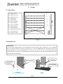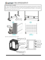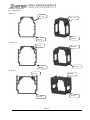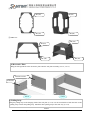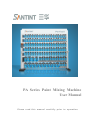
1
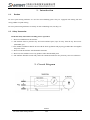
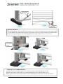
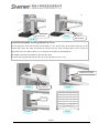
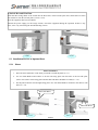
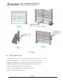
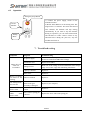
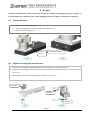
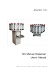
PA Series Paint Mixing Machine
User Manual
P l ea se rea d th i s ma n u a l c a ref u ll y p ri o r to o p era ti o n .
© 2010 All Rights Reserved. Zhengzhou Sanhua Technology & Industry Co., Ltd.
Disclaimer
All parts of the manual are protected by the copyright law. No part of the manual may be reproduced, stored in a
retrieval system, or transmitted, in any form or by any means, electronic, mechanical, photocopying, recording or
otherwise, without the prior written permission of Zhengzhou Sanhua Technology & Industry Co., Ltd. The
company will not be responsible for the technical, editorial errors or omissions of the manual. And will not be
responsible for the damage caused by accident or derivation because of supplying the material or characteristics or
use of the product as well.
The product information of Zhengzhou Sanhua Technology & Industry Co., Ltd. provided by the user’s manual is
for customer’s use only. Nobody can use the information for other use without the prior written permission of
Zhengzhou Sanhua Technology & Industry Co., Ltd.
To keep the interests of ongoing product improvement, Zhengzhou Sanhua Technology & Industry Co., Ltd. will
reserve the rights to alter the product specifications without informing the customers. The company will not
inform the customers if there is alteration of information in the document.
We attempt to assure the rightness and integrity of the contents during compiling the user’s manual of the product,
however we cannot guarantee that there are not any errors or omissions in the user’s manual. If you have any
problems during the process of the product installation, operation and use, please contact Zhengzhou Sanhua
Technology & Industry Co., Ltd.
The users can select the product configuration according to the self’s needs. Meanwhile, the sales team and
training engineers of Zhengzhou Sanhua Technology & Industry Co., Ltd. will assist the users to choose the best
configuration with great effort.
Santint
PA Series Paint Mixing Machine
V2.0
International Quality System Certification
Contents
1.
I n trod u cti on .......................................................................................................................... 1
1.1. Product.................................................................................................................................................. 1
1.2. Safety Instruction................................................................................................................................. 1
2.
Ci rcu i t Di agra m ................................................................................................................... 1
3.
Ap p earan ce an d Tech n i cal Paramet ers ..................................................................... 2
3.1 Appearance............................................................................................................................................ 2
3.2 Technical Parameters of PA Series ..................................................................................................... 2
4.
S etu p Prep arati on ............................................................................................................... 2
5.
S etu p ......................................................................................................................................... 3
5.1
5.2
5.3
5.3.1
5.3.2
5.3.3
6.
Spare Parts ........................................................................................................................................... 3
Setup Process ........................................................................................................................................ 3
Installation Process of Optional Parts.............................................................................................. 10
Platen .................................................................................................................................................. 10
Left/Right Hanging Plate ...................................................................................................................11
Back-storing Shelf and Mica Shelf ................................................................................................... 12
Us age ....................................................................................................................................... 13
6.1
6.2
Check-up Before Usage ..................................................................................................................... 13
Operation ............................................................................................................................................ 14
7.
Trou b l esh ooti n g ................................................................................................................. 14
8.
Rep ai r ..................................................................................................................................... 15
8.1
8.2
8.3
9.
Tension the chain. .............................................................................................................................. 15
Replace the Spring Pin and Jackscrew. ........................................................................................... 15
Replace the Plastic Cone-Gear Assembly ........................................................................................ 16
Mai n ten an ce ........................................................................................................................ 16
9.1
9.2
9.3
Dalily Maintenance ............................................................................................................................ 16
Periodical Maintenance ..................................................................................................................... 16
Maintenance for Long Time No Use................................................................................................. 16
1 0 . Na mep l ate ............................................................................................................................. 17
Santint
PA Series Paint Mixing Machine
V2.0
1. Introduction
1.1.
Product
PA series paint mixing machines are used for auto-refinishing paint. They are equipped with mixing lids and
rotary paddles for paint mixing.
PA series paint mixing machines are mainly for auto-refinishing store; 4S shop; etc.
1.2. Safety Instruction
Read this Safety Instruction carefully prior to operation.
1)Do not let children near the machine.
2)The machine must be placed in dry and well-ventilated space, kept far away from the any heat source
(flammable gas).
3)The machine installation shall be in line with the local regulations and properly grounded. Do not lengthen
the power chord.
4)Do not clean the machine with flammable materials.
5)Do not use this machine to mix any products other than intended paint.
6)The machine should be stored in dry and well-ventilated warehouse away from any corrosive substances.
2. Circuit Diagram
Santint
PA Series Paint Mixing Machine
V2.0
1
3. Appearance and Technical Parameters
3.1 Appearance
3.2
Technical Parameters of PA Series
PA Mixing
Machine
NO. of Cans at
Each Shelf
Mixing
Speed
(RPM)
Dimension
(Standard Configuration)
6 Series
6 large/9 small
72
1360 X 700 X 2117
8 Series
8 large/12 small
72
1720 X 700 X 2117
72
2080 X 700 X 2117
72
2440 X 700 X 2117
10 Series
12 Series
10 large/15
small
12 large/18
small
4. Setup Preparation
Keep this manual at hand for future use.
1) The paint mixers are delivered in sets. It might be packed in several cartons or in one carton.
2) Follow the installation procedures listed in the manual.
3) Open the motor package, take out the tools and spare parts as well as the technical documents such as
the user manual and the packing list. Check the packed goods with the list. If there is any issue, contact
us.
4) Check the power supply voltage frequency to see whether it is in line with the data on the nameplate of
the equipment motor.
5) This manual is general for the PA series. The figures shown and the number of the cans might be
different from your products. The installation procedures and usage methods are the same.
Santint
PA Series Paint Mixing Machine
V2.0
2
5. Setup
5.1 Spare Parts
01---Bottom Cover
02---Large Can Cover
03---Small Can Cover
04---Pulling Strip
05---Bottom Plate
06---Power Assembly
07---Right Mudsill
08---Large Can Shelves
09---Left Side Plate
10---Right Side Plate
11---Switch Box Assembly
12---General Shelves
13---Decorative Plate
5.1.1
5.2 Setup Process
1) Side Plate
Rotate four P395 hanging shafts into the threaded holes of the right side plate (preparation). Use two M8X20
bolts to fix the left side plate on the power assembly (5.2.1). Use two M8X20 bolts to fix the right side plate on
the right mudsill (5.2.2). The finished position is shown in 5.2.3. Notes: The power assembly and the right
mudsill should be located in the predefined position or leaned against the wall. The mixing machine does not
need relocation after installation.
Left Side Plate
Right Side Plate
Hanging Shaft
Power Assembly
Preparation
5.2.1
Santint
PA Series Paint Mixing Machine
V2.0
3
Right Side Plate
Right Mudsill
5.2.2
5.2.3
2) Bottom Shelf Assembly
Put one end of the bottom plate on the power assembly and its other end on the right side plate (5.2.4). Fasten
two M8X20 screws respectively on the two ends of the bottom shelf assembly (5.2.5). Insert the screws on the
left of the bottom shelf assembly into the hole of the bottom plate of the side plate (5.2.6). Repeat for the right
end (5.2.7).
5.2.4
5.2.5
Bottom Shelf
Bottom Plate
Insert into the hole
5.2.6
5.2.7
Santint
PA Series Paint Mixing Machine
V2.0
4
3) General Shelves Assembly
Put 2 sets of backing plate support units onto the bottom shelf (5.2.8) (Reference the Adjustment of Backing
Plate Support Units). Put the general shelves assembly onto the backing plate support units (5.2.9). Use four
M8X20 screws to fasten the shelves onto the holes of the left and right side plate assembly (5.2.10). Install the
other general shelves in the same way (5.2.11).
Support Units
5.2.8
5.2.9
Screw
5.2.10
5.2.11
Adjustment of Backing Plate Support Units:
Backing Plate (80)
4L Can
Support Units
2.5L Can
1L Can
Chamfer
Backing Plate (40)
Santint
PA Series Paint Mixing Machine
V2.0
5
Standard Configuration:
BP = Backing Plate
①4L Can:
BP(80)
BP(80)
BP (40)
BP (40)
② 2.5L Can:
BP (80)
BP (80)
BP (40)
BP (40)
③ 1L Can:
BP (80)
BP (80)
BP (40)
BP (40)
Santint
PA Series Paint Mixing Machine
V2.0
6
④ 5L Can:
BP (80)
BP (80)
BP (80)
BP (80)
⑤ 0.5L Can:
BP (80)
BP (80)
BP (40)
BP (40)
4) Decorative Plate
Hang the left/right hook of the decorative plate onto the side plate assembly (5.2.12, 5.2.13).
Decorative Plate
Side Plate
5.2.12
5.2.13
5) Pulling Strip
Hang the pulling strip on the hanging shaft of the side plate (5.2.14). Use the turn buckle to hook the hole on the
pulling strip. Tension the pulling strip. Install the other pulling strip in the same way (5.2.15).
Santint
PA Series Paint Mixing Machine
V2.0
7
Pulling Strip
5.2.15
5.2.14
Pulling Strip
6) Driving Link Rod
Install the claw-shaped washer into the bottom coupler (5.2.16). Place the driving link rod (with coupler and flat
key) in the middle of the bottom shelves and driving assembly. Connect the coupler with the claw-shaped washers.
Keep the two ends of the flat key level. Fasten the M6X12 bolt on the coupler (5.2.17, 5.2.18, 5.2.19).
Claw-shaped
Washer
5.2.17
5.2.16
5.2.18
5.2.19
7) Bottom Cover and Bottom Plate
Use M6X12 screws to install the bottom cover into the four holes of the left side plate (5.2.20).
Hang the bottom plate on the bottom cover and the hanging shaft of the right side plate (5.2.21).
Rotate the turn buckle of the mixing machine. Tension the pulling strip. Side plates vertical to the ground.
Santint
PA Series Paint Mixing Machine
V2.0
8
Bottom Cover
5.2.21
Bottom Plate
5.2.20
8) Link Rod Assembly and Large/Small Can Cover
Get the supportive units into the link rod assembly (5.2.22). Fasten them on the 5X24 spring pin of the
vertical drive shaft. The other end should be inserted into the shelf assembly shaft (5.2.23). Open the
large/small can covers and use them to cover the link rod assembly by fastening them.
The length of the link rod should be in line with the spans.
Cover the shelf support units and the end caps on the top shelf (5.2.24, 5.2.25).
Link Rod Assembly
5.2.22
5.2.23
Support Unit
Cover
5.2.24
5.2.25
Santint
PA Series Paint Mixing Machine
V2.0
9
9) Switch Box and Pilot Run.
Insert the three fixing shafts of the switch into the three holes of the left side plate. Press them down to fasten
the switch box onto the left side plate (5.2.26, 5.2.27).
Now the equipment has been assembled.
Connect the power supply (see the Usage section). Check the equipment during the operation. If there is any
issue, solve it by referencing the Troubleshooting section.
5.2.26
5.2.27
5.3 Installation Process of Optional Parts
5.3.1 Platen
Platen Installation
1. Place the shelf with holes on the shelf you intend to install the platen (5.3.1).
2. Use two bolts M6X12 and washers to fix the left fixing plate onto the holes of the left side plate
(notice: the surface of the fixing plate and the shelf with holes should be leveled) (5.3.1.2).
3. Put the platen onto the left and right fixing plates. Use four bolts M4X8 to fix them to the shelves with
holes (5.3.1.4).
Shelf with Holes
Shelf with Holes
5.3.1
5.3.2
Santint
PA Series Paint Mixing Machine
V2.0
10
Platen
Screw
Right Fixing Plate
5.3.3
5.3.4
5.3.2 Left/Right Hanging Plate
1. Use the horizontal hook on the right hanging plate to hook the side bracket of the right side plate.
Use the vertical hook on the right hanging plate to hook the square hole of the right side plate. Push
down the hanging plate to make it level with the bottom of the side plate (5.3.5, 5.3.6, 5.3.7).
2. Install the left hanging plate onto the left side plate by the same method (5.3.8).
Square Hole
Side Bracket
Vertical Hook
Right Side Plate
Horizontal Hook
5.3.5
5.3.6
Right Hanging Plate
Right Hanging Plate
Left Hanging Plate
Right Side Plate
5.3.7
PA Series Paint Mixing Machine
Santint
V2.0
5.3.8
11
5.3.3 Back-storing Shelf and Mica Shelf
1. Place the supportive units of the back-storing shelf beside the motor (5.3.9), use two M6X12 screws to
hang the back-storing shelf onto the holes to the left side plate (5.3.10). The surfaces of the back-storing
supportive plates level with the relevant shelves. Install all the back-storing shelves in the same way (The
left/right supportive units with turn buckles shall be leveled with the shelf at the 6th level) (5.3.11).
2. Insert the two bulging ends of the back-storing shelves into the slots of the back-storing supportive plates.
The short one should be hung on the supportive units of the back-storing shelf. (5.3.12).
3. Connect one end of the pulling strip with the back-storing shelf supportive unit of the 3rd level. The other
end should be connected with the turn buckle (5.3.13). Fix the supportive units with the back-storing
shelves via M6X12 screws. Turn the buckle and tension the pulling strip (5.3.14).
4. Connect the mica mount and the mica shelf by M8X50 screws. Do not fasten the screws (5.3.15), fix them
onto the relevant position of the right side plate (5.3.16).
5. Fasten all the screws.
Supportive Unit
5.3.9
5.3.10
Turn
Buckle
Back-storing
Shelf
Supportive Unit
of Storing Shelf
5.3.11
5.3.12
Santint
PA Series Paint Mixing Machine
V2.0
12
Supportive Strip
5.3.13
5.3.14
Mica Shelf
Mount
5.3.16
5.3.15
6. Usage
6.1
Check-up Before Usage
1) Check the local voltage, if it is the same with the nameplate, connect the power supply.
2) The can used should be in line with the equipment, do not use deformed cans.
3) Make sure the mixing lid is fastened prior to installing the cans on the shelf.
4) Make sure the paint is mixed prior to installation on the shelves one by one.
5) Mix the paint thoroughly prior to changing any paints.
6) Check the equipment thoroughly to see if there is any issue.
7) All the fixing parts should be fastened.
Santint
PA Series Paint Mixing Machine
V2.0
13
6.2
Operation
Emergency Stop Button
1) Connect the power supply, switch on the
miniature breaker.
2) Rotate Timer Knob to set the mixing time. The
longest time is 15 minutes. No sooner the enacted
time exhausts, the machine will stop mixing
automatically. If you want to stop the machine
during its operation, you can rotate Timer Knob
anti-clockwise to “OFF”. Notice: if there is any
abnormal noise during the pilot run, stop the
machine and check it.
Circuit
Breaker
Timing
Knob
7. Troubleshooting
Symptoms
Diagnosis
Troubleshooting
No power supply
Check the socket, the power cord, small circuit breaker or
the fuse to ensure Switch Box has a charge.
Switch Box issue
Replace Switch Box
Voltage too low
Make sure if the voltage is located within the local voltage
range ±5%; If not, equip with stabilizing transformer.
Capacity is broken
Replace it
Motor issue
Replace it
Motor is working,
but reducer is not
working.
Reducer is broken
Replace it
One mixing heads
does not mix
Slotted Setscrew in
plastic Cone-gear
Assembly is damaged
Replace it (See “Repair”)
Whole
layer
doesn’t work.
Link Rod Assembly is
broken
Replace it
Partial or the
whole
shelf
doesn’t work.
Sleeve tube or spring pin
is broken.
Replace the sleeve tube or the spring pin.
Motor does not
work or is
overloaded.
Santint
PA Series Paint Mixing Machine
V2.0
14
8. Repair
All repairs & maintenances must be done after stopping the machine and unplugging the power supply. No
repair & maintenance should be done without unplugging the power supply or during mixer operation.
8.1
Tension the chain.
1) Unfasten the motor fixing screw (8.1.1).
2) Rotate the pulling bolt clockwise to tension the chain (8.1.2).
3) Fasten the motor fixing screw.
Clock Wise Rotation
Unfasten
Screws
8.1.1
8.2
8.1.2
Replace the Spring Pin and Jackscrew.
1. Unscrew the fixing bolts by dismantling the driving shaft from the shelf assembly (8.2.1).
2. Hold the broken spring pin with steel column or iron nail. Knock it off with a hammer softly. Install a new
one (8.2.2).
3. Dismantle the broken jackscrew and replace it with a new one (8.2.3).
Main Drive
Jackscrew
Spring Pin
8.2.1
8.2.2
Santint
PA Series Paint Mixing Machine
V2.0
15
8.3
1.
2.
3.
4.
Replace the Plastic Cone-Gear Assembly
Dismantle the shelf to view the shelf assembly (8.3.1).
Dismantle the four fixing bolts of the broken shelf frame and the fixing bolts of the neighboring frame (8.3.2).
Pull upward the shelf assembly to dismantle it from the neighboring sleeve (8.3.2).
Replace it with a new shelf assembly, fasten all the bolts.
Shelf Assembly
8.3.1
8.3.2
9.
Maintenance
In order to keep the machine in optimum condition and reduce accidence, you should perform daily and periodical
maintenance (Note: Be careful when performing maintenance).
9.1 Dalily Maintenance
Clean the machine and the paint leftover on cans and mixing lids (Stop the machine).
9.2 Periodical Maintenance
If the unit has a cyclical reducer, the lubricating grease should be filled after 3 months of usage. It is
recommended to use the molybdenum disulfide or calcium base grease.
If the unit has a gear reducer, the lubricating maintenance is not a necessity.
9.3 Maintenance for extended period of no use.
1)Cut off the power supply.
2)Lubricate all parts of the machine.
3)Cover the machine.
4)Follow “6. Operation” when reusing the machine.
Santint
PA Series Paint Mixing Machine
V2.0
16
10. Nameplate
Santint
PA Series Paint Mixing Machine
V2.0
17
ZHENGZHOU SANHUA TECHNOLOGY & INDUSTRY CO. LTD.
ADD: Xushui Industrial & Trading Park, Zhongyuan West Road,
Zhengzhou City, Henan Province. PR. China. 450042
TEL:0371-67857220
After-Service:0371-67857319
FAX:0371-67857166 WEB:http://www.santint.com
E-mail:[email protected]
Santint
PA Series Paint Mixing Machine
V2.0