1
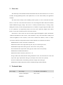
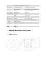
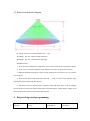
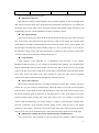
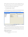
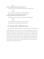
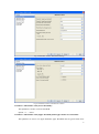
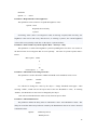
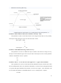
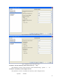
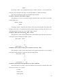
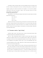
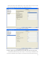
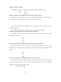
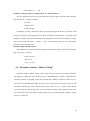
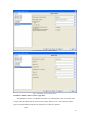
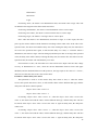
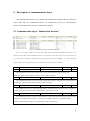
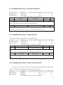
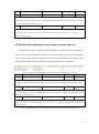
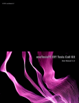
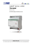
Guangzhou Video-Star Electronics Co.,Ltd. K-BUS Sensor BP User manual-Ver. 1 CSBP-02/00.1 Intelligent Installation Systems http://www.video-star.com.cn Contents 1. Overview ------------------------------------------------------------------------------------------------------ 3 2. Technical data ------------------------------------------------------------------------------------------------ 3 3. Dimension and induction schematic diagram ---------------------------------------------------------- 4 3.1 Dimension drawing --------------------------------------------------------------------------------------------- 4 3.2 Induction schematic diagram ---------------------------------------------------------------------------------- 5 4. 5. Project design and programming ------------------------------------------------------------------------ 5 4.1 Parameter window “General” ---------------------------------------------------------------------------- 7 4.2 Parameter window “Illumination Setting” ------------------------------------------------------------- 8 4.3 Parameter window “Movement Setting” ------------------------------------------------------------- 12 4.4 Parameter window “Logic Setting” ------------------------------------------------------------------- 15 4.5 Parameter window “Master Setting” ------------------------------------------------------------------ 18 Description of communication object ------------------------------------------------------------------- 22 5.1 Communication object “Illumination function” ---------------------------------------------------------- 22 5.2 Communication object “Movement function” ------------------------------------------------------------ 23 5.3 Communication object “Logic function” ------------------------------------------------------------------ 23 5.4 Communication object “Master-Slave function” --------------------------------------------------------- 23 5.5 Disable/enable illumination, movement and logic function -------------------------------------------- 24 2 1. Overview This manual provides detailed technical information about the Sensor BP for users as well as assembly and programming details, and explains how to use the Sensor BP by the application examples. The Sensor BP is mainly used in building control systems; it can be connected with other devices via the bus. The Sensor BP connects to the bus though the EIB connection terminals without additional supply voltage. The sensor is surfacely mounted mostly on ceiling, firstly drilling then fixed by the left and right shrapnel. It is available to assign the physical address and set the parameters by Engineering design tools ETS with VD2/VD3 (higher than edition ETS2v1.3).It is able to install VD3 file if use ETS3 software. Sensor BP is a device that can sense movement signal and brightness signal, and transmit induction information to other devices, such as dimmers, relays. The Sensor BP is mainly used with the brightness of the occasion, or the need to monitor the situation, if there is subject movement, and then it will perform actions. Product functions are summarized as follows: ●Illumination level: 0lux~65535lux, resolution 1lux ●Movement detector area: high sensitivity (4m~5m), low sensitivity(5m~7m) ●illumination output with 3 data types, the values can be sent cyclically ●movement detector output with 3 data types, the values can be sent cyclically ●Illumination with threshold function ●Movement detector sensitivity with level 1~10 ●Logic (AND, OR, XOR) function among illumination value, movement detector value and input value, logic output with 3 data types, the output values can be sent cyclically ●Can be set Master-Slave interworking, the master output with 3 data types ●Illumination enabled, Movement detector enabled and logic enabled function 2. Technical data power supply Bus voltage 21-30V DC, via the EIB bus Current consumption Max. 12mA EIB/KNX 3 Power consumption EIB/KNX Max. 360mW Red LED and push button Assigning the physical address Green LED flashing Indicate the device running normally(OK) Connections EIB/KNX Bus connection terminal Sensing distance Diameter/Radius 7M/3.5M Temperature range Operation –5 °C ... 45 °C Storage – 25 °C ... 55 °C Transport – 25 °C ... 70 °C Ambient condition Humidity <93%,except dewing CE norm In accordance with the EMC guideline and the low voltage guideline Certification EIB/KNX- certified Mounting Mounted in the ceiling, fixed by the left and right shrapnel Dimensions 91×74×76mm Weight 0.05KG Operation/display 3. Dimension and induction schematic diagram 3.1 Dimension drawing 4 3.2 Induction schematic diagram H:Range:2.5m~3m,Recommended value:2.7m W1:Range:4m~5m,Range of high sensitivity W2:Range:5m~7m,Maximum sensing range Installation Notes: 1.Away from air conditioners, refrigerators, stoves where easily lead to temperature change. 2.In the case of a certain temperature, the influence of wind is not great for the Sensor. 3.When the ambient temperature is close to body temperature, the Sensor isn‟t very sensitive or no response. 4.Between the Sensor and person that is detected ,it can‟t be space out by furniture, large potted plants, glass, blinds and other objects. 5.The Sensor can‟t be directly on the windows, doors and where there is direct sunlight, because the hot air out of the window and people movement and the violent change of light, all of them will cause the sensor to send unexpected telegram. 4. Project design and programming Application program Number communication objects Max. number of group address Max. number of associations 5 Sensor BP 21 80 80 Overview of the application program: Illumination function This function is mainly used for lighting, such as outdoor lighting, we turn on the light in the dark, but turn off again in the dawn. If the manual to control these operations are very trouble, but the Sensor can be easily achieve these operations instead of the manual control. The Sensor can automatically sense the current illumination to achieve automatic control. Movement function The Sensor will carry out action when the Sensor detects an object moving. After a period of time, if the Sensor is not detected to any object moving, it will over the action. For example, in the public hallway the light is automatically turned on when the Sensor detect people coming, and then the light is automatically turned off after people leave for a period of time, so as to achieve the maximum energy savings. The movement function of Sensor can also be used to control other occasions, such as the elevator hall, underground garage etc. Logic function Logic function is the integrated use of illumination and movement. It can combine illumination and movement use. For example in controlling home lighting, it is possible that the light is automatically turned on when people enter the room. But we do not need to carry out this action in the day, only in the evening need, and the light is automatically turned off when people leave or the Sensor can‟t detect to any object moving for a time. The entire process of lighting control can be achieved automatically through logic function of Sensor. Master-Slave function Master-Slave function of Sensor is normally used in the occasion that a number of Sensors control one or a class of device simultaneously. When the master receives the special formation from the slaves, it will output the start value and delay for some time. If the master doesn‟t receive the special formation again on delay time, it will output the over value. If the master receives the special formation again on delay time, delay time will be reset. For example, several Sensors control a light simultaneously; one of slave Sensors is sensitive to moving action, then the Slave send out a formation. If the formation that the master receives from the slave is the special formation, it will output a formation to turn on the light. If the delay time has passed, the master doesn‟t receive the special formation again, it will output a formation again to turn off the light. Illumination enabled, Movement enabled and logic enabled function It is convenient for some situation or some cases that need to disable or enable movement, 6 illumination detecting or logic function. When the movement or illumination function of one sensor is disabled, all reaction to the sensor will be ignored about illumination or movement. When the logic function is disabled, the sensor will no longer carry out logic operation either. In the ETS system Sensor BP parameters configuration as follows: 4.1 Parameter window “General” Parameter window “General” can be shown in fig. 4.1. Here can set the type of the sensor, which is as a Standard/Master device or a slave device. Here can also indicate the system delay time after voltage recovery ,the delay time that stabilize the device is fixed for 40s. Fig. 4.1 Parameter window “General” Parameter “System delay time after voltage recovery” This parameter indicates system delay time after bus voltage recovery for the sensor. The delay time is set at 40s in order to stable the device in different conditions, it contains 3 seconds for initialization and 37 seconds for stable of hardware. (During the period of time, it can‟t receive information from other devices, and can‟t also deal with own illumination and movement information, unless stable of hardware.) Parameter “The device type is” The parameter is used to set the type of the sensor. Options: Standard/Slave 7 Master Parameter “Illumination Value 1bit/4bit/1byte object send” The parameter is used to set whether the illumination objects are enabled. Options: Enable Disable If selecting “enable”, the illumination objects normally send values. If selecting “disable”, the illumination objects will be not visible. Parameter “Movement Value 1bit/4bit/1byte object send” The parameter is used to set whether the movement objects are enabled. Options: Enable Disable If selecting “enable”, the movement objects normally send values. If selecting “disable”, the movement objects will be not visible. 4.2 Parameter window “Illumination Setting” Parameter window “Illumination setting” can be shown in fig. 4.2. Here can set illumination function, illumination can be set from 0 to 65535, and upper threshold must greater than lower threshold. The respond mode of the brightness can be also set in the window. Illumination function can make three different types of values sending to the bus (see chart 4.3). When the current illumination is less than lower threshold, the sensor can send the special values of three different types; When the current illumination is between lower threshold and upper threshold, the sensor can also send the special values of three different types; Similarly, when the current illumination is greater than upper threshold, the sensor can also send the special values of three different types. The illumination values sending mode can be set. 8 Fig. 4.2 Parameter window “Illumination Setting” Fig. 4.3 Parameter window “Illumination value1/2” Parameter “Threshold 1 value [Lower threshold]” This parameter is used to set lower threshold. Option:0……65535 Parameter “Threshold 2 value [Upper threshold] ,Must Upper than Lower threshold” This parameter is used to set upper threshold, upper threshold must be greater than lower 9 threshold. Option:0……65535 Parameter “Respond mode of the brightness” This parameter can be set how to respond the brightness value. Option:None Respond, after read only Cyclical If selecting “none”, there is no telegram to send; if selecting “respond, after read only”, the brightness value can be read out by other devices; if selecting “cyclical”, the current brightness value will be sent cyclically on the bus via the object “cyclical send lux”. Parameter “Interval time of cyclical response: Base ×Factor[1…255]” This parameter is visible if the brightness cyclical responding has been select. It is used to set the interval time of two telegrams that are sent cyclically. The time of cyclical response: Base× Factor. Base option:100ms 1s …… 1h Factor option:1……255 Parameter “Threshold can be changed via bus” This parameter is used to determine whether threshold can be modified via bus or not. Options: Disable Enable It is allowed to change the value by the object “ change threshold lower/upper” when selecting “enable”, which can save the input value as the new threshold 1/2 value;If selecting “disable”, the threshold 1/2 value can‟t be changed by the object. Note: The new threshold value will be saved, when bus power down. Parameter “Threshold behavior” The parameter defines the delay status of “threshold 1 value” and “threshold 2 values”. The delay can avoid the unnecessary behavior caused by the illumination value if its value is between 2 threshold values. Options: Without hysteresis With hysteresis 10 Difference between lag and no lag: (without hysteresis, action points 1,2,3,4; with hysteresis, the action point of 1,4) Parameter “Interval time of value cyclic. send: Base × Factor[1…255]” This parameter is used to set the interval time of two telegram values that are sent cyclically. The objects of three data types can be sent. The time: Base× Factor. Base option:100ms 1s …… 1h Factor option:1……255 Parameter “Send illumination Teleg. On bus recovery” This parameter is used to set whether the objects send the values after bus voltage recovery, the objects of three different types can be sent, the values of the objects can be set in the parameter windows “illumination value1/2”. Options: No Yes Parameter “If Lux <= Lower/ If Lower<Lux<Upper/ Lux >= Upper, value send mode” These parameters are used to set the mode that the illumination objects send the values when the current illumination value is less than lower threshold, or is between lower and upper threshold, or is greater than upper threshold. The parameter “If Lower<Lux<Upper,value send mode” will be not visible if the parameter “Threshold behavior” is set to “with hysteresis”. Options: No send 11 Send one time Send cyclically If selecting “no send”, the objects will be not sent any telegram on the bus; if selecting “send one time”, the objects send telegrams for one time; if selecting “send cyclically”, the objects send telegrams cyclically. The interval time between two telegrams is set in the above parameter “Interval time of value cyclic. send: Base × Factor[1…255]”. The objects values are set in the follow parameter “logic 1bit/4bit/1byte” Parameter “logic 1bit/ 4bit/ 1byte” This parameter is used to define the telegram values that the illumination objects send when the current illumination is less than lower threshold and is between lower and upper threshold and is greater than upper threshold. Logic 1bit (0~1) 4bit (0~15) 1byte(0~255) 4.3 Parameter window “Movement Setting” Parameter window “Movement Setting” can be shown in Fig. 4.4. Here can set the movement function, the sensor will active the moving operation when it detects some object moving. Movement function can make three different types of values to be sent the bus (see chart 4.5). When the sensor detects some object moving, it can send the start values of three different types to the bus; if the sensor doesn‟t detect object moving for a period of time, it will send the over values of three different types to the bus. The movement values sending mode can be set. 12 Fig. 4.4 Parameter window “Movement Setting” Fig. 4.5 Parameter window “Movement value” Parameter “Set the sensitivity of movement sensor (1……10)” This parameter is used to set the sensitivity of movement detecting,options:1……10. Parameter “Sensitivity can be changed via bus” This parameter is used to set whether the sensitivity can be changed via bus. Options: Disable 13 Enable If selecting “enable”, the communication object “change sensitivity” will be enabled, the sensitivity can be changed via the object. If selecting “disable”, it will be not changed. Note: The new sensitivity will be saved, when bus power down. Parameter “Function of movement retrigger” This parameter is used to set whether retrigger operation when sensor detects some object moving again or not. Options:Disable Enable If selecting “enable”, when the sensor detects some object moving again on the delay time, the delay time will be reset and the movement operation retrigger. The delay time can be set in following parameter “Delay time of movement:Base ×Factor”. Parameter “Delay time of movement:Base × Factor” This parameter is used to define the delay time, which will be begun when the sensor detects some object moving. The delay time: Base× Factor. Base option:100ms 1s …… 1h Factor option:1……255 Parameter “Interval time of value cyclic. send: Base × Factor[1…255]” This parameter is used to set the interval time of two telegram values that are sent cyclically. The objects of three data types can be sent. The time: Base× Factor. Base option:100ms 1s …… 1h Factor option:1……255 Parameter “If Movement start/ Movement over, value send mode” The two parameters are used to set the mode that the movement objects send the values when the movement start or over. Options: No send Send one time Send cyclically 14 If selecting “no send”, the objects will be not sent any telegram to the bus; if selecting “send one time”, the objects send telegrams for one time; if selecting “send cyclically”, the objects send telegrams cyclically. The interval time between two telegrams is set in the above parameter “Interval time of value cyclic. send: Base × Factor[1…255]”. The objects values are set in the follow parameter “logic 1bit/4bit/1byte” Parameter“logic 1bit/ 4bit/ 1byte” This parameter is used to specify the telegram values that the movement objects send when the movement start and over. Logic 1bit (0~1) 4bit (0~15) 1byte(0~255) When the sensor detects some object moving, the delay time start. If the sensor doesn‟t detect some object moving on delay time, then the delay time over; if the sensor detects some object moving again on delay time, the delay time will be reset or continue to travel time(set by the parameter “Function of movement retrigger”). The delay time is set by the parameter “Delay time of movement: Base×Factor”. 4.4 Parameter window “Logic Setting” Parameter window “Logic” can be shown in Fig. 4.6. Here can set the logic function, which is mainly the integrated use of illumination and movement. There are 3 logic communication objects to decide the result of logic output. The object default value of input 0 for logic can be set via parameter after bus voltage recovery, and can also be modified via the bus. The current illumination determines the value of input 1 that can be set in the illumination value parameter, and the value is sent via the illumination object. The movement determines the value of input 2 that can be set in the movement value parameter, and the value is sent via the movement object. In the case of input 0 enabled, The value of input 1 makes logic operation with the value of input 2 firstly, and then the result after that will makes operation with the value of input 0. According to the final result, logic function can make three different types of values to be sent the bus (see chart 4.7). When the logic result is for “1”, the sensor can send the special values of three different types via the logic objects; when the logic result is for “0”, the sensor can also 15 send the special values of three different types. It will re-operate when receiving a new object values as the final output values. The logic values sending mode can be set Fig. 4.6 Parameter window “Logic Setting” Fig. 4.7 Parameter window “Logic Value” Parameter “input1: logic 1bit of illumination value; input2: logic 1bit of movement value” This parameter indicates the logic value of input 1 is set by 1bit type of illumination value (see chart 4.3), and the logic value of input 2 is set by 1bit type of movement value(see chart 4.5). 16 Parameter “Input 0 of logic is” This parameter is used to set whether enable “input 0”in logic operations or not. Options: Disable Enable Parameter “Object value of input 0 for logic after bus voltage recovery” The parameter is visible when then “enable” is selected in the parameter “input 0 of logic is”. It is used to set object value of input 0 for logic after bus voltage recovery. 0 1 Object value of input 0 can be changed via object “Input 0 of logic”. The object is visible when enable input 0. Note: when the logic operation is disabled, input 0 of value can‟t be changed. Parameter “The logic function type between input1 and input2” The parameter defines the logic function between input 1 and input 2. Three logical operations are available: AND OR XOR Parameter “The logic function type between input 0 and result of input 1/2” The parameter will be seen with “enable” in the parameter “input 0 of logic is”, which defines the logic function between input 0 and result of input 1/2.Three logical operations are available: AND OR XOR Parameter “Logic value cyclical send time: Base × Factor [1…255]” This parameter is used to set the interval time of two telegram values that are sent cyclically. The objects of three data types can be sent. The telegram values can be set in the parameter window “logic value”. The time: Base× Factor. Base option:100ms 1s …… 1h 17 Factor option:1……255 Parameter “If logic result=„1‟/ If logic result= „0‟, value send mode” The two parameters are used to set the mode that the logic objects send the values when the logic result is for “1”and “0”. Options: No send Send one time Send cyclically If selecting “no send”, the objects will be not sent any telegram to the bus; if selecting “send one time”, the objects send telegrams for one time; if selecting “send cyclically”, the objects send telegrams cyclically. The interval time between two telegrams is set in the above parameter “Logic value cyclical send time: Base × Factor [1…255]”. The telegram values are set in the follow parameter “logic 1bit/4bit/1byte” Parameter“logic 1bit/ 4bit/ 1byte” This parameter is used to define the telegram values that the logic objects send when the logic result is for “1”and “0”. Logic 1bit (0~1) 4bit (0~15) 1byte(0~255) 4.5 Parameter window “Master Setting” Parameter window “Master setting” can be shown in fig.4.8. Here set the master parameter, the window is visible only when the device type is standard/master (see chart 4.1). Master-Slave function of Sensor is normally used in the occasion that a number of Sensors control one or a class of device simultaneously. When the master receives the special value from a slave, it will send three different type values, and the special value can be “0” or “1”. If the master doesn‟t receive the special value on delay time, it can also send the values of three different types to the bus. The master values and values sending mode can be set in the parameter window “master value” (see chart 4.9). 18 Fig. 4.8 Parameter window “Master Setting” Fig. 4.9 Parameter window “Master Value” Parameter “Master value as a slave, logic 1bit” This parameter is used to set whether the master‟s own illumination value, movement value or logic value (all values must be 1bit) as a slave input. If they are as a slave input, the master processes the information in the device internal, not via the bus. Options: None 19 Illumination Movement Logic If selecting “none”, the master‟s own illumination value, movement value or logic value will not influence the telegram values that it sends out on bus. If selecting “illumination”, the master‟s own illumination value as a slave input. If selecting “movement”, the master‟s own movement value as a slave input. If selecting “logic”, the master‟s own logic value as a slave input. Note: when the master‟s own illumination, movement or logic as a slave input, after bus power up, the master will do with the formation according to their actual value. If the value is the specified value, the master will send the delay start value. During the delay time, the master does not receive the specified value again, it will send the delay over value, i.e. when the master‟s illumination, movement or logic value has changed, and the input value is no longer the specified value, the delay time will be started, if during the delay time, the master does not still receive the specified value, the master will send the delay over value. If movement as a slave, the movement over value will be slave input value after bus voltage recovery. If illumination as a slave, when the current illumination between lower and upper threshold, and the threshold behavior with hysteresis, the logic input is the value of “<=lower”, otherwise it will be the same as the value of last status. Parameter “Master delay start when” This parameter is used to set the master delay time when to start, i.e. when the master receives the special value from a slave, it will send the values of three different data type, and the delay time will also be started. Options: Object “slave value” receive „0‟ Object “slave value” receive „1‟ If selecting “Object “slave value” receive „0‟”, when the object “slave value” receives the value „0‟, the master will send the values of three different data type, and the delay time will also be started. If the object “slave value” receives the value „0‟ again on delay time, the delay time will be reset. If selecting “Object “slave value” receive „1‟”, when the object “slave value” receives the value „1‟, the master will send the values of three different data type, and the delay time will also be started. If the object “slave value” receives the value „1‟ again on delay time, the delay time 20 will be reset. When the delay time is over, the master will also send the values of three different data type. Note: If the master‟s own value as a salve input, the master will processes the information in the device internal, and do not need receive via the object “slave value”, then trigger that the master send the values of three different data type, and the delay time will also be started. Parameter “Master Delay time:Base ×Factor[1…255]” This parameter is used to define the delay time, which will be begun when the master receives the special value from a slave. The delay time: Base× Factor. Base option:100ms 1s …… 1h Factor option:1……255 Parameter “The master Delay start when receive specified value” This parameter indicates when the master received the specified value, the master delay start. Parameter “If the master receives the value again on delay time, Delay time will be reset” This parameter indicates if the master received the specified value again during delay time, the delay time will be reset. Parameter “When delay start/ When delay over, value send mode” The two parameters are used to set the mode that the master objects send the values when the delay start or over. Options: No send Send one time If selecting “no send”, the objects will be not sent any telegram to the bus; if selecting “send one time”, the objects send telegrams for one time. The telegram values are set in the follow parameter “1bit/4bit/1byte”. Parameter “1bit/ 4bit/ 1byte” This parameter is used to define the telegram values that the master objects send when the delay start and over. 1bit (0~1) 4bit (0~15) 1byte(0~255) 21 5. Description of communication object The communication objects are the medium that communicate with other devices on the bus, which means only the communication object, can communicate on the bus. Communication objects of each function for sensor are summarized as follows: 5.1 Communication object “Illumination function” Fig. 5.1 Communication object “illumination function” Note: “C” in “Flag” column in the below table means that the object has a normal link to the bus; “W” means the object value can be modified via the bus; “R” means the value of the object can be read via the bus; “T” means that a telegram is transmitted when the object value has been modified; “U” means that value response telegrams are interpreted as a write command, the value of the object is updated. No. Function Object name Data type Flags 4 Cyclical send lux value Cyclical send lux value 2byte C,T This communication object will be visible with “cyclical” in the parameter "Respond mode of the brightness”, which is used to send the current Lux value cyclically on the bus. 4 Read lux value Read lux value 2byte C,R,T This communication object will be visible with “respond, after read only” in the parameter "Respond mode of the brightness”, which is used to read the current Lux value via the bus. 5/6 Change threshold lower/upper Chang threshold Lower/Upper 2byte C,W The communication object is visible when the parameter “Threshold can be changed via object” is enabled; it is used to modify the value of threshold 1 and threshold 2. Values range: 0~65535. 8/9/10 Illumination send1bit/4bit/1byte Illumination send 1bit/4bit/1byte 1bit/4bit/1byte C,T The communication objects are used to send illumination values of three different data types when the current brightness is less than the low threshold, or is between lower and upper threshold, or is greater than upper threshold. The illumination values are set in the parameter "logic 1bit/4bit/1byte". Table 5.1 Communication object table “illumination function” 22 5.2 Communication object “Movement function” Fig. 5.2 Communication object “movement function” No. Function Object name Data type Flags 7 Change sensitivity Change sensitivity 1byte C,W This communication object will be seen with “enable” in the parameter "Sensitivity can be changed via bus”, which is used to change the sensitivity of the sensor movement detecting. 11/12/13 Movement send 1bit/4bit/1byte Movement send 1bit/4bit/1byte 1bit/4bit/1byte C,T The communication objects are used to send movement values of three different data types when the movement start or over. The movement values are set in the parameter "logic 1bit/4bit/1byte". Table 5.2 Communication object table” movement function” 5.3 Communication object “Logic function” Communication object “logic function” can be shown in fig.5.3. Fig. 5.3 Communication object “logic function” No. Function Object name Data type Flags 14/15/16 Logic result send 1bit/4bit/1byte Logic result send 1bit/4bit/1byte 1bit/4bit/1byte C,T The communication objects are used to send logic values of three different data types when the logic result is for „0‟ or „1‟. The logic values are set in the parameter "logic 1bit/4bit/1byte". 17 Input 0 of logic Input 0 of logic 1bit C,W The communication object will be seen with “enable” in the parameter “input 0 of logic is”. It is used to modify the value of input 0. Table 5.3 Communication object table “logic function” 5.4 Communication object “Master-Slave function” If the device as a slave, there will be not parameters setting and communication objects; if the device as a master, the communication objects can be shown in fig. 5.4. Fig. 5.4 Communication object “master-slave function” 23 No. Function Object name Data type Flags 0 Slave value Slave value in 1bit C,W The communication is used to receive a value from some slave. If the value is with the special value in the parameter “master delay start when”, the follow objects send the values and the delay time will start. If the value is not the special value, the master is no action. 1/2/3 Master send 1bit/4bit/1byte Master send 1bit/4bit/1byte 1bit/4bit/1byte C,T The communication objects are used to send master values of three different data types when the above object receives the special value from some slave or when the delay time is over. The master values are set in the parameter “1bit/4bit/1byte". Table 5.4 Communication object table “master-slave function” 5.5 Disable/enable illumination, movement and logic function Communication objects of disable/enable illumination, movement and logic functions as shown in fig 5.5. When disable the movement function, any movement detector and operation will be ignored. When disable the illumination function, any illumination to cause change will be ignored. When disable the logic function, the logic operation will be not performed. Fig. 5.5 Communication object “disable/enable illumination, movement and logic function” No. Function Object name Data type Flags 18 Enable Lux Function Enable Lux Function 1Bit C,W The object is used to disable/enable lux function. The lux function is disabled if the object receives a telegram “0”, while it is enabled if the object receives a telegram “1”. The lux function default to enable after bus voltage recovery. 19 Enable Movement Function Enable Movement Function 1Bit C,W The object is used to disable/enable movement function. The movement function is disabled if the object receives a telegram “0”, while it is enabled if the object receives a telegram “1”. The movement function default to enable after bus voltage recovery. 20 Enable Logic Function Enable Logic Function 1Bit C,W The object is used to disable/enable logic function. The logic function is disabled if the object receives a telegram “0”, while it is enabled if the object receives a telegram “1”. The logic function default to enable after bus voltage recovery. Table 5.5 Communication object table “disable/enable illumination, movement and logic function” 24