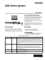
1
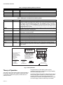
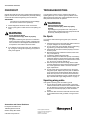
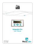
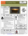
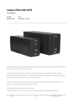
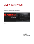
GHE Series Igniters
USER MANUAL
Honeywell High Energy Igniters
The unique high energy circuit makes use of a controlled
capacitor discharge to produce a high energy spark at a pulse
rate of approximately 3 to 5 times per second that ignites
liquid or gaseous fuels more reliably and consistently.
The Honeywell GHE igniter assembly is comprised of two
major parts; a high energy source of ignition and an internal
mix air-gas delivery system.
The third element of the GHE system is a high energy power
pack that delivers 2,000VDC, 12 joules of energy to the end of
the igniter spark tip. The power pack should be installed in a
suitable cabinet.
APPLICATION
FEATURES
Honeywell GHE igniters are non-fouling, inextinguishable,
high-energy electric igniters suitable for most liquid and
gaseous fuels. They are available for both 1-7/8 in. and 2-7/8
in. diameter support tubes in lengths to suit the application.
• High energy output for reliable ignition
• Suitable for most liquid and gaseous fuels
CAUTION
Under no circumstances should this power pack
be used for continuous firing of the igniter.
Table 1. GHE Igniter Ordering Guide.
Base Part Number Length Adder
Description
GHE1-3
IGADD
High energy igniter assembly used with liquid and gaseous fuels, 1-3 MMBTU/hr (about 13 GJ/hr) capacity, 1-7/8 inch OD. Igniter is supplied with 36-inch SS flex gas hose, 36-inch
SS flex air hose, burner mounting tube, high energy probe, igniter tip 12 in. long x 1/2 in
OD. Standard assembly length 2 feet. Use IGADD for each 1-ft assembly length addition.
Order 12-Joule POWERPACK-12-CS and associated cabling with canon plug separately
(IGN-CPC-10). Use IGN-CPC-ADD cable adder for each additional foot in length required
over 10-feet.
GHE2-5
IGADD
High energy igniter assembly used with liquid and gaseous fuels, 2-10 MMBTU/hr (about
2-10 GJ/hr) capacity, 2-7/8 inch OD. Igniter is supplied with 36-inch SS flex gas hose, 36inch SS flex air hose, burner mounting tube, high energy probe, igniter tip 12 in. long x 1/2
in OD. Standard assembly length 2 feet. Use IGADD for each 1-ft assembly length
addition. Order 12-Joule POWERPACK-12-CS and associated cabling with canon plug
separately (IGN-CPC-10). Use IGN-CPC-ADD cable adder for each additional foot in
length required over 10-feet.
QDADD
-
Add quick disconnect/cam and groove coupler on GHE2-5 in place of the standard flange
connection to the burner mounting tube.
IGN-CPC-10
IGN-CPC-ADD Igniter cable 10 ft with canon plug for POWERPACK-12-CS. From power pack to igniter.
To add length, use IGN-CPC-ADD.
69-2682-01
GHE SERIES IGNITERS
Table 1. GHE Igniter Ordering Guide. (Continued)
Base Part Number Length Adder
Description
POWERPACK-12-CS -
12 Joule Power Pack, 120/220Vac/50-60Hz (date code dependent)
NEMA-4X-ADD
NEMA 4X enclosure for igniter powerpack.
-
NEMA-4-ADD
-
NEMA 4 enclosure for igniter powerpack.
NEMA-12-ADD
-
NEMA 12 enclosure for igniter powerpack.
Table 2. GHE Igniter Field Replacement Ordering Guide.
Base Part Number Length Adder
Description
IPASS
HEPADD
GHE igniter probe assembly without burner mounting tube, flange, gas insert or air/gas
flex hoses. Includes high energy probe, igniter tip 12 in. long x 1/2 in OD and junction box
with receptacle. Standard assembly length 2 feet. Use HEPADD for each 1-ft assembly
length addition. Order 12-Joule POWERPACK-12-CS and associated cabling with canon
plug separately (IGN-CPC-10). Use (IGN-CPC-ADD cable adder for each additional foot
in length required over 10-feet.
QDADD
-
Add quick disconnect/cam and groove coupler on GHE2-5 in place of the standard flange
connection to the burner mounting tube.
IGN-CPC-10
IGN-CPC-ADD Igniter cable 10 ft with canon plug for POWERPACK-12-CS. From power pack to igniter.
To add length, use IGN-CPC-ADD.
POWERPACK-12-CS -
12 Joule Power Pack, 120/220Vac/50-60Hz (date code dependent)
NEMA-4X-ADD
-
NEMA 4X enclosure for igniter powerpack.
NEMA-4-ADD
-
NEMA 4 enclosure for igniter powerpack.
NEMA-12-ADD
-
NEMA 12 enclosure for igniter powerpack.
GT-LITE
-
Igniter Spark tip / probe, 12 inch long x 1/2 inch OD.
IGN-CPC-LB
-
Replacement igniter probe junction box with canon plug receptacle for GHE igniters.
HV-HT
HV-HT-FT
Replacement internal GHE igniter cable with contact, 2-feet length standard. Internal
cable from igniter tip to junction box. Use HV-HT-FT cable adder for each additional foot in
length required.
120V POWER SOURCE
L1 - 1
1 - 3 (JUMPER)
2 - 4 (JUMPER)
L2 - 5
G - GROUND
(WIRE SHOWN SOLID)
240V POWER SOURCE
L1 - 1
2 - 3 (JUMPER)
4 - NOT USED
L2 - 5
G - GROUND
(WIRE SHOWN DASHED)
R
YELLOW
BROWN
G
Y
B
BROWN
5
GREEN
4
YELLOW
BLK.
WHITE
5
3
L2
2
BLK.
1
THIS HIGH ENERGY POWER SUPPLY ONLY
FUNCTIONS WITH HIGH ENERGY SPARK TIPS,
NOT HIGH VOLTAGE SPARK PLUGS.
HIGH VOLTAGE
3
NO USER SERVICEABLE PARTS INSIDE. DO
NOT OPEN. RETURN TO FACTORY FOR
REPAIR OR REPLACEMENT.
4
BLK.
BLK.
2
POWER SOURCE:
120V-240V 50HZ-60HZ
5A SUPPLY 600VA, 3 KV
12-16 JOULES
1
CRITICAL: GROUNDED SERVICE MUST
BE SUPPLIED FROM MAIN
ELECTRICAL SUPPLY PANEL. LACK
OF PROPER ELECTRICAL GROUND
WILL CAUSE POWER SUPPLY FAILURE.
L1
DANGER
CSC POWER SUPPLY
MODEL NO. 156-301
TO
SPARK ROD
SPARK GAP SIGHT GLASS
M33220
Fig. 1. Power pack label.
Theory of Operation
The igniter spark tip is self-cleaning. When properly
maintained and operated, it will provide very high availability
and will consistently light off fuels.
The energy output of the igniter is rated in joules, and refers to
the energy of each pulse. The standard 12 joule power pack
supplied with the GHE series igniters produces about 3–5
pulses per second.
69-2682—01
The mixing chamber in the igniter provides a fuel rich zone for
the high energy ignition sparker to provide first stage ignition.
The fuel rich zone is 5-10% of the total fuel input. The
remaining fuel is mixed with air and ignites from the first stage.
The second stage provides the rated output and a stable
2
GHE SERIES IGNITERS
flame even with high velocity surrounding combustion air.
Perforated plates function as a shield and also provide
additional air for stable combustion.
WARNING
Fire or Explosion Hazard.
Can cause severe injury, death or property
damage.
The CSC156-301 power pack (Honeywell Part #
POWERPACK-12-CS) is designated for intermittent operation.
The duty cycle is 1 minute on, with 3 minute off cool down
period.
WARNING
IMPORTANT
Under no circumstances should the POWERPACK12-CS be used for continuous firing of the igniter.
Electrical Shock Hazard.
Can cause severe injury, death or property
damage.
Disconnect power supply before beginning wiring or
making wiring connections to prevent electrical shock
or equipment damage.
INSTALLATION
When Installing This Product…
1.
2.
3.
4.
WARNING
Read these instructions carefully. Failure to follow them
could damage the product or cause a hazardous condition.
Check the ratings given in these instructions to make
sure the integrated furnace control is suitable for your
application.
Installer must be a trained, experienced service technician.
After installation is complete, check out operation as
provided in these instructions.
High Voltage Present
High Voltage is stored in the capacitor and may be
present even after power has been disconnected.
Use a high-voltage grounding probe to ensure the
capacitor is fully discharged.
The GHE Pilot igniter should be mounted to the burner at the
location specified by the burner manufacturer. Ensure
adequate clearance for removal.
The driving energy for the spark probe comes from the power
pack. Since the power pack is delivering high voltage and high
currents, the distance between the power pack and the igniter
tip can be critical. Long cable runs increase the voltage drop
and thus deliver lower power to the igniter tip. To reduce
power loss on the high tension line, cable should be limited to
20 feet or less in length (about 6 meters). If a longer cable
length is required, contact the factory.
The power pack can be mounted in an optional NEMA/IP
enclosure. NEMA 4, 4X and 12 enclosures are available from
the factory.
1/2
(13)
1/4 (6) NPT PLUG IN
3/8 (10) NPT SCANNER PORT
2 FEET – 24 FEET IN 1 FOOT INCREMENTS
2
(51)
1" NPT
COMBUSTION
AIR
INLET
O 1-29/32
(48)
45?
Q 2-1/2
(64)
3/4 (19) NPT
COMBUSTION
GAS INLET
1-51/64
(46)
4-51/64
4-13/32 (112)
IGNITER POWER
CONNECTION
1/2 (13)
6-1/2 (165)
M33221
Fig. 2. Igniter example.
Equipment Storage
water or extreme temperatures, it is advisable to thoroughly
dry the igniter and then troubleshoot the system (see
“Troubleshooting” on page 4), or at least thoroughly check out
the igniter (see “Checkout” on page 4).
For long-term storage, store the igniter in a heated facility to
minimize condensation and corrosion. The normal storage
temperature range is -20 °F to 180 °F (-29 °C to 82° C).
However, if it is suspected that the unit has been exposed to
3
69-2682—01
GHE SERIES IGNITERS
CHECKOUT
TROUBLESHOOTING
Operate the igniter and its control system before attempting a
lightoff. This can often be accomplished by manually shutting
off the fuel valve and then bypassing various interlocks.
If a fuel ignition problem occurs, check that the igniter is
sparking at the tip. If it is, then the ignition problem is most
likely because fuel and air are not being delivered to the tip.
Verify that both fuel and air are present.
IMPORTANT
This should only be attempted with the knowledge
and consent of the burner’s operator(s).
1.
2.
WARNING
Electrical Shock Hazard.
Can cause severe injury, death or property
damage.
High voltages may be present even if the power is
disconnected. Troubleshooting this equipment should
be done by trained personnel only!
Check all physical, electrical, and air connections.
Power up the igniter to make sure that it is sparking correctly.
WARNING
Fire or Explosion Hazard.
Can cause severe injury, death or property
damage.
The igniter is delivering the spark into a combustion
area. Ensure the furnace is properly purged and the
fuel is introduced in the designed controlled manner
as required to meet national and local codes.
3.
If any difficulty occurs at this point, see “Troubleshooting” on page 4. If the igniter is sparking, the system is
ready to test lightoff.
No Spark
If no spark is observed during the igniter cycle, check the
following:
1.
2.
3.
4.
5.
6.
7.
8.
Check supply power to the power pack; make sure there
is proper voltage to the correct terminals.
Turn off power and ground the high tension cable using
high tension ground probes before proceeding.
Check that all wires are connected properly to their termination points.
With the high tension cable disconnected, check continuity to the spark tip.
If necessary, replace the power pack.
Carbon buildup will not affect the spark tip. If necessary,
replace the spark tip. Disconnect the high tension cable.
To remove the tip, hold the tip nut and loosen the socket
nut. To remove, pull the tip straight out.
Remove spark tip and check for a high tension cable
continuity between the power pack end and the spark tip
end. If the high tension cable or connector are damaged, replace them.
Try the igniter with a power pack known to be good. If
the igniter sparks, replace the power pack. A defective
power pack cannot be field repaired. Before removing
make sure the power is off and short each terminal to
ground using a high tension probe, to make sure all voltage is drained. See “High Voltage Present” on page 3.
Sparking along cable
If the igniter is sparking from the cable to ground:
1. Turn off the power. Make a visual check of the igniter
cables and electrical connectors. Ensure that the cables
are not damaged, connectors are seated properly, and
all wires are connected properly to their termination
points.
2. Check the cable connectors and make sure both ends
of the cable braid are well grounded, if using armored
cable.
Automation and Control Solutions
Honeywell International Inc.
1985 Douglas Drive North
Golden Valley, MN 55422
customer.honeywell.com
® U.S. Registered Trademark
© 2011 Honeywell International Inc.
69-2682—01 M.S. 12-11
Printed in United States