1
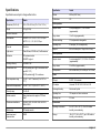
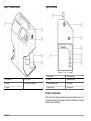
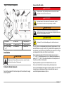
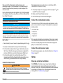
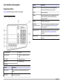
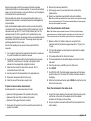
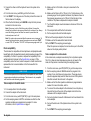
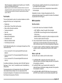
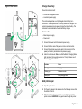
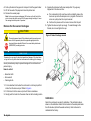
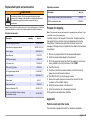
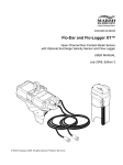
DOC026.53.80184
HIAC PODS GLYCOUNT
10/2013, Edition 3
User Manual
Table of Contents
Specifications ..................................................................................................................................................................................3
General information .....................................................................................................................................................................4
Safety information ..............................................................................................................................................................................4
Use of hazard information ..................................................................................................................................................................4
Precautionary labels ..........................................................................................................................................................................4
Class 1 laser product .........................................................................................................................................................................4
Certification ........................................................................................................................................................................................5
Product overview ...............................................................................................................................................................................5
Product components ..........................................................................................................................................................................6
Installation .........................................................................................................................................................................................7
Connect external pressure .................................................................................................................................................................7
Connect the CO2 bottle ..............................................................................................................................................................7
Connect the shop air source .......................................................................................................................................................8
Connect the communications cables .................................................................................................................................................8
Connect the external power supply ....................................................................................................................................................8
Startup .................................................................................................................................................................................................8
Power up and self-test verification .....................................................................................................................................................8
User interface and navigation ...............................................................................................................................................9
Keypad description ............................................................................................................................................................................9
See the system status menu parameters ........................................................................................................................................10
Set the operation variables ..............................................................................................................................................................10
Operation ..........................................................................................................................................................................................12
Procedure to take a sample .............................................................................................................................................................12
Prepare to take a sample with a bottle .....................................................................................................................................12
Prepare to take an online measurement ...................................................................................................................................13
Flush the instrument in bottle mode ..........................................................................................................................................13
Flush the instrument in the online mode ...................................................................................................................................13
Fluid compatibility .....................................................................................................................................................................14
Take a sample in the bottle mode .............................................................................................................................................14
1
Table of Contents
Take a sample in the online mode ............................................................................................................................................14
Test results ......................................................................................................................................................................................15
Buffer operation ...............................................................................................................................................................................15
See the contents .......................................................................................................................................................................15
Delete or print data ...................................................................................................................................................................15
See the sample data .................................................................................................................................................................16
Maintenance ...................................................................................................................................................................................16
Clean the instrument ........................................................................................................................................................................16
Change the filter ...............................................................................................................................................................................16
Charge the battery ...........................................................................................................................................................................17
Add printer paper .............................................................................................................................................................................17
Remove the flow sensor blockages .................................................................................................................................................18
Calibration ........................................................................................................................................................................................18
Troubleshooting ..........................................................................................................................................................................19
Replacement parts and accessories ...............................................................................................................................21
Prepare for shipping .................................................................................................................................................................21
Appendix ..........................................................................................................................................................................................21
Particle count and other codes ........................................................................................................................................................21
2
Specifications
Specification
Details
Specifications are subject to change without notice.
Altitude
2000 m (6561.7 feet)
Details
Certifications
CE
Dimensions (D x W x H)
18.5 x 33.0 x 40.0 cm (7.3 x 12.5 x 15.7 in.)
Bottle operation
Weight
9.3 kg (20.5 lb)
Sample volume
3 runs (averaged) of 5, 10 or 20 ml/run
(programmable)
Number of channels
8
Purge volume
15 to 30 ml (programmable)
Size channels
ISO-MTD 4, 4.6, 6, 9.8, 14, 21.2, 38, 68 μm
Pressure cartridge
CO2, replaceable, rechargeable
Operating time
60 samples (120 ml sample bottle)
Shop air
620 to 758 kPa (90 to 110 psi; 6.2 to 7.6 bar)
Specification
ACFTD ~1, 2, 5, 10, 25, 50, 100 μm
Flow rate
50 ml/min
Light source
Class 3B laser, 810-852 nm, 50 mW maximum
Calibration
PSL spheres in water
ISO-MTD in glycol
Online operation
Sample volume
3 runs (averaged) of 5, 10, 20, 50 or 100 ml/run
(programmable)
Counting efficiency
JIS B9925:1997
Purge volume
25 to 999 ml (programmable)
Concentration limit
20,000 particles per ml @ 5% coincidence loss
(per ISO 11171)
Fluid pressure
690 to 20684 kPa (100 to 3000 psi; 7 to 207 bar)
30,000 particles/ml @ 10% coincidence
Power
Fluid temperature range
0 to 65 °C at 25 °C ambient (32 to 150 °F at
77 °F)
DC input
24 VDC, 2 A maximum
Measured fluid temperature
0 to 65 °C, ±0.5 °C (32 to 150 °F, ±0.9 °F)
AC adapter
Universal 100–240 VAC, 50–60 Hz, 60 W
Viscosity range
2 to 50 cSt
Rechargable battery
Nickel-metal hydride
Operating time
100 samples or 4 hours continuous
Recharge time
2.5 hours
Wetted materials
Brass, stainless steel, sapphire, PTFE and
®
Aflas
Cleanliness classification
ISO 4406-1991, ISO 4406-1999, NAS 1638,
SAE AS 4059
Data storage
500 sample records
Input/output serial
communication
RS232
Environment
Operating environment
0 to 50 °C (32 to 122 °F), 20 to 85% relative
humidity, non-condensing
Storage
-40 to 70 °C (-40 to 158 °F), up to 98% relative
humidity, non-condensing
English 3
General information
NOTICE
In no event will the manufacturer be liable for direct, indirect, special,
incidental or consequential damages resulting from any defect or
omission in this manual. The manufacturer reserves the right to make
changes in this manual and the products it describes at any time, without
notice or obligation. Revised editions are found on the manufacturer’s
website.
Safety information
NOTICE
The manufacturer is not responsible for any damages due to misapplication or
misuse of this product including, without limitation, direct, incidental and
consequential damages, and disclaims such damages to the full extent permitted
under applicable law. The user is solely responsible to identify critical application
risks and install appropriate mechanisms to protect processes during a possible
equipment malfunction.
Please read this entire manual before unpacking, setting up or operating
this equipment. Pay attention to all danger and caution statements.
Failure to do so could result in serious injury to the operator or damage
to the equipment.
Make sure that the protection provided by this equipment is not impaired.
Do not use or install this equipment in any manner other than that
specified in this manual.
Indicates a situation which, if not avoided, may cause damage to the instrument.
Information that requires special emphasis.
Precautionary labels
Read all labels and tags attached to the instrument. Personal injury or
damage to the instrument could occur if not observed. A symbol, if noted
on the instrument, will be included with a danger or caution statement in
the manual.
This symbol, if noted on the instrument, references the instruction
manual for operation and/or safety information.
Electrical equipment marked with this symbol may not be disposed of
in European public disposal systems after 12 August of 2005. In
conformity with European local and national regulations (EU Directive
2002/96/EC), European electrical equipment users must now return
old or end-of-life equipment to the Producer for disposal at no charge
to the user.
Note: For return for recycling, please contact the equipment producer or supplier
for instructions on how to return end-of-life equipment, producer-supplied
electrical accessories, and all auxiliary items for proper disposal.
This symbol indicates the need for protective eye wear.
Use of hazard information
DANGER
Indicates a potentially or imminently hazardous situation which, if not avoided, will
result in death or serious injury.
WARNING
Indicates a potentially or imminently hazardous situation which, if not avoided,
could result in death or serious injury.
CAUTION
Indicates a potentially hazardous situation that may result in minor or moderate
injury.
4 English
Class 1 laser product
This instrument is classified as a Class 1 laser product. This product
complies with IEC/EN 60825-1:2007 and 21 CFR 1040.10 except for
deviations pursuant to Laser Notice No. 50, dated June 24, 2007.
US FDA Accession number 9912262-006. This product contains a
810-852 nm, 50 mW, class 3B laser that is not user-serviceable.
Certification
Canadian Radio Interference-Causing Equipment Regulation,
IECS-003, Class A:
Supporting test records reside with the manufacturer.
This Class A digital apparatus meets all requirements of the Canadian
Interference-Causing Equipment Regulations.
Cet appareil numérique de classe A répond à toutes les exigences de la
réglementation canadienne sur les équipements provoquant des
interférences.
FCC Part 15, Class "A" Limits
Supporting test records reside with the manufacturer. The device
complies with Part 15 of the FCC Rules. Operation is subject to the
following conditions:
1. The equipment may not cause harmful interference.
2. The equipment must accept any interference received, including
interference that may cause undesired operation.
4. Reposition the receiving antenna for the device receiving the
interference.
5. Try combinations of the above.
Product overview
The Portable Glycol Analysis System (GlyCount) is used to measure,
keep and report glycol contamination data that is important for reliable
filter system operation. The instrument takes an analysis of pressurized
fluids and lubricants in online or bottle sampling modes without
disruption of machine operations.
The instrument is compatible with glycol hydraulic fluids. The instrument
comes with refillable CO2 bottles for use in the field and a shop-air port
fitting for in-house operation. For different views of the instrument, refer
to Figure 1 and Figure 2.
Note: Due to U.S. shipping restrictions, the instrument is shipped with empty CO2
bottles.
Changes or modifications to this equipment not expressly approved by
the party responsible for compliance could void the user's authority to
operate the equipment. This equipment has been tested and found to
comply with the limits for a Class A digital device, pursuant to Part 15 of
the FCC rules. These limits are designed to provide reasonable
protection against harmful interference when the equipment is operated
in a commercial environment. This equipment generates, uses and can
radiate radio frequency energy and, if not installed and used in
accordance with the instruction manual, may cause harmful interference
to radio communications. Operation of this equipment in a residential
area is likely to cause harmful interference, in which case the user will be
required to correct the interference at their expense. The following
techniques can be used to reduce interference problems:
1. Disconnect the equipment from its power source to verify that it is or
is not the source of the interference.
2. If the equipment is connected to the same outlet as the device
experiencing interference, connect the equipment to a different
outlet.
3. Move the equipment away from the device receiving the interference.
English 5
Figure 1 Product overview
Figure 2 Side view
1 Waste bottle
5 Pressure gauge
1 Printer door
4 CO2 bottle
2 Handle
6 Power input port
2 Display
5 Sample bottle adapter
3 Shoulder strap D-ring
7 RS232 port
4 Clean-out port
8 Shop air port
3 Keypad
Product components
Make sure that all components have been received. Refer to Figure 3. If
any items are missing or damaged, contact the manufacturer or a sales
representative immediately.
6 English
Connect the CO2 bottle
Figure 3 Instrument components
DANGER
Multiple hazards. Only qualified personnel must conduct the tasks
described in this section of the document.
DANGER
Explosion hazard. For the safe use of the instrument, obey the
precautions and the instructions as specifically described.
WARNING
Personal injury hazard. Enclosed systems contain high pressure.
Qualified personnel must remove pressure from the system before the
instrument can be installed or removed.
CAUTION
1 Instrument
4 Power cord
7 Printer paper (2x)
2 AC power adapter
5 Sample bottle (10x)
8 Cleaning brush (2x)
3 CO2 bottle, empty
(2x)
6 Allen wrench
9 Software disc
Installation
WARNING
Multiple hazards. Only qualified personnel must conduct the tasks
described in this section of the document.
Connect external pressure
Connect the supplied CO2 bottle or shop air to the instrument to supply
external pressure.
Fire hazard. Do not use flammable agents to clean the instrument.
The CO2 bottle is a compressed gas bottle under high pressure. Do not
alter this bottle in any way. Use only CO2 bottles that are supplied by the
manufacturer. Use the bottle only as directed in this manual. For storage
and disposal of the bottle, refer to the text on the bottle.
Do not expose the pressurized bottle to temperatures in excess of
177 °C (350 °F). Bottles exposed to a fire or heated to temperatures in
excess of 177 °C (350 °F) should be discarded. Let the temperature of
the bottle cool before it is discarded.
Keep the protective cap on the CO2 bottles that are not in use.
Valves must be installed or removed only by trained personnel.
Use only a mild detergent and water to clean the cylinder. Use of caustic
cleaners may corrode pressure fittings or tank walls and cause an
uncontrolled pressure release or rupture.
English 7
Make sure that the bottle adapter is installed properly when
pressurization begins. If the bottle adapter is not installed properly, it
comes off the instrument and personal injury and/or damage to the
instrument occurs.
Due to multiple shipping rules and regulations, the CO2 bottles supplied
in the shipping container are empty. Make sure that the bottles are filled
by a certified CO2 supplier.
NOTICE
Do not remove or cover the label on the bottle.
NOTICE
This bottle must only be filled and transported by properly trained personnel in
accordance with compressed gas bottle filling regulations of the local jurisdiction.
NOTICE
The bottle adapter is a pressure vessel used for sample delivery through the
instrument. It is critical that it is installed in the locked position before sampling.
The bottle adapter must be aligned on the instrument and in the locked position.
Item to collect:
• Clean lubricant (for ease of use and to prevent damage to the O-ring)
1. Examine the threads and the O-ring on the bottle for damage.
2. Turn the bottle clockwise into the CO2 port. As the bottle turns into
the CO2 port, the bottle valve opens and pressure is applied to the
instrument. When this occurs, the bottle becomes difficult to turn.
3. Turn the bottle another ¼ turn until the bottle stops. If CO2 is
released around the bottle threads when this pressurization occurs,
remove the CO2 bottle and examine the O-ring for damage.
Connect the shop air source
WARNING
Personal injury hazard. Enclosed systems contain high pressure.
Qualified personnel must remove pressure from the system before the
instrument can be installed or removed.
8 English
The compressed air source must be clean, dry and between 620 to
758 kPa (90 to 100 psi; 6.2 to 7.6 bar).
1. If the shop air nipple is the wrong type, install a new nipple. A 1/8-inch
male NPT connection is required.
2. Make sure that the port threads are clean.
3. Connect the shop air to the instrument and tighten.
Connect the communications cables
The instrument has an RS232 communications port installed. Use this
port to communicate with a computer for data acquisition, analysis and
remote operation.
•
•
•
•
Baud rate: 9600
Data bits: 8
Parity: None
Stop bits: 2
If the computer or terminal has a 9-pin serial port with a male connector,
use a standard serial cable that has a male end and a female end. The
instrument is already configured as Data Communication Equipment
(DCE). A null-modem cable is not necessary.
Connect the external power supply
If an external power supply is used, obey the instructions in Charge the
battery on page 17.
Startup
Power up and self-test verification
Push POWER and the startup screen shows, then the initialization
screen shows the serial number and firmware revision level of the
instrument. At this point, the instrument examines its internal systems for
any problems. If a problem is found, the instrument shows an error
message. Refer to Troubleshooting on page 19.
User interface and navigation
Keypad description
Figure 4 shows the features included on the keypad.
Feature
Description
CANCEL
Cancels a sample test or cancel a programming
function and maintain the previous selection.
START
Starts a sample test.
Display
Shows the information on the counting process, error
codes, sample test results and the status of the
operating variables.
POWER
Sets the power on and off.
BATTERY
CHARGING STATUS
light
Shows the current mode of operation for the charging
system. For more information, refer to Charge the
battery on page 17.
Alphanumeric keys
Adds letters and numbers into the program. For more
information, refer to Set the operation variables
on page 10.
Navigation keys
Selects operating variables and moves the cursor left
and right.
Figure 4 Keyboard features
1 Function keys
6 POWER
2 LINE FEED
7 BATTERY CHARGING STATUS
light
3 CANCEL
8 Alphanumeric keys
4 START
9 Navigation keys
5 Display
Feature
Description
Function keys
Push the function key to activate an attribute on the
screen.
LINE FEED
Moves the printer paper.
English 9
See the system status menu parameters
To add letters:
Push F3 (SYS) in the main menu to get the system status menu. Table 1
shows various system parameters that the instrument measures. These
system parameters show convenient information and diagnostic
troubleshooting.
a. Push the numeric key that contains the letter to use in
succession.
b. Push once for the number, twice for the first letter, three times for
the second letter, etc. The time between the key pushes tells if
the current character is selected or if the next character is
selected.
Table 1 System parameters
Parameter
Description
Power supply
Shows whether the instrument is connected to the external
power supply or it is operated from the internal battery. When
an external power supply is used, the battery icon shows that
the internal battery is controlled by the external power supply.
When the internal battery is used, the battery icon shows the
remaining relative battery supply voltage capacity. The useful
battery voltage range for the instrument is 11.5 to 13.8 volts.
The amount of battery life that stays below this range is
minimal, so charge the battery before operation is continued.
Internal
temperature
Shows only the temperature inside the instrument enclosure.
This measurement tells if the temperature is too hot or cold to
do a sample test.
Printer status
Shows the different status conditions or errors of the internal
printer. If the printer is good, a condition of NORMAL shows.
An error message shows if a problem exists.
For an explanation of these error codes, refer to Troubleshooting
on page 19.
Set the operation variables
The operation variables are located under the Setup menu. Refer to
Table 2 – Table 6. To set an operation variable:
1. Push F1 (SETUP) to get the Setup menu.
2. Push the numeric number on the keypad that corresponds to the
number on the left side of the variable to program.
3. Push F1 (PRG) and use the navigation keys to select the proper
setting or use the keypad to input numbers, letters or symbols.
10 English
To add symbols:
a. Push the function key that shows the symbol to be used.
b. Push F1 for a space, F2 for a forward slash and F3 for a period.
4. Push F4 to accept the new setting or push CANCEL to return to the
Setup menu and keep the previous selection.
5. To see the test results in a different Standard, Viscosity or
Temperature, set the variables and see or print the test results from
the buffer. Refer to Test results on page 15.
Table 2 Setup menu
Table 2 Setup menu (continued)
Variable
Description
Variable
Description
SAMPLE
LABEL
Shows a second menu, Sample Text menu. Under this menu,
set the following items:
VOL
Volume of fluid that runs 3 times during a sample
(Volume/RUN). The BOTTLE mode sampling is limited (5, 10 or
20 ml per RUN).
FLOW
The flow rate is fixed at 50 mL/min.
PRINT
Enables or disables the printer so that it does not automatically
print at the end of a sample. The SETUP option prints the
current instrument setup (ENBL, DSBL or SETUP).
CONTRAST
Use the navigation keys to control the display contrast.
• SAMPLE LABEL “SAMPLE NAME”—The user-input name for
samples. The sample labels limit is 10 characters. For each
sample label, there is an auto-counter extension that increments
up to 500. This extension is reset to one every time a new
sample label is programmed, re-entered or exceeds a count of
500.
• REMARKS—User-input remarks for any additional sample
labeling, as necessary. These optional remarks become part of
the record of any completed samples. Records retrieved from
the sample buffer can have their remarks reviewed and reedited as necessary. The sample remarks limit is 10 characters
on any of 3 lines. Any existing remarks show on printed sample
reports.
MODE
Sampling method (BOTTLE or ONLINE or FILTER)
If BOTTLE mode is selected or re-entered, a second screen is
shown and it allows the following variable to be set.
• PURGE VOL—Volume of fluid that flows through the
instrument to purge any contamination before samples are
taken (15–30 ml).
If ONLINE mode is selected or re-entered, a second screen is
shown and it allows the following variable to be set.
• NUM SAMPLES—Numbers of samples that run during the
sampling period (1–500).
• HOLD TIME—Time delay from the end of a sample to the start
of the next sample. If set for 00:00, a minimum 5-second hold
time is set (hh:mm).
• PURGE VOL—The volume of fluid that flows through the
hydraulic hose and unit to purge any contamination before
samples are taken. The longer the hydraulic hose, the greater
the purge volume must be (15–999 ml).
STD
Table 3 Screen: PG 2
Variable Description
LANG
Shows the language used in the operation and control of the
instrument (English, French, German, Span and Ital).
TEMP
Shows the temperature units (°C or °F).
PRESS
Shows the pressure units (BAR or PSI).
DISPL
Controls the brightness of the background: light background (Normal)
or dark background (Reversed) (NORM or REV).
BKLT
Controls the back light on the LCD display. If AUTO is selected, the
back light turns off after 5 minutes of inactivity (ON, OFF or AUTO).
BEEP
Controls audio feedback of the beeper when a key is pushed (KEY or
DSBL).
BSAVE
Battery save feature. If enabled, the instrument automatically turns off
after 15 minutes of no activity (Idle state) ((ENBL (Enabled) or DSBL
(Disabled)).
Controls the standard format to show the sample results
(ISO(C), ISO, NAS(C), NAS, NAV(C), NAV, SAE(C), SAE, MIL,
P/10 ml or P/1 ml).
English 11
Table 4 Screen: SIZ
Programmable size menu. When MODE is set to P/1 ml or P/10 ml, the
PG2 menu becomes available for any of the eight size channels to be
programmed. The minimum and maximum size program limit is 4.0 to 68.0 μm.
The size must be programmed in an ascending order from the smallest size on
channel 1 to the largest size on channel 8.
Note: If needed, use F2 (DEFAULT) to reset all sizes to factory default settings.
Table 5 Screen: I/O
Variable Description
UNIT_ID Sets a unique device address that is used in the serial communication
of the instrument MODBUS protocol (01–99).
CNTRL
Set to LOCAL when the instrument is manually operated. Set to
REMOTE when a computer program operates and controls the
instrument sampling. Set to DOWNLOAD when a computer program
retrieves the records from the sample buffer only. The setting of this
variable can also be changed automatically through the serial
MODBUS protocol (LOCAL, REMOTE or DOWNLOAD).
Table 6 Screen: CLK
Variable
Description
TIME
Current time in 24-hour format (Hours/Minutes/Seconds)
DATE
Current date (Month/Day/Year)
Operation
WARNING
CAUTION
Chemical exposure hazard. Dispose of chemicals and wastes in
accordance with local, regional and national regulations.
Procedure to take a sample
Use proper techniques to take a sample. It is important to get a
representative sample of the contamination level of the system under
test. Take the sample from a source with moving fluid.
Note: If the sample is taken from a slow-moving stream, a non-representative
sample can result. Let the system run for at least 30 minutes before a sample is
taken.
Note: The Filter mode is no longer active. Use one of the other modes to take a
sample.
When a series of tests is complete, there is still some sample inside the
instrument. This instrument must be flushed with a fluid that does not
contaminate the next sample. To flush the instrument:
1. Use the same fluid type as intended for the next sample. Do not mix
fluid types. If other fluid types are used, fluid incompatibility causes
sampling errors.
2. If an online operation is used, the instrument is flushed with the fluid
to be tested. For proper flush of the instrument, the flush volume
must be approximately twice that of the internal volume of the
hydraulic hose that connects the instrument to the system to be
tested.
3. Do a maximum flush before a sample is taken to make sure that an
accurate sample measurement. To flush the instrument, refer to
Flush the instrument in bottle mode on page 13 or Flush the
instrument in the online mode on page 13.
Note: An excessive amount of flushes causes prematurely clogged filters.
Chemical exposure hazard. Obey laboratory safety procedures and
wear all of the personal protective equipment appropriate to the
chemicals that are handled. Refer to the current safety data sheets
(MSDS/SDS) for safety protocols.
12 English
Prepare to take a sample with a bottle
Common sources of contamination inadvertently added to fluid samples
come from the bottles, pick-up tube, and airborne particles. Use only
clean sample bottles and keep them covered at all times.
Sample inaccuracies result from excessive air bubbles and water
contamination. Both are counted as particles. To remove the air bubbles,
apply a vacuum to the sample in a vacuum chamber or put the sample in
an ultrasonic bath for several seconds.
Particles settle to the bottom of a sample bottle within minutes, so a
sample should be shaken to re-suspend the particles and degassed to
remove bubbles.
Highly contaminated samples soak the sensor and make the particlecount data invalid. The instrument limit is 20,000 particles per ml at 5%
coincidence loss (per ISO11171) and 30,000 particles per ml at 10%
coincidence loss of fluid for a specific size. If contamination is seen
suspended in a fluid sample, the sample contains concentrations beyond
the saturation limits of the instrument. The average person only sees
particles greater than 40 μm in size.
Use the fluid sampling vacuum pump to take sample fluid from
reservoirs.
1. Cut a length of clean tube that extends from the fluid in the reservoir
to a point accessible from outside the reservoir.
2. Connect a clean sample bottle to the fluid sampling vacuum pump
(VP633001). Install one end of the tube to the pump so that it
extends into the sample bottle and tighten the knob.
3. Install the other end of the tube into the reservoir. Do not
contaminate the end of the tube.
4. Use the pump to fill the sample bottle to the applicable level.
5. Disconnect the sample bottle from the pump.
6. Install the cap until the sample is ready to test.
Prepare to take an online measurement
2. Remove the previously tested fluid.
3. Set the purge volume to two times the internal volume of the
hydraulic hose.
4. Speak to an application specialist before the port installation.
Note: Do not install any additional fluid control devices on the hydraulic sample
hose or the system test port. These devices make bubbles and create particle
traps that cause sample inaccuracies.
Flush the instrument in bottle mode
Note: If the flushed volume exceeds the amount of fluid in the bottle adapter,
pneumatic pressure is flushed through the instrument and out of the drain port.
This creates air pockets in the hydraulic system and leads to sampling errors.
1. Make sure that a CO2 bottle or shop air is connected to the
instrument and that the pressure gauge shows 90 to 110 psi (6.2 to
7.6 bar).
2. Turn the bottle adapter counterclockwise to disconnect the adapter
from the instrument.
3. Fill a sample bottle with the fluid to be flushed.
4. Put the sample bottle into the bottle adapter and connect it to the
instrument.
5. From the main menu, push F4 to go to the flush menu.
6. Push START.
7. Push F1 (SOL ON). The bottle adapter pressurizes and fluid begins
to exit the drain port. The amount of fluid that is flushed is shown on
the display.
8. When the fluid has been flushed, push CANCEL to stop the fluid and
return to the main menu.
Suitable places for an online measurement include:
Flush the instrument in the online mode
• Upstream of the high pressure filter (condition after pump)
• Upstream of the return filter (condition after system)
• Upstream of the bypass filter (tank condition)
1. Connect the online adapter to the instrument. Move the pick-up tube
into the hole in the center of the adapter and turn the adapter
clockwise until the pick-up tube is locked.
®
2. Connect a hydraulic hose with a Minimess test hose thread to the
online adapter.
1. Disconnect the hydraulic hose that connects the instrument to the
system to be tested.
English 13
3. Connect the other end of the hydraulic hose to the system to be
tested.
4. From the main menu, push F4 to go to the flush menu.
5. Push START. The fluid goes out of the drain port and the amount of
fluid is shown on the display.
6. When the fluid is flushed, push CANCEL to stop the flush process
and return to the main menu.
Note: If the power is set to off while the system is flushed, it causes the
internal flow controller to stay open and allows fluid to continue to flow. Always
cancel the flushing process and allow five seconds to pass before the
instrument power is set to off.
Note: The system stays pressurized after the pressure source is removed. To
remove the system pressure, remove the pressure source and push START,
or select "SOL ON” and then “SOL OFF” until the pressure gauge reads 0 psi.
Fluid compatibility
The instrument is compatible with most petroleum and phosphate ester
based fluids within the specified viscosity and temperature ranges. If the
compatibility of a fluid is in question, compare the compatibility to the
wetted material list included in the Specifications on page 3. If the
compatibility cannot be found, submit a request to a local manufacturer
representative for a recommendation on the fluid use within the
instrument.
NOTICE
The internal components of this instrument are not compatible with water. Water
causes instrument malfunction and damage. The instrument is only compatible
with fluids that contain lubricating properties.
Take a sample in the bottle mode
1.
2.
3.
4.
Put a sample fluid in the bottle adapter.
Connect the adapter to the instrument.
From the main menu, push F1 (SETUP) to go to the setup menu.
Set the sampling mode to BOTTLE and make sure that the other
operation variables are programmed as needed. For more
information, refer to Specifications on page 3.
14 English
5. Make sure that a CO2 bottle or shop air is connected to the
instrument.
6. Make sure that there is 90 to 110 psi (6.2 to 7.6 bar) shown on the
pressure gauge. Due to regulation variances, the pressure shown on
the pressure gauge moves up to 120 psi (8.3 bar) during no-flow
conditions. The pressure drops when a sample is started.
7. Turn the bottle adapter counterclockwise to disconnect it from the
instrument.
8. Fill a sample bottle with the fluid to be tested.
9. Put the sample bottle into the bottle adapter.
10. Connect the sample adapter to the instrument.
11. Make sure that the waste bottle holds the fluid.
12. Push START. The sampling process begins.
When this process is complete, the test results are put in the buffer,
shown on the display and/or printed.
Take a sample in the online mode
In the online mode, a sample moves directly from a hydraulic system.
The CO2 or shop air external pressure sources are not used in this
mode, but they remain connected during the sampling process.
1. From the main menu, push F1 (SETUP) to go to the setup menu.
2. Set the sampling mode to ONLINE and set the program to the
number of runs, hold time and purge volume. The purge volume
should be approximately twice the internal volume of the hydraulic
tube that connects the instrument to the system.
3. Make sure that the other operation variables are programmed as
needed. For more information, refer to .
4. To connect the online adapter to the instrument, move the pick-up
tube into the hole in the center of the adapter and turn the tube
clockwise until the adapter is locked.
5. Connect a hydraulic hose with a Minimess®1 test hose thread to the
online adapter.
6. Connect the other end of the hydraulic hose to the system to be
tested.
7. Push START. The sampling process begins.
When this process is complete, the test results are put in the buffer,
shown on the display and/or printed.
Note: If the power is set to off while the instrument is flushed, it causes the
internal flow controller to remain open and allows fluid to move. Always cancel
the flushing process and allow five seconds to pass before the instrument
power is set to off.
• If the instrument is colder than the fluid, there is a temperature drop of
the fluid while the fluid is sampled.
• If the instrument is hotter, there is a temperature increase while the
fluid is sampled.
Test results
Interpretation of results—Compare the reported results to the
corresponding target ranges for the system that is tested. Fluid treatment
or replacement can then be given.
The count data shows the number of counts per individual run and the
average of the three runs. A test report shows:
Buffer operation
•
•
•
•
•
•
•
•
•
•
Sample type
Serial number of the unit that took the sample
Date and time the sample was taken
Volume per sample run
Flow rate
Measured viscosity
Measured fluid temperature
Concentration units
Measured cleanliness format
Count data per micron size
For ISO Standard reporting, the run volume gives the lowest level of the
contamination code.
• For a run volume of 5 ml, the lowest reported ISO code level is
03/03/03.
• For a run volume of 10 ml, the lowest reported ISO code level is
02/02/02.
• For a run volume of 20 ml, the lowest reported ISO code level is
01/01/01.
For additional information on this subject, refer to ISO 4406 “Hydraulic
fluid power – Fluids – Code,” to calculate the level of contamination by
solid particles.
The temperature shown is the temperature at the end of the hydraulic
circuit (inside the flow controller). It is not a measurement of the
incoming fluid temperature. The hydraulic circuit has thermal masses
that influence the temperature of the fluid.
See the contents
1. Use the buffer menu to see the contents of the buffer:
• LAST SAMPLE—shows the results of the last sample.
• LIST BUFFER—shows the eight most recent sample names for
further review.
• SEARCH BUFFER—searches for a particular sample name. Enter
the entire or partial name of the sample.
2. Once a sample selection has been made, push the corresponding
function keys to see the next sample or the previous sample. The
buffer contents are shown in the currently programmed configuration.
3. To show the results in a different configuration, change the operation
variables to another configuration and look at the buffer contents
again.
Delete or print data
Use the buffer menu to delete or print the buffer contents.
1. Push F2 (DEL BUF) to delete the entire buffer contents. The
instrument shows a confirmation message and asks for the operation
to be accepted or cancelled.
2. Push F3 (PRT BUF) to print the entire buffer contents. The
instrument shows a confirmation message and asks for the operation
to be accepted or cancelled.
3. Push F1 (DEL SMP) or F2 (PRT SMP) while in the average count
(AVG CNT) menu to delete or print an individual sample test result.
English 15
When a sample selection is shown, the average count menu is
available.
See the sample data
When a sample selection is made, the instrument shows the sample
statistics for that particular sample. Push the average count (AVG CNT)
function key to see the remainder of the sample data.
Maintenance
DANGER
Multiple hazards. Only qualified personnel must conduct the tasks
described in this section of the document.
WARNING
Personal injury hazard. Never remove covers from the instrument. This
is a laser-based instrument and the user risks injury if exposed to the
laser.
Clean the instrument
CAUTION
Fire hazard. Do not use flammable agents to clean the instrument.
NOTICE
Make sure not to bend the pick-up tube or scratch the lower end where the seal
connection is made. Damage causes leakage or misalignment with the online
adapter.
1. Clean the instrument with a cleaning brush and a clean glycol base
solution.
2. Flush the instrument.
16 English
Change the filter
To remove the filter, refer to Figure 5.
Figure 5 Filter removal
Charge the battery
Power the instrument with:
• an internal rechargeable battery
• an external power supply
The instrument operates on a fully charged internal battery for a
minimum of 100 samples before the battery needs to be charged. The
external power supply is also used to charge the internal battery. The
instrument can be used while the internal battery charges.
Items to collect:
• External power supply
• Power cord
1. Connect the power cord to the external power supply.
2. Connect the other end of the power cord to an electrical outlet.
3. Connect the external power supply jack to the instrument at the
power port location (located below the pressure gauge).
4. Listen for a click sound. Make sure that the Battery Charging Status
light (located on the keypad) is turned on. This light shows one of
three charging status modes:
Indicator
Status
Steady green
Charging
Flashing green
Maintenance mode
Steady red
Battery charging failure
Add printer paper
1. Open the printer door.
2. Put the printer paper in the instrument so that the paper comes from
the bottom of the roll.
3. While the instrument power is set to on, insert the paper into the
printer and push LINE FEED. The paper feeds through the printer.
English 17
4. Fold up the slack in the paper roll and push it into the paper holder.
5. Lift the free end of the paper and close the printer door.
6. Remove the excess paper.
Note: In the case of paper misalignment, lift the lever on the left side of the
printer to raise the printer carriage. Pull the paper straight and align it. Lower
the carriage before the printer is operated.
Remove the flow sensor blockages
4. Operate the instrument with clean sample fluid. To purge any
trapped air in the clean-out line:
a. Put an absorbent cloth over the wrench and slightly loosen the
clean-out cap while the sample run is in progress. Fluid and air
come out quickly when the cap is loosened.
b. Continue the process until no more air comes from the port.
5. Tighten the clean-out port cap snugly. To avoid damage to the
threads, do not over tighten the cap.
CAUTION
Figure 6 Sensor blockage removal
Chemical exposure hazard. Obey laboratory safety procedures and
wear all of the personal protective equipment appropriate to the
chemicals that are handled. Refer to the current safety data sheets
(MSDS/SDS) for safety protocols.
NOTICE
Excessive force can result in brush and possible cell damage. If the brush does
not go into the cell, pull the brush out and examine the cleaning tip for damage.
Use all precautionary steps to prevent damage to the instrument and
personal injury.
Items to collect:
• Absorbent cloth
• Allen wrench
• Cleaning brush
1. Put an absorbent cloth under the instrument to catch any liquid that
drains from the clean-out port. Refer to Figure 6.
2. Put the brush into the clean-out port until there is resistance.
3. Gently push the brush into the sensor flow cell with a twisting motion.
Calibration
Return the instrument annually for calibration. The calibration date is
shown on the calibration sticker that is located on the serial plate inside
the left side door (behind the waste container). Each instrument is
calibrated at the factory.
18 English
Troubleshooting
Table 7 Critical errors (continued)
For help with potential problems, refer to Table 7 and Table 8.
If the program malfunctions and the instrument needs to be reset to the
default settings, push and hold F4 while the power is cycled.
Error
Flow regulation
failure
Note: This erases all buffer contents and all of the operation variables to their
factory settings. A default message and the firmware part number are shown as the
instrument initializes its systems again.
Table 7 Critical errors
Error
Flow controller
failure
Possible cause
Solution
The unit is unable to find
the HOME switch on the
flow controller during
system initialization or at
the end of a sample test.
Start the instrument again.
There is a flow controller
malfunction.
Contact technical support.
There is trapped air in the
internal hydraulic tubing.
(PODS only)
Remove the air from the internal
hydraulic tubing including the
clean-out port with a clean fluid.
The instrument was not
purged before a change in
the viscosity of the sample
fluid occurred. (PODS
only)
Clean the system with a new
fluid.
Low flow rate,
possible high
viscosity
Possible cause
Solution
The external pressure was
decreased during the
sample test.
Make sure that the external air
source is stable and set near
100 psi. Make sure that there
are no leaks on the sample cup
O-ring.
The instrument was not
purged before a change in
The viscosity of the
sample fluid occurred.
Purge the instrument.
The amount of sample
fluid is not sufficient.
Add more sample fluid.
There was an attempt to
flush the system.
(GlyCount only)
Flush the instrument. Make sure
that sample fluid stays in the
flow path.
External pressure was
decreased during sample
test.
Make sure that the external air
source is stable and set near
100 psi. Make sure that there
are no leaks on the sample cup
O-ring.
The instrument was not
purged before a change in
the viscosity of the sample
fluid.
Purge the instrument.
The sample fluid viscosity
is too high. (PODS only)
Decrease the flow rate or dilute
the sample with a suitable clean,
filtered and miscible fluid that will
decrease the sampling viscosity
to within the range of the counter
(10–424 cSt).
The pick-up tube cap was
not removed.
Remove the cap.
English 19
Table 7 Critical errors (continued)
Error
Possible cause
Solution
Hydraulic
pressure for
online sampling
is not sufficient
The hydraulic pressure
source is not sufficient.
High pressure
found
An internal hydraulic
Contact technical support.
regulator failure occurred
or the adjustment setting is
out of tolerance.
Low pressure
Pressure
dropped to a
level that is not
sufficient
20 English
Make sure that the fluid pressure
is more than 40 psi for all of the
sample period. Make sure that
there are no leaks on the online
adapter O-ring.
The external pressure
source is not sufficient.
Make sure that the external air
source is stable and set near
100 psi. Decrease the flow rate,
especially with high viscosity
fluids. Make sure that there are
no leaks on the sample cup Oring.
The pick-up tube cap is
installed.
Remove the pick-up tube cap.
The external pressure was
decreased during the
sample test.
Make sure that the external air
source is stable and set near
100 psi. Decrease the flow rate,
especially with high viscosity
fluids. Make sure that there are
no leaks on the sample cup Oring.
The sample fluid viscosity
is too high. (PODS only)
Decrease the flow rate or dilute
the sample with a suitable clean,
filtered and miscible fluid that will
decrease the sampling viscosity
to within the range of the counter
(10–424 cSt).
There is an internal
hydraulic regulator failure
or adjustment setting that
is out of tolerance.
Contact technical support.
Table 8 Non-critical errors
Error
SNSR FLOW CELL
ERROR
Possible cause
Solution
There is a blockage in the
sensor cell within the view
area and the detector does
not see the laser light.
Do the cell cleaning
procedure as
described in Remove
the flow sensor
blockages on page 18.
The amount of sample fluid
is not sufficient.
Add more sample fluid.
The sensor is out of
calibration. This results in a
low signal.
Return the unit to the
factory for calibration
or repair.
The sample is contaminated
with water or high particle
contamination.
Remove the water or
try another sample. If
the sample is highly
contaminated, dilute
the sample.
The laser or sensor
electronics failed. (GlyCount
only)
Return the unit to the
factory for calibration
or repair.
The unit could have
been put in a high
temperature location.
Decrease the ambient or
fluid temperature conditions.
Attempts to charge
battery in a higher than
normal ambient
temperature condition.
Batteries get hot near
their end-of-charge
cycle. If ambient
conditions are too hot,
then a battery overtemperature condition
can result and the red
indicator illuminates.
Put the unit in a cool area
until it cools off. If it fails
again, replace the battery.
The battery is faulty.
Replace the battery.
Replacement parts and accessories
Optional accessories
WARNING
Description
Personal injury hazard. Use of non-approved parts may cause
personal injury, damage to the instrument or equipment malfunction.
The replacement parts in this section are approved by the
manufacturer.
Control software (software utility for data collection)
RS232 serial interface cable
Item no.
2087044
EP096010
Note: Product and Article numbers may vary for some selling regions. Contact the
appropriate distributor or refer to the company website for contact information.
Prepare for shipping
Standard accessories
Note: The instrument must be sent back with a decontamination certificate. To get
a certificate, contact the manufacturer.
Description
Quantity
Item no.
Reusable shipping container
1
SA-000197-01
Foam insert for shipping container
1
MP000172-01,-02
Online adapter
1
SA000008-01
Shoulder strap
1
VP753400
AC/DC power supply
1
VP624002
U.S. power cord
1
VP6235001
DOT rated CO2 bottles
1
VP760000
100 ml glass sample bottles
1
570-396-9217
Sensor brushes
2
SA000066-01
Printer paper
1
460 511
High pressure hose
1
VP350000
Ultrasonic Benchtop PC-3
1
690-500-1172
Filter kit (contains filter element, a spring
and stainless washer)
1
540-400-0025
If residual oil stays in the flow path of the counter, the optical switches
that operate the flow controller may be contaminated with oil during
transportation. Potential issues are a Flow Controller Failure error
message or the keypad may not operate. Do the steps that follow before
transportation.
1. Remove any sample bottles from the sample bottle adapter.
2. Attach the sample bottle adapter to the instrument.
3. Do a flush procedure without any fluid in the adapter. From the main
menu, push F4 to go to the Flush menu. Push START.
4. Push F1 (CO2 ON).
5. Flush the air until the flow meter switches on and the fluid in the
system moves into the waste container.
6. Push F2 (CO2 OFF) to stop the purge process.
7. Remove the waste container and remove the contents from the
container. Let the container drip dry.
8. Attach the waste container to the instrument.
9. Attach the protective cap to the sample inlet probe.
10. Complete the decontamination certificate.
Appendix
Particle count and other codes
The instrument is equipped to handle four cleanliness standards:
English 21
• ISO 4406:1999 for NIST/ISO 11171 (μm(c)), internally named ISO(C)
• ISO 4406:1999 for ACFTD/ISO 4402 sizes (μm), internally named
ISOACF
• NAS 1638:1992
• SAE AS4059
The cleanliness standards correlate to four internal standard settings
(Table 9 – Table 12). Select the applicable standard during setup. The
selected standard is printed and kept in memory. At the time of printing,
no cleanliness standard except ISO 4406:1999 specifies a specific
calibration method. Usually users work with ACFTD-calibrations; since
ACFTD is no longer considered valid calibration material, particle
counter manufacturers must change to ISO-MTD calibrations. The other
standards also have to use the ISO-MTD sizes if the cleanliness codes
remain the same.
Table 9 ISO 4406: 1987 (E)
Number of particles per milliliters (counts/mL)
Scale number
Table 9 ISO 4406: 1987 (E) (continued)
Number of particles per milliliters (counts/mL)
Scale number
More than
Up to and includes
640
1300
17
320
640
16
160
320
15
80
160
14
40
80
13
20
40
12
10
20
11
5
10
10
2.5
5
9
More than
Up to and includes
1.3
2.5
8
2,500,000
—
> 28
0.64
1.3
7
1,300,000
2,500,000
28
0.32
0.64
6
640,000
1,300,000
27
0.16
0.32
5
320,000
640,000
26
0.08
0.16
4
160,000
320,000
25
0.04
0.08
3
80,000
160,000
24
0.02
0.04
2
40,000
80,000
23
0.01
0.02
1
20,000
40,000
22
0
0.01
<1
10,000
20,000
21
5000
10,000
20
2500
5000
19
1300
2500
18
22 English
Table 10 NAS 1638 Contamination Classification System
Class
Table 12 SAE AS4059 cleanliness levels by particle count
Maximum particles/100 mL in specified size range (µm)
Maximum contamination limits (particles/100 mL)
5–15
15–25
25–50
50–100
> 100
> 5 µm
> 15 µm
> 25 µm
> 50 µm
> 100 µm
125
22
4
1
0
Size
range
> 1 µm
00
1
0
6-Sep
44
8
2
0
> 4 µm(c)
> 6 µm(c)
1
500
89
16
3
1
Size
range
>
14 µm(c)
>
21 µm(c)
>
38 µm(c)
>
70 µm(c)
2
1000
178
32
6
1
A
B
C
D
E
F
3
2000
356
63
11
2
4
4000
712
126
22
4
5
8000
1425
253
45
8
6
16,000
2850
506
90
16
7
32,000
5700
1012
180
32
8
64,000
11,400
2025
360
64
9
128,000
22,800
4050
720
128
10
256,000
45,600
8100
1440
256
11
512,000
91,200
16,200
2880
512
12
1,024,000
182,400
32,400
5760
1024
2
Size
code
Table 11 Equivalent APC sizes that relate to calibration method
Code and size
Particle sizes
ISO 11171 Size - µm(c)
>4
>6
> 14
> 21
> 38
> 70
ISO 4402 Size - µm
>1
>5
> 15
> 25
> 50
> 100
Class
000
195
76
14
3
1
0
Class
00
390
152
27
5
1
0
Class
0
780
304
54
10
2
0
Class
1
1560
609
109
20
4
1
Class
2
3120
1220
217
39
7
1
Class
3
6250
2430
432
76
13
2
Class
4
12,500
4860
864
152
26
4
Class
5
25,000
9730
1730
306
53
8
Class
6
50,000
19,500
3460
612
106
16
Class
7
100,000
38,900
6920
1220
212
32
Class
8
200,000
77,900
13,900
2450
424
64
English 23
Table 12 SAE AS4059 cleanliness levels by particle count
(continued)
Maximum contamination limits (particles/100 mL)
Class
9
400,000
156,000
27,700
4900
848
128
Class
10
800,000
311,000
55,400
9800
1700
256
Class
11
1,600,000
623,000
111,000
19,600
3390
512
Class
12
3,200,000
1,250,000
222,000
39,200
6780
1020
1
2
Optical microscope, based on longest dimension as measured per ARP598 or
APC Calibrated per ISO 4402:1991.
APC Calibrated per ISO 11171 or Electron Microscope, based on projected
area equivalent diameter.
24 English
Beckman Coulter, Inc.
250 S. Kraemer Blvd.
Brea, CA 92821, U.S.A.
www.particle.com
製造販売元: ベックマン•コールター株式会社
東京都江東区有明三丁目 5 番 7 号
TOC 有明ウエストタワー
©
Beckman Coulter do Brasil Com e Imp de Prod de Lab Ltda
Estr dos Romeiros, 220 - Galpao G3 - Km 38.5
06501-001 - Sao Paulo - SP – Brasil
CNPJ: 42.160.812/0001-44
贝克曼库尔特有限公司,美国加利福尼亚州,
Brea 市,S. Kraemer 大街 250 号,邮编:92821
电话:(001) 714-993-5321
Beckman Coulter, Inc., 2011, 2013. All rights reserved. Printed in U.S.A.