1
Field Automation Systems
GRIDLINK CONFIGURATION SOFTWARE
for the GridBoss™ System
User Manual
Form A6074
September 1999
Applies to Software Version 1.0
Part Number D301131X012
GRIDLINK User Manual
Revision Tracking Sheet
September 1999
This manual may be revised periodically to incorporate new or updated information. The revision date
of each page is indicated at the bottom of the page opposite the page number. A major change in the
content of the manual also changes the date that appears on the front cover. Listed below is the revision
date of each page.
Page
Revision
All
9/99
Notice: The GridBoss System discussed in this manual was developed with the assistance of the
Gas Research Institute (GRI). The GRIDLINK software and firmware contained in the GB600-Series
Controllers is copyrighted by Fisher Controls International, with portions copyrighted by GRI.
© Fisher Controls International, Inc. 1999. All rights reserved.
Printed in the U.S.A.
While this information is presented in good faith and believed to be accurate, Fisher Controls does not guarantee satisfactory results from
reliance upon such information. Nothing contained herein is to be construed as a warranty or guarantee, express or implied, regarding the
performance, merchantability, fitness or any other matter with respect to the products, nor as a recommendation to use any product or
process in conflict with any patent. Fisher Controls reserves the right, without notice, to alter or improve the designs or specifications of the
products described herein.
ii
Rev 9/99
GRIDLINK User Manual
Table of Contents
(For a more detailed listing, see the Section Contents toward the front of each section.)
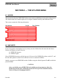
SECTION 1 — GETTING STARTED...................................................................... 1-1
1.1 User Manual Overview................................................................................................................ 1-1
1.2 Section 1 – Getting Started Contents ........................................................................................ ... 1-3
1.3 Additional Information ...................................................................................................... .......... 1-4
1.4 Product Overview........................................................................................................................ 1-4
1.5 User Interface.............................................................................................................................. 1-7
1.6 Software Installation....................................................................................................... ............1-15
1.7 Starting the GRIDLINK Software ..............................................................................................1-27
1.8 Logging On ................................................................................................................................1-28
1.9 Connecting the Computer to the GridBoss..................................................................................1-30
1.10 Configuration Overview .............................................................................................................1-31
SECTION 2 — THE FILE MENU ............................................................................ 2-1
2.1 Scope .......................................................................................................................................... 2-1
2.2 File Menu Overview.................................................................................................................... 2-2
2.3 Direct Connect ............................................................................................................................ 2-3
2.4 GridBoss Directory...................................................................................................................... 2-4
2.5 New…........................................................................................................................................2-11
2.6 Open….......................................................................................................................................2-12
2.7 Collect GridBoss Data ................................................................................................................2-14
2.8 Download… ...............................................................................................................................2-20
2.9 Update Firmware........................................................................................................................2-23
2.10 Update Hardware............................................................................................................ ............2-25
2.11 Convert…...................................................................................................................................2-27
2.12 Print Configuration........................................................................................................ .............2-29
2.13 GRIDLINK Security ..................................................................................................................2-30
2.14 Macros… ...................................................................................................................................2-30
2.15 Exit Alt+X .................................................................................................................................2-30
Rev 9/99
iii
GRIDLINK User Manual
Table of Contents (Continued)
SECTION 3 – THE GRID MENU ............................................................................. 3-1
3.1
3.2
3.3
3.4
3.5
Comm with LPP.......................................................................................................................... 3-2
Regulator Control........................................................................................................... ............. 3-5
Holiday Dates.............................................................................................................................3-15
Comm with DRs.........................................................................................................................3-16
Low Pressure Control.................................................................................................................3-21
SECTION 4 — THE I/O MENU................................................................................ 4-1
4.1
4.2
4.3
4.4
4.5
4.6
4.7
Scope .......................................................................................................................................... 4-1
AI – Analog Input Configuration................................................................................................. 4-2
AO – Analog Output ..................................................................................................................4-11
DI – Discrete Input Configuration ..............................................................................................4-15
DO – Discrete Output Configuration .......................................................................................... 4-20
PI – Pulse Input Configuration ...................................................................................................4-25
Input and Output Point Numbers ................................................................................................4-32
SECTION 5 — THE DATA MENU .......................................................................... 5-1
5.1
5.2
5.3
5.4
5.5
5.6
Scope .......................................................................................................................................... 5-1
FST ............................................................................................................................................. 5-2
Soft Points................................................................................................................. .................. 5-6
Radio Power Control ................................................................................................................... 5-7
Opcode Setup .............................................................................................................................5-11
User List Setup...........................................................................................................................5-13
SECTION 6 — THE DISPLAY MENU .................................................................... 6-1
6.1 Scope .......................................................................................................................................... 6-1
6.2 Custom Displays ......................................................................................................................... 6-1
6.3 Monitor ......................................................................................................................................6-14
SECTION 7 — THE HISTORY MENU ................................................................... 7-1
7.1 Scope .......................................................................................................................................... 7-1
7.2 History Setup .............................................................................................................................. 7-1
7.3 Min/Max History......................................................................................................................... 7-7
iv
Rev 9/99
GRIDLINK User Manual
Table of Contents (Continued)
7.4
7.5
7.6
7.7
7.8
Minute History ............................................................................................................................ 7-9
15-Minute...................................................................................................................................7-10
Day History................................................................................................................................7-11
Events History............................................................................................................................7-13
Alarms History...........................................................................................................................7-15
SECTION 8 — THE UTILITIES MENU ................................................................. 8-1
8.1
8.2
8.3
8.4
8.5
Scope .......................................................................................................................................... 8-1
Security ....................................................................................................................................... 8-1
Macros ........................................................................................................................................ 8-5
GridBoss Memory ....................................................................................................................... 8-8
Calibration Values....................................................................................................................... 8-9
SECTION 9 — THE SYSTEM MENU ..................................................................... 9-1
9.1
9.2
9.3
9.4
9.5
9.6
9.7
Scope .......................................................................................................................................... 9-1
Clock........................................................................................................................................... 9-2
Information ................................................................................................................................. 9-3
Flags ........................................................................................................................................... 9-7
Comm Ports ...............................................................................................................................9-10
Configuring Report-by-Exception ..............................................................................................9-16
Communications Overview ........................................................................................................9-20
SECTION 10 — THE HELP MENU....................................................................... 10-1
10.1 Scope .........................................................................................................................................10-1
10.2 Getting Started ............................................................................................................ ...............10-2
10.3 Keys................................................................................................................................................10-3
10.4 Help Contents.............................................................................................................................10-4
10.5 About .........................................................................................................................................10-5
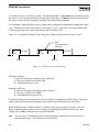
APPENDIX A — TIMED DURATION OUTPUT ...................................................A-1
A.1 Introduction.................................................................................................................................A-1
A.2 Enabling The TDO Function ................................................................................................... ....A-2
Rev 08/99
v
GRIDLINK User Manual
Table of Contents (Continued)
GLOSSARY OF TERMS .......................................................................................... G-1
TOPICAL INDEX .......................................................................................................I-1
vi
Rev 9/99
GRIDLINK User Manual
SECTION 1 — GETTING STARTED
1.1 USER MANUAL OVERVIEW
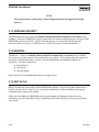
1.1.1 Scope
This manual describes how to use the GRIDLINK™ Configuration Software to configure and monitor
the GB600-Series Controllers of a GridBoss™ Pressure Control and Management System, such as the
GB601 District Regulator (DR) Controller, and the GB602 Low Pressure Point (LPP) Controller. The
GridBoss System controls the Setpoint at the District Regulator Controller through an actuator, such as a
Kixcel™, I/P, or servo valve. The Setpoint is “predicted” by the historical profile of the District
Regulator outlet pressure versus the time-of-day and temperature. The LPP Controller monitors the
average pressure for the minute at a low-pressure point downstream from the District Regulator. The
average pressure for the minute and change in Setpoint for the regulator is relayed back to the DR
Controller when the average pressure for the minute is out of range.
The GRIDLINK software runs on a personal computer (such as a laptop or notebook style) in a MSDOS® operating system (version 5.0 or higher) or in a DOS window. This manual covers configuration,
calibration, monitoring, database archiving, custom displays, and embedded utilities of the GRIDLINK
software.
1.1.2 Organization
This manual is organized according to the menu structure of the GRIDLINK software. A section is
dedicated to each item on the menu bar. The manual is organized into the following major sections:
♦ Table of Contents
♦ Section 1 Getting Started
♦ Section 2 The File Menu
♦ Section 3 The Grid Menu
♦ Section 4 The I/O Menu
♦ Section 5 The Data Menu
♦ Section 6 The Display Menu
♦ Section 7 The History Menu
♦ Section 8 The Utilities Menu
♦ Section 9 The System Menu
♦ Section 10 The Help Menu
♦ Appendix A Timed Duration Output
♦ Glossary of Terms
♦ Topical Index
Rev 9/99
1-1
GRIDLINK User Manual
Table of Contents Lists each section and information contained in that section of the document.
Section 1 Getting Started describes this manual and mentions related manuals. This section also
provides a summary of the GRIDLINK software, installation, hardware overview, basic software
functions, user interface, and logging on to the GRIDLINK software.
Section 2 The File Menu provides information concerning options located under the File menu before
and after logging on to GRIDLINK, including: Direct Connect, GridBoss Directory, New, Open,
Collect GridBoss Data, Download, Update Firmware, Update Hardware, Convert, Print
Configuration, GRIDLINK Security, Macros, and Exit option.
Section 3 The Grid Menu describes the options located under the Grid menu, including: Comm with
LPP, Regulator Control, Holiday Dates, Comm with DRs, and Low Pressure Control.
Section 4 The I/O Menu provides information detailing options located under the I/O menu,
including: AI, AO, DI, DO, and PI.
Section 5 The Data Menu provides information detailing features located in the Data menu, including:
FST, Softpoints, Radio Control, Opcode Setup, and User List Setup.
Section 6 The Display Menu provides information detailing features located in the Display menu,
including: Custom Displays and Monitor options.
Section 7 The History Menu provides information detailing features located in the History menu,
including: History Setup, Min/Max History, Minute History, Hourly History, Day History, Events
History, and Alarms History.
Section 8 The Utilities Menu provides information detailing features located in the Utilities menu,
including: Security, Macros, GridBoss Memory, and Calibration Values.
Section 9 The System Menu provides information detailing features located in the System menu,
including: Clock, Information, Flags, Comm Ports, and configuring RBX Alarming.
Section 10 The Help Menu provides information detailing features located in the Help menu,
including: Getting Started, Keys, Help Contents, and About.
Appendix A Timed Duration Output provides information detailing how to accurately define, set up,
and use the various types of Timed Duration Outputs (TDOs).
Glossary of Terms Defines terms used in Fisher Control’s documentation.
Topical Index Lists alphabetically the items contained in this manual, including the section and page
number.
NOTE
In most cases, the GB602 LPP and GB601 DR controllers (either of
which may be referred to as a GridBoss) are identical in operation.
The descriptions and procedures in all sections apply to both
controllers, except where otherwise noted.
1-2
Rev 9/99
GRIDLINK User Manual
1.2 SECTION 1 – GETTING STARTED CONTENTS
This section contains the following information:
Information
User Manual Overview
Scope
Organization
User Manual Overview
Additional Information
Product
GRIDLINK Configuration Software
GridBoss System Controllers
User Interface
Interface Overview
Menu Bar and Menus
Keyboard and Pointing Devices
Using the Keyboard
Using the Mouse
Function Screens
Dialog Boxes
Help System
Software Installation
Computer Requirements
Software Disk
Software Installation Procedure Using DOS
Software Installation Procedure Using Windows 3.1x
Copying a Disk Using Windows 95, Windows 98 or Windows NT
Upgrade Procedure
Editing the GRIDLINK.PIF in Windows 3.1x
Editing the GRIDLINK.PIF in Windows 95, Windows 98, or Windows NT
Using Windows 95, Windows 98, or Windows NT
Starting the GRIDLINK Software
Logging On
Connecting the Computer to the GridBoss
Configuration Overview
Configuration
Duplicating a Configuration
Communications Overview
GRIDLINK Screen Colors
Adjusting Screen Colors for Monochrome Displays
Rev 9/99
Section Page Number
1.1
1-1
1.1.1
1-1
1.1.2
1-1
1.1
1-1
1.3
1-4
1.4
1-4
1.4.1
1-4
1.4.2
1-5
1.5
1-7
1.5.1
1-7
1.5.2
1-8
1.5.3
1-8
1.5.3.1
1-9
1.5.3.2 1-11
1.5.4
1-12
1.5.5
1-13
1.5.6
1-14
1.6
1-15
1.6.1
1-15
1.6.2
1-15
1.6.3
1-18
1.6.4
1-20
1.6.5
1-21
1.6.6
1-22
1.6.7
1-22
1.6.8
1-23
1.6.9
1-25
1.7
1-27
1.8
1-28
1.9
1-30
1.10
1-31
1.10.1 1-31
1.10.2 1-32
1.10.3 1-32
1.10.4 1-33
1.10.4.1 1-35
1-3
GRIDLINK User Manual
1.3 ADDITIONAL INFORMATION
The physical aspects of the GridBoss units are contained in their respective instruction manuals.
The following manuals include information not found in this manual:
& GridBoss Instruction Manual (Form A6075) – Part Number D301132X012
&
GridManager User Manual (Form A6083) – Part Number D301134X012
&
Function Sequence Table (FST) User Manual (Form A4625) – Part Number D301058X012
&
ROC/FloBoss Accessories Instruction Manual (Form A4637) – Part Number D301061X012
&
ROC Protocol User Manual (Form A4199) – Part Number D301053X12
&
Type 662 Kixcel Remote Control Pilot Drive Actuator – Part Number D102273X012
1.4 PRODUCT OVERVIEW
To better understand the information contained in this manual, this section provides a brief overview of
the operation of the equipment.
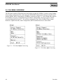
1.4.1 GRIDLINK Configuration Software
The GRIDLINK Configuration Software provides the capability to monitor, configure, and calibrate the
GridBoss Gas Pressure Control system units. The software runs on an IBM-compatible personal
computer (PC) using DOS 5.0 or higher. GRIDLINK can also run as a DOS application with
Microsoft® Windows® 3.1, Windows 95®, Windows 98®, or Windows NT®. The software is supplied on
a 3.5-inch floppy disk.
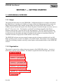
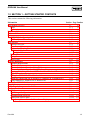
Some of the many functions provided are (see Figure 1-2 on page 1-13 for a complete list of functions):
♦ Configuring I/O points (including Sensor Module inputs), Proportional, Integral, and
Derivative (PID) feedback control loop calculations, and the history database.
♦ Configuring communications setup between the GridBoss 601 District Regulator Controller, the
GridBoss 602 Low Pressure Point Controller, and the Host computer.
♦ Retrieving historical, event, and alarm logged data.
The GRIDLINK software is designed for ease of use. Pull-down menus simplify accessing the functions
provided by the software, and dialog boxes help to direct selections and data entry. Actions can be
performed with the keyboard or a pointing device such as a mouse. Refer to Section 1.5 for a
description of the user interface.
Help screens are accessed either from the Help menu or in a context-sensitive fashion from within the
menus and screens. This feature makes it easy to access on-line information for any GRIDLINK topic.
1-4
Rev 9/99
GRIDLINK User Manual
You can build custom displays for the GridBoss units that combine both graphic and dynamic data
elements. Using GRIDLINK, the displays can monitor the operation of a GridBoss unit either locally or
remotely.
GRIDLINK lets you record custom keystroke sequences called macros, which can “play back” dozens
of keystrokes at a time.
The software also provides multiple levels of security for controlling access to GRIDLINK functions, as
well as the GridBoss databases. Making changes to passwords or to the access level for personnel is
accomplished through the Security menu, which is available only to an authorized person.
1.4.2 GridBoss System Controllers
The GridBoss System uses GB600-Series Controllers, which are pressure measurement computers that
automate the delivery of natural gas at an optimized and adequate pressure for natural gas distribution
systems. These controllers also perform PID loop control, data archival, and remote communications.
The GridBoss System uses two types of controller units: the GB601District Regulator (DR) and the
GB602 Low Pressure Point (LPP) Controller. The DR controller is automated with an actuator such as
the Fisher Type 662 Kixcel. An I/P or servo valve may be used in place of the Kixcel. The GB601
provides functions required for measuring the inlet and outlet pressure of the District Regulator, and the
GB602 measures the line pressure at the Low Pressure Point.
NOTE
An I/P or servo valve may be used in place of the Kixcel. For ease of readability,
“Kixcel” is used throughout this manual to represent all three devices.
The GridBoss System builds load profiles based on ambient temperature and time-of-day, which are
then used to determine the “predicted” Setpoint of the District Regulator. The GridBoss System
provides on-site functionality and supports remote monitoring, pressure measurement, data archival,
communications, and control. The GridBoss System design also allows you to configure specific
applications including those requiring calculations, logic, and sequencing control by using Function
Sequence Tables (FSTs).
The primary function of the GridBoss system is to control a Setpoint for a District Regulator, which
allows the District Regulator to automate the delivering of natural gas at an optimized and adequate
pressure. By using history load profiles originating from the Low Pressure Point data and using the load
profiles at the District Regulator, the GridBoss system predicts system requirements to improve system
integrity and reduce the average system pressure. The LPP GridBoss 602 measures the average line
pressure at the Low Pressure Point downstream from the District Regulator. The average line pressure
at the Low Pressure Point and the required change in Setpoint for the regulator is relayed back to the
District Regulator GridBoss 601 when the LPP pressure goes out of range.
Rev 9/99
1-5
GRIDLINK User Manual
The GridBoss controller has a weather-tight enclosure with a window for a Liquid Crystal Display
(LCD) display, which is further protected by a weather shield cover. This display consists of a 2-line by
16-character alphanumeric display to monitor information stored by the GridBoss units.
The enclosure contains a processor circuit board with built-in input/output (I/O), including mounting
provisions for batteries, a radio, power converter, and an I/O card. The built-in I/O consists of a direct
4-wire Resistance Temperature Detector (RTD) interface, and a discrete output. Additionally, the
District Regulator includes two discrete inputs, two pulse counters, two user configurable pulse or
discrete inputs, two discrete outputs, two analog inputs, and one analog output. An optional intrusion
switch uses one of the discrete inputs.
The GridBoss system can be operated peer-to-peer between the Low Pressure Point and the District
Regulator or as part of a communications system, which includes a Host. Monitored values are
processed and stored for access by personnel in the field using either the LCD display of the GridBoss or
a notebook personal computer (PC) containing the GRIDLINK Configuration Software. Supervisors
and managers at central or field offices can remotely monitor the GridBoss through a Host computer.
The GridBoss units use internal software (called firmware) for gathering input data, converting raw
input data into calculated values, storing values, and providing control signals. Two diagnostic inputs
monitor input power, battery voltage, and enclosure/battery temperature.
Two basic types of memory are used in the GridBoss units: Read-Only Memory (ROM) and Random
Access Memory (RAM). The ROM is programmable (called flash memory). A portion of the ROM
holds the firmware, which is programmed by the factory to contain the operating system and various
application programs. Another portion of programmable ROM stores certain configuration and default
values. The RAM, which is backed up by its own power source, stores history data and additional
configuration data. The GRIDLINK software can access both programmable ROM and the RAM.
Further information is provided in the GB600-Series Instruction Manual (Form A6075).
1-6
Rev 9/99
GRIDLINK User Manual
1.5 USER INTERFACE
You interact with the GRIDLINK software using various displays on the computer monitor and the
computer keyboard and/or pointing device.
The major components of the GRIDLINK user interface are:
♦ Menu bar and menus (affected by the security system)
♦ Function screens
♦ Dialog boxes
♦ Keyboard and pointing devices
♦ Help system, including the Status Line and message boxes
The previous user interface components are presented in Sections 1.4. Section 1.5.1 is an overview of
the user interface.
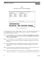
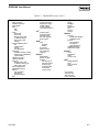
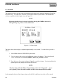
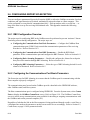
1.5.1 Interface Overview
The GRIDLINK software employs a character-based graphical user interface with a standard Windows
menu structure. After logging on to GRIDLINK, you see the available functions displayed in a menu
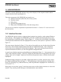
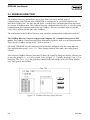
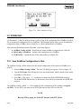
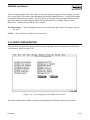
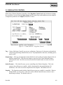
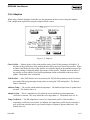
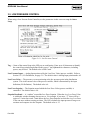
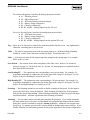
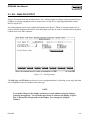
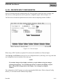
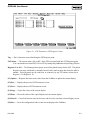
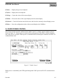
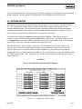
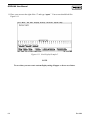
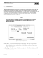
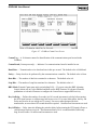
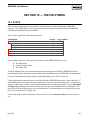
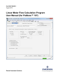
bar with pull-down / drop-down menus. Refer to Figure 1-1. A Status Line at the bottom of the display
contains pertinent information about the highlighted item such as a menu option or a parameter. Refer to
Figure 1-1.
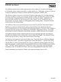
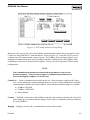
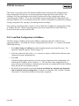
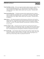
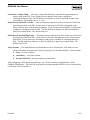
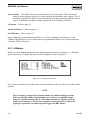
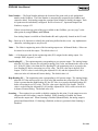
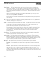
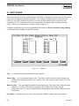
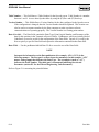
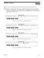
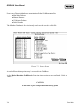
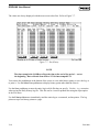
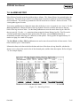
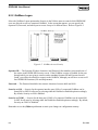
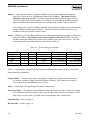
The menu structure displayed in Figure 1-2 lists choices from which you can select the desired function.
Some items, when selected, display another menu that lists additional functions. Once a function is
selected, the screen or dialog box for that function displays. This screen or dialog box provides the
requested information and allows you enter the applicable configuration data.
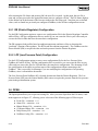
A typical screen displays parameters and pushbuttons as displayed in Figure 1-1. Some parameters have
values, while others have options. Values are contained in data fields next to the parameter name; many
of these values can be changed. Options are listed below the parameter name, with the selected option
highlighted.
Pushbuttons display dialog boxes for further configuration details or perform a desired action, such as
the Adaptive pushbutton shown in Figure 1-1. The pushbuttons are activated either by clicking with a
mouse or by pressing a key (either the Enter key when the pushbutton is highlighted or a function key —
see Section 1.5.3).
Dialog boxes are areas that “pop up” inside the current screen to allow further selections or values to be
entered. They can also provide messages or information that is more detailed.
Rev 9/99
1-7
GRIDLINK User Manual
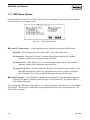
1.5.2 Menu Bar and Menus
The menu bar is the first thing that appears on the screen after successfully logging on. Refer to Figure
1-1. The initial menu bar includes only the File and Help menus. When you connect to a GridBoss or
open a configuration file, the complete menu bar appears. Note that your security level may limit the
menus available to you from the menu bar. Refer to Section 8 for information concerning security
levels.
Menu Bar
Menu
Parameter Name
Data Field
Pushbutton
Status Line
Figure 1-1. Sample GRIDLINK Display
From the menu bar, you can use either the keyboard or the mouse to activate a menu and then to select a
function in that menu.
1.5.3 Keyboard and Pointing Devices
There are two methods for “telling” the GRIDLINK software what to do: the keyboard method and the
pointing device method. The pointing device can be a mouse, a trackball, or other device. Throughout
this manual, the term “mouse” refers to any kind of pointing device you may have.
NOTE
A DOS or Windows mouse driver must be present in your system to use a mouse.
1-8
Rev 9/99
GRIDLINK User Manual
A mouse or trackball is usually easier to use than the keyboard for getting around in the menus and
screens. However, the keyboard is still required to enter text and numerical data. If you only have a
keyboard, you can perform all the operations of the mouse method, but it may not be as fast as using a
mouse, and you need to learn which keys are required for each operation.
1.5.3.1 Using the Keyboard
If you are using the keyboard and the menu bar does not have one of its items (such as File) highlighted,
use the Alt key or the F10 key to activate the menu bar. Use the Left Arrow and Right Arrow keys
to highlight the menu bar item you want (note the help Status Line at the bottom of the screen provides a
brief description of the menu), and then press Enter.
With a menu displayed, you can highlight the desired item by using the Down Arrow and Up Arrow
keys. With the desired item highlighted, press the Enter key to activate the function. Instead of using
the cursor keys and pressing Enter, you can type the white letter of the menu item (such as “A” for
About).
If the menu item is followed by an ellipse (for example, Monitor...), a submenu appears. You can then
select an item from the submenu using the same methods as for the menu.
To leave a menu or submenu, press the Esc key. You can then select another menu. You can also access
another menu simply by using the Left Arrow and Right Arrow key.
The cursor movement keys are the four arrow keys, which are designated as follows:
♦ Up Arrow (↑)
♦ Down Arrow (↓)
♦ Right Arrow (→)
♦ Left Arrow (←)
The text scrolling keys are the Page Up and Page Down keys.
To use the keyboard in configuration screens and dialog boxes, press the Tab key to move in a
predetermined sequence from one parameter field or pushbutton to the next. The field or pushbutton
becomes highlighted to show you which one is selected. Note that fields unavailable for changes are
automatically skipped; they are not highlighted.
When you Tab to the last field or pushbutton in the screen or dialog box, pressing the Tab key again
jumps back to the first field or pushbutton. To go back to a previous field or pushbutton, press the Shift
and Tab keys together.
In an option field, the currently selected option (marked with an asterisk between the parentheses) is
highlighted. To select one of the other options, use the Up Arrow and Down Arrow keys to highlight
the desired option, and then press Enter. The new selection is then marked with an asterisk (*).
Rev 9/99
1-9
GRIDLINK User Manual
In a field that requires a text or numerical entry, type the required characters or numbers from the
keyboard. Use the Backspace or Delete keys to erase unwanted characters. In a text field, you can use
the Right Arrow and Left Arrow keys to move the cursor one character at a time and the Home and End
keys to place the cursor at the beginning and end of the field, respectively.
The following keys or key combinations permit you to perform certain operations pertaining to
GRIDLINK.
Alt+X — While holding down the Alt key, press the “X” key to exit or quit the GRIDLINK software.
Esc — In general, this key cancels the current activity. If a screen is active, this key closes the screen
and returns you to the last-used place in the menu structure. If a dialog box is active, this key
closes the box and returns you to the screen or other place from which the dialog box originated.
If a menu is active, this key closes the last-opened menu, taking you up one level in the menu
structure. If the menu bar is active, this key de-selects all menu options so that none are
highlighted; you then need to use the Alt key or click with the mouse to reactivate the menu bar.
Alt or F10 — When nothing is highlighted on the menu bar, press the Alt or F10 key to reactivate the
bar by highlighting “File.” If you are in a screen, pressing the Alt or F10 key activates the menu
bar for making a menu selection, which effectively cancels any actions being performed on the
screen. To return to the screen from the menu bar, use the Esc key.
F9 — When a menu item or a screen item is highlighted, press the F9 key to display the Help window.
Any available information about the item displays. You can use the Index pushbutton in the
Help window to get a list of help topics. When you are done with the Help window, use the
Cancel pushbutton or the Esc key.
F1 through F8 — In most configuration screens, some of these keys are identified as pushbuttons at the
bottom of the screen. When the pushbutton is present, it works as follows:
F1 Update – Revert to the last saved data of the screen or refresh the display with the latest data.
F2 Prev – Page to the previous point of this type. For example, if the screen for Analog Input
point number A2 is currently displayed, pressing F2(Prev) causes the screen for point
number A1 to display.
F3 Next – Page to the next point of this type. For example, if the screen for Analog Input point
number A1 is currently displayed, pressing F3(Next) displays the screen for point number
A2.
F4 Copy – Copy the configuration data shown in the current screen to a memory buffer. This
copy of the data can then (F5)Paste to another point of the same type to save time in
configuring similar points.
1-10
Rev 9/99
GRIDLINK User Manual
F5 Paste – Paste the configuration data saved in the copy buffer using (F4)Copy to the currently
displayed screen. This overwrites the data on the screen with the data copied from the
similar point. After using F5(Paste), you can make further changes (such as to the Tag).
Remember to (F8)Save the data to the GridBoss or to a disk file.
F6 Cancel – Quit the screen without saving any changes that may have been made.
F8 Save – Save changes either to configuration memory in the GridBoss (on-line configuration)
or to a disk file (off-line configuration).
1.5.3.2 Using the Mouse
When using a mouse to access the menus, you can activate any item on the menu bar by clicking on the
item. Likewise, you can activate any item in a menu by clicking on it. Keep in mind that where the
keyboard method highlights an item and then activates it, clicking with the mouse highlights and
activates the selected item in one step. If you want, you can press the mouse button and drag the mouse
cursor through other menu items or off the menus entirely. Whatever is highlighted (if anything) when
you release the mouse button becomes active.
NOTE
A DOS or Windows mouse driver must be present in your system to use a mouse.
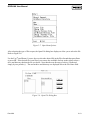
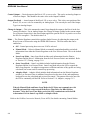
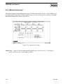
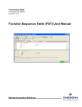
Note that in this manual the menus are arranged in a hierarchy to guide you through GRIDLINK. Figure
1-2 on page 1-13 shows the overall menu structure (called a “menu tree”) for GRIDLINK. The names
in the menu tree are listed as they appear in the software.
NOTE
Not all menu items are active or appear as options. Certain functions are
restricted depending on the type of GridBoss unit and other hardware you
are using. Menu items that are not active appear in gray and cannot be
accessed. Other menu items specific to a function do not appear at all.
To use the mouse in the screens and dialog boxes, click (press and release) on the field you want to
change. For option fields, clicking on an option selects it, marking it with an asterisk (*). For text and
number entry fields that can be edited, click on the field to highlight it. Use the keyboard to enter the
required characters.
Note that you can move most dialog boxes by dragging them with the mouse. To drag a dialog box,
place the pointer on the top border of the box, press and hold the left mouse button (the border turns
white), then move the mouse. When the box is where you want it, release the button.
Rev 9/99
1-11
GRIDLINK User Manual
To use the mouse to activate a pushbutton, just click on the pushbutton. To highlight a pushbutton
without activating it (such as for viewing the pushbutton’s Status Line information), click the mouse
button over the pushbutton (which highlights), drag the mouse off the pushbutton, and then release the
mouse button.
To use the mouse in list boxes, click on an item in a list to highlight it. Then, after highlighting an item,
you can select it with a mouse by double-clicking (clicking twice in rapid succession) on it.
1.5.4 Function Screens
Function screens serve two purposes: to provide information and allow the setting of configuration
parameters. Some function screens are strictly for providing information; however, most serve both
purposes.
Function screens (also called “screens”) appear when a menu function is selected. Screens typically
have a title (such as Regulator Control) and a thin-line border. With the exception of the menu bar and
the Status Line, a function screen fills the whole display. A screen typically has the following
components:
♦ Parameter with a value field
♦ Parameter with an option field
♦ Pushbutton (standard or function key)
1-12
Rev 9/99
GRIDLINK User Manual
File
Grid
Direct Connect
GridBoss Directory
New…
DR Configuration
LPP Configuration
Open..
Event File
Alarm File
Minute History File
15-Minute History File
Daily History File
GridBoss Config. File
2
Collect GridBoss Data...
All
TOD Profiles3
History
Events/Alarms
2
Download...
GridBoss Config. to Disk
Disk Config. to GridBoss
3
TOD Profiles
2
Update Firmware
Update Hardware2
Convert...
Minute History File
15-Minute History File
Daily History File
2
Print Configuration
GridLink Security1
Macros…1
Record Macro
Play Macro
Stop Recording
Exit
3
Comm with LPP
3
Regulator Control
Holiday Dates3
Comm with DRs4
4
Low Pressure Control
I/O
Analog Inputs
5
Analog Outputs
5
Discrete Inputs
Discrete Outputs
5
Pulse Inputs
Data
FST...
Register
Editor
Soft Points
Radio Control
Opcode Setup
User List Setup
Display
New Display
Display on Disk
Monitor...
5
Discrete Input
Discrete Output
Analog Input
5
Analog Output
Pulse Input5
Control Loop
History
Setup
Min/Max
Minute
15-Minute
Day
Events
Alarms
Utilities
Security...
GridLink Operator
GridBoss Logon
Macros...
Record Macro
Play Macro
Stop Recording
GridBoss Memory
Calibration Values
System
Clock
Information
Flags
Comm Ports
Help
Getting Started
Keys
Help Contents
About
1
Initial File menu only
Not included on initial File menu
3
DR Units Only
4
LPP Units Only
5
I/O Card Only
2
Figure 1-2. Menu Tree for the GRIDLINK Software
1.5.5 Dialog Boxes
Dialog boxes are “pop-up” windows that appear during tasks such as configuration and creating custom
displays. Most appear when a pushbutton is pressed in a function screen. Dialog boxes provide
additional information and to assist in making selections.
Dialog boxes typically have a thick-line border such as the Data title bar. A dialog box overlays part of
the screen area of the display. The dialog box can be moved with a mouse by dragging its top border.
Note that data in the screen behind the dialog box can be changed even with the dialog box displayed.
A dialog box can have one or more of the following components:
♦ Parameter with a value field
♦ Parameter with an option field
♦ Pushbutton (standard only)
♦ List box
The first three components also appear in function screens and are described in Section 1.5.4.
Rev 9/99
1-13
GRIDLINK User Manual
The list box is typically used to select a file or a point parameter. If a list box has too many entries to
fit inside its borders, a scroll bar is provided on the right-hand border of the box. This scroll bar can be
used to move the list one item or one page at a time by clicking the scroll bar with the mouse. Keys
that are active in the list box are explained in Table 1-1.
Some dialog boxes may have linked list boxes, where the selection in one list box controls the list being
viewed in the next. If the item you need is not shown in a linked list box, check the controlling list box
for additional lists that may contain the item.
1.5.6 Help System
The major help features in the GRIDLINK software are:
♦ The Help menu
♦ Context-sensitive help
♦ The Status Line
Table 1-1. List Box Key Functions
Key
Function In List Box
Up Arrow (↑)
Highlights the field in the next line above.
Down Arrow (↓)
Highlights the field in the next line below.
Page Up
Displays previous page of choices (if any).
Page Down
Displays next page of choices (if any).
Enter
Selects item in highlighted field for use.
Tab
Moves cursor out of list box into next dialog box component.
The Help menu (available from the menu bar) provides on-screen information about getting started
with the GRIDLINK software, performing keyboard operations, listing the Help topics, and providing
the GRIDLINK version control number. For more information, refer to Section 10.
To display context-sensitive help on a menu item, a parameter, or a pushbutton, do the following: with
the item, parameter, or pushbutton highlighted, press F9. A Help window (dialog box) appears on the
screen. If there are more lines of text than fit in the Help window, you can use the Page Down and
Page Up pushbuttons at the bottom of the Help window. You may also use another scrolling method.
Refer to “list box” in Section 1.5.5 to view the rest of the information.
1-14
Rev 9/99
GRIDLINK User Manual
To go directly to an index of help topics, use the Index pushbutton. In the resulting list of topics, select
the desired topic either by clicking on the name with the mouse, or by using the cursor keys to highlight
the name and then press Enter. To leave the Help window and return to where you were, use the Exit
pushbutton or press the Esc key.
The Status Line help serves two purposes: first, on the left side of the line, brief information about the
currently highlighted menu item, configuration parameter, or pushbutton is provided; second, on the
right side of the line, the port or file being used for configuration is indicated.
For example, if your cursor is in the Tag field of the AI screen, the left-hand side of the Status Line
reads: Enter a 10 character identifier for this point. If GRIDLINK is
communicating with a GridBoss through the first serial port of the PC, the right-hand portion of the
Status Line reads ONLINE:COM1.
1.6 SOFTWARE INSTALLATION
1.6.1 Computer Requirements
The GRIDLINK configuration software runs on most IBM-compatible personal computers (PCs). The
PC can be a desktop or a portable computer. In any case, the PC should meet the following minimum
requirements:
♦ One high-density 3.5-inch floppy disk drive
♦ MS-DOS version 5.0 or higher
♦ 640 Kbytes of base RAM, with 450K available for the GRIDLINK software
♦ 10 Mbytes of available hard disk space
♦ Monochrome, CGA, EGA, or VGA video adapter
1.6.2 Software Disk
The GRIDLINK software is delivered on a 3.5 inch, 1.44 Mbyte, serialized diskette. The disk includes
the following files:
♦ INSTALL.EXE
GRIDLINK installation executable file
♦ GRIDLINK.EXE
GRIDLINK executable file
♦ INS_MSG.TXT
ASCII text file used for installation messages
♦ INSTALL.TXT
ASCII text file used for installation instructions
♦ GRIDLINK.LST
ASCII text file used for installation listing instructions
Rev 9/99
1-15
GRIDLINK User Manual
1.6.2.1 Copying a Disk Using DOS
As a precaution, copy the disk and keep the original installation disk as a backup. This ensures that you
have an uncorrupted copy of all the files. One way to copy the original installation disk is to use the
DOS command called DISKCOPY. You must have the original GRIDLINK installation disk and an
extra disk of the same storage capacity to perform the following procedure.
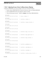
1. At the DOS prompt, type diskcopy A: A: and press Enter to copy the original GRIDLINK
installation disk to the second disk.
2. Place the source disk (GRIDLINK disk) into your floppy disk drive and press Enter.
3. Remove the source disk and place the second disk in drive A when the prompt appears.
4. Press OK.
5. Remove the backup copy of the GRIDLINK installation disk.
6. Place the original GRIDLINK installation disk in a safe place and use the new backup disk
for installations.
1.6.2.2 Copying a Disk Using Windows 3.1x
As a precaution, copy the disk and keep the original installation disk as a backup. This ensures that you
have an uncorrupted copy of all the files. You must have the original GRIDLINK installation disk and
an extra disk of the same storage capacity to perform the following procedure.
1. Start the File Manager.
2. Select the A: drive or the appropriate floppy drive letter.
3. Select Copy Disk from the File Manager’s Disk menu.
4. Click Yes when asked, “This operation will erase ALL data from the destination disk. Are
you sure you want to continue?”
5. At the “Insert Source Disk” dialog, insert the master GRIDLINK disk into your floppy disk
drive and click OK.
6. At the “Insert destination disk” dialog, remove the GRIDLINK installation disk from the
floppy disk drive and insert the new disk in the floppy disk drive.
7. Click OK.
8. Remove the backup copy of the GRIDLINK installation disk.
9. Place the original GRIDLINK installation disk in a safe place and use the new backup disk
for installations.
1-16
Rev 9/99
GRIDLINK User Manual
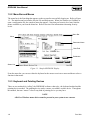
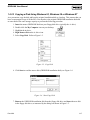
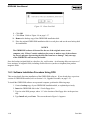
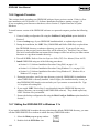
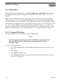
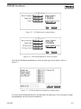
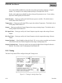
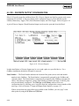
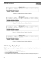
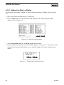
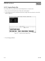
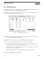
1.6.2.3 Copying a Disk Using Windows 95, Windows 98 or Windows NT
As a precaution, copy the disk and keep the original installation disk as a backup. This ensures that you
have an uncorrupted copy of all the files. You must have the original GRIDLINK installation disk and
an extra disk of the same storage capacity to perform the following procedure.
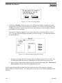
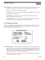
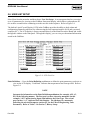
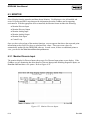
1. Insert the master GRIDLINK disk into your floppy disk drive (typically the A: drive).
2.
3.
4.
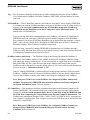
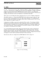
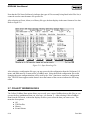
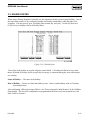
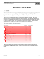
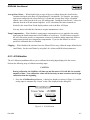
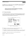
5.
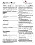
Double-click the My Computer icon on your desktop.
Highlight the A: drive.
Right mouse click on the A: drive icon.
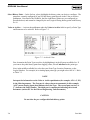
Select Copy Disk. Refer to Figure 1-3.
Figure 1-3. Copy Disk
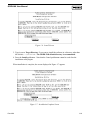
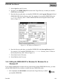
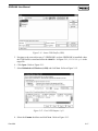
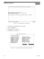
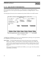
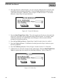
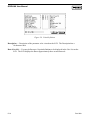
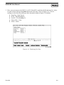
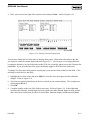
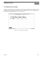
6. Click Start to read the source disk (GRIDLINK installation disk); see Figure 1-4.
Figure 1-4. Start Copy Disk
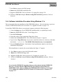
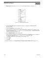
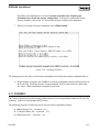
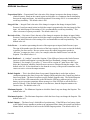
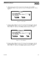
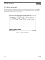
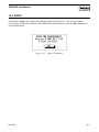
7. Remove the GRIDLINK installation disk from the floppy disk drive and insert the new disk
in the floppy disk drive, as instructed by the dialog box shown in Figure 1-5.
Rev 9/99
1-17
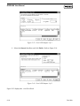
GRIDLINK User Manual
Figure 1-5. Enter New Disk
8. Click OK.
9. Click Close. Refer to Figure 1-4 on page 1-17.
10. Remove the backup copy of the GRIDLINK installation disk.
11. Place the original GRIDLINK installation disk in a safe place and use the new backup disk
for installations.
NOTICE
The GRIDLINK software is licensed for the use of the original owner on one
computer only. Fisher Controls authorizes the owner to make a copy of the software
for the sole purpose of protecting the disk files from loss or damage. Only one copy
of the GRIDLINK software may be loaded.
Store the backup (original) disk in a dust-free, dry, cool location. Avoid storing disks near sources of
heat, moisture, or magnetic fields, including electrical devices (such as a telephone) that produce
magnetic fields.
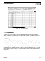
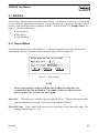
1.6.3 Software Installation Procedure Using DOS
This section details first time installation of the GRIDLINK software. If you already have a previous
version of GRIDLINK installed, refer to Section 1.6.6, Upgrade Procedure, on page 1-22.
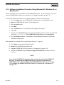
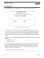
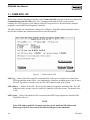
To install the GRIDLINK software on a personal computer, perform the following steps.
1. Create a backup copy of your GRIDLINK installation disk, as explained previously.
2. Insert the GRIDLINK disk in the 3.5-inch floppy drive.
3. Type A: at the DOS prompt, where “A” is the location of the floppy drive in the previous
step.
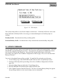
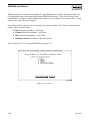
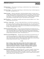
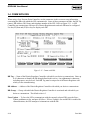
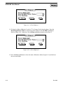
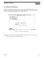
4. Type Install and press Enter. The screen shown in Figure 1-6 appears.
1-18
Rev 9/99
GRIDLINK User Manual
Figure 1-6. Install Screen
5. Type in a new Target Directory if you want to install the software in a directory other than
the default, C:\GRIDLINK. The GRIDLINK default directory is recommended.
6. Press the Install pushbutton. Note that the Cancel pushbutton cannot be used after the
installation utility begins.
When installation is complete, the screen displayed in Figure 1-7 appears.
Figure 1-7. Installation Complete Screen
Rev 9/99
1-19
GRIDLINK User Manual
7. Press Enter to return to the DOS prompt.
8. Remove the GRIDLINK installation disk.
9. Log on to GRIDLINK. Refer to Section 1.8, Logging On, on page 1-28.
10. Perform a Cold Start using the Restore config and clear history parameter. Refer to
Section 9.
1.6.4 Software Installation Procedure Using Windows 3.1x
This section details first time installation of the GRIDLINK software. If you already have a previous
version of GRIDLINK installed, refer to Section 1.6.6, Upgrade Procedure, on page 1-22.
To install the GRIDLINK software on a personal computer, perform the following steps.
1. Create a backup copy of your GRIDLINK installation disk, as explained previously.
2. Insert the GRIDLINK disk in the 3.5-inch floppy drive.
3. Start the File Manager.
4. Select the A: drive or the appropriate floppy drive letter.
5. Double-click the Install.exe file. The screen shown in Figure 1-6 appears.
6. Type in a new Target Directory if you want to install the software in a directory other than
the default, C:\GRIDLINK. The GRIDLINK default directory is recommended.
7. Press the Install pushbutton. Note that the Cancel pushbutton cannot be used after the
installation utility begins.
When installation is complete, the screen displayed in Figure 1-7 appears.
8. Press Enter to return to close the DOS install window.
9. Remove the GRIDLINK floppy disk.
10. Log on to GRIDLINK. Refer to Section 1.8, Logging On, on page 1-28.
11. Perform a Cold Start using the Restore config and clear history parameter. Refer to
Section 9.
NOTE
If you installed GRIDLINK in another directory other than the default GRIDLINK
directory, you must edit the GRIDLINK.PIF file to indicate in which directory
GRIDLINK resides. Refer to Editing the GRIDLINK.PIF in Windows 3.1x on page
1-22 or Editing the GRIDLINK.PIF in Windows 95, Windows 98, or Windows NT
on page 1-23.
1-20
Rev 9/99
GRIDLINK User Manual
1.6.5 Software Installation Procedure Using Windows 95, Windows 98, or
Windows NT
This section details first time installation of the GRIDLINK software. If you already have a previous
version of GRIDLINK installed, refer to Section 1.6.6, Upgrade Procedure, on page 1-22.
To install the GRIDLINK software on a personal computer, perform the following steps.
1. Create a backup copy of your GRIDLINK installation disk, as explained previously.
2. Insert the GRIDLINK disk in the 3.5-inch floppy drive.
3. Select the Start button.
4. Select Run.
5. Type A:\install where A: is the location of the floppy drive in step 2.
6. Click OK.
7. Type in a new Target Directory if you want to install the software in a directory other than
the default, C:\GRIDLINK. The GRIDLINK default directory is recommended.
8. Press the Install pushbutton. Note that the Cancel pushbutton cannot be used after the
installation utility begins.
When installation is complete, the screen displayed in Figure 1-7 appears.
9. Press Enter to close the DOS Install window.
10. Remove the GRIDLINK installation disk.
11. Log on to GRIDLINK. Refer to Section 1.8, Logging On, on page 1-28.
12. Perform a Cold Start using the Restore config and clear history parameter. Refer to
Section 9.
NOTE
If you installed GRIDLINK in another directory other than the default GRIDLINK
directory, you must edit the GRIDLINK.PIF file to indicate in which directory
GRIDLINK resides. Refer to Editing the GRIDLINK.PIF in Windows 3.1x on page
1-22 or Editing the GRIDLINK.PIF in Windows 95, Windows 98, or Windows NT
on page 1-23.
Rev 9/99
1-21
GRIDLINK User Manual
1.6.6 Upgrade Procedure
This sections details upgrading your GRIDLINK software from a previous version. If this is a firsttime installation, refer to Section 1.6.3, Software Installation Procedures, starting on page 1-18.
If you are updating your firmware or hardware, refer to Section 2, Update Firmware or Update
Hardware.
To install a newer version of the GRIDLINK software on a personal computer, perform the following
steps.
1. Create a backup configuration file using the GridBoss Config to Disk option detailed in
Section 2.
2. Create a backup copy of your GRIDLINK installation disk, as explained previously.
3. During the installation, the “DIR” files (COMM.DIR and Defltxx.DIR files) are placed into
the GRIDLINK directory (or whatever directory you specify). If you specify the same
directory as the previous version, these files will be written over. Therefore, if any of these
files have been modified but not renamed, their changes will be lost unless you either rename
them now or copy them to another directory.
4. Turn off all FSTs. Refer to Function Sequence Table (FST) User Manual (Form A4625).
5. Install GRIDLINK using one of the following procedures:
♦ Section 1.6.3, Software Installation Procedure Using DOS, on page 1-18.
♦ Section 1.6.4, Software Installation Procedure Using Windows 3.1x, on page 1-20.
♦ Section 1.6.5, Software Installation Procedure Using Windows 95, Windows 98, or
Windows NT, on page 1-21.
5. During the procedure, specify the same directory (typically GRIDLINK) for installation
where GRIDLINK is currently installed. After it begins, the installation utility warns you
that GRIDLINK.EXE already exists and asks you if you want to overwrite the file. Type
“a” to replace all existing files.
6. If you copied “DIR” files in Step 2, copy them back into the GRIDLINK directory (or
whatever directory you are using for the GRIDLINK software). They should replace any
“DIR” files that were just installed.
7. Restore the backup configuration file using the Disk Config to GridBoss option detailed in
Section 2.
1.6.7 Editing the GRIDLINK.PIF in Windows 3.1x
If you installed GRIDLINK in another directory other than the default GRIDLINK directory, you must
edit the GRIDLINK.PIF file to indicate in which directory GRIDLINK resides.
1. Select the Main program group window.
2. Double-click the PIF Editor icon.
1-22
Rev 9/99
GRIDLINK User Manual
3. Select Open from the File menu.
4. Navigate to the GRIDLINK.pif file located in the Target Directory in which you installed
GRIDLINK and click OK.
5. Enter the directory path where you installed GRIDLINK in the Program Filename field and
GRIDLINK.EXE after the directory path. For example, if you installed GRIDLINK in the
C:\Fisher directory, enter C:\Fisher\GRIDLINK.EXE in the Program Filename field.
Refer to Figure 1-8.
Figure 1-8. PIF Editor for Windows 3.1x
6. Enter the directory path where you installed GRIDLINK in the Start-up Directory field.
For example, if you installed GRIDLINK in the C:\Fisher directory, enter C:\Fisher in
the Start-up Directory field. Refer to Figure 1-8.
7. Select Save from the File menu.
8. Select Exit from the File menu.
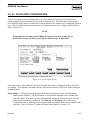
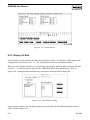
1.6.8 Editing the GRIDLINK.PIF in Windows 95, Windows 98, or
Windows NT
If you installed GRIDLINK in another directory other than the default GRIDLINK directory, you must
edit the GRIDLINK.PIF file to indicate in which directory GRIDLINK resides.
1. Select (highlight) the GRIDLINK icon located in the Target Directory in which
you installed GRIDLINK.
Rev 9/99
1-23
GRIDLINK User Manual
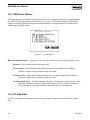
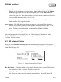
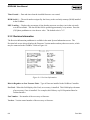
2. Right-mouse click on the GRIDLINK.EXE icon to display options as in Figure 1-9.
Figure 1-9. GRIDLINK.EXE Options
3. Click the Properties option as displayed in Figure 1-9 to display the GRIDLINK.EXE
Properties dialog.
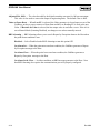
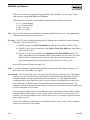
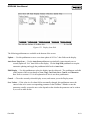
4. Click the Program tab. Refer to Figure 1-10.
5. Enter the directory path where you installed GRIDLINK in the first field. For example, if you
installed GRIDLINK in the C:\FISHER\GRIDLINK directory, enter C:\FISHER\GRIDLINK\
in the first field. Refer to Figure 1-10.
6. Enter GRIDLINK.EXE in the Cmd line field.
7. Enter the directory path where you installed GRIDLINK in the Working field. For example, if
you installed GRIDLINK in the C:\FISHER\GRIDLINK directory, enter
C:\FISHER\GRIDLINK\ in the first field. Refer to Figure 1-10.
8. Click Apply.
9. Click OK.
10. Refer to Section 1.6.9, Using Windows 95, Windows 98, or Windows NT, on page 1-25.
1-24
Rev 9/99
GRIDLINK User Manual
Figure 1-10. GRIDLINK.EXE Program
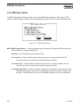
1.6.9 Using Windows 95, Windows 98, or Windows NT
When using GRIDLINK under the Windows 95, Windows 98, or Windows NT DOS prompt, it may be
necessary to adjust the Idle Sensitivity setting of the GRIDLINK.EXE file.
1. Select (highlight) the GRIDLINK.EXE icon located in the Target
Directory in which you installed GRIDLINK.
2. Right-mouse click on the GRIDLINK.EXE icon
3. Click the Properties option as displayed in Figure 1-9.
4. Click the Misc tab as displayed in Figure 1-11.
Rev 9/99
1-25
GRIDLINK User Manual
Figure 1-11. GRIDLINK.EXE Properties
5. Move the Idle sensitivity slider to Low.
6. Click Apply.
7. Click OK.
1-26
Rev 9/99
GRIDLINK User Manual
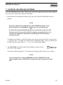
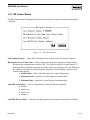
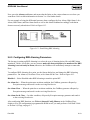
1.7 STARTING THE GRIDLINK SOFTWARE
To run the GRIDLINK software from a DOS prompt, perform the following steps (note that a GridBoss
does not need to be physically connected at this point):
1. Ensure that the current disk drive and directory is the one in which the GRIDLINK software is
installed.
NOTE
If you have added the drive and directory of the GRIDLINK software to the
PATH statement in your AUTOEXEC.BAT file, then you can skip this step.
OR
If a batch file, named GRIDLINK.BAT, has been written that sets the drive and
directory and can be located by the PATH statement, you can skip this step. See
your DOS user manual for information on modifying the PATH statement or
writing a batch file.
To change the current drive, at the DOS prompt type in the drive letter followed by a colon (such as
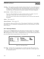
C:) and press Enter. To change the current directory, type CD followed by a space, a backslash, and
the Target Directory name (such as CD \GRIDLINK), and then press Enter.
2. Type GRIDLINK at the DOS prompt and press Enter or double-click the
GRIDLINK.EXE icon file.
The software loads and initializes. The time this tames depends on the speed of your computer.
NOTE
You can only run one version of GRIDLINK at a time. GRIDLINK does not
support multiple copies of GRIDLINK running on the same computer at the same
time.
Rev 9/99
1-27
GRIDLINK User Manual
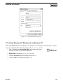
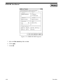
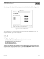
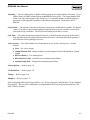
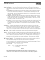
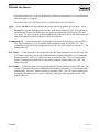
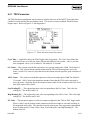
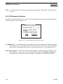
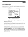
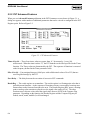
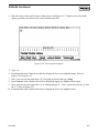
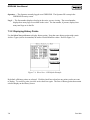
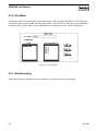
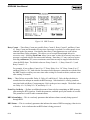
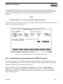
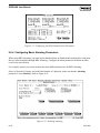
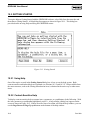
1.8 LOGGING ON
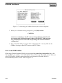
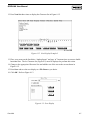
When the GRIDLINK software is loaded, the log-on screen displays as shown in Figure 1-12.
Figure 1-12. Operator Log-On Display
1. Type your assigned 3-character identifier (ID) in the Operator ID field and press Enter or Tab.
Your initials are typically your identifier. The characters show up in the field below “Operator ID”
on the screen. If identifiers have not yet been assigned, try using the default Level 1 identifier of
AAA with a Password of 1000 or the default Level 6 identifier of APC with a Password of 1234.
Identifiers are assigned by using the security features of the GRIDLINK software as explained in
Section 8.
Initially, you may access GRIDLINK and the GridBoss as the Administrator using the default
the values:
♦ Operator ID — APC
♦ Password — 1234
2. Type your assigned 4-digit Password and press Enter. For added security, the software displays an
asterisk for each number that you type. If passwords have not yet been assigned, try using the
default password of 1234. GRIDLINK compares the entered identifier and password to a list of
valid ones. If the entries are valid, further access to the software is allowed, beginning with the
initial menu bar (File and Help menus only).
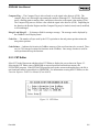
If the log-on is not valid, the following message displays:
The ID or Password is not correct, please ENTER to try again!!
1-28
Rev 9/99
GRIDLINK User Manual
Press Enter and repeat steps 1 and 2. You can repeat the procedure as many times as needed until you
successfully enter a valid Operator ID and Password. If you want to exit from the log-on screen, press
Esc. This aborts the GRIDLINK software and returns you to the point where you started GRIDLINK.
If security is enabled for the port being used by GRIDLINK to communicate with the GridBoss (such as
the local operator interface port), then your Operator ID and Password must also be valid for the unit.
For example, if you activate the Direct Connect command (which uses the local port) and security is
enabled for the local operator interface (LOI) port, your Operator ID and Password must be found in the
Security list before you are allowed to connect to the GridBoss to access the complete menu bar. Refer
to the Security function in Section 8.
NOTE
You can only run one version of GRIDLINK at a time. GRIDLINK does not
support multiple copies of GRIDLINK running on the same computer at the same
time.
Rev 9/99
1-29
GRIDLINK User Manual
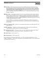
1.9 CONNECTING THE COMPUTER TO THE GRIDBOSS
The computer running the GRIDLINK software physically connects to the GridBoss through a cable.
For a local connection, this cable is typically a prefabricated operator interface cable (available from
Fisher Controls). One end of the cable (a 9-pin, D-shell, female connector) plugs into a serial
communications port on the computer running the GRIDLINK software. The other end of the cable
plugs into the GridBoss operator interface connector. This connector is a round, screw-cap-protected
connector located on the bottom of the GridBoss enclosure. Alternately, a null-modem style cable can
be connected to the LOI (Local Operator Interface) terminals on the GridBoss. A null-modem cable
links the GridBoss to the computer in place of a modem connection. It is very important that the pin
out for the null-modem cable be correct. Refer to your hardware manual concerning LOI cable pin
outs.
To connect the computer to a remotely located GridBoss controller, a serial or dial-up modem
communications line must be installed. The Host and remote GridBoss units use COM1.
Whether the computer running the GRIDLINK software is connected locally or remotely, the
communication ports on the computer and the GridBoss must be configured similarly. The computer’s
communications port is configured using the GridBoss Directory function described in Section 2.4.
The GridBoss communications port (either LOI or COM1) is configured using the Comm Ports
function in Section 9.5. The Host communications is configured using the Comm Ports Modem
function in Section 9.5.1.
If the ports on both the computer and the GridBoss are configured properly, then a Connect command
causes the computer to begin communicating with the GridBoss. For connecting to a GridBoss locally
(using the Local Operator Interface port), use the Direct Connect option of the File menu to establish
communications. The Connect command causes GRIDLINK to initiate communications with the
GridBoss by performing a search of the PC communication ports at various baud rates. GRIDLINK
locates the first Comm Port and Baud Rate that are successful in communicating with a GridBoss. See
the Direct Connect function in Section 2.3 for more information.
For connecting to a GridBoss remotely (through the Host port COM1) or to force local communications
to take place in a certain way (such as through a selected PC port or at a selected Baud Rate), use the
Connect pushbutton available through the GridBoss Directory option of the File menu. Refer to
Section 2.4 for more information.
1-30
Rev 9/99
GRIDLINK User Manual
1.10 CONFIGURATION OVERVIEW
Configuration of a GridBoss system can be performed off-line or on-line. The advantage of off-line
configuration is the ability to perform most of the configuration without connecting to the GridBoss.
This is especially an advantage if you are modifying the configuration of an operating GridBoss, since
it can minimize down time. Off-line configuration is performed by taking an existing configuration
file, opening it, and making the desired changes. See Section 2 for details on the Open function in the
File menu.
1.10.1 Configuration
The configuration procedure involves using many of the menu functions in roughly this order (note that
some may not be required for your application):
♦ System menu > Information for English or Metric unit selection
♦ System menu > Clock
♦ Grid menu > Comm with LPP, Regulator Control, and Holiday Dates (GridBoss 601 District
Regulator)
♦ Grid menu > Comm with DRs and Low Pressure Control (GridBoss 602 Low Pressure
Point)
♦ File menu > GridBoss Directory (PC communications)
♦ I/O menu > AO or DO (Two DOs acting as TDOs)
♦ I/O menu > AI (Only when AO is used)
♦ I/O menu > DI (Intrusion Switch)
♦ I/O menu > PI (Not required by the GridBoss GPC system)
♦ History menu > Setup
♦ Data menu > User List Setup (LCD display)
♦ System menu > Comm Ports (DR and LPP communications)
♦ System menu > Comm Ports > Modem (Host communications)
♦ Data menu > Radio Control
♦ Data menu > FST
♦ Utilities menu > Security
♦ System menu > Flags (for saving to internal configuration memory)
♦ Display menu > New Display
Rev 9/99
1-31
GRIDLINK User Manual
1.10.2 Duplicating a Configuration
Once you have completed the configuration for one GridBoss, you can duplicate the configuration for a
similar GridBoss by using these menu functions in the following order:
1. File > Download > GridBoss Config. to Disk which saves the configuration to a specified
file.
2. File > Direct Connect or GridBoss Directory that physically connects the second unit, and
then communicates using this function.
3. File > Download > Disk Config. to GridBoss opens the configuration file and loads it into
the second GridBoss unit.
After you have loaded configuration data into the second GridBoss (Step 3 above) and changed it as
required, you can save the configuration to its own disk file by using Step 1. Refer to Section 2 for
further information on each of the functions previously mentioned.
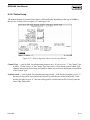
1.10.3 Communications Overview
The GridBoss system consists of LPP units, DR units, and a Host computer system. Both the LPP and
DR units communicate with the Host Computer. Communication can be originated by the Host
computer or by the LPP/DR units as an RBX. Refer to Section 9, Configuring Report-by-Exception.
The LPP unit can communicate with up to five DR units (Grid>Comm with DRs). Each DR contains
information about the LPP that validates the communication (Grid>Comm with LPP).
In each LPP, the System>Information screen is used to enter the Station name, Address and Group of
the LPP. Refer to Section 9, System Information. The System>Comm Ports>Modem screen is used to
enter the Host telephone number (Connect Command). Refer to Section 9, Modem.
In each LPP, the Grid>Comm with DRs is used to configure the DR Tag name, DR Address, DR Group
and telephone number to the DR (DR Connect Command). Each DR must be individually configured.
Use the (F2)Prev and (F3)Next pushbuttons to view each DR configuration. The Comm with DRs
screen is detailed in Section 3.
In each DR, the System>Information screen is used to enter the Station name, Address and Group of the
DR. Refer to Section 9, System Information. The System>Comm Ports>Modem screen is used to enter
the Host telephone number (Connect Command). Refer to Section 9, Modem.
In each DR, the Grid>Comm with LPP screen is used to configure the LPP Tag name, LPP Address
and LPP Group of the LPP assigned to control this DR. The Comm with LPP screen is detailed in
Section 3.
1-32
Rev 9/99
GRIDLINK User Manual
It is recommended that the DR and LPP configuration information along with the communications
parameters such as Baud Rate be configured before the units are deployed in the field. Each unit
should be marked or labeled. This allows further configuration from a central location. The Sensor
Module transducer calibrations should be recorded and if known, should be configured before the units
are deployed. It is also useful to synchronize the Date and Time in each unit. Refer to New>DR
Configuration and New>LPP Configuration in Section 2.
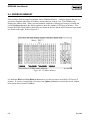
1.10.4 GRIDLINK Screen Colors
The GRIDLINK screens are made up of different types of objects, such as windows, list boxes, radio
buttons, and pushbuttons. Each type of object has its own color scheme, which is a collection of color
attributes that apply to that particular type of object. Windows, for example, have different color
attributes for the border, title, and background. Data entry objects have highlighted, normal, and
unavailable color attributes. GRIDLINK uses an array of eight color attributes to define each color
scheme. Each member of the array is a two-byte integer and is named a1, a2,…, a8. Depending on the
object type, all eight attributes may or may not be used. The default object color schemes (COLOR1
through COLOR19) and an additional custom color scheme (COLOR21) are defined in the
GRIDLINK.INI file and read when GRIDLINK is started. The color schemes and their attributes are
described next.
COLOR1 – Default Root Window
a1 = Border attribute
a3 = Title attribute
a5 = Background attribute
COLOR7 – Default Help Push Button
a1 = Active attribute
a2 = Non-active attribute
a3 = Unavailable attribute
COLOR2 – Default Window
a1 = Border attribute
a3 = Title attribute
a5 = Background attribute
COLOR8 – Default Help Window
a1 = Border attribute
a3 = Title attribute
a5 = Background attribute
COLOR3 – Default Status Window
a3 = Title attribute
a5 = Background attribute
COLOR10 – Default Push Button
a1 = Button text active
a2 = Button text non-active
a3 = Button text unavailable
a4 = Box/Border active
a5 = Box/Border non-active
a6 = Button text down
a7 = Button shadow attribute
COLOR6 – Default Help List Box
a1 = Border attribute
a2 = Non-active highlight bar attribute
a3 = Normal attribute
a4 = Active highlight bar attribute
a5 = Unavailable attribute
Rev 9/99
1-33
GRIDLINK User Manual
COLOR11 – Default Radio Button
a1 = Marker active attribute
a2 = Text normal attribute
a3 = Text unavailable attribute
a4 = Text normal when active
a5 = Text unavailable when active
COLOR12 – Default Check Box
a1 = Marker active attribute
a2 = Text normal attribute
a3 = Text unavailable attribute
a4 = Text normal when active
a5 = Text unavailable when active
COLOR13 – Default String Entry Field
a1 = Active field attribute
a2 = Non-active field attribute
a3 = Unavailable field attribute
a4 = End cap attribute
a5 = Blocked text attribute
a6 = Up/Down Spinner Buttons
a7 = Drop Down Button
COLOR14 – Default Numeric Entry Field
a1 = Active field attribute
a2 = Non-active field attribute
a3 = Unavailable field attribute
a4 = End cap attribute
a5 = Blocked text attribute
a6 = Up/Down Spinner Buttons
COLOR15 – Default Scroll-Bar
a1 = Active field attribute
a2 = Non-active field attribute
a3 = Unavailable field attribute
a4 = End arrow attribute
a5 = Border attribute
a7 = Shadow attribute
COLOR17 – Default Edit Box
a1 = Active border attribute
a3 = Normal display attribute
a5 = Non-active border attribute
COLOR18 – Default List Box
a1 = Border attribute
a2 = Non-active highlight bar attribute
a3 = Normal item text attribute
a4 = Active highlight bar attribute
a5 = Unavailable item text attribute
COLOR19 – Default Menu
a1 = Border attribute
a2 = Check mark attribute
a3 = Normal text attribute
a4 = Highlight bar attribute
a5 = Available key normal
a6 = Available key and check mark highlighted
a7 = Unavailable attribute, for all text, key, and
checkmark
COLOR21 – Template Radio Button
a1 = Marker active attribute
a2 = Text normal attribute
a3 = Text unavailable attribute
a4 = Text normal when active
a5 = Text unavailable when active
1-34
Rev 9/99
GRIDLINK User Manual
1.10.4.1 Adjusting Screen Colors for Monochrome Displays
To adjust the GRIDLINK screen colors to display correctly on a monochrome display:
1. Double-click the GRIDLINK.INI file located in the directory where you installed GRIDLINK.
2. Open the GRIDLINK.INI file using Notepad or another text editor.
3. Copy the following text into the ; Color schemes section of the GRIDLINK.INI file.
@@COLOR1
07,07,07,07,07,07,07,07,
/* Root window */
@@COLOR2
07,07,0F,0F,70,70,70,70,
/* Default window */
@@COLOR3
70,70,70,70,07,70,00,00,
/* Default status window */
@@COLOR4
0F,0F,0F,0F,70,70,70,70,
@@COLOR5
8F,8F,70,70,70,70,70,70,
@@COLOR6
70,70,07,07,70,00,00,00,
/* Default help list box */
@@COLOR7
70,70,07,07,70,00,00,00,
/* Default help push btn */
@@COLOR8
70,70,07,07,70,00,00,00,
/* Default help window */
@@COLOR9
70,70,7F,7F,70,00,00,00,
@@COLOR10
7F,70,70,00,00,00,70,00,
/* Default pushbutton */
@@COLOR11
7F,70,70,00,00,00,70,00,
/* Default radiobutton */
@@COLOR12
7F,70,70,00,00,00,70,00,
/* Default checkbox */
@@COLOR13
70,09,01,01,00,00,00,00,
/* Default string entry field */
Rev 9/99
1-35
GRIDLINK User Manual
@@COLOR14
70,09,01,01,00,00,00,00,
/* Default numeric entry field */
@@COLOR15
7F,70,70,70,70,00,70,00,
/* Default scroll-bar */
@@COLOR16
00,00,00,00,00,00,00,00,
@@COLOR17
0F,10,70,0F,07,00,00,00,
/* Default editbox */
@@COLOR18
0F,10,70,0F,07,00,00,00,
/* Default listbox */
@@COLOR19
7F,70,70,07,70,70,70,07,
/* Default menu */
@@COLOR21
7F,70,70,07,00,00,70,00,
/* Template radio button */
4. Save the GRIDLINK.INI file.
1-36
Rev 9/99
GRIDLINK User Manual
SECTION 2 — THE FILE MENU
2.1 SCOPE
This section describes how to connect the GRIDLINK Configuration Software to the GB600-Series
Controllers. This section also contains information for accessing the GridBoss controllers, creating,
saving, loading, documenting configuration files, and exiting the GRIDLINK Configuration Software.
This section contains the following information:
Information
File Menu Overview
Direct Connect
GridBoss Directory
GridBoss Directory Advanced Features
Establishing GridBoss Directory Groups
Communication Problems
New…
DR (District Regulator) Configuration
LPP (Low Pressure Point) Configuration
Open…
Collect GridBoss Data
All
TOD Profiles
Viewing TOD Profiles
Events/Alarms
History
Download…
Save GridBoss Configuration to Disk
Load Disk Configuration
Load TOD Profiles
Update Firmware
Update Hardware
Convert…
Print Configuration
GRIDLINK Security
Macros…
Exit Alt+X
Rev 9/99
Section Page Number
2.2
2-2
2.3
2-3
2.4
2-4
2.4.1
2-7
2.4.2
2-10
2.4.3
2-10
2.5
2-11
2.5.1
2-12
2.5.2
2-12
2.6
2-12
2.7
2-14
2.7.1
2-15
2.7.2
2-16
2.7.2.1
2-16
2.7.3
2-19
2.7.4
2-19
2.8
2-20
2.8.1
2-20
2.8.2
2-21
2.8.3
2-22
2.9
2-23
2.10
2-25
2.11
2-27
2.12
2-29
2.13
2-30
2.14
2-30
2.15
2-30
2-1
GRIDLINK User Manual
2.2 FILE MENU OVERVIEW
The File menu contains all functions associated with accessing the GridBoss, creating, saving, loading,
documenting configuration files, and exiting the GRIDLINK Configuration Software. The File menu
appears initially, before connecting to a GridBoss, as shown in Figure 2-1. After GRIDLINK connects
to a GridBoss, or opens a configuration file (for off-line configuration), the menu appears with the
selections displayed in Figure 2-2. For off-line configuration, the Collect GridBoss Data, Update
Hardware, Update Firmware, Print Configuration, and Download functions are unavailable.
Figure 2-1. File Menu Before Connecting
Figure 2-2. File Menu After Connecting
2-2
Rev 9/99
GRIDLINK User Manual
2.3 DIRECT CONNECT
The Direct Connect option allows you to set up communications with the GridBoss quickly if the
default communication parameters apply. For the Direct Connect option to work, security conditions
must be met, and the IBM-compatible personal computer (PC) must be connected to the LOI port of the
GridBoss with communication settings of:
♦ 8 data bits
♦ 1 stop bit
♦ No parity
Refer to Section 8 for instructions on setting the Security options.
NOTE
An LOI cable may be purchased as an accessory from Fisher Controls.
When you launch GRIDLINK, select Direct Connect to establish a connection through the LOI port of
the GridBoss currently attached to the PC. After your initial connection, you may set up other
communication parameters.
After selecting Direct Connect from the File menu, the GRIDLINK program attempts to establish
communications through COM1 of the PC at one of the following baud rates: 19200, 9600, and 4800.
If this is unsuccessful, the program then attempts to establish communications through COM2, COM3,
and COM4 of the PC, successively, until it receives a valid reply. If the link is established with the
GridBoss, the GRIDLINK menu bar is updated in keeping with the available functions.
One of two events can occur when using Direct Connect:
♦ If a communications link is established with the PC, the Status Line reads On-Line: COMx,
where x is the communications port number being used.
♦ If a communications link is not established with the PC, the message Comm Fail appears in
the Status Line, indicating that no connection could be made. You also receive the response
“No Response from GridBoss, Press Enter to continue.” In this case, you must press Enter to
release the program.
If the Direct Connect communication link fails (Comm Fail), use the GridBoss Directory feature to
establish a connection to your GridBoss. Refer to GridBoss Directory on page 2-4. The GridBoss
Directory option allows you to change your communications port, time-out settings, and other variables
used by the GridBoss units when establishing a communications link to your computer.
A Comm Fail can also occur if the GRIDLINK software stands idle for too long. In this case, simply
log back into GRIDLINK using Direct Connect or the GridBoss Directory feature.
Rev 9/99
2-3
GRIDLINK User Manual
2.4 GRIDBOSS DIRECTORY
The GridBoss Directory option allows you to select from a previously-defined group of
communications setup files that allows GRIDLINK to communicate on a personal computer to an
individual GridBoss unit. You may also add, delete, or modify these communication setups and create
new groups of GridBoss units. The GridBoss Directory communications setup files are used for setting
communications for a computer connected to the GridBoss. Directory communications can use the
LOI, COM1, or Phone Modem port at the GridBoss.
The configuration in the GridBoss Directory must match the communications configuration in the PC.
The GridBoss Directory is used to setup personal computer (PC) communications ports (COM
ports). The GridBoss Comm Ports and System Information screens are used to set up communications
for the specific GridBoss and not the PC. Refer to Section 9.
On startup, GRIDLINK uses the communications parameters configured in the first setup and in the
first communications group, COMM.DIR. These settings remain in effect until a new setup group is
selected.
After selecting GridBoss Directory from the File menu, the Open File dialog box displays, allowing you
to select the group file (*.DIR) to be opened. Refer to Figure 2-3. Typically, the group COMM.DIR is
listed first. The COMM.DIR is the group that contains the default settings for the LOI, Phone Modem,
and COM1 ports in the GridBoss.
Figure 2-3. GridBoss Directory Group Selection
2-4
Rev 9/99
GRIDLINK User Manual
Figure 2-4. PC Comm Parameters Group Dialog
When you select a group file, a list of all GridBoss communication setups in the group appears in the
Comm List, along with the PC Comm Parameters. Refer to Figure 2-4. Using this screen, you may
configure up to 40 communication setups per group. The GridBoss Directory option allows you to
change the communications port, time out settings, and other variables used by the GridBoss when
establishing a connection to your personal computer. You may also (F4)Copy and (F5)Paste similar
configurations.
NOTE
Your communications parameters must match the parameters setup on your
personal computer. Your personal computer’s communication parameters are
accessed through the computer’s Control Panel.
Comm List — Select a communications setup from the list. Upon selecting a setup from the Comm
List, you can change the communication parameters or use the Connect pushbutton to establish
communications with the associated GridBoss. Notice that three default settings are available:
♦ GridBoss LOI Deflt
♦ GridBoss COM1 Deflt
♦ Phone Modem
Connect — Establish a connection to the GridBoss using the setup currently selected in the Comm List.
After setting up your communications settings, click Connect to establish a connection from the
PC to the GridBoss.
Hangup — Hangup is used to end a communications session with a modem.
Rev 9/99
2-5
GRIDLINK User Manual
Tag — The 20-character identifier describes the use of the configured parameters for the GridBoss.
Use a default name (GridBoss LOI Deflt, GridBoss COM1 Deflt, or Phone Modem) or create
your own.
PC Baud Rate — The PC Baud Rate entered is the baud rate set in the PC and is used by GRIDLINK
to communicate with the GridBoss through a serial port (COM Port) on the PC either locally or
remotely. For successful communications, the PC Baud Rate setup in the GridBoss by
GRIDLINK and the Baud Rate set in the PC using the Control Panel must match. The
default value is 9600 Baud Rate.
If you are having difficulties communicating to your GridBoss, set both the PC Baud Rate in
GRIDLINK and your serial port (COM Port) on the Personal Computer to 9600 Baud Rate.
Your computer’s serial port (COM Port) Baud Rate can be altered from the computer’s Control
Panel. Once you have altered the PC Baud Rate in GRIDLINK, press (F8)Save. Restart the
Personal Computer. Press Connect to establish a connection.
If you are using a remote PC running GRIDLINK to communicate to a GridBoss through a
COM port, check the Baud Rate of the port by using the System Comm Ports function described
in Configuring Communications Ports in Section 9.
GridBoss Address and Group — The GridBoss Group is the Group with which the GridBoss is
associated. The GridBoss Address is the Address of the specific GridBoss within the Group
with which you desire to communicate. If you are connected to a multi-drop series of GridBoss
units (either DRs or LPPs), enter the exact and unique Address and Group of that specific
GridBoss to talk to that device or use the default values of 240. Refer to the System Information
screen in Section 9. Valid entries include 1 - 247.
If the PC running GRIDLINK is connected directly to the operator interface (LOI) port on the
GridBoss, a GridBoss Group of 240 and a GridBoss Address of 240 (the default values) allows
access to the GridBoss no matter what Address and Group are configured in the GridBoss.
For a Host port (COM1 Port) on the GridBoss, the configured GridBoss Address and
GridBoss Group used by GRIDLINK must match the Address and Group configured in
the System Information screen. Refer to Section 9.
PC Comm Port — This parameter selects the communications port on the Personal Computer to be
used by GRIDLINK. The communications port is only for the setup currently selected in the
Comm List. For successful communications, the PC Comm Port set up in GRIDLINK and
the COM Port set up using the Control Panel on the Personal Computer must match. The
GridBoss can communicate through COM1, COM2, COM3, or COM4 of the PC, depending on
your computer’s configuration. Your computer’s serial port (COM Port) can be altered from the
computer’s Control Panel.
For a Host port (COM1 Port) on the GridBoss, the configured GridBoss Comm Ports
settings used by GRIDLINK must match the Host port set in the remote Personal
Computer. Refer to Section 9.
2-6
Rev 9/99
GRIDLINK User Manual
IRQ — This parameter selects the hardware Interrupt Request (IRQ) setting on the Personal Computer.
The IRQ must not conflict with the serial or bus port used by a mouse or other peripheral device
connected to additional communication ports. For successful communications, the IRQ set
up in GRIDLINK must match the IRQ set up for the COM Port being using on the PC.
You can view the PC’s serial port (COM Port) IRQ from the Windows Control Panel (in
Windows 95, 98, or NT), Select Start, Settings, Control Panel, System, Device Manager, open
Ports, select desired Com port, click Properties, and finally view the Resources tab).
After setting up your communications settings, click Connect to establish a connection from the PC to
the GridBoss.
If a communications link is established with the PC, the Status Line reads On-Line: COMx, where x is
the communications port number being used.
If the communications link is not established with the PC, the message Comm Fail appears, indicating
that no connection could be made. You also receive the response “No Response from GridBoss, Press
Enter to continue.” In this case, you must press Enter to release the program. You must reconnect to
the GridBoss.
NOTE
If the GridBoss remains idle for too long, you may receive the timeout error “No
Response from GridBoss, Press Enter to continue.” In this case, you must press
Enter to release the program. You must reconnect to the GridBoss.
2.4.1 GridBoss Directory Advanced Features
When you select a setup in the Comm List and press the Advanced Features pushbutton, a dialog box
appears. Refer to Figure 2-5.
Figure 2-5. GridBoss Directory Advanced Features
Rev 9/99
2-7
GRIDLINK User Manual
Mode — Indicates the type of communications being implemented. Setting this parameter to Dialup
enables sending the initialize, dial, and hang-up commands to an AT command set-compatible
modem. Setting this parameter to Radio bypasses the modem commands and uses normal
communications. Radio is used for any non-modem type communications.
Retries — This parameter (default is “5”) can be set from “0” to “25” to control the number of times
after the initial try that the GRIDLINK software attempts to establish communications with the
specified GridBoss before reporting a timeout error. The amount of time between retries can be
adjusted by using the Timeout parameter. Adjust the Retries value up if you are having
trouble communicating with your GridBoss.
TX Delay — The TX Delay has a default value of “0.05” seconds. The TX Delay enables the RTS line
for the amount of configured delay periods before transmitting data. The delay periods can be
set in 0.050-second increments. A delay is typically used to allow a radio or modem to fully
enable the transmit mode before data is applied to transmit. In direct wire communications, this
value should be set to 0 or 0.05 seconds.
Keyoff Delay — Defines the amount of time to delay before transmitting a response once a valid
message has been received and the period to delay before turning the RTS signal off (key-off
delay). The default Keyoff Delay is 0 seconds.
Timeout — This is the actual amount of time the GRIDLINK software waits between retries when
attempting to communicate through a Comm Port with a GridBoss. The default time-out is
0.50 seconds, but this can be increased up to 255 seconds if you are having difficulties
communicating with your GridBoss. The communications port requires at least a 0.25-second
timeout. Do not enter 0 (zero) in the Timeout field.
GRIDLINK Address — The GRIDLINK Address at the PC has a default value of 3. If more than one
computer with GRIDLINK is communicating with a group of GridBoss units, either by radio or
by other multi-drop communications, the GRIDLINK Address of each GridBoss must be unique
to avoid multiple responses. The GRIDLINK Address must also be different from any other
Host system that may access the network. Valid entries include 1 to 247.
GRIDLINK Group — The GRIDLINK Group address at the PC has a default value of 1. In the
assignment of GRIDLINK Group addresses, the following convention should be used:
Group 0
Reserved, DO NOT USE
Group 1
Host Devices
Group 2 - 99
GRIDLINK Group numbers available
Group 100
Reserved for testing (no CRC in GRIDLINK)
Group 101 - 239
GRIDLINK Group numbers available
Group 240
Reserved
Group 241 - 247
GRIDLINK Group numbers available
2-8
Rev 9/99
GRIDLINK User Manual
Initialize Command — This command initializes the modem to the desired operation parameters. A
typical command for AT command set modems is shown in the following example. Refer to the
modem manufacturer’s instructions for more information.
Initialize Command
where:
~~~
+++
ATxxx
~~~+++~~~ATxxx
= 3 second pause
= send escape code to modem
= disconnect and perform software reset; xxx depends on the type of
modem, but some modems use the same command as for hang-up.
Dial Command — This command provides the modem with a telephone number to dial out. This is
the telephone number of the GridBoss with which GRIDLINK is trying to communicate. A
typical command for AT command set modems is shown in the following example. Refer to the
modem manufacturer’s instructions for more information.
Dial Command
where:
ATDT 18005151212
ATDx = dial the number 1-800-515-1212
T = tone dialing
NOTE
The telephone numbers must include the exact sequence required at the PC. In
certain cases, access numbers such as (9) and area codes (1-212) may be required.
Hang Up Command — This command provides the modem with commands for an orderly disconnect
or hang-up sequence. A typical command for AT command set compatible modems is the same
as the initialize command. Refer to the modem manufacturer’s instructions for more
information.
Hang Up Command ~~~+++~~~ATZH0
where:
~~~
+++
ATZH0
Rev 9/99
= 3 second pause
= send escape code to modem
= disconnect and perform software reset
2-9
GRIDLINK User Manual
2.4.2 Establishing GridBoss Directory Groups
The GridBoss Directory option allows you to select from a previously defined group of communication
setups. This option allows the GRIDLINK program to talk to individual GridBoss units and to add,
delete, or modify these setups. You may also create new groups of GridBoss units. The following
section details establishing GridBoss groups and individual GridBoss communications setups.
1. Select GridBoss Directory from the File menu. Refer to Figure 2-2.
2. Select the group File Name in the Files field for the group you desire to alter or select the
default COMM.DIR. Refer to Figure 2-3.
3. Enter all Personal Computer communications information and Advanced Features if
necessary. Refer to Figure 2-4 and Figure 2-5.
4. Press (F8)Save.
5. Press Connect to establish a connection.
2.4.3 Communication Problems
Occasionally, you may need to alter your GridBoss Directory options when you are having problems
communicating with your GridBoss.
1. Select GridBoss Directory from the File menu. Refer to Figure 2-2.
2. Select the group File Name in the Files field for the group you desire to alter or select the
default COMM.DIR. Refer to Figure 2-3.
3. Select an existing file in the Comm List to alter a file or select Default to create a new
communications file.
4. Place your cursor in the Tag field and enter a new configuration name if necessary.
5. Verify that the PC Baud Rate, PC Comm Port, and IRQ address match the values setup in
your Personal Computer’s Control Panel. If they do not match, alter the appropriate values
in GRIDLINK. Refer to Figure 2-4 and the parameter descriptions in section 2.4.
6. Set the GridBoss Address to 240 when using the LOI port or the specific GridBoss
Address of the remote GridBoss with which you desire to communicate.
7. Set the GridBoss Group to 240 when using the LOI port or the specific GridBoss Group
of the remote GridBoss with which you desire to communicate.
8. Press the Advanced Features pushbutton. Refer to Figure 2-5.
9. Enter 10 in the Retires field.
10. Enter 1 in the Timeout field.
11. Press OK.
12. Press (F8)Save.
13. Press Connect.
2-10
Rev 9/99
GRIDLINK User Manual
2.5 NEW…
Use New… in the File menu and select DR Configuration (GB601) or LPP Configuration (GB602) to
set up a new configuration for a GridBoss that is not connected to GRIDLINK. Available configuration
parameters can be specified using the GRIDLINK software menu selections. You configure the
GridBoss configuration file as if you were connected to the device; the main difference is that functions
requiring a live connection, such as AI Calibrations, are unavailable in this mode.
When values are saved during this off-line configuration, they are saved to a GridBoss configuration
file with the extension .GFC in the default GRIDLINK directory unless you specify otherwise. Once
the file is created, it automatically becomes active and you may edit the file. The configuration file
may also be loaded into a GridBoss later using the Disk Config. to GridBoss function. Refer to Load
Disk Configuration to GridBoss on page 2-21.
Configuration of a GridBoss system can be performed off-line or on-line. The advantage of off-line
configuration is the ability to perform most of the configuration without connecting to the GridBoss.
This is especially an advantage if you are modifying the configuration of an operating GridBoss, since
it can minimize down time. Off-line configuration is performed by taking an existing configuration
file, opening it, and making the desired changes.
It is recommended that the DR and LPP configuration information along with the communications
parameters such as Baud Rate be configured before the units are deployed in the field. Each unit
should be marked or labeled. This allows further configuration from a central location. The Sensor
Module transducer calibrations should be recorded and if known, should be configured before the units
are deployed. It is also useful to synchronize the Date and Time in each unit.
Enter the name of the new configuration in the File Name field. Refer to Figure 2-6.
Figure 2-6. Save File Dialog
Rev 9/99
2-11
GRIDLINK User Manual
After entering the File Name and pressing OK, the new file is created. At this point, the new file is
open and you may proceed to the appropriate menu items to configure off-line. The File Name displays
on the Status Line at the bottom of the screen to indicate the file being used. Note that you see default
values, such as found in a previously un-configured GridBoss, in the off-line configuration screens.
2.5.1 DR (District Regulator) Configuration
Use the DR Configuration option to create a new configuration file for the District Regulator Controller
while off-line. Off-line configuration files are useful as you can create the files in your office and you
can use the files for DRs that have the same basic configuration.
The DR computes load profiles based on ambient temperature and time-of-day to determine the
“predicted” Setpoint of the regulator. The RTD reads the ambient temperature. The GridBoss uses the
Sensor Module (SM) to acquire the inlet and outlet pressure from the District Regulator.
2.5.2 LPP (Low Pressure Point) Configuration
Use the LPP Configuration option to create a new configuration file for the Low Pressure Point
GridBoss 602 while off-line. Off-line configuration files are useful as you can create the files in your
office and you can use the files for LPPs that have the same basic configuration. The advantage of offline configuration is the ability to perform most of the configuration without connecting to the
GridBoss. This is especially an advantage if you are modifying the configuration of an operating
GridBoss, since it can minimize down time.
The Low Pressure Point GridBoss 602 is located downstream from the District Regulator. The Low
Pressure Point (LPP) uses the Sensor Module (SM) sensor to acquire the pressure from the low pressure
point in the gas distribution system.
2.6 OPEN…
The Open option allows you to open an existing file. After you select Open from the File menu, a submenu appears as in Figure 2-7, allowing you to select one of the following types of files to open:
♦
♦
♦
♦
♦
♦
2-12
Event File – extension .EVT
Alarm File – extension .ALM
Minute History File – extension .MDB
15-Minute History File – extension .PDB
Daily History File – extension .DAY
GridBoss Config. File – extension .GCF
Rev 9/99
GRIDLINK User Manual
Figure 2-7. Open Menu Options
After selecting the type of file to open, the Open File dialog box displays to allow you to select the file.
Refer to Figure 2-8.
Use the Up (↑) and Down (↓) arrow keys to select the desired file in the Files list and then press Enter
or press OK. If the desired file is not listed, you can use the scrollable list box on the right to select a
drive and directory that has the file you desire. Note that the root directory of a drive is indicated
simply by two periods (..). The current drive and directory are displayed below the File Name field.
Figure 2-8. Open File Dialog Box
Rev 9/99
2-13
GRIDLINK User Manual
Note that the File Name field merely indicates the types of files currently being listed in the Files list; it
cannot be used to enter the name of a specific file.
After selecting an Event, Alarm, or a History file type, the data displays in the same format as live data.
Refer to Figure 2-9.
Figure 2-9. Open Event Log File
After selecting a configuration file type, you may proceed with configuration from the Grid menu, I/O
menu, and Data menu as if connected to a GridBoss unit. Select the default configuration file to edit,
changing the point configuration that will be used by the “New” function to create new configuration
files. The File Name appears on the Status Line at the bottom of the screen to indicate the file being
edited.
2.7 COLLECT GRIDBOSS DATA
The Collect GridBoss Data option allows you to easily save various GridBoss data to disk files (or you
can use the Save pushbutton when you view logs—see Section 7). After selecting Collect GridBoss
Data from the File menu, a sub-menu displays to allow you to select the data you want to save. The
menu has four options:
♦ All
♦ TOD Profiles
♦ History
♦ Events/Alarms
2-14
Rev 9/99
GRIDLINK User Manual
After selecting “All,” a default File Name displays in the Save File dialog box. Refer to Figure 2-10.
Figure 2-10. Collect GridBoss Data
You can either accept the default File Name or enter a new name under which the file is saved. To
change the File Name, type over the existing name.
2.7.1 All
“All” saves:
♦ Time-of-Day (TOD) load profiles report under FILENAME.TOD. (DR only)
♦ 15 Minute History values under FILENAME.PDB.
♦ Daily History values under FILENAME.DAY.
♦ Events under FILENAME.EVT.
♦ Alarms under FILENAME.ALM.
When you select All or any other option under Collect GridBoss Data, the associated files are created
immediately in the default GRIDLINK directory. The Collect GridBoss Data (All) function retrieves
the data and stores it in disk files, such as those with an .TOD extension
Rev 9/99
2-15
GRIDLINK User Manual
2.7.2 TOD Profiles
When using a District Regulator GB601, the Collect GridBoss Data (TOD Profiles) function retrieves
the detailed time-of-day load profiles and stores it in disk files, such as those with a .TOD or .PRN
extension.
When you select TOD Profiles, all time-of-day load profiles associated with the District Regulator
GB601 controller are saved. The first Save File dialog box allows you to enter the File Name for the
.TOD files, which are used by the GridBoss. After a short time, a second Save File dialog box displays.
The second Save File dialog box allows you to enter the File Name for the .PRN files which are used by
you. The .PRN file is the time-of-day profile formatted in a spreadsheet format. A .PRN file can be
imported into Microsoft® Excel or other spreadsheet application. You can than use the data to create a
graphical representation of your data. Refer to Section 2.7.2.1, Viewing TOD Profiles, on page 2-16.
2.7.2.1 Viewing TOD Profiles
Time-of-day profiles can be saved and viewed in spreadsheet format.
NOTE
The following process describes how to load a TOD Profile using Microsoft Excel.
The spreadsheet application with which you are using may differ from the
following example.
To view a TOD Profile in Excel:
1. Save a TOD Profile using the Collect GridBoss Data function described in Section 2.7 on
page 2-14.
2. Launch Excel.
3. Select Open from the File menu.
4. Select All Files from the Files of Type drop-down list box located at the bottom left of the
screen. Refer to Figure 2-11.
2-16
Rev 9/99
GRIDLINK User Manual
Figure 2-11. Locate TOD Profile (.PRN)
5. Navigate to the correct directory (C:\GRIDLINK\ or where GRIDLINK is installed) where
the TOD Profile is stored and select the .PRN file. In Figure 2-11, 02250908.prn is the
target file.
6. Click Open. Refer to Figure 2-11.
7. Select Delimited and Windows (ANSI) and click Next. Refer to Figure 2-12.
Figure 2-12. Excel .PRN Import 1 of 3
8. Select the Comma checkbox and click Next. Refer to Figure 2-13.
Rev 9/99
2-17
GRIDLINK User Manual
Figure 2-13. Excel .PRN Import 2 of 3
9. Select the General checkbox and click Finish. Refer to Figure 2-14.
Figure 2-14. Excel .PRN Import 3 of 3
Figure 2-15 displays the .PRN file in Excel.
2-18
Rev 9/99
GRIDLINK User Manual
Figure 2-15. TOD Profile in Excel
2.7.3 Events/Alarms
When you select Events/Alarms, the Collect GridBoss Data function saves all 240 events and 240
alarms. Events under are saved under the FILENAME.EVT and Alarms are saved under FILENAME.ALM.
2.7.4 History
After selecting Collect GridBoss Data from the File menu and selecting History, the Collect GridBoss
Data function saves 15-minute and daily data for all parameters configured in the history database (up
to 15). When you select History, the Save File dialog box displays as described previously. Change the
current File Name or accept the default name and press OK.
Next, a dialog box for selecting the number of logs displays. Refer to Figure 2-16. Note that 840 logs
are 96 15-minute logs stored each day times 8.75 days. If you wanted just the past 2 days of 15-minute
history, you would multiply 96 times 2 to get 192 logs. Enter the number of logs you desire to collect
and press OK.
Rev 9/99
2-19
GRIDLINK User Manual
Figure 2-16. Select Number of Logs
2.8 DOWNLOAD…
Use Download... in the File menu to create a back up copy of the configuration for a GridBoss on a disk
file, or to upload a configuration file to a GridBoss. The Download option allows you to download the
configuration from a GridBoss unit to a disk file, or a disk configuration to a GridBoss.
After selecting Download from the File menu, a sub-menu displays:
♦ GridBoss Config. to Disk – Download the current GridBoss configuration to a disk file.
♦ Disk Config. to GridBoss – Upload a disk configuration to a GridBoss.
♦ TOD Profiles – Upload the time-of-day load profiles to a GB601 DR.
2.8.1 Save GridBoss Configuration to Disk
The GridBoss Config. to Disk option saves the current configuration of the connected GridBoss to a
disk file.
1. Select GridBoss Config. to Disk. The Save File dialog box appears. Refer to Figure 2-6.
2. Type the File Name of the backup file or use the default name, which is based on the Group
and Address of the device.
3. Press OK. A file with a .GCF extension is created in the default GRIDLINK directory.
The default GRIDLINK directory is the directory from which you launched the GRIDLINK
program.
The GridBoss Config. to Disk .GCF file contains the full configuration of the GridBoss, except for
any FSTs. To save FSTs, you must use the FST Editor and save the FSTs to a disk file.
NOTE
Back up FSTs by using the Write FST function in the FST Editor.
2-20
Rev 9/99
GRIDLINK User Manual
This feature is especially useful when multiple GridBoss units requiring similar configurations are
being configured for the first time, or when configuration changes need to be made off-line. The
advantage of off-line configuration is the ability to perform most of the configuration without
connecting to the GridBoss. This is also an advantage if you are modifying the configuration of an
operating GridBoss, since it can minimize down time. Off-line configuration is performed by taking an
existing configuration file, opening it, and making the desired changes.
Once a backup configuration file is created, it can be loaded into a GridBoss by using the Disk Config.
to GridBoss function. GB601 District Regulator units can only load DR files, while GB602 Low
Pressure Point units can only load LPP files.
2.8.2 Load Disk Configuration to GridBoss
The Disk Config. to GridBoss option loads GridBoss configuration data from a disk file into a
connected GridBoss. This dialog box lists the configuration files with the .GCF located in the default
GRIDLINK directory.
1. Select Disk Config. to GridBoss from the Download option located in the File menu. The
Open File dialog box appears. Refer to Figure 2-8.
2. Select one of the listed files with a .GCF extension, or choose a different Drive/Directory that
contains the desired configuration file.
3. Press OK.
Another dialog box appears that lets you select various components of the configuration to be
loaded into the GridBoss. Refer to Figure 2-17. The File Name of the configuration file is
given at the top of the dialog box. Only the point types that are configured both in the GridBoss
and in the disk file are selectable in the list.
4. By default, all components are selected; if you do not disable any, all point types download
and override the current configuration. To deselect a component, such as System Variables,
click on the “X” between the brackets in front of the component.
Rev 9/99
2-21
GRIDLINK User Manual
Figure 2-17. Disk Config. to GridBoss Selection for a District Regulator
5. When you are finished selecting components, press (F8)Download.
CAUTION
Counters, accumulators, and EU values are changed during a download if
the current value is different from the value on the disk file. Make sure that
any controlled process is safe from abrupt changes due to the downloaded
configuration.
6. Keep in mind that FSTs are not part of the configuration file. Load any FSTs into the
GridBoss by using the Read FST function in the FST Editor.
2.8.3 Load TOD Profiles
When using a District Regulator GB601 unit, this option loads time-of-day load profiles from a disk
file into GB601 user memory. Select TOD Profiles from the File menu’s Download option. When you
select TOD Profiles, a display appears that allows you to download a Weekday Profile, a
Weekend/Holiday Profile, or both. Refer to Figure 2-18.
2-22
Rev 9/99
GRIDLINK User Manual
Figure 2-18. TOD Profiles
Time-of-day load profiles are used in the Adaptive control mode. A Weekday Profile has a lower load
than a Weekend or Holiday Profile as less energy is consumed during the week while people are
working.
Weekday Profile – Downloads time-of-day weekday profile.
Weekend/Holiday Profile – Downloads time-of-day weekend and associated holiday load profile.
2.9 UPDATE FIRMWARE
Use the Update Firmware option located under the File menu to update the internal software. Only the
Flash ROM is upgraded during this procedure. This option does not update the GRIDLINK software
but clears the Event Log and Alarm Log. Save the Event Log and Alarm Log to a file before
proceeding; refer either to Save GridBoss Configuration to Disk on page 2-20, or to Event and Alarm
History in Section 7.
You receive the updated firmware files on a disk. To install the file and update your firmware:
1. Create a backup copy of the GRIDLINK Update Firmware disk, as explained previously.
2. Perform a full backup before proceeding; refer to Save GridBoss Configuration to Disk on
page 2-20.
3. Insert the Update Firmware disk in the 3.5-inch floppy drive.
4. Read the README file included on the Update Firmware disk.
5. Select Update Firmware from the File menu. The New or Existing Backup dialog box appears
for specifying whether to create a new backup or use an existing file.
Rev 9/99
2-23
GRIDLINK User Manual
Figure 2-19. New or Existing Backup
6. Click New or Existing. When you create a New backup, the GridBoss reinstalls the current
configuration of the device after the hardware is installed. If you choose Existing backup, the
GridBoss reinstalls the configuration based on the last backup you created and does not return
the GridBoss to its current state.
The Open File dialog box appears for specifying a File Name to download. Refer to Figure
2-20. The Open File dialog displays the names of all files with the .BIN extension located in
the default directory.
Figure 2-20. Update Firmware Open File Dialog
7. Navigate to the floppy disk drive location where the Update Firmware file is located. You
can change the path to the directory containing the file using the Directory/Drive field.
8. Select the desired file from the Files list, which is the file on the floppy disk. The file has a
.BIN extension. With the desired file highlighted, press OK.
The file begins loading, with the Status Line showing the progress in four categories: Segment,
Address, Block Size, and Total Sent. The loading process may take several minutes depending on the
firmware.
2-24
Rev 9/99
GRIDLINK User Manual
When loading is complete, the GridBoss re-reads its configuration and records the actions in the Event
Log. While the memory is being modified, the I/O is not read, but is held at the last values. When
installation is complete, press Enter.
2.10 UPDATE HARDWARE
Use Update Hardware under the File menu to make a major modification to the hardware of the
GridBoss, such as replacing the motherboard, replacing the flash chip, replacing the entire GridBoss
unit, or any other modification in which you are concerned that configuration will be lost. After
selecting the Update Hardware option, backup files are created containing the GridBoss configuration,
calibration, communications settings, GridBoss flags, and FSTs. Alarms, events, and history cannot be
loaded back into the unit, if you require the information, be sure to save the logs to a file before
proceeding. Refer to Section 2.7, Collect GridBoss Data, on page 2-14.
After backing up the information, you are prompted to power down the unit, make the hardware
changes, power the unit back up, and then press Enter. At that time, the backup information is loaded
into the GridBoss.
When loading of the files is complete, GRIDLINK re-connects to the GridBoss re-reads its
configuration and records the actions in the Event Log.
To update your hardware:
1. Select Update Hardware from the File menu. Refer to Figure 2-21.
Figure 2-21. Update Hardware Backup
2. Click New or Existing. When you create a New backup, the GridBoss reinstalls the current
configuration of the device after the hardware is installed. If you choose Existing backup,
the GridBoss reinstalls the configuration based on the last backup you created and does not
return the GridBoss to its current state.
GRIDLINK automatically begins saving the hardware configuration.
Rev 9/99
2-25
GRIDLINK User Manual
Figure 2-22. Saving Hardware Configuration
3. When prompted, remove power from the GridBoss.
4. Replace the hardware.
5. Reapply power to the GridBoss.
6. Press Enter. Refer to Figure 2-23.
Figure 2-23. Configuration Selection for a District Regulator
2-26
Rev 9/99
GRIDLINK User Manual
By default, all components are selected; if you do not disable any, all point types
download and override the current configuration. To deselect a component, such as
System Variables, click on the “X” between the brackets in front of the component.
7. When you are done selecting components, press (F8)Download.
Figure 2-24. Updating Hardware
The loading process may take several minutes depending on how large the backup configuration file is.
8. When loading is complete, the GridBoss re-reads its configuration and records the actions in
the Event Log. While the memory is being modified, the I/O is not read, but is held at the
last values. When installation is complete, press Enter.
2.11 CONVERT…
The Convert option converts the existing GridBoss history files to a spreadsheet format file for easy file
exporting. Convert is located under the File menu.
The following categories of data logs can be converted into a spreadsheet format:
♦ Minute History File – extension .MDB
♦ 15-Minute History File – extension .PDB
♦ Daily History File – extension .DAY
Rev 9/99
2-27
GRIDLINK User Manual
When you select any of the previous options, the Open File dialog box (Figure 2-8) appears with a list
of all applicable history files found in the default GRIDLINK directory. These files must have been
created either by using the Collect GridBoss Data function or by using the Save function while viewing
a history log. Select the desired log file.
Once a history file is selected, a new screen appears as shown in Figure 2-25. Select a conversion file
format. There are four formats:
♦
♦
♦
♦
Tab delimited spreadsheet – ASCII text
Comma delimited spreadsheet – ASCII text
Space delimited spreadsheet – ASCII text
Intellution Format (15-minute or day history only)
Refer to Section 2.7.2.1, Viewing TOD Profiles, on page 2-16.
Figure 2-25. Convert
2-28
Rev 9/99
GRIDLINK User Manual
Select a format and press Start Converting. A Save File dialog box appears (refer to Figure 2-6) that
lets you specify the File Name of the spreadsheet file and the intended location. Use the DOS naming
conventions when naming your files. You may specify a file name with up to eight characters before
the period and an extension with three characters after the period: for example, Convert2.txt or
History2.txt. When you press OK, the file is created.
Start Converting — After selecting the type of conversion format, press Start Converting to convert
the files.
Cancel — Press Cancel to exit the Conversion screen.
2.12 PRINT CONFIGURATION
Select the Print Configuration option in the File menu to print the current configuration to the default
on-line printer. Refer to Figure 2-26.
Figure 2-26. Print Configuration for GB601 DR Controller
Select the configuration variables you desire to print and press F8(Print) to print your selections.
Rev 9/99
2-29
GRIDLINK User Manual
NOTE
The printer must be a line printer. Print Configuration does not support PostScript
printers.
2.13 GRIDLINK SECURITY
The GRIDLINK Security feature is available from the initial File menu before you connect to the
GridBoss. Select the GRIDLINK Security option in the File menu to edit the log-ons of all users of the
GRIDLINK software on this PC. In the screen that appears, you can specify the Operator ID,
Password, and Level of up to 21 different users. Refer to Section 8 for more information.
2.14 MACROS…
The Macros… feature is available from the initial File menu before you connect to the GridBoss.
Use macros to record a sequence of keystrokes that you perform. You can then replay the sequence of
keystrokes on demand by using a “hot key” that you assign before recording the sequence of
keystrokes. The macro options are:
♦ Record Macro
♦ Play Macro
♦ Stop Recording
Refer to Section 8 for detailed instructions on creating macros.
2.15 EXIT ALT+X
Select Exit under the File menu to exit the GRIDLINK program. If you are currently connected to a
disk file, the file will be closed. If you are currently connected to a dial-up GridBoss, the hang-up
command will be issued to the modem.
When you select Exit, the GRIDLINK software quits running and disappears from the screen.
Alternately, you can use the Alt + X key combination when in the majority of screens to perform the
same action.
2-30
Rev 9/99
GRIDLINK User Manual
SECTION 3 – THE GRID MENU
The Grid menu allows you to set up parameters that are used to communicate between the District
Regulator (DR) controller and the Low Pressure Point (LPP) controller as well as to establish
parameters for the control loops. The Grid menu is different for the DR and the LPP units. The
following information is included in this section.
Information
Comm with LPP
RBX Alarm Options
Regulator Control
RBX Alarm Options
I/O Definitions
Tuning
Adaptive
Holiday Dates
Comm with DRs
DR Control Status
RBX Alarm Option
Low Pressure Control
Rev 9/99
Section
3.1
3.1.1
3.2
3.2.1
3.2.2
3.2.3
3.2.4
3.3
3.4
3.4.1
3.4.2
3.5
Page Number
3-2
3-4
3-5
3-8
3-8
3-10
3-13
3-15
3-16
3-19
3-20
3-21
3-1
GRIDLINK User Manual
3.1 COMM WITH LPP
When using a District Regulator Controller, select Comm with LPP under the Grid menu to display the
Communications with the LPP screen. The Communications with the LPP screen is used to
configure the LPP Tag (name), LPP Address, and LPP Group of the Low Pressure Point Controller
assigned to control this District Regulator Controller.
The LPP controller can communicate with up to five DR units. Each DR contains information about
the LPP that validates the communications between the DR and LPP.
Figure 3-1. Comm with the LPP
LPP Tag — Name of the LPP assigned to control this DR. Enter up to 10 characters to identify the
LPP being defined in this screen. Any alphanumeric characters, including spaces, may be used.
The LPP Tag must be a unique value for each LPP Controller used in the system.
LPP Address — Address of the LPP. This is the LPP Address assigned to control this DR. The LPP
Address must be a unique value for each LPP Controller used in the system. The default value
is 200.
LPP Group — Group with which the LPP is associated and LPP Group assigned to control this DR.
The default value is 2.
NOTE
If the LPP Address and LPP Group entered here do not match the DR Address and
DR Group of the LPP that controls this DR, the DR ignores the commands.
3-2
Rev 9/99
GRIDLINK User Manual
DR Port to LPP — Select the communications port at the DR. This is the communications port the
DR uses to communicate with the LPP. The default value is COM1.
Alarms — You can either enable or disable limit alarm logging for the Low Pressure Point controlling
this DR. If you enable Alarms, the RBX Alarm Options pushbutton becomes active. The LPP
Communications Fail alarm is the only alarm that can be logged to the Alarm Log. If you
disable Alarms, no alarm logging is generated for this LPP, regardless of the alarm
configuration. The default value is Enabled.
Last LPP Comm Time — Displays the last date and time the Low Pressure Point Controller had valid
communications with this District Regulator.
Last LPP Press Value — Displays the last average low pressure for the minute (Avg. Low Press
Value) point value read at the LPP.
Last Setpoint Change — Displays the last change in Setpoint received from the LPP.
DR Setpoint at Last Comm Time — Displays the state of the Setpoint and Control Output at the
District Regulator Controller when the last communications with the LPP occurred.
♦ Within Limits – DR is within the Setpoint and Control Output limits.
♦ Maximum Limit – Setpoint or Control Output at maximum limit.
♦ Minimum Limit – Setpoint or Control Output at minimum limit.
Active LPP Alarms — This field indicates any alarms that are active from the LPP Controller. When
alarming is Enabled, the limit alarms that are active appear. Even if the Alarms field is
Disabled, all alarm indicators can still appear. You may see the following:
♦ None – No active alarms.
♦ Low Bat – Low battery alarm.
♦ Pressure Xmit – Low pressure transmitter point failure.
♦ Comm Fail – Communications failure.
Rev 9/99
3-3
GRIDLINK User Manual
3.1.1 RBX Alarm Options
Communications with the LPP can be tracked by the Host by sending a Report-by-Exception alarm to
the Host when a set of conditions is met.
Figure 3-2. RBX Alarm Options
RBX on LPP Comm Alarm — Set the appropriate type of Report-by-Exception (RBX) alarm.
Disabled – Select Disabled to turn this option OFF. This is the default value.
On Alarm Set – When the LPP enters a communications alarm condition, the GridBoss
generates a Report-by-Exception message to the Host.
On Alarm Clear – When the LPP leaves a communications alarm condition, the GridBoss
generates a Report-by-Exception message to the Host.
On Alarm Set & Clear – In either condition, a Report-by-Exception message generates. Note
that RBX alarming also requires the communications port to be properly configured.
Select Disabled if you do not want RBX alarming to be active for this point.
RBX on LPP Alarms — Select Disabled or Enabled to allow Report-by-Exception (RBX) alarming
when the Low Battery or Pressure Point Fail type of LPP alarm occurs. By default, RBX on
LPP Alarms is Disabled.
After configuring a DR and pressing (F8)Save, use “Write to Internal Config Memory” in the GridBoss
Flags display. This saves the configuration to programmable ROM in case you must perform a Cold
Start. Refer to Section 9.
3-4
Rev 9/99
GRIDLINK User Manual
3.2 REGULATOR CONTROL
When using a District Regulator Controller, select Regulator Control under the Grid menu to display
the screen that is used to setup the Inner Loop, tune the control loop, and establish necessary adaptive
configuration parameters for Adaptive Predictive Control.
Figure 3-3. Comm with LPP – Regulator Control
Tag — Name of the Inner Control Loop you are configuring. Enter up to 10 characters to identify the
control loop point being defined in this screen. Any alphanumeric characters, including spaces,
may be used.
Output Type — The type of output that controls the Kixcel can be either an Analog Output (AO) or a
Discrete Output (DO). If the Discrete Output is used, two DOs (Timed Duration Output –
TDO) must be used. One DO is used to raise the Kixcel and the other is used to lower the
Kixcel.
Outlet Pressure — The Outlet Pressure you are controlling at the District Regulator. This is the
current value of the process variable, which is determined by the input definition (I/O
Definition). The value is used for comparison to the Setpoint. The default value is 0.
Setpoint — The Setpoint around which the Outlet Pressure (process variable) is controlled. When in
Manual Mode, you may enter a value to be in line with the Outlet Pressure so there is not a
harsh bump at startup. The default value is 0.
Rev 9/99
3-5
GRIDLINK User Manual
Control Output — Desired output to the Kixcel, I/P, or servo valve. This can be an Analog Output or
a Discrete Output. This should be the same value as the Output Feedback.
Output Feedback — Actual output of the Kixcel, I/P, or servo valve. This is the exact position of the
Kixcel, I/P, or servo valve as returned by an Analog Input. This can only be used if the Output
Type is an Analog Output.
Change in Output — This is the amount the control loop changed the output to the Kixcel in the last
control calculation. For an Analog Output, the Change in Output is added to the current output.
For a Discrete Output, this is the actual output applied to open the DO if it is positive or to close
the DO if it is negative. The default value is 0.
Mode — The District Regulator controls the regulator Outlet Pressure by adjusting the output to the
Kixcel in one of four modes using the GRIDLINK firmware. The four modes that can be
enabled are:
♦ Off – Control processing does not occur if Off is selected.
♦ Manual Mode – Values in Manual Mode are manually manipulated and do not include
information from either the District Regulator or the Low Pressure Point. This is the default
Mode.
♦ Inner Loop Mode – Inner Loop Mode includes only information from the District
Regulator and the Kixcel. Information from the Low Pressure Point is not included. Refer
to Section 3.2.3, Tuning, on page 3-10.
♦ Outer Loop Mode – Outer Loop Mode includes both information from the District
Regulator and the Low Pressure Point. Outer Loop Mode allows the LPP to control the
Inner Loop Setpoint. An adaptive temperature coefficient and time-of-day profile are being
calculated, but are not used for control loop processing.
♦ Adaptive Mode – Adaptive Mode includes both information from the District Regulator
and the Low Pressure Point; in addition, biases based on the time-of-day and temperature
load profiles are also calculated and are used for control. This pattern reduces the need for
the LPP to continually call the DR. Refer to Section 3.2.4, Adaptive, on page 3-13.
NOTE
When in Manual Mode and Inner Loop Mode, the LPP does not communicate with
that DR again until the value entered in the Error Time Delay for DRs field has
been met. After the Error Time Delay period, the LPP communicates with the DR
to determine if it is in Outer Loop Mode or Adaptive Mode.
Refer to the GridBoss Instruction Manual (Form A6074) for details concerning Control Modes.
3-6
Rev 9/99
GRIDLINK User Manual
Alarming — You can either enable or disable alarm logging for the Output Monitor Fail alarm. If you
enable Alarms, the RBX Alarm Options pushbutton becomes active. The Output Monitor Fail
alarm is the only alarm logged to the Alarm Log. If you disable Alarms, no alarm logging is
generated for this regulator, regardless of the Alarm configuration. The default value is
Enabled.
Loop Period — The amount of time desired between control loop calculations in seconds. The default
value is 5 seconds to ensure that an updated Output Pressure (process variable) is received for
each control loop calculation. The Loop Period cannot be less than 1 second.
Calc Time — This indicates the actual period of time (in seconds) between executions of the control
loop algorithm and is the amount of time measured between executions from the beginning of
one execution to the beginning of the next.
Active Alarms — This field indicates any alarms that are active for the control process. Alarms
include:
♦ None – No Active Alarms.
♦ Output Monitor Fail – Output Feedback exceeds Output Deviation Deadband for Control
Output.
♦ DR Low Battery – Low battery alarm.
♦ DR Outlet Press Fail – Outlet Pressure transmitter point failure.
♦ Ambient Temp Fail – Temperature transmitter point failure.
Alarm Options — Refer to page 3-8.
I/O Definitions — Refer to page 3-8.
Tuning — Refer to page 3-10.
Adaptive — Refer to page 3-13.
After configuring a DR and pressing (F8)Save, use “Write to Internal Config Memory” in the GridBoss
Flags display. This saves the configuration to programmable ROM in case you must perform a Cold
Start. Refer to Section 9.
Rev 9/99
3-7
GRIDLINK User Manual
3.2.1 RBX Alarm Options
The output deviation at the DR can be tracked by the Host by sending a Report-by-Exception alarm to
the Host when an Output Monitor Fail alarm occurs or clears. The Output Feedback and the actual
output sent must be within the Output Deviation Deadband or an Output Monitor Fail alarm occurs
which triggers the RBX Alarm.
Figure 3-4. Alarm Options
RBX on Output Deviation — Function to carry out when a deviation in the expected output occurs.
Disabled – Select Disabled to turn this option OFF.
On Alarm Set – When the DR Output Monitor enters an alarm condition, the GridBoss
generates a Report-by-Exception message to the Host.
On Alarm Clear – When the DR Output Monitor leaves an alarm condition, the GridBoss
generates a Report-by-Exception message to the Host.
On Alarm Set & Clear – In either condition, a Report-by-Exception message generates. Note
that RBX alarming also requires the communications port to be properly configured.
Select Disabled if you do not want RBX alarming to be active for this point.
3.2.2 I/O Definitions
Use the I/O Definitions pushbutton to select the type of input or output (I/O) desired for the control
loop.
3-8
Rev 9/99
GRIDLINK User Manual
Figure 3-5. I/O Definition for Analog Output
Figure 3-6. I/O Point Definition for Discrete Output
Click the I/O Definitions pushbuttons to select the point type for the option. Refer to
Figure 3-7.
Figure 3-7. I/O Point Definition Example for Analog Inputs
To use the point definition dialog box, first determine the point type to use as an input or output
by highlighting it in the left-most scrollable list.
Rev 9/99
3-9
GRIDLINK User Manual
Next, in the middle scrollable list, select the exact point type location, parameter, or logical
number. For example, for an Analog Output point type you might select AO B 1.
Finally, in the right-most scrollable list, choose the specific parameter to use. For an Analog
Input, this would typically be Filtered EUs.
Outlet Pressure — Point type used by the Outlet Pressure (process variable). The default value is
Analog Input Point Number A2.
Temperature — Point type used by the RTD to acquire the ambient Temperature. The default value is
Analog Input Point Number A3.
Output — Point type used by the Control Output when using an Analog Output. The default value is
Analog Output Point Number B1.
DO Open Point — Point type used by the Control Output to open the output when using a Discrete
Output.
DO Close Point — Point type used by the Control Output to close the output when using a Discrete
Output.
Output Feedback — Select Enabled to allow the Kixcel, I/P, or servo valve to send the exact location
of the Kixcel back to the District Regulator when using an Analog Input (AI).
Output Feedback Point — Point type used by the AI Output Feedback Point if Output Feedback is
Enabled. The default value is Analog Input Point Number B2.
3.2.3 Tuning
The Inner Loop control PID is configured using the Tuning screen.
Figure 3-8. Tuning for Analog Output Type
3-10
Rev 9/99
GRIDLINK User Manual
Proportional Gain — Proportional Gain is the ratio of the change in output to the change in input
(Outlet Pressure), based on the control action in which there is a continuous linear relationship
between the output and input. An initial Proportional Gain setting of 0.01 is recommended to
avoid loop instability. The default value is 0.01
Integral Gain — Integral Gain is the ratio of the change in output to the change in input (Outlet
Pressure), based on control action in which the output is proportional to the time integral of the
input. An initial Integral Gain setting of 10 is recommended to avoid loop instability. This
value is in terms of repeats per minute. The default value is 10.
Derivative Gain — Derivative Gain is the ratio of the change in output to the change in input (Outlet
Pressure), based on control action in which the output is proportional to the rate of change of the
input. An initial Derivative Gain setting of 0 is recommended to avoid loop instability. The
default value is 0.
Scale Factor — A number representing the ratio of the output span to input (Outlet Pressure) span.
The sign of the number specifies the action of the loop: negative for reverse action (the default),
or positive for direct action. Reverse action causes the control loop point to produce a
“decrease” in output (to close a valve, for example) when the Outlet Pressure exceeds the
Setpoint. The default value is -1.
Error Deadband — A “window” around the Setpoint. If the difference between the Outlet Pressure
(process variable) and Setpoint is greater than the Error Deadband, a change in output is
calculated. For example, if you enter “5,” there will be a region of 5 units above and 5 units
below the Setpoint in which the Outlet Pressure can move without affecting the output. The
default value is 0.10, but should not be less than the accuracy of the pressure transmitter as this
causes excessive wear on the output actuator.
Default Setpoint — This is the default Inner Loop control Setpoint that is used when an alarm
condition terminates the Outer Loop or the Adaptive Mode and places the Control loop back to
Inner Loop Mode. The Inner Loop then uses the Default Setpoint value. The Default Setpoint
is also used if the LPP communicates to the DR that the LPP has a problem (such as a low
battery error or pressure transmitter failure message) or if the LPP fails to call the DR for a
period of 9 hours. If the Default Setpoint is less than zero, then the Setpoint remains at its
current value. The default value is 10.
Minimum Setpoint — The Minimum Setpoint to which the Outer Loop can change the Setpoint. The
default value is 8.
Maximum Setpoint — The Maximum Setpoint to which the Outer Loop can change the Setpoint. The
default value is 15.
Default Output — The Inner Loop’s default Kixcel position entry. If the DR has a low battery alarm
or the Outlet Pressure transducer produces an equipment failure alarm, the control loop shifts to
Manual Mode, and the Kixcel moves to the Default Output position. The default value is 10.
Rev 9/99
3-11
GRIDLINK User Manual
Minimum Output — The minimum Control Output, to which the Inner Loop’s calculated output can
fall. The default value is 8.
Maximum Output — The maximum Control Output, to which the Inner Loop’s calculated output can
not exceed. The default value is 15.
Manual Tracking — When the control Mode is shifted from Manual to Inner Loop, Outer Loop, or
Adaptive Mode, the Manual Tracking can change the Inner Loop Setpoint. If Manual Tracking
is enabled when shifting out of Manual Mode, the Inner Loop Setpoint changes to the current
Outlet Pressure. This avoids an inadvertent bump in pressure. If Manual Tracking is disabled
when shifting out of Manual Mode, the Inner Loop Setpoint remains unchanged.
Halt PID on Reset — Select Enabled to stop PID control actions when the GridBoss is reset. Values
remain at their last known value.
Low Battery Voltage Limit — The lowest voltage that the battery can reach before generating a low
battery alarm. When the Low Battery Voltage Limit drops below the value entered in this field,
the control Mode shifts to Manual Mode and the Default Output value is used for the Kixcel
position. With or without alarms enabled, this can cause the Mode to shift to Manual if the limit
is violated. The default value is 11 volts.
Outlet Press Point Fail Low Limit — The lowest pressure that the Inner Loop Outlet Pressure can
reach before generating an alarm. When the Outlet Press Point Fail Low Limit drops below the
value entered in this field, the control Mode shifts to Manual Mode and the Default Output
value is used for the Kixcel position. With or without alarms enabled, this can cause the Mode
to shift to Manual if the limit is violated. The default value is 0.
Outlet Press Point Fail High Limit — The highest pressure that the Inner Loop Outlet Pressure can
reach before generating an alarm. When the Outlet Press Point Fail High Limit exceeds the
value entered in this field, the control Mode shifts to Manual Mode and the Default Output
value is used for the Kixcel position. With or without alarms enabled, this can cause the Mode
to shift to Manual if the limit is violated. The default value is 100.
NOTE
The Low Battery Voltage Limit (AI point number E1) and the Outlet Press Point
Fail Low and High Limits (AI point number A2) can be set to send RBX alarms
using the AI point Alarming options. The alarms should be set slightly beyond the
range of the transducers. If a pressure transducer electrically shorts or opens, the
signal goes beyond the 4 to 20mA range and triggers the RBX alarms.
Output Deviation Deadband — Analog Output Type only. A “window” around the Control Output.
When the Control Output and Output Feedback are within this window from each other,
alarming on Output Deviation is disabled. For example, if you enter “5,” there will be a region
of 5 units above and 5 units below the Control Output in which the Output Feedback can move
without causing an alarm. The default value is 5.
3-12
Rev 9/99
GRIDLINK User Manual
3.2.4 Adaptive
When using a District Regulator Controller, use the parameters in this screen to setup the Adaptive
Gain configuration required for using the Adaptive Mode control.
Figure 3-9. Adaptive
Clear Profiles — Historical time-of-day load profiles can be cleared if this parameter is Enabled. If
the time-of-day profiles have been cleared, then the DR creates new time-of-day profiles. When
in Outer Loop Mode, the time-of-day profiles are calculated based on the running average of the
calculated change in Setpoint and the current time-of-day profile. Enabled causes the time-ofday profiles to clear and the Clear Profiles pushbutton returns to Disabled on the next screen
update. The default value is Disabled.
TOD Profiles — After TOD Profiles have been created, the TOD Profiles parameter can be Locked to
prevent the DR from generating, storing, and overwriting the TOD load profiles. The default
value is Unlocked.
Ambient Temp — The current outside ambient temperature. The ambient temperature is updated once
a minute. The default value is 0.
Adaptive Gain — This is a multiplier used to adjust the rate at which the system temperature
coefficient is learned. The value should never be larger than 1.0. The default value is 0.10.
Temp Coefficient — The DR temperature is stored in a temperature profile, which modifies a
temperature coefficient every minute. In addition, the temperature profile does not calculate a
new coefficient when the Inner Loop Control Output or Setpoint is against either limit. The
default value is 0.
Rev 9/99
3-13
GRIDLINK User Manual
Temp Point Fail Low Limit — The lowest temperature that the ambient temperature (Ambient Temp)
can reach before generating an alarm. The control Mode shifts from Adaptive Mode to
Outer Loop Mode if the temperature sensor violates the limits. Even if alarms are disabled,
violating this limit causes Adaptive Mode to shift to Outer Loop Mode. The default value
is -58 degrees F.
Temp Point Fail High Limit — The highest temperature that the ambient temperature (Ambient
Temp) can reach before generating an alarm. The control Mode shifts from Adaptive Mode to
Outer Loop Mode if the temperature sensor violates the limits. Even if alarms are disabled,
violating this limit causes Adaptive Mode to shift to Outer Loop Mode. The default value is
212 degrees F.
Adaptive Error — The change in temperature and the temperature coefficient are used to predict a
change in pressure. The difference between the predicted and measured pressure change is the
Adaptive Error. The Adaptive Error and the Adaptive Gain are used to adjust the adaptive
temperature coefficient. The ambient temperature and temperature coefficient are calculated
once per minute.
Predicted Adaptive Value — The change in pressure that has been calculated from the adaptive
temperature coefficient and the temperature change. If in Adaptive Mode, this value is added to
the Inner Loop Setpoint every minute along with any change in Inner Loop Setpoint from the
LPP. The ambient temperature and temperature coefficient are calculated once per minute.
Current TOD Value — The current time-of-day value being used by the DR. From the time-of-day
and temperature profile, a Predicted Adaptive Value and a Current Time-of-Day Value can be
calculated. If in Adaptive Mode, these values are added to the Inner Loop Setpoint every
minute along with any change in Inner Loop Setpoint from the LPP.
3-14
Rev 9/99
GRIDLINK User Manual
3.3 HOLIDAY DATES
When using a District Regulator Controller, use the parameters in this screen to setup Holidays. One of
the time-of-day profiles is for weekends (Saturday and Sunday) and holidays while the other is for
weekdays. You may specify up to 30 holiday dates (month, day, and year). Use the (F2)Next and
(F3)Prev keys to display each set of Holiday Dates.
Figure 3-10. Holiday Dates
Time-of-day load profiles are used in Adaptive control Mode. A Weekday Profile has a lower load
than a Weekend or Holiday Profile as typically less energy is consumed during the week while people
are working.
Name of Holiday — The name of the holiday.
Date of Holiday — Date(s) on which the holiday occurs. Notice certain holidays such as Christmas
span multiple days.
After configuring a DR and pressing (F8)Save, use “Write to Internal Config Memory” in the GridBoss
Flags display. This saves the configuration to programmable ROM in case you must perform a Cold
Start. Refer to Section 9.
Rev 9/99
3-15
GRIDLINK User Manual
3.4 COMM WITH DRS
When using a Low Pressure Point Controller, use the parameters in this screen to setup information
concerning the DRs with which the LPP communicates. Some of these parameters include: the DR Tag
(name), DR Address, DR Group, and telephone number of the LPP. Refer to Figure 3-11. A LPP
Controller can communicate with up to five District Regulator units and each DR must be configured.
Use the (F2)Next and (F3)Prev keys to display each DR.
Figure 3-11. Comm with DRs
DR Tag — Name of the District Regulator Controller with which you desire to communicate. Enter up
to 10 characters to identify the DR being defined in this screen. Any alphanumeric characters,
including spaces, may be used. Each DR Tag must be unique for each District Regulator with
which you are communicating.
DR Address — Address of the District Regulator Controller with which you desire to communicate.
DR Group — Group with which the District Regulator Controller is associated and with which you
desire to communicate. The default value is 2.
Force Update — To force the LPP to communicate with the currently selected DR, press the Force
Update pushbutton to Set, and press (F8)Save. If Force Update is Set and the DR is enabled for
communications, the LPP attempts to communicate with the DR.
3-16
Rev 9/99
GRIDLINK User Manual
Outer Loop Tuning — Outer Loop Tuning is defined with a cascade PID control of the regulator
Outlet Pressure with the Setpoint calculated from a PID loop controlling the Low Pressure Point
(LPP).
♦ Proportional – Proportional gain is the ratio of the change in output to the change in input,
based on the control action in which there is a continuous linear relationship between the
output and input. An initial Proportional gain setting of 0.01 is recommended to avoid loop
instability. The default value is 0.01.
♦ Integral – Integral gain is the ratio of the change in output to the change in input, based on
control action in which the output is proportional to the time integral of the input. An initial
Integral gain setting of 100 is recommended to avoid loop instability. This value is in terms
of repeats per minute. The default value is 100.
♦ Derivative – Derivative gain is the ratio of the change in output to the change in input, based
on the control action in which the output is proportional to the rate of change of the input.
An initial Derivative gain setting of 0 is recommended to avoid loop instability. The default
value is 0.
Scale Factor — A number representing the ratio of the output span to input span. The sign of the
number specifies the action of the loop: negative for reverse action (the default), or positive for
direct action. Reverse action causes the PID loop point to produce a “decrease” in output (to
close a valve, for example) when the Low Pressure Value process variable exceeds the Setpoint.
DR Comm — Enable or disable communications with the currently selected District Regulator.
Alarms — You can either enable or disable alarm logging for communications between the LPP and
the currently selected DR. If you enable Alarms, the RBX Alarm Options pushbutton becomes
active. Alarms are also logged to the Alarm Log. If you disable Alarms, no alarm logging is
generated for this LPP, regardless of the Alarm configuration. The default value is Enabled.
DR Connect Command — This command provides the modem with a telephone number to dial out
and is the telephone number of the DR with which you desire to communicate.
A typical command for AT command set modems is shown in the following example. Refer to
the modem manufacturer’s instructions for more information.
Dial Command
where:
ATDT 18005151212
ATDx = dial the number 1-800-515-1212
T = tone dialing
NOTE
The telephone numbers must include the exact sequence required at the PC. In
certain cases, access numbers such as (9) and area codes (1-212) may be required.
Rev 9/99
3-17
GRIDLINK User Manual
DR Retry Time — This is the actual amount of time the GridBoss firmware waits between retries
when attempting to communicate through a Comm Port with a District Regulator Controller.
The default time-out is 15 seconds, but this can be increased if you are having difficulties
communicating with your District Regulator. The communications port requires at least a
0.25-second timeout. The minimum DR Retry Time is 1 second. Do not enter 0 (zero) in the
DR Retry Time field.
DR Retry Count — This parameter (default is 3) can be set to control the number of times after the
initial try that the GridBoss firmware attempts to establish communications with the specified
DR before reporting a timeout error. The amount of time between retries can be adjusted by
using the DR Retry Time parameter. Adjust the DR Retry Count value up if you are having
trouble communicating with your DR.
After the DR Retry Count has been exhausted, the LPP generates the DR communications
failure alarm and waits for the Error Time Delay to expire before trying to communicate with
that DR again.
Number of Completed Calls — Number of valid communications between the DR and the LPP. The
default value is 0.
Last DR Comm Time — Displays the last date and time the Low Pressure Point Controller had
communications with the currently selected District Regulator.
DR Communication Status — Displays the status of the last communications between the District
Regulator and the Low Pressure Point Controller. The default value is OK.
DR Control Status — Refer to page 3-19.
RBX Alarm Options — Refer to page 3-20.
After configuring an LPP and pressing (F8)Save, use “Write to Internal Config Memory” in the
GridBoss Flags display. This saves the configuration to programmable ROM in case you must perform
a Cold Start. Refer to Section 9.
3-18
Rev 9/99
GRIDLINK User Manual
3.4.1 DR Control Status
The DR Control Status dialog displays the current status of the currently selected District Regulator
Controller.
Figure 3-12. DR Control Status
Last Setpoint Change — Value of the last change in the Setpoint sent to the District Regulator.
DR Setpoint at Last Comm Time — Status of the District Regulator Setpoint or Control Output
during the last communications with the LPP. This field also tracks the Control Output. If
neither the District Regulator Setpoint or Control Output is at a limiting value, this field states
the situation. If neither the District Regulator Setpoint or Control Output is against a limit,
Within Limits displays.
♦ Within Limits – DR is within the Setpoint or Control Output limits.
♦ Maximum Limit – Setpoint or Control Output at maximum limit.
♦ Minimum Limit – Setpoint or Control Output at minimum limit.
Last DR Control Mode — The last control Mode in which the DR was operating.
♦ Manual.
♦ Inner Loop.
♦ Outer Loop.
♦ Adaptive.
Last DR PID Calc Status — Displays if the DR control loop calculation was Enabled or Disabled.
Rev 9/99
3-19
GRIDLINK User Manual
3.4.2 RBX Alarm Option
The RBX Alarm Options dialog enables you to set the RBX alarming options. When set, the LPP
generates an RBX alarm to the Host when communication alarms occur between the LPP and the DR.
Figure 3-13. RBX Alarm Options
RBX on DR Comm Alarms — Set the appropriate type of Report-by-Exception (RBX) alarm for the
District Regulator communications alarm.
Disabled – Select Disabled to turn this option OFF.
On Alarm Set – When the DR communication point enters an alarm condition, the LPP
Controller generates a Report-by-Exception message to the Host.
On Alarm Clear – When the DR communication point leaves an alarm condition, the LPP
Controller generates a Report-by-Exception message to the Host.
On Alarm Set & Clear – In either condition, a Report-by-Exception message generates. Note
that RBX alarming also requires the communications port to be properly configured for
the Host. Select Disabled if you do not want RBX alarming to be active for this point.
3-20
Rev 9/99
GRIDLINK User Manual
3.5 LOW PRESSURE CONTROL
When using a Low Pressure Point Controller, use the parameters in this screen to setup the Outer
Loop.
Figure 3-14. Low Pressure Control
Tag — Name of the control loop at the LPP you are configuring. Enter up to 10 characters to identify
the control loop point being defined in this screen. Any alphanumeric characters, including
spaces, may be used. The default value is PID Contrl.
Low Pressure Input — Analog Input point used by the Low Press Value (process variable). Refer to
Section 3.2.2, I/O Definitions, on page 3-8. The default value is Analog Input point number A2.
Low Press Value — The pressure you are monitoring at the low pressure point in the distribution
system. This is the current value of the process variable, which is determined by the input
definition (I/O Definition). The default value is 0.
Low Press Setpoint — The Setpoint around which the Low Press Value (process variable) is
controlled. The default value is 9.0.
Setpoint Deadband — A “window” around the Low Press Setpoint. When the Avg. Low Press Value
is within this window alarming does not occur. For example, if you enter “.5,” there will be a
region of .5 units above and .5 units below the Low Press Setpoint in which the Avg. Low Press
Value can move without causing an alarm. The LPP calculates the input pressure average over
a minute and compares it to the Setpoint. The default value is .25.
Rev 9/99
3-21
GRIDLINK User Manual
Avg. Low Press Value — The Average Low Pressure Value over the last minute. The LPP sends the
change in Inner Loop Low Press Setpoint and the Avg. Low Press Value to the DR when the
LPP average pressure for the minute is outside of the low pressure Setpoint Deadband. The
default value is 0.
Comm Port for DRs — Select the communications port at the LPP. This is the communications port
the LPP uses to communicate with all District Regulators. The default value is COM1.
Check-in Time for DRs — Enter a value in minutes that determines how often the LPP communicates
with the District Regulators. The maximum value is 8 hours (480 minutes) and the minimum
time is 1 minute. The Check-in Time for DRs should always be greater than the Error
Time Delay for DRs. The default value is 480 minutes. If the LPP does not call the DR every
9 hours, the DR shifts from Adaptive or Outer Loop Mode to Inner Loop Mode and the Kixcel
is set to the Inner Loop’s Default Setpoint.
Deadband Time Delay for DRs — Enter a value in minutes that determines how long to wait after the
average pressure for the minute has been outside of the Setpoint Deadband at the LPP. Once
this time is expired, the LPP begins checking the average pressure for the minute versus the
Setpoint Deadband again. The default value is 10 minutes.
When the pressure at the LPP goes out of the Setpoint Deadband, the LPP calls each DR and
starts a timer for each DR. The timer is the value entered in the Deadband Time Delay for DRs.
If the timer expires and the LPP pressure (Avg. Low Press Value) is still out of the Setpoint
Deadband, the LPP calls each DR again. If the LPP is within the Setpoint Deadband, the timer
process is cancelled.
When using telephone communications, set the Deadband Time Delay for DRs value to a × 2
minutes where a is the number of DRs that the LPP is calling. When the LPP communicates
with one DR, set the value to 2. For two DRs, set the value to 4, and so on.
Error Time Delay for DRs — The LPP calls the DR at this rate if the LPP has sensed that the DR is in
Manual or Inner Loop Control Modes. If the DR is in Manual Mode, Inner Loop Mode, or the
PID is disabled (Off Mode), the LPP communicates with the DR after the Error Time Delay for
DRs has passed to check to see if the DR is in Outer Loop or Adaptive Mode. The Error Time
Delay for DRs should always be less than the Check-in Time for DRs.
If the DR is against either the Inner Loop Setpoint limit or the Control Output limit, the LPP
will not call the DR if the LPP would send a command that would force the DR beyond the
limits. The LPP calls the DR if the command will take the DR back into valid limits and away
from the other limits. If the LPP detects the DR is against the limits, the LPP still calls at the
Error Time Delay for DRs rate to keep up-to-date with events occurring at the DR. The default
value is 60 minutes.
3-22
Rev 9/99
GRIDLINK User Manual
Low Battery Voltage Limit — The lowest voltage that the battery can fall before generating a low
battery alarm to the DR. Even if alarms are not enabled, a low battery condition is
communicated to the DRs. The DR shifts from Adaptive or Outer Loop Mode to Inner Loop
control Mode. The default value is 11 volts.
Outlet Press Point Fail Low Limit — The lowest pressure that the Low Press Value can reach before
generating an alarm to the DR. Set this value to just below the EU that corresponds to the
lowest valid pressure of the pressure transmitter. Even if alarms are not enabled, a bad pressure
condition is communicated to the DRs. The DR shifts from Adaptive or Outer Loop Mode to
Inner Loop control Mode. The default value is 0.
Outlet Press Point Fail High Limit — The highest pressure that the Low Press Value can reach before
generating an alarm to the DR. Set this value to just above the highest pressure of the pressure
transmitter. Even if alarms are not enabled, a bad pressure condition is communicated to the
DRs. The DR shifts from Adaptive or Outer Loop Mode to Inner Loop control Mode. The
default value is 100.
Active Alarms — This field indicates any alarms that are active for this point. LPP alarms are not
saved to the Alarm Log unless the actual I/O point type has Alarming Enabled. Alarms include:
♦ None – No Active Alarms.
♦ Low Battery – Low battery alarm.
♦ Pressure Point Fail – Pressure transmitter point failure.
After configuring a LPP and pressing (F8)Save, use “Write to Internal Config Memory” in the
GridBoss Flags display. This saves the configuration to programmable ROM in case you must perform
a Cold Start. Refer to Section 9.
Rev 9/99
3-23
GRIDLINK User Manual
[This page intentionally left blank.]
3-24
Rev 9/99
GRIDLINK User Manual
SECTION 4 — THE I/O MENU
4.1 SCOPE
This section describes how to configure a GridBoss for reading inputs and supplying outputs. In
general, the input and output configurations described in this section should be completed before the
application’s functionality (such as a PID point or an FST) is configured.
The I/O menu is accessed by selecting the I/O option in the GRIDLINK menu bar. This option
provides access to configurable I/O parameters within the GridBoss. Input and output parameters are
configured by points using options in the I/O menu. Each input and output has a unique Point Number
to identify the input or output. Each I/O point must be individually configured. When configuring
similar point types, use the (F4)Copy and (F5)Paste options to speed configuration.
This section contains the following information:
Information
AI – Analog Input Configuration
AI Alarms
AI Advanced Features
AI Calibration
AO – Analog Output
AO Advanced Features
DI – Discrete Input Configuration
DI Alarms
DI Advanced Features
DO – Discrete Output Configuration
TDO Parameters
DO Advanced Features
PI – Pulse Input Configuration
Pulse Input Alarms
PI Advanced Features
Section
4.2
4.2.1
4.2.2
4.2.3
4.3
4.3.1
4.4
4.4.1
4.4.2
4.5
4.5.1
4.5.2
4.6
4.6.1
4.6.2
Page Number
4-2
4-4
4-6
4-7
4-11
4-13
4-15
4-17
4-18
4-20
4-23
4-24
4-25
4-28
4-30
The I/O menu allows you to go directly to the I/O point you want to configure. Point types not
available for the GridBoss do not display. Use the (F2)Next and (F3)Prev keys to display various
points.
Rev 9/99
4-1
GRIDLINK User Manual
4.2 AI – ANALOG INPUT CONFIGURATION
Select I/O from the menu bar and then choose AI. Analog inputs are analog signals generated by
measurement devices such as pressure and temperature transmitters, including RTD probes. Refer to
Figure 4-1.
An Analog Input (AI) may be used to communicate the position of the Kixcel to the DR Controller.
Figure 4-1. Analog Inputs
The F4(Copy) and (F5)Paste can be used to save configuration time by allowing you to copy data from
one configuration screen to another of the same type.
Point Number — The Point Number indicates the location of the point (such as rack and module
number) in the GridBoss. The Point Number is automatically assigned by the GridBoss and
cannot be edited. Each analog input has a unique Point Number to identify the input. Each AI
point must be individually configured. Refer to Section 4.7, Input and Output Point Numbers,
on page 4-32.
If there is more than one point available in the GridBoss, you can “page” to the other points by
using F2(Prev) and F3(Next).
4-2
Rev 9/99
GRIDLINK User Manual
For a District Regulator Controller, the analog input points include:
♦ A1 – DR inlet pressure
♦ A2 – DR outlet pressure
♦ A3 – RTD temperature (main board input)
♦ E1 – Battery voltage (diagnostic)
♦ E2 – Charge in (diagnostic)
♦ B2, B3, and B4 – Analog Inputs from the I/O card
For a Low Pressure Point Controller, the analog input points include:
♦ A2 – LPP input line pressure
♦ E1 – Battery voltage (diagnostic)
♦ E2 – Charge in (diagnostic)
♦ B2, B3, and B4 – Analog Inputs from the optional I/O card
Tag — Enter up to 10 characters to identify the point being defined in this screen. Any alphanumeric
characters, including spaces, may be used.
Value — The value in engineering units of the last analog input scan. In Manual Mode (Scanning
Disabled), a value can be entered to override the input. The default value is 13.5.
Units — A 10-character name for the engineering units assigned to the analog input. For example,
PSIG, inches, or volts.
Scan Period — The amount of time between updates of the Filter value. Refer to AI Advanced
Features on page 4-6. The default value is 1 second. All Analog Inputs are updated based on
their individual Scan Periods.
Low Reading EU — The engineering unit corresponding to zero percent input. For example, if a
temperature transmitter is connected to the analog input with a range of -40 degrees F to 160
degrees F, the Low Reading EU would be set to -40.
High Reading EU — The engineering units corresponding to 100 percent input. For example, if a
temperature transmitter is connected to the analog input with a range of -40 degrees F to 160
degrees F, the High Reading EU would be set to 160.
Scanning — The Scanning options let you enable or disable scanning for this point. For the input to
process the field input, it must be Enabled. While Scanning is Enabled, the Value parameter
indicates the current input reading. When Scanning is Disabled, it effectively places the input
into Manual Mode. An alarm is generated when Scanning is Disabled.
Alarming — You can either enable or disable limit Alarming for this point. If you enable Alarming,
the limit alarms (four levels, Rate, and Deadband) are configured and displayed in the Alarms
dialog box, which is obtained by using the Alarms pushbutton. Alarms are also logged to the
Alarm Log. To optimize processor time, alarms should be Enabled only when necessary. If you
disable Alarming, no limit alarms generate for this point, regardless of the Alarm configuration.
Rev 9/99
4-3
GRIDLINK User Manual
Active Alarms — This field indicates any alarms that are active for this point. When Alarming is
Enabled, the limit alarms (such as Low Alarm and Rate Alarm) that are active appear. Even if
Alarming is Disabled, the Point Fail alarm and Manual (Scanning Disabled) indicators can still
appear. If Alarming is Enabled, an alarm is generated when Scanning is Disabled.
AI Alarms — Refer to page 4-4.
Advanced Features — Refer to page 4-6.
AI Calibration — Refer to page 4-7.
After configuring a point and pressing (F8)Save, use “Write to Internal Config Memory” in the
GridBoss Flags display to save I/O configuration to programmable ROM in case you must perform a
Cold Start. Refer to Section 9.
4.2.1 AI Alarms
When you use the Alarms pushbutton in the Analog Inputs screen shown in Figure 4-1, a dialog box
appears that lets you configure the alarms for this analog input. Refer to Figure 4-2.
Figure 4-2. Analog Input Alarms
Even if you do not plan to use all the alarms, check and adjust the value of each one so no false alarms
generate.
NOTE
The Low Battery Voltage Limit (AI point number E1) and the Outlet Press Point
Fail Low and High Limits (AI point number A2) can be set to send RBX alarms
using the AI point Alarming options. The alarms should be set slightly beyond the
range of the transducers. If a pressure transducer electrically shorts or opens, the
signal goes beyond the 4 to 20mA range and triggers the RBX alarms.
4-4
Rev 9/99
GRIDLINK User Manual
Low Alarm — The limit value, in engineering units, to which the input must fall to generate a Low
Alarm. The default value is -10.
High Alarm — The limit value, in engineering units, to which the input must rise to generate a High
Alarm. The default value is 110.
LoLo Alarm — The limit value, in engineering units, to which the input must fall to generate a LowLow Alarm. The value is set lower than the Low Alarm. The default value is -20.
HiHi Alarm — The limit value, in engineering units, to which the input must rise to generate a HighHigh Alarm. The value is set higher than the High Alarm. The default value is 120.
Rate Alarm — The value, in engineering units, that represents the maximum amount of change
allowed between updates. Refer to AI Scanning. If the change is equal to, or greater than this
value, an alarm is generated. To disable this Rate Alarm without disabling the other alarms, the
Rate Alarm value must be set greater than the Span of the analog input. The default value is 5.
Alarm Deadband — The value, in engineering units, that is an inactive zone above the Low Alarm
limits and below the High Alarm limits. The purpose of the Alarm Deadband is to prevent the
alarm from being set and cleared continuously when the input value is oscillating around the
alarm limit. This also prevents the Alarm Log from being over-filled with data. The default
value is 2.
RBX Alarming — RBX Alarming allows you to send a Report-by-Exception alarm to the Host when
the point alarm condition is met. Refer to Section 9, Configuring RBX Alarming.
Disabled – Select Disabled under RBX Alarming to turn this option OFF.
On Alarm Set – When the point enters an alarm condition, the GridBoss generates a Report-byException message to the Host.
On Alarm Clear – When the point leaves an alarm condition, the GridBoss generates a Reportby-Exception message to the Host.
On Alarm Set & Clear – In either condition, a Report-by-Exception message generates. Note
that RBX Alarming also requires the communications port to be properly configured. Select
Disabled if you do not want RBX Alarming to be active for this point.
After configuring a point and pressing (F8)Save, use “Write to Internal Config Memory” in the
GridBoss Flags display. This will save I/O configuration to programmable ROM in case you must
perform a Cold Start. Refer to Section 9.
Rev 9/99
4-5
GRIDLINK User Manual
4.2.2 AI Advanced Features
When you press the Advanced Features pushbutton in the Analog Inputs screen shown in Figure 4-1, a
dialog box appears that lets you configure features such as filtering, A/D conversions, and clipping for
the selected analog input. Refer to Figure 4-3.
Figure 4-3. Analog Inputs Advanced Features
Filter — A weighted sample using a percentage of the last value plus a percentage of the new value.
The entered data is the percentage of the last value used. The default value is 3. The filter is
calculated every Scan Period by the formula:
(Last Value × Entered %) + (New Value × (100 - Entered %)) = Filtered Value
Adjusted A/D 0% — The calibrated analog-to-digital (A/D) reading corresponding to zero percent
input. This value is used to convert the input to engineering units. In the Calibrate function,
this value is altered to set the zero percent input exactly at the Low Reading EU value to
eliminate transmitter and system errors. The default value is 800.
Adjusted A/D 100% — The calibrated A/D reading corresponding to 100 percent input. This value is
used to convert the input to engineering units. In the Calibrate function, this value is altered to
set the 100 percent input exactly at the High Reading EU value to eliminate transmitter and
system errors. The default value is 4000.
Raw A/D Input — The current reading directly from the analog-to-digital converter. The default value
is 0.
Actual Scan — This is the actual amount of time in seconds that passes between scans. This number
should be the same as shown for the Scan Period parameter if the system is not overloaded. The
default value is 0.
4-6
Rev 9/99
GRIDLINK User Manual
Average Raw Values — When Enabled, the average of the raw readings during the Scan Period is
calculated and used as the Raw A/D Input during EU calculations. For example: An analog
input point configured with a Scan Period of 1 second and Average Raw Values is Enabled
obtains a new value from the A/D every 200 milliseconds. During the Scan Period, 5 values are
obtained from the A/D and summed together. At EU calculation, the values summed are
divided by the Actual Scan Period display and are used as the Raw A/D Input.
You may desire to disable this function to acquire instantaneous values.
Temp Compensation — When Enabled, a temperature compensation curve is applied to the analog
input using the board temperature of the GridBoss as a reference. Use this feature to improve
the A/D conversion accuracy at temperature extremes for modular analog inputs only; built-in
analog inputs already have temperature compensation. If you use this feature, be sure to
perform a calibration after it is Enabled.
Clipping — When Enabled, the software forces the Filtered EUs to stay within the range defined by the
cutoff limits. Set the cutoff limits by using the LoLo Alarm and HiHi Alarm parameters.
4.2.3 AI Calibration
The AI Calibration pushbutton allows you to calibrate the Analog Input displayed in this screen.
Perform the following steps to calibrate an analog input:
CAUTION
During calibration, the GridBoss will time-out and disconnect if it is left idle for extended
amounts of time. Your calibration values will be lost and you must reconnect and to begin
calibration from the beginning.
1. Press the AI Calibration pushbutton. A dialog box displays as shown in Figure 4-4, and the
analog input is automatically “frozen” at the value displayed in the dialog box.
Figure 4-4. AI Calibration
Rev 9/99
4-7
GRIDLINK User Manual
2. If the input has been calibrated before, you can verify the calibration (this can also be done
immediately after performing calibration). Press the Verify pushbutton to proceed with
verification of an input’s calibration. Refer to Figure 4-5 and to Section 3.3.3 for details.
Otherwise, skip to Step 6 to begin calibration.
Figure 4-5. Verify AI Calibration
3. Enter the Dead Weight/Tester Value. This is the input desired for the test value and is the
actual value expected by the test equipment being calibrated against. For example, when
calibrating temperature for an RTD input, enter the degrees value associated with the
resistance set up in the decade box.
4. Press the Log Verify pushbutton. Repeat Steps 3 and 4 for each value to be verified.
5. Press the Cancel pushbutton. If calibration is needed, proceed to Step 6; otherwise, press
the Done pushbutton.
6. Press the Calibrate pushbutton. Refer to Figure 4-4 and to Section 3.3.4 for details.
7. Calibrate the zero value (0% of range) for the Analog Input. Enter the Dead Weight/Tester
Value (in engineering units) and press the Set Zero pushbutton. Refer to Figure 4-6.
Figure 4-6. AI Set Zero
4-8
Rev 9/99
GRIDLINK User Manual
8. Calibrate the span value (100% of range) for the Analog Input. Enter the Dead
Weight/Tester Value (in engineering units) and press the Set Span pushbutton. Refer to
Figure 4-7.
Figure 4-7. AI Set Span
9. If desired, calibrate Midpoint 1 (such as 25% of range) for the Analog Input. Enter the
Dead Weight/Tester Value (in engineering units) and press the Set Mid 1 pushbutton.
Refer to Figure 4-8. Otherwise, use the Done pushbutton and proceed to Step 12.
Figure 4-8. AI Set Midpoint 1
10. If desired, calibrate Midpoint 2 (such as 50% of range) for the Analog Input. Enter the
Dead Weight/Tester Value (in engineering units) and press the Set Mid 2 pushbutton.
Refer to Figure 4-9. Otherwise, use the Done pushbutton and proceed to Step 12.
Rev 9/99
4-9
GRIDLINK User Manual
Figure 4-9. AI Set Midpoint 2
11. If desired, calibrate Midpoint 3 (such as 75% of range) for the Analog Input. Enter the
Dead Weight/Tester Value (in engineering units) and press the Set Mid 3 pushbutton.
Refer to Figure 4-10. Otherwise, use the Done pushbutton and proceed to Step 12.
Figure 4-10. AI Set Midpoint 3
12. Press the Done pushbutton to close the main calibration window (Figure 4-4) and unfreeze
the associated input.
4-10
Rev 9/99
GRIDLINK User Manual
4.3 AO – ANALOG OUTPUT
Select I/O from the menu bar and then choose AO. Analog outputs are analog signals generated by the
GridBoss to regulate equipment such as control valves or any device requiring proportional control.
Refer to Figure 4-11.
An Analog Output can be used to adjust the Setpoint at the Kixcel. When an Analog Output (AO) is
used to send the Setpoint to the Kixcel, an Analog Input (AI) may be used to communicate the position
of the Kixcel to the DR Controller.
Figure 4-11. Analog Outputs
The F4(Copy) and (F5)Paste can be used to save configuration time by allowing you to copy data from
one configuration screen to another of the same type.
NOTE
If you make changes in the display and then try to quit without saving the changes,
a message box pops up. You can either press Enter to return to the display, or press
ESC to discard the changes and exit the display. Save changes by using the
(F8)Save.
Rev 9/99
4-11
GRIDLINK User Manual
Point Number — The Point Number indicates the location of the point such as rack and module
number in the GridBoss. The Point Number is automatically assigned by the GridBoss and
cannot be edited. Each analog output has a unique Point Number to identify the output. Each
AO point must be individually configured. Refer to Section 4.7, Input and Output Point
Numbers, on page 4-32.
If there is more than one point of this type available in the GridBoss, you can “page” to the
other points by using F2(Prev) and F3(Next).
One Analog Output is available at Point Number B1 and is physically located on the I/O card.
Tag — Enter up to 10 characters to identify the point being defined in this screen. Any alphanumeric
characters, including spaces, may be used.
Value — The Value in engineering units of the last analog output scan. In Manual Mode, a Value can
be entered to override the output. The default value is 4.
Units — A 10-character name for the engineering units (EU) assigned to the analog output. For
example: PSIG, degrees F, or volts.
Low Reading EU — The engineering units corresponding to zero percent output. The Analog Output
takes the EU Value, converts it to a digital-to-analog (D/A) value, and transmits the value to the
AO. If the EU Value is less than the Low Reading EU, the engineering unit is set equal to the
Low Reading EU before converting it to a D/A value. The D/A value sent is the Raw D/A
Output. The D/A value is scaled using the Adjusted D/A 0% and the Adjusted D/A 100%
values set in the AO Advanced Features dialog. The default value is 4.
High Reading EU — The engineering units corresponding to 100 percent output. The Analog Output
takes the EU Value and converts it to a D/A value and transmits the value to the AO. If the EU
Value is greater than the High Reading EU, the EU Value is set equal to the High Reading EU
before converting it to a D/A value. The D/A value sent is the Raw D/A Output. The D/A
value is scaled using the Adjusted D/A 0% and the Adjusted D/A 100% values set in the AO
Advanced Features dialog. The default value is 20.
Scanning — These options let you enable or disable scanning for this point. For the output to receive
and process the field output, it must be Enabled. While Scanning is Enabled, the Status
indicates the output state. When Scanning is Disabled (Manual Mode), the analog output is
placed into Manual Mode. If Alarming is Enabled, an alarm is generated when Scanning is
Disabled.
4-12
Rev 9/99
GRIDLINK User Manual
Alarming — These options let you enable or disable Alarming for this point. If the AO has Alarming
Enabled, the AO can generate two types of alarms: Manual Mode or Point Fail. The Manual
Mode alarm is generated if the AO is placed into Manual Mode, and the Point Fail alarm
occurs if the AO hardware reports a malfunction. If these alarms occur, an alarm event is
written to the Alarm Log. These alarms can also be set up to generate a spontaneous Report-byException (RBX) message on either a Set or a Clear.
To optimize processor time, alarms should be enabled only when necessary. If you disable
alarms, no alarm will be logged for this point.
Active Alarms — This field indicates any alarms that are active for this point. When Alarming is
Enabled, the limit alarms (such as Low Alarm and Rate Alarm) that are active appear. Even if
Alarming is disabled, the Point Fail alarm and Manual (Scanning Disabled) indicators can still
appear. If Alarming is Enabled, an alarm is generated when Scanning is Disabled.
Advanced Features — Refer to page 4-13.
After configuring a point and pressing (F8)Save, use “Write to Internal Config Memory” in the
GridBoss Flags display to save I/O configuration to programmable ROM in case you must perform a
Cold Start. Refer to Section 9.
4.3.1 AO Advanced Features
When you use the Advanced Features pushbutton in the Analog Outputs screen shown in Figure 4-11,
a dialog box appears that lets you configure features such as resetting and RBX Alarming for the analog
output. Refer to Figure 4-12.
Figure 4-12. Analog Outputs Advanced Features
Raw D/A Output — The current reading directly from the digital-to-analog converter. The D/A value
sent to the AO is the Raw D/A Output. The default value is 800.
Adjusted D/A 0% — The value decoded by the digital-to-analog converter for zero percent output.
This value is also used to convert the output to engineering units. The default value is 800.
Rev 9/99
4-13
GRIDLINK User Manual
Adjusted D/A 100% — The value decoded by the digital-to-analog converter for 100 percent output.
This value is also used to convert the output to engineering units. The default value is 4000.
Value on Power Reset — When Low EU is selected, the Value parameter is cleared upon a reset of the
GridBoss, such as a power restart or a Warm Start and the Low Reading EU is used as the new
Value. If Retain Last Value is selected, the last output value is used after a reset. If the AO is
set to Manual Mode (Scanning Disabled), no changes occur unless manually entered.
RBX Alarming — RBX Alarming allows you to send a Report-by-Exception alarm to the Host when
the point alarm condition is met.
Disabled — Select Disabled under RBX Alarming to turn this option OFF.
On Alarm Set — When the point enters an alarm condition, the GridBoss generates a Reportby-Exception message to the Host.
On Alarm Clear — When the point leaves an alarm condition, the GridBoss generates a
Report-by-Exception message to the Host.
On Alarm Set & Clear — In either condition, an RBX message generates to the Host. Note
that RBX Alarming also requires the communications port to be properly configured.
4-14
Rev 9/99
GRIDLINK User Manual
4.4 DI – DISCRETE INPUT CONFIGURATION
Select I/O from the menu bar and then choose DI. Discrete inputs come from relays, switches, and
other devices, which generate an on/off, open/close, or high/low signal. Refer to Figure 4-13.
The DI can be used with the optional intrusion switch to detect tampering with the GridBoss.
Figure 4-13. Discrete Inputs
When using a LPP Controller, an optional I/O card must be installed to use Discrete Inputs.
The (F4)Copy and (F5)Paste can be used to save configuration time by allowing you to copy data from
one configuration screen to another of the same type.
NOTE
If you make changes in the display and then try to quit without saving the changes,
a message box pops up. You can either press Enter to return to the display, or press
ESC to discard the changes and exit the display. Save changes by using the
(F8)Save.
The configuration of all I/O points is saved to programmable ROM when “Write to Internal Config
Memory” is activated from the GridBoss Flags display.
Rev 9/99
4-15
GRIDLINK User Manual
Point Number — The Point Number indicates the location of the point such as rack and module
number in the GridBoss. The Point Number is automatically assigned by the GridBoss and
cannot be edited. Each discrete input has a unique Point Number to identify the input. Each DI
point must be individually configured. Refer to Section 4.7, Input and Output Point Numbers,
on page 4-32.
If there is more than one point of this type available in the GridBoss, you can “page” to the
other points by using F2(Prev) and F3(Next).
Discrete Inputs are associated with Point Numbers B7 through B10 and are physically located
on the I/O card.
Tag — Enter up to 10 characters to identify the point being defined in this screen. Any alphanumeric
characters, including spaces, may be used.
Status — The Status field is both an indicator and a control. As an indicator, it shows the state of the
discrete input: OFF normally indicates that the input is OFF or that a switch is open; ON
normally indicates that the input is ON or that a switch is closed.
When Scanning is Disabled (Manual Mode), the Status can be changed by pressing the Status
ON/OFF pushbutton or by pressing the Enter key when the Status field is active, and then
performing a Save. Note that the state of the input is reversed by selecting Inverted in
Advanced Features.
Scan Period — The calculation period, namely the amount of time between updates as specified in
seconds for the Scan Period. The default value is 1 second.
Active Alarms — This field indicates any alarms that are active for this point. When Alarming is
Enabled, the limit alarms (such as Low Alarm and Rate Alarm) that are active appear. Even if
Alarming is Disabled, the Point Fail alarm and Manual (Scanning Disabled) indicators can still
appear. If Alarming is Enabled, an alarm is generated when Scanning is Disabled.
DIN Type — The options listed let you select how you want this discrete input to function.
Standard — Select Standard if you want the Discrete Input status to follow the actual field
input.
Latched — Select Latched if you want the Discrete Input status, on an active transition of the
input (from OFF to ON), to change to ON and remain in that state until it is cleared. To be
cleared, the Status parameter must be changed to the OFF state, either by software or by you. If
the DI has the Input Inverted field set, the field input is inverted in the Status field (ON becomes
OFF and vice-versa).
4-16
Rev 9/99
GRIDLINK User Manual
Scanning — These options let you enable or disable scanning for this point. For the input to receive
and process the field input, it must be Enabled. While Scanning is Enabled, the Status field
indicates the input state, ON or OFF. When Scanning is Disabled (Manual Mode), the Status
becomes a control for determining the state of the input to the GridBoss, overriding the field
input and effectively placing the input into Manual Mode. If Alarming is Enabled, an alarm is
generated when Scanning is Disabled.
Alarming — These options let you enable or disable Alarming for this point. If you enable alarms, the
alarms are configured and display in the Alarms dialog box. Alarms are also logged to the
Alarm Log. To optimize processor time, alarms should be Enabled only when necessary. If you
disable alarms, no alarm generates for this point, regardless of the Alarm configuration. Two
types of alarms are possible. The Manual Mode alarm is generated if the DI is placed into
Manual Mode (Scanning Disabled). The Status Change alarm occurs if the DI changes from
OFF to ON in the Status.
Alarms — Refer to page 4-17.
Advanced Features — Refer to page 4-18.
After configuring a point, press (F8)Save and use “Write to Internal Config Memory” in the GridBoss
Flags display to save I/O configuration to programmable ROM in case you must perform a Cold Start.
Refer to Section 9.
4.4.1 DI Alarms
When you use the Alarms pushbutton in the Discrete Inputs screen shown in Figure 4-13, a dialog box
appears that lets you configure the alarms for this Discrete Input. If alarms occur, an alarm event is
written to the Alarm Log. For all discrete inputs, you can configure RBX Alarming and view Active
Alarms.
Figure 4-14. Discrete Input Alarms
Rev 9/99
4-17
GRIDLINK User Manual
RBX Alarming — RBX Alarming allows you to send a Report-by-Exception alarm to the Host when
the point alarm condition is met. Refer to Section 9, Configuring Report-by-Exception.
Disabled — Select Disabled to turn RBX Alarming OFF.
On Alarm Set — When the point enters an alarm condition, the GridBoss generates a Reportby-Exception message to the Host.
On Alarm Clear — When the point leaves an alarm condition, the GridBoss generates a
Report-by-Exception message to the Host.
On Alarm Set & Clear — In either condition, an RBX message generates. Note that RBX
Alarming also requires the communications port to be properly configured.
4.4.2 DI Advanced Features
When you use the Advanced Features pushbutton in the Discrete Inputs screen shown in Figure 4-13,
a dialog box appears that lets you configure features such as filtering, input inversion, and counter
values for the discrete input. Refer to Figure 4-15.
Figure 4-15. Discrete Inputs Advanced Features
Filter Interval and Filter — These two parameters are used together to determine the amount of time
that the discrete input must remain in the ON (high) state before it is recognized as such. The
Filter time is entered as a number from 0 to 255, and the Filter Interval selection determines
the time basis. The discrete input returns to the OFF state immediately upon detection of the
ON to OFF transition; there is no filtering for this transition.
When Filter Interval is 0.25 Seconds, the Filter is defined as the number of 250-millisecond
intervals before the input is recognized.
4-18
Rev 9/99
GRIDLINK User Manual
When Filter Interval is 15.0 Seconds, the Filter is defined as the number of 15-second intervals
before the input is recognized.
The default value for Filter Interval is 0.25 and the default value for Filter is 2.
Input — Select Normal for the input going high (contact closure) to produce an ON Status. Select
Inverted to cause the field input to be inverted in the Status parameter field. If the DI has the
Input Inverted field set, the field input is inverted in the Status field (ON becomes OFF and
vice-versa). An open circuit in the field would then be indicated as ON in the Status parameter,
and closed contacts would be indicated as OFF in the Status.
Accumulated Val — Accumulated value is the number of times the discrete input goes from OFF to
ON. The accumulator is a 32-bit number with a maximum count of 4,294,967,295. The
accumulator can be preset by entering the desired value or can be cleared by entering “0.” The
default value is 0.
On Counter — Counts the number of scan periods when the Status parameter is in the ON state. The
On Counter, which does not operate in Manual Mode (Scanning Disabled), is a 32-bit number
that automatically “rolls over” when it reaches its maximum value. The On Counter can be
preset by entering the desired value or cleared by setting the Status parameter to OFF. The
default value is 0.
Off Counter — Counts the number of scan periods when the Status parameter is in the OFF state. The
counter, which does not operate in Manual Mode (Scanning Disabled), is a 32-bit number that
automatically “rolls over” when it reaches its maximum value. The Off Counter can be preset
by entering the desired value or can be cleared by setting the Status parameter to ON. The
default value is 0.
Rev 9/99
4-19
GRIDLINK User Manual
4.5 DO – DISCRETE OUTPUT CONFIGURATION
Select I/O from the menu bar and then choose DO. Discrete Outputs are high/low outputs used to turn
equipment ON and OFF. A Discrete Output can be configured in one of several different modes:
Latched, Momentary, Toggle, TDO (Timed Duration Output), and TDO Toggle. Refer to Figure 4-16.
A pair of Discrete Outputs (Timed Duration Output) can be used to open and close the Kixcel.
Figure 4-16. Discrete Outputs
In other installations, a Discrete Output may be set to send a pulse to a specified device. For a
GridBoss installation, the built-in DO pulse is not used.
Point Number — The Point Number indicates the location of the point (such as rack and module
number) in the GridBoss. The Point Number is automatically assigned by the GridBoss and
cannot be edited. The Point Number is automatically assigned by the GridBoss and cannot be
edited. Each discrete output has a unique Point Number to identify the input. Each DO point
must be individually configured. The (F4)Copy and (F5)Paste can be used to save
configuration time by allowing you to copy data from one configuration screen to another of the
same type. Refer to Section 4.7, Input and Output Point Numbers, on page 4-32.
If there is more than one point of this type available in the GridBoss, you can “page” to the
other points by using the (F2)Prev and (F3)Next.
4-20
Rev 9/99
GRIDLINK User Manual
Discrete Outputs are located at the following Point Numbers and their locations are:
♦ Point Number A4 – Main card.
♦ Point Number B5 – I/O card.
♦ Point Number B6 – I/O card.
Tag — Enter up to 10 characters as the name to identify the point being defined in this screen. Any
alphanumeric characters, including spaces, may be used.
Status — The Status field is both an indicator and a control. As an indicator, it shows the state of the
discrete output: OFF normally indicates that the output is OFF or that a switch is open; ON
normally indicates that the output is ON or that a switch is closed.
When Scanning is Disabled (Manual Mode) and in the OFF state, the Status can be changed by
pressing the pushbutton and setting Status to ON.
The default value is OFF.
Momentary — The pushbutton next to the Momentary field is both an indicator and a control. When
set to ON, the discrete output (regardless of its configured DO Type) is placed into the
Momentary mode. This is sometimes called “one-shot.” Immediately after the ON setting is
saved using (F8)Save, the discrete output is activated for the amount of time defined in the
Time On parameter. The Momentary pushbutton automatically resets to OFF.
DOUT Type — The four options let you select how you want this discrete output to function:
Latched — Select Latched if you want the Discrete Output status, on an active transition of the
output (from OFF to ON), to change to ON and remain in that state until it is cleared. To be
cleared, the Status parameter must be changed to the OFF state, either by the software or by
you.
Time Duration (TDO) — When the TDO (Timed Duration Output) mode is enabled, the TDO
Parameters pushbutton becomes available. The TDO Parameters pushbutton provides a dialog
box of additional parameters to specify scaling and engineering unit conversion. For Timed
Duration Output, the quantitative value calculated by the PID loop is converted into a time that
the discrete output is active versus the time it is inactive, similar to an analog output. Refer also
to Appendix A.
Toggle — Select Toggle if you want the Discrete Output to enter the Toggle mode. Toggle
mode enables a square wave output for which:
♦ Both the Time On and Time Off are defined by the Time On parameter.
♦ Time On and Time Off are equal.
Rev 9/99
4-21
GRIDLINK User Manual
TDO Toggle — Select TDO Toggle if you want the Discrete Output to enter the TDO Toggle
mode. In the TDO (Timed Duration Output) Toggle mode, the DO continuously repeats in a
cycle defined by the Cycle Time parameter with the on-time duration being controlled by the
EU Value parameter. Select TDO Parameters pushbutton to set the Cycle Time and EU Value
parameters. Refer to Appendix A.
Scanning — These options let you enable or disable Scanning for this point. For the output to process
the field output, it must be Enabled. While Scanning is Enabled, the Status field indicates the
output state. When Scanning is Disabled (Manual Mode), the Status field becomes a control for
determining the state of the output from the GridBoss, overriding the field output and effectively
placing the output into Manual Mode. If Alarming is Enabled, an alarm is generated when
Scanning is Disabled.
Time On — In Momentary mode, this is the amount of time (in seconds) that the momentary contact is
energized. In the Toggle mode, this value is the time (in seconds) between switching ON or
OFF. In the TDO and TDO Toggle modes, this value is just an indicator of the on-time of the
output (EU Value) pulse width. In each case, the default value is 1.
Active Alarms — The Active Alarms field indicates any alarms that are active for this point.
TDO Parameters — Refer to page 4-23.
Advanced Features — Refer to page 4-24.
After configuring a point, press (F8)Save and use “Write to Internal Config Memory” in the GridBoss
Flags display to save I/O configuration to programmable ROM in case you must perform a Cold Start.
Refer to Section 9.
4-22
Rev 9/99
GRIDLINK User Manual
4.5.1 TDO Parameters
The TDO Parameters pushbutton only becomes accessible when one of the DOUT Types other than
Latched is selected in the Discrete Outputs screen. This screen is used to establish Timed Duration
Output values. Refer to Figure 4-17 and Appendix A.
Figure 4-17. Timed Duration Output Parameters
Cycle Time — Applicable only to the TDO Toggle mode of operation. The Cycle Time defines the
total time of one cycle (the sum of the ON time and OFF time) in seconds. After a cycle has
been completed, a new cycle is initiated. The default is 15 seconds.
0% Count — The count in seconds that represents a zero percent output pulse width. The default is 3
seconds. This is the minimum amount of time that the TDO can be energized to move the
motor. Set the 0% Count to a value that allows movement, but also provides good resolution of
control.
100% Count — The count in seconds that represents a 100 percent output pulse width The default is
12 seconds. 100% Count is the maximum amount of time that the TDO can be energized to
move the motor. Normally, this is the amount of time it takes for the actuator to move the valve
from fully open to fully closed.
Low Reading EU — The engineering units value corresponding to the 0% Count. This is the low
reading EU. The default value is 0.
High Reading EU — The engineering units value corresponding to the 100% Count. This is the high
reading EU. The default value is 100.
EU Value — This parameter applies to a discrete output configured in the TDO or TDO Toggle mode.
When a value is saved (written) to this parameter, the discrete output is activated according to
the magnitude of the value. The amount of on-time that a given value represents is determined
by the scaling from 0% Count, 100% Count, Low Reading EU, and High Reading EU. The
default value is 0.
Rev 9/99
4-23
GRIDLINK User Manual
Units — A 10-character name for the engineering units assigned to the TDO output. The default value
is Percent.
4.5.2 DO Advanced Features
Use the DO Advanced Features to set a value for the Accumulated Value parameter and establish Clear
on Reset response. Refer to Figure 4-18.
Figure 4-18. Discrete Outputs Advanced Features
Accumulated Val — Accumulated value is the number of ON to OFF transitions of the discrete output.
The accumulator is a 32-bit number with a maximum count of 4,294,967,295. The accumulator
can be preset by entering the desired value or cleared by entering zero. The default value is 0.
Status on Power Reset — When set to Off, the Status parameter is cleared and set to OFF upon a reset
of the GridBoss, such as a power restart or a Warm Start. When set to Retain Last Status, the
last output value is used after a reset for the Status. The default value is Retain Last Status.
4-24
Rev 9/99
GRIDLINK User Manual
4.6 PI – PULSE INPUT CONFIGURATION
Select I/O from the menu bar and then choose PI. Pulse inputs (PI) are pulse trains (square wave
signals) generated by measurement devices such as turbine meters. The Pulse Input accepts digital
level ON/OFF signals from an external device and accumulates the changes over a configured period of
time. The PI can also determine a rate from the accumulated pulses over a configured period of time.
Refer to Figure 4-19.
NOTE
Pulse Inputs are not used in the GridBoss Gas Pressure Control System, but are
detailed here in case you desire to use PIs in a different type of application.
Figure 4-19. Pulse Inputs Screen
Pulse input alarms, when Enabled, only occur when the pulse input is configured for Rate and not for
Accumulate. In accumulate, the alarm code only reflects the occurrence of the pulse input configured
in Manual Mode.
Point Number — The Point Number indicates the location of the point (such as rack and module
number) in the GridBoss. The Point Number is automatically assigned by the GridBoss and
cannot be edited. Each pulse input has a unique Point Number to identify the input. Each PI
point must be individually configured. The (F4)Copy and (F5)Paste can be used to save
configuration time by allowing you to copy data from one configuration screen to another of the
same type. Refer to Section 4.7, Input and Output Point Numbers, on page 4-32.
Rev 9/99
4-25
GRIDLINK User Manual
If there is more than one point of this type available in the GridBoss, you can “page” to the
other points by using the (F2)Prev and (F3)Next.
Pulse Inputs are associated with the following point numbers and physical locations:
♦ A5 – Sensor Module.
♦ A6 – Sensor Module.
♦ B11 – I/O card.
♦ B12 – I/O card.
Tag — Enter up to 10 characters to identify the point being defined in this screen. Any alphanumeric
characters, including spaces, may be used.
EU Value —The EU Value is dependent on how the EU Options are set in the PI Advanced Features
dialog box. The default value is 0.
♦ If the PI is set up for a Rate (Max Rollover), then the Current Rate is the EU Value.
♦ If the PI is set up for an accumulator using Today’s Total (Max Rollover), then Today’s
Total is the EU Value.
♦ If the PI is set up for accumulator using Running Total (Entered Rollover), the EU
Value corresponds to the accumulated pulses for the contract day times the Conversion.
The EU Value is compared to the value entered for the rollover maximum). If it is
greater than or equal to this entered value, the EU Value here is reset to zero.
Refer to PI Advanced Features on page 4-30.
Units — A 10-character name for the engineering units assigned to the pulse input. Examples for a
Rate Value: MCF/day, BBL/day, or gpm.
Scan Period — The amount of time between scans of the EU Value in second intervals. The default
value is 1 second. Note that the rate calculation is performed based on the number of pulses
counted during the scan interval divided by the time interval. To avoid highly fluctuating
calculation results, there should typically be at least 10 pulses occurring between scans at low
flow conditions. In addition, longer Scan Periods reduce the loading on the processor. For
example, if a flow meter produces one pulse per second at low flow, then the Scan Period should
be set to a minimum of 10 seconds.
For a pulse input implemented in a PI module, the input signal must be scanned often enough
such that rollover in the module’s 16-bit counter, which occurs at 65535, is not missed. For
example, a 10 kHz input signal must be scanned at least every 6.5 seconds to register the value
before rollover occurs.
Once the Scan Period is reached, the Accum’d Pulses, Pulses Today, Today’s Total, Yesterday’s
Total, and Current Rate values update.
4-26
Rev 9/99
GRIDLINK User Manual
Conversion — This value is multiplied by the number of pulses to determine the Units as configured.
This parameter is sometimes referred to as the “meter factor” for turbine meters. The default
value is 1.
Accum’d Pulses — This is the value of the raw counts (accumulated pulses) as stored in an
accumulated value counter that resides in the firmware. For each Scan Period, the GridBoss
determines the number of raw counts that have occurred since the last Scan Period and adds
them to the accumulated value counter. The accumulated value rolls over to zero after reaching
16,000,000 for a GridBoss. The default value is 0.
Pulses Today — This value accumulates raw pulses until Force End of Day or Contract Hour, then it
zeros and starts over. The default value is 0.
Today’s Total — This field reflects the total EUs accumulated since the most recent Contract Hour.
Today’s Total is reset to zero at Contract Hour. The default value is 0.
Yesterday’s Total — This field reflects the total EUs accumulated during the most recent 24-hour
period prior to the Contract Hour. Yesterday’s Total is the previous day’s total at Contract Hour.
The default value is 0.
Current Rate — This is the value of the calculated rate as of the most recent scan expressed in EUs per
unit of time. Time units are the same as selected by the Rate Period parameter. The Current
Rate stores the calculated rate of the pulses, which is determined by using the Conversion, the
Rate Period, the Scan Period, and the accumulated pulses. The Conversion parameter is
interpreted as a pulse weight multiplier in terms of pulses/EU or in terms of EUs/pulse. The
Rate Period can be one of three possibilities: EU/minute, EU/hour, or EU/day. The following
shows the calculation of the Current Rate in two different ways:
1. If Conversion Mode = EUs/pulse, and Rate Period = EU/min, then
Current Rate = (accumulated pulses * Conversion) / (Scan Period * conversion
from seconds to min)
2. If Conversion Mode = pulses/EU, and Rate Period = EU/hour, then
Current Rate = (accumulated pulses / Conversion) / (Scan Period * conversion
from seconds to hour)
Scanning — These options let you enable or disable Scanning for this point. For the input to receive
and process the field input, it must be Enabled. While Scanning is Enabled, Status indicates the
input state. When Scanning is Disabled (Manual Mode), Status becomes a control for
determining the state of the input to the GridBoss, overriding the field input and effectively
placing the input into Manual Mode. If Alarming is Enabled, an alarm is generated when
Scanning is Disabled.
Rev 9/99
4-27
GRIDLINK User Manual
Alarming — These options let you enable or disable Alarming for this point. If you enable alarms, the
alarms are configured and displayed in the Alarms pop-up window. Alarms are also logged to
the Alarm Log. To optimize processor time, alarms should be Enabled only when necessary. If
you disable alarms, no alarm generates for this point, regardless of the Alarm configuration.
Active Alarms — Indicates if alarms are set or not.
The Active Alarms field indicates any alarm currently activated. For example, “Low Low”
might appear to indicate that value of a PI is below the LoLo Alarm limit.
Even if you do not set all the alarms, check and adjust the value of each one so false alarms do
not generate.
Alarms — Refer to page 4-28.
Advanced Features — Refer to page 4-30.
After configuring a point, press (F8)Save and use “Write to Internal Config Memory” in the GridBoss
Flags display to save I/O configuration to programmable ROM in case you must perform a Cold Start.
Refer to Section 9.
4.6.1 Pulse Input Alarms
When you press the Alarms pushbutton in the Pulse Inputs screen shown in Figure 4-19, a dialog box
appears that lets you configure the alarms for this pulse input. For all pulse inputs, you can configure
RBX Alarming and view Active Alarms. A Manual Mode alarm is set in the Alarm Log when the PI is
placed into Manual Mode (Scanning Disabled). Refer to Figure 4-20.
Figure 4-20. Pulse Input Alarms
Low Alarm — The limit value, in engineering units, to which the input must fall to generate a low
alarm. The alarm is generated if the Value is less than or equal to the Low Alarm input for the
PI. The default value is 10.
4-28
Rev 9/99
GRIDLINK User Manual
High Alarm — The limit value, in engineering units, to which the input must rise to generate a high
alarm. The alarm is generated if the Value is greater than or equal to the High Alarm input for
the PI. The default value is 100.
LoLo Alarm — The limit value, in engineering units, to which the input must fall to generate a low
low alarm. The value is set lower than the Low Alarm. The default value is 0.
HiHi Alarm — The limit value, in engineering units, to which the input must rise to generate a highhigh alarm. The value is set higher than the High Alarm. The default value is 110.
Rate Alarm — The value, in engineering units, that represents the maximum amount of change
allowed between Scan Period updates. Refer to PI Scanning. If the change is equal to, or
greater than this value, an alarm is generated. To disable the Rate Alarm without disabling the
other alarms, the Rate Alarm EU value must be set greater than the Span of the PI. The default
value is 5.
Alarm Deadband — The value, in engineering units, that is an inactive zone above the Low Alarm
limits and below the High Alarm limits. The Alarm Deadband provides a range (±) that the
Value in EU may move between without causing another alarm when the EU Options is set up
for a Rate (Max Rollover). Otherwise, the Alarm Deadband serves as the Rollover
Maximum. The purpose of an Alarm Deadband is to prevent the alarm from being set and
cleared continuously when the input value is oscillating around the alarm limit. This also
prevents the Alarm Log from being over-filled with data. The default value is 2.
RBX Alarming — RBX Alarming allows you to send a Report-by-Exception alarm to the Host when
the point alarm condition is met.
Disabled – Select Disabled under RBX Alarming to turn this option OFF. This is the default
value.
On Alarm Set – When the point enters an alarm condition, the GridBoss generates a Report-byException message to the Host.
On Alarm Clear – When the point leaves an alarm condition, the GridBoss generates a Reportby-Exception message to the Host.
On Alarm Set & Clear – In either condition, an RBX message generates to the Host. Note that
RBX Alarming also requires the communications port to be properly configured.
Rev 9/99
4-29
GRIDLINK User Manual
4.6.2 PI Advanced Features
When you press the Advanced Features pushbutton in the Pulse Input screen shown in Figure 4-19, a
dialog box appears that lets you configure features such as EU Options, Rate Period, and Conversion
for the pulse input. Refer to Figure 4-21.
Figure 4-21. Pulse Inputs Advanced Features
EU Options — Select the type of EU Option for the type of Pulse Input and the action for the
accumulator mode. Different engineering unit options are available for pulse inputs. The
operating mode of each selection is:
Rate (Max Rollover) — PI Value in EUs corresponds to the pulses per scan times the Rate
Period times the Conversion factor. PI Value in EUs is cleared at Contract Hour. Today’s Total
specifies the total EUs accumulated today. At Contract Hour, this value is transferred to
Yesterday’s Total, and Today’s Total is cleared.
Today’s Total (Max Rollover) — PI Value in EUs corresponds to the accumulated pulses today
times the Conversion factor. Today’s Total specifies the total EUs accumulated today. At
Contract Hour, this value is transferred to Yesterday’s Total, and Today’s Total is cleared.
Running Total (Entered Rollover) — The PI Value in EUs corresponds to the accumulated
pulses today times the Conversion factor. If the PI Value in EUs exceeds the rollover EU value,
it is cleared. The PI Value in EUs is not cleared at Contract Hour. Today’s Total specifies the
total EUs accumulated today. At Contract Hour, this value is transferred to Yesterday’s Total,
and Today’s Total is cleared.
4-30
Rev 9/99
GRIDLINK User Manual
Rollover Value (EUs) — When Running Total (Entered Rollover) is selected in the EU Options
field, enter a number in EUs (not pulses) to specify when the rollover should occur.
Rate Period — Three different time bases or periods can be selected to perform the rate calculation.
These periods are minutes, hours, or days.
EU/Min — Calculation based on EU minute totals.
EU/Hour — Calculation based on EU hourly totals.
EU/Day — Calculation based on EU day totals.
Conversion — Specifies how the number entered in the Conversion field on the main PI screen is used.
EUs/Pulse — The specified number of engineering units (typically fractional parts, such as
0.01) are registered for each pulse.
Pulses/EU — This is the inverse of EUs/Pulse. Here, the specified number of pulses (such as
100) is counted to register as one engineering unit.
Rev 9/99
4-31
GRIDLINK User Manual
4.7 INPUT AND OUTPUT POINT NUMBERS
Table 4-1 lists the point numbers associated with all input and outputs and where they are physically
located.
Table 4-1. Input and Output Point Numbers
Analog Input
Analog
Output
A1 – SM Line Press
A2 – SM Line Press
A3 – RTD
B2 – I/O Card
B3 – I/O Card
B4 – I/O Card
E1 – Battery
E2 – Charge In
E3 – Spare
E4 – Spare
E5 – Battery Temp
B1– I/O Card
4-32
Discrete Input
B7 – I/O Card
B8 – I/O Card
B9 – I/O Card
B10 – I/O Card
Note: B9, B10 and
B11, B12 can be
either a DI or a PI but
not both.
Discrete
Output
A4 – Spare
B5 – I/O Card
B6 – I/O Card
Pulse Input
A5 – Pulse Count
A6 – Pulse Count
B11 – I/O Card
B12 – I/O Card
Note: B9, B10 and B11, B12
can be either a DI or a PI but
not both.
Rev 9/99
GRIDLINK User Manual
SECTION 5 — THE DATA MENU
5.1 SCOPE
This section describes the Data Menu and how to configure a GridBoss for Function Sequence Tables
(FSTs), Softpoints, Radio Power Control, Opcodes, and front-panel displays.
This section contains the following information:
Information
FST
FST Parameters
FST Advanced Features
FST Editor
Soft Points
Radio Power Control
Opcode Setup
User List Setup
Rev 9/99
Section
5.2
5.2.1
5.2.2
5.2.3
5.3
5.4
5.5
5.6
Page Number
5-2
5-2
5-4
5-5
5-6
5-7
5-11
5-13
5-1
GRIDLINK User Manual
5.2 FST
Select Data from the menu bar and then choose FST (Function Sequence Table). You can then select
either the FST Editor to create or alter an existing FST, or you can select FST Register to create or
monitor an FST Register point. FST functions allow you to define and perform a set of specific actions
to be taken when a set of conditions exists. FSTs are typically specific to your installation. For
example, an FST may be written that would be used as an emergency shutdown control when
dangerous flow occurs or in any similar application that requires logic sequencing capability.
An FST defines the input-to-output relationships in the GridBoss through a set of user-defined
instructions, called functions. Functions define a specific sequence of actions to be performed. The
sequence of functions is executed at the frequency defined in the Timer parameter fields. The functions
are normally executed in the order of the sequence; however, the sequence may be altered by certain
decision-making functions such as if/then statements, loops, or comparison values you establish.
One FST may be configured in a GridBoss unit. The FST may consist of as many functions as can fit
into the memory reserved for the FST. Reserved memory is pre-determined by the GridBoss. An FST
is built from a library of commands that provide mathematical and logical operations, database access
operations, testing, and branching operations, and control-related operations. For information on
library commands, refer to the Function Sequence Table User Manual (Form A4625).
5.2.1 FST Parameters
Select FST in the Data menu and then select FST Register to display the screen shown in Figure 5-1.
The FST Register option is used to monitor the operation of FST Parameters and to enter initial
Register values without going into the Monitor function of the FST Editor utility. When you select FST
Register, a screen appears showing the various FST Parameters that can be monitored or initialized.
5-2
Rev 9/99
GRIDLINK User Manual
Figure 5-1. FST Parameters (FST Registers Point)
Tag — The 10-character name identifying the FST Register point.
FST Status — The current status, ON or OFF, of the FST associated with this FST Registers point.
You can turn the associated FST ON or OFF by setting this pushbutton and pressing (F8)Save.
Register #1 to #10 — Ten floating-point registers are used for global storage for the FST. The global
Registers can store calculated or manually-entered values and can pass data from one table to
another. These Registers may be read from, or written to, by any FST and are referred to as
Register # 1 to Register # 10.
(F1)Update — Requests the most recent values from the GridBoss to update the current display.
(F2)Prev — Displays the previous FST Parameters screen.
(F3)Next — Displays the next FST Parameters screen.
(F4)Copy — Copies the values of the current display.
(F5)Paste — Places the values of the copied display into the current display.
(F6)Cancel — Cancels all actions since the last save and closes the currently selected display screen.
(F8)Save — Saves the configuration values in the current display to the GridBoss.
Rev 9/99
5-3
GRIDLINK User Manual
5.2.2 FST Advanced Features
When you use Advanced Features pushbutton in the FST Parameters screen shown in Figure 5-1, a
dialog box appears with a number of additional parameters that can be viewed or configured in the FST
Register point. Refer to Figure 5-2.
Figure 5-2. FST Advanced Features
Timer #1 to #4 — These four timers, when set greater than “0,” decrement by 1 every 100
milliseconds. When the timer reaches “0,” the FST branches to the label specified in the Timer
function. The Timer values are determined by the FST. The sequence of functions is executed
at the frequency defined in the Timer parameter fields.
Misc #1 to #4 — Four unsigned integers (8-bit bytes with valid decimal values of 0 to 255) that are
used for global storage by the FST.
Exec Delay — The delay between the execution of successive FST commands.
Result Reg — The results register or accumulator. The results register is a floating point value that is
passed between functions. As the sequence of functions executes, two memory locations store
intermediate results from one function to the next. The Results Register (RR), stores a floatingpoint or analog value sometimes referred to as the signal value analog (SVA). The other
location stores a discrete value called the signal value discrete (SVD) as the Compare Flag
parameter. Depending on the function, the Results Register and the Compare Flag may be
loaded, stored, tested, modified, or left unchanged.
5-4
Rev 9/99
GRIDLINK User Manual
Compare Flag — The Compare Flag is often referred to as the signal value discrete (SVD). The
compare flag is an 8-bit integer representing the numbers 0 through 255. The Results Register,
stores a floating-point or analog value, sometimes referred to as the signal value analog (SVA).
The Compare Flag stores a discrete value called the signal value discrete (SVD). Depending on
the function, the Results Register and the Compare Flag may be loaded, stored, tested, modified,
or left unchanged.
Mesg #1 and Mesg #2 — 30-character field for storing a message. The message can be displayed by
the GridBoss Local Display Panel.
Code Size — The number of bytes used by the FST, equivalent to the end pointer position minus the
start pointer position.
Code Pointer — Indicates the location in GridBoss memory of the next function to be executed. There
are 0 to 7999 storage locations for functions in the GridBoss. One storage location is used for
each byte that makes up the function.
5.2.3 FST Editor
Select FST in the Data menu and then select FST Editor to display the screen shown in Figure 5-3.
Selecting the FST Editor causes GRIDLINK to suspend operation and load into memory the
FST500.EXE program. If the FST500.EXE program is not in the current working directory, the file is
not found and control is passed back to GRIDLINK. For information on using the FST Editor, see the
Function Sequence Table User Manual (Form A4625).
Figure 5-3. FST Editor
Rev 9/99
5-5
GRIDLINK User Manual
5.3 SOFT POINTS
Select Data from the menu bar and then choose Soft Points. Softpoints are storage areas for data or are
used to pass configuration information to FSTs. For example, a softpoint may be used to store the
results of a specified calculation by an FST or to store an intermediate result of a specified value
acquired by an FST. Softpoints consist of a Tag identifier, one integer value, and twenty floating
values. There are 16 softpoints are available. Refer to Figure 5-4.
Softpoint configuration is saved to programmable ROM when the Write to Internal Config Memory
is activated from the GridBoss System Flag display.
Figure 5-4. Softpoints
Tag — A 10-character identification name for the Softpoint.
Integer Flag — A 16-bit unsigned integer value. This value is typically used as a flag to denote the
validity of the floating point data or as a counter. The value is under control of an FST or user
program.
Data #1 to #20 — The data fields formatted for floating point data. The values in the fields are under
control of, or used by, FSTs and user programs. For example, an FST may write an
intermediate result of a value it acquired and the Host program may poll the GridBoss for that
information.
(F1)Update — Requests the most recent values from the GridBoss to update the current display.
5-6
Rev 9/99
GRIDLINK User Manual
(F2)Prev — Displays the previous Softpoint.
(F3)Next — Displays the next Softpoint.
(F4)Copy — Copies the values of the current display.
(F5)Paste — Places the values of the copied display into the current display.
(F6)Cancel — Cancels all actions since the last save and closes the currently selected display screen.
(F8)Save — Saves the configuration values in the current display to the GridBoss.
5.4 RADIO POWER CONTROL
Select Data from the menu bar and then choose Radio Control. A display appears similar to the one
shown in Figure 5-5. Battery power is conserved by cycling power to the radio or cellular telephone
only when power is required. Radio power is controlled at the switched power terminals on a EIA-232
communications card.
Figure 5-5. Radio Control
Radio power is controlled by the DTR signal through the COM1 port on an EIA232 communications
card.
Rev 9/99
5-7
GRIDLINK User Manual
Two modes of Power Control are possible: Seconds and Minutes. In Seconds mode, the time base for
the timers is in 0.1 second increments, primarily used with radios. In Minutes mode, the time base for
the timers is in one-minute increments, primarily used with cellular telephones.
For each Radio Control point, the power cycling can be configured to automatically change three times
a day. During each of these three periods, called Zone 1, Zone 2, and Zone 3, the ON and OFF times
can be set up to operate at various intervals to conserve battery power.
Figure 5-6 is a graphical depiction of how the power control operates within each time “zone.”
Host
Communication
Detected
{
On
Time
Off Time
Zone 1
} {
On
Time
Hold Time
}
Off Time
Zone 2
Figure 5-6. Radio Power Control Timing
During the ON time:
♦ Receive interrupts are enabled on the COM port.
♦ The power output is switched to ON.
♦ Communications may occur.
During the OFF time:
♦ Receive interrupts are disabled on the COM port.
♦ The power output is set to OFF.
♦ Communications may not occur.
If communications occur during the ON time, the ON time is extended by the Hold Time. The power
output remains ON and receive interrupts remain enabled for the duration of the Hold Time.
When the Radio Power Control parameter is Enabled, radio power cycling is activated. The Low
Battery Shutoff parameter allows power cycling to be automatically disabled whenever the input
voltage to the GridBoss falls below the specified threshold.
Tag — You can enter a 10-character name to identify this power control point with its respective
communications port. The default value is PwrCtlTag1.
5-8
Rev 9/99
GRIDLINK User Manual
Radio Power Status (Read Only) — Indicates the current status of the Power Control function of ON,
OFF, or RBX.
Active Zone — Indicates which zone is currently activated for determining the Start Time, On Time,
and Off Time. The default value is 1.
Seconds / Minutes — Two modes of Power Control are possible: Seconds and Minutes. Press the
pushbutton to switch between Seconds and Minutes. In Seconds mode, the time base for the
timers is in 0.1 second increments, primarily used with radios. In Minutes mode, the time base
for the timers is in one-minute increments, primarily used with cellular telephones. The default
value is seconds.
Radio Power Control — These options let you activate or deactivate the Radio Power Control
function and set the time configuration. The following options are available.
♦ Enabled (Seconds) – Select Enabled (Seconds) to have Radio Power Control calculated
in seconds. In Seconds mode, the time base for the timers is in 100 millisecond (0.1
second) increments and is primarily used with radios.
♦ Enabled (Minutes) – Select Enabled (Minutes) to have Radio Power Control calculated
in minutes. In Minutes mode, the time base for the timers is in 1-minute increments and is
primarily used with cellular telephones.
♦ Disabled – Select Disabled to deactivate Radio Power Control.
Start Time — Time in hours and minutes (HHMM) that the respective zone begins. Time is expressed
in local time, 24-hour clock. For example, “1500” under Zone 2 means that the associated On
Time and Off Time are used beginning at 3:00 p.m. The default value for Start Time 1 is 700.
The default value for Start Time 2 and Start Time 3 is 9999. 9999 indicates that the zone is
disabled.
On Time — Time during a power cycle when the output is in the ON state (in seconds, unless the
Minutes mode has been enabled) for the respective zone. Note that the time is accurate to 0.2
seconds, rounded up. For example, “6.5” under Zone 1 means that the power will be on for 6.6
seconds during each cycle that occurs in Zone 1. The default value for On Time 1 is 2. The
default value for On Time 2 and Start Time 3 is 0.
Off Time — Time during a power cycle that the output is in the OFF state (in seconds, unless the
Minutes mode has been enabled) for the respective zone. Note that the time is accurate to 0.2
seconds, rounded up. For example, “18.5” under Zone 1 means that the power will be off for
18.6 seconds during each cycle that occurs in Zone 1. The default value for Off Time 1 is 6.
The default value for Off Time 2 and Off Time 3 is 0.
Rev 9/99
5-9
GRIDLINK User Manual
Hold Time — Time that the output remains ON after detection of communications activity (in seconds,
unless the Minutes mode has been enabled). This value applies to all zones. Note that the time
is accurate to 0.2 seconds, rounded up. When communications occur during the On Time, the
On Time is extended by the Hold Time. The DTR signal remains ON, the receive interrupts
remain enabled, and the Discrete Output (if used) remains in the ON state. The default value
is 10.
Low Battery Shutoff — Enter a value that specifies the voltage at which Power Control will be
automatically disabled. The voltage being sensed is the Power In (diagnostic analog input E2)
or Battery voltage (diagnostic analog input E1). The Low Battery Shutoff parameter allows
power cycling to be automatically disabled whenever the input voltage to the GridBoss falls
below the specified threshold. The default value is 11.5 volts.
Power Timer — Counts down the amount of time (On Time, Off Time, or Hold Time) that the Radio
Control is currently using. The value is the number of seconds or minutes remaining, as
indicated. Note that the time is accurate to ±0.2 seconds. The default value is 0.
On Counter — Value indicating the cumulative time that the Power Control has been in the ON state.
The default value is 0.
Off Counter — Value indicating the cumulative time that the Power Control has been in the OFF state.
The default value is 0.
Make sure that if a report-by-exception (RBX) message needs to be sent to the Host computer, the radio
power will be turned on accordingly. The radio power should stay on long enough to allow the
GridBoss to receive a response back from the Host. Refer to Section 9 concerning RBX.
At least three requests should be present during the On Time that a radio is active. Some of the On
Time is also used by the radio during power-up initialization of the receiver, causing part of the On
Time to be unavailable for receiving requests. Refer to Table 5-1 for a typical configuration of the
Radio Control feature for a GridBoss and a Host with a 25% duty cycle.
Table 5-1. Typical Power Control and Host Configuration
GridBoss
Radio Power Control Enabled
(Seconds mode)
Host
On Time = 2 seconds
Off Time = 6 seconds
Key-on Delay = 250 milliseconds
Key-off Delay = 10 milliseconds
Number of retries = 13
Time between retries = 350 milliseconds
5-10
Rev 9/99
GRIDLINK User Manual
After configuring the Radio Control points, press (F8)Save and save the configuration to programmable
memory using the “Write to Internal Config Memory” in the GridBoss System Flag screen.
5.5 OPCODE SETUP
Select Data from the menu bar and then choose Opcode Setup. A screen appears as shown in Figure
5-7. The Configurable Opcode utility is used by certain Host computers to group data for more
efficient communications. The data for the Opcode is normally configured by the Host through the
communications channel. This utility is used for checking and editing Opcode configuration. Care
must be taken to assure that any changes will not corrupt data for the Host.
A Host device uses Opcodes request information from the GridBoss. If the request requires a
response, a value or information may then be sent back to a Host device. The Opcode value may also
be a command that causes the GridBoss to perform an action or a set of actions, such as collecting the
current Pulse Input values and then sending the data back to the Host.
When the Host device desires to know a specified value or parameter stored in the GridBoss, an
Opcode value is sent to the GridBoss specifying the value or parameter required by the Host. The
Opcode value may be a command which causes the GridBoss to perform a desired action such as
changing the Tag for a Analog Input Point Number A3 or using Opcode 8 to request the GridBoss to set
the Time parameter in the Clock. In this case, the GridBoss performs the action but does not return a
value to the Host.
CAUTION
Do not alter the default Opcode Point Definitions.
Figure 5-7. Configurable Opcode Table
Rev 9/99
5-11
GRIDLINK User Manual
Table Number — This field shows a Table Number for the Opcode screen. Table Number is a number
between 1 and 4. Access other Opcode tables by using the (F2)Prev and (F3)Next keys.
Version Number — This field defines a Version Number for the data configured in the Opcode screen.
If the configuration is changed, then the Version Number should be updated. This location can
also be used as a sequence number by the Host computer to make sure that read/write
communications are operating properly. The Version Number is a floating point number.
Data #1 to #44 — The Data fields contain the Point Type, Point/Logical Number, and Parameter of the
data for this position in the Transmit or Receive Buffer. Pushbuttons, which are initially labeled
Undefined, are used as an aid for the configuration of the Data fields. Opcode 10 is used by the
Host to specify a specific Data field and request the information contained in that Data field.
Data 22-44 — Use the pushbutton labeled Data 22-44 to access the rest of the Data fields.
NOTE
Interpret the information on the Data pushbutton (for example, AIN A 3, EU) in the
following manner. The first part is a three-character mnemonic (in this example, “AIN”
means Analog Input) that indicates the Point Type. The second part (such as “A 3”)
indicates the Point Number. The third part is a mnemonic indicating the selected
Parameter (such as EU for the Filtered Engineering Units Parameter).
Refer to Figure 5-9 concerning the point definition.
5-12
Rev 9/99
GRIDLINK User Manual
5.6 USER LIST SETUP
Select Data from the menu bar and then choose User List Setup. A screen appears that lets you assign
up to 16 parameters for viewing on the GridBoss front-panel display, which shows each parameter for
two or three seconds before continuing on to the next one in the sequence. Refer to Figure 5-8.
The built-in Liquid Crystal Display (LCD) in the GridBoss provides the ability to look at data and
configuration parameters while on site without using the local operator interface (LOI) and a personal
computer (PC). The LCD display is factory-mounted directly to the Main Electronics Board and visible
through the window on the front panel. Through this display, you can view pre-determined information
stored in the GridBoss.
Figure 5-8. LCD User List
Point Definition — Press the Point Definition pushbuttons to define the point parameters you desire to
view on the LCD display. “Undefined” indicates that no parameter has been specified. Refer to
Figure 5-9.
NOTE
Interpret the information on the Point Definition pushbutton (for example, AIN A 3,
EU) in the following manner. The first part is a three-character mnemonic (in this
example, “AIN” means Analog Input) that indicates the Point Type. The second
part (such as “A 3”) indicates the Point Number. The third part is a mnemonic
indicating the selected Parameter (such as EU for the Filtered Engineering Units
Parameter). Refer to Table 7-1 in Section 7, History Setup.
Rev 9/99
5-13
GRIDLINK User Manual
Figure 5-9. Point Definition
Description — Description of the parameter to be viewed on the LCD. The Description has a
10-character limit.
Data #1 to #16 — You may define up to 16 point definitions to be displayed in the User List on the
LCD. The LCD displays the data at approximately three second intervals.
5-14
Rev 9/99
GRIDLINK User Manual
SECTION 6 — THE DISPLAY MENU
6.1 SCOPE
This section describes the Display menu of the GRIDLINK configuration software. The Display menu
allows you to create customized displays, load a new display from a disk file, and monitor control loops
and I/O points.
This section contains the following information:
Information
Custom Displays
New Display
Creating a Display Example
Adding Live Data to a Display
Copying Display Data
Display On Disk
Monitor
Monitor Discrete Input
Monitor Discrete Output
Monitor Analog Input
Monitor Analog Output
Monitor Pulse Input
Control Loop
Section
6.2
6.2.1
6.2.2
6.2.2.1
6.2.2.2
6.2.3
6.3
6.3.1
6.3.2
6.3.3
6.3.4
6.3.5
6.3.6
Page Number
6-1
6-1
6-4
6-8
6-10
6-12
6-14
6-14
6-15
6-16
6-17
6-18
6-19
6.2 CUSTOM DISPLAYS
The Display menu options provide choices for building new displays or for loading, running, and
editing displays stored on disk.
6.2.1 New Display
Selecting Display from the menu bar and then choosing New Display allows you to create or edit
displays as well as run the displays with “live” data. The displays can incorporate almost any
information you wish to convey. One example is a graphical representation of the application that a
GridBoss is monitoring and controlling. Another example is a display that monitors the GridBoss and
adjusts commonly used parameters from a single screen. Refer to Figure 6-1.
Rev 9/99
6-1
GRIDLINK User Manual
NOTE
Press Edit to create or edit the screen display.
Figure 6-1. GridBoss Display
Use New Display to create a new GridBoss display. Use the “#” key to enter a field representing “live”
data. GridBoss displays can be created on or off line and saved to a disk file. The pushbuttons
available at the bottom of the screen are:
New — Use this pushbutton to create a new display. CAUTION: This pushbutton clears whatever
display is currently on the screen, so be sure you have saved a display you want to keep
before using this pushbutton.
Copy — Use this pushbutton to copy a highlighted block of characters and fields within the display
builder and to place the contents on the clipboard. Highlight by dragging the mouse over the
desired area.
Cut — Use this pushbutton to delete a highlighted block of characters and fields within the display
builder and place the contents on the clipboard. Highlight by dragging the mouse over the
desired area.
Paste — Place the contents of the clipboard at the location of the cursor, and clear the clipboard. The
cursor locates where the upper left corner of a block will be placed.
Save — Save the current display to a disk file. This stores a copy of the display to a file located on the
computer. Use the extension .DSP (display) when you save the disk file. Refer to Figure 6-13.
6-2
Rev 9/99
GRIDLINK User Manual
Cancel — Cancel all actions since the last save and close the currently selected display screen.
Character Set — Show the character set currently selected for building the display. Eight different
character sets are supported: two for upper and lower case alphabetical characters, and six for
various types of graphical characters. Refer to Figure 6-2 through Figure 6-9. Press Next Set or
Prev Set to select a character set.
Figure 6-2. GridBoss Character Display (First Set)
Figure 6-3. GridBoss Character Display (Second Set)
Figure 6-4. GridBoss Character Display (Third Set)
Figure 6-5. GridBoss Character Display (Fourth Set)
Rev 9/99
6-3
GRIDLINK User Manual
Figure 6-6. GridBoss Character Display (Fifth Set)
Figure 6-7. GridBoss Character Display (Sixth Set)
Figure 6-8. GridBoss Character Display (Seventh Set)
Figure 6-9. GridBoss Character Display (Eighth Set)
6.2.2 Creating a Display Example
The following is an example for setting up a display that monitors Analog Inputs for specific points in a
GridBoss.
1. Select New Display from the GRIDLINK Display menu.
2. Press the Character Set pushbutton.
3. Press Next Set in the Character Set block to display the Character Set displayed in Figure 6-3.
6-4
Rev 9/99
GRIDLINK User Manual
4. Place the cursor in the top left corner of the screen as in Figure 6-10. To place your cursor in the
display, position your mouse in the correct location and click.
Figure 6-10. New Display Example 1
5. Type “A.”
6. Press Prev Set in the Character Set block to display the lower case alphabet letters. Refer to
Figure 6-2 or Figure 6-10.
7. Place your cursor to the right of the “A” you typed previously and type “nalog.”
8. Press Next Set in the Character Set block to display the upper case alphabet letters again.
9. Place your cursor to the right of the “g” in Analog and type “I.” Leave a space between the “g” and
the “I.” Refer to Figure 6-11.
10. Press Prev Set in the Character Set block to display the lower case alphabet letters.
Rev 9/99
6-5
GRIDLINK User Manual
11. Place your cursor to the right of the “I” and type “nputs.” Your screen should look like
Figure 6-11.
Figure 6-11. New Display Example 2
NOTE
To save time, you can create custom displays using all upper or lower case letters.
6-6
Rev 9/99
GRIDLINK User Manual
12. Press Next Set three times to display the Character Set in Figure 6-12.
Figure 6-12. New Display Example 3
13. Place your cursor on the line below “Analog Inputs” and type “a” fourteen times to create a double
horizontal line. The 4th Character Set (Figure 6-5) must be displayed to perform this action.
14. Change to the appropriate Character Sets and add the rest of the text to the screen shown in
Figure 6-12.
15. Press Save and save the new display to a File Name as you desire.
16. Click OK. Refer to Figure 6-13.
Figure 6-13. Save Display
Rev 9/99
6-7
GRIDLINK User Manual
6.2.2.1 Adding Live Data to a Display
The following is an example of adding live data to a display taken from a GridBoss. Refer to Figure
6-12.
1. Place your cursor to the right of the “g” in Point Tag.
2. Press the Shift and # keys at the same time on the keyboard. The value description window
displays. Refer to Figure 6-14.
Figure 6-14. Value Description Window
3. Select Analog Inputs, AIN A 1, and Point Tag Id. and press OK.
4. Press No when the Change Data Verification dialog appears as in Figure 6-15. Selecting Yes in the
Change Data Verification dialog allows users to manually change values while using the custom
display.
Figure 6-15. Change Data Verification Dialog
6-8
Rev 9/99
GRIDLINK User Manual
5. Place your cursor next to the Hi EU, Low EU, Filtered EUs, and Alarm fields and enter live values
for each of these fields pressing Shift and # at the same time. Refer to Figure 6-16. The live
readings to select from the point type value description window (Figure 6-14) include:
♦ Point Tag – Point Tag Id
♦ Hi EU – High Reading EU
♦ Low EU – Low Reading EU
♦ Filtered EUs – Filter
♦ Alarm – Alarm
Figure 6-16. Displaying Live Data
Rev 9/99
6-9
GRIDLINK User Manual
6.2.2.2 Copying Display Data
It is usually quicker to copy data within a custom display than to re-create the work.
1. Place your cursor at the top left corner of the words “Analog Inputs.”
2. Click and drag your cursor to the bottom of the last live output value in the Alarm live value field.
Refer to Figure 6-17.
Figure 6-17. Copying Custom Display Data
3. Press the Copy pushbutton.
6-10
Rev 9/99
GRIDLINK User Manual
4. Place your cursor to the right of the current values and press Paste. Refer to Figure 6-18.
Figure 6-18. Pasting Custom Display Data
You can now change the live data values to display other points. Make minor alterations to the data
you copied to create the custom display shown in Figure 6-19. You can type over existing characters
by using the Insert key on your keyboard to make OVR (for overstrike) appear next to the Character Set
pushbutton. If you press the Insert key again, the display toggles to INS (for insert characters).
To change live data values that you have copied, place your cursor in front of the live data field. Click
and drag to select the live data field.
5. Highlight the live data values and press Shift # to view the value description window and make
changes. Refer to Figure 6-14.
6. Select the new point or other data you desire to include in your custom display. This example uses
Analog Input AIN A 2.
7. Press OK.
8. Complete changes to the rest of the fields as necessary. Refer to Figure 6-19. In the right-hand
column of this example, Analog Input has been copied to the other Analog Inputs location, and the
data values have been altered to reflect second AI data. Save the display, and then press Cancel.
Rev 9/99
6-11
GRIDLINK User Manual
Figure 6-19. Custom Display
6.2.3 Display On Disk
Select Display from the menu bar and then choose Display on Disk. The Display on Disk option reads
a display from a previously saved .DSP file, translates the data fields, and updates the data.
When you select Display on Disk, you are presented with a display listing the names of all the files that
have the .DSP extension and are located in the GRIDLINK default drive and directory. Refer to
Figure 6-20. Change the Drive and Directory as needed to locate the desired display file.
Figure 6-20. Open Display Dialog
Upon selecting a display file, the display appears on screen with any data fields showing the current
values. Refer to Figure 6-21.
6-12
Rev 9/99
GRIDLINK User Manual
Figure 6-21. Display from Disk
The following pushbuttons are available at the bottom of the screen:
Update — Use this pushbutton to cause a one-time update of all “live” data fields on the display.
Auto Scan / Stop Scan — Use the Auto Scan pushbutton to periodically (approximately once a
second) update all “live” data fields on the display. Use the Stop Scan pushbutton to stop the
automatic updating and toggle the pushbutton label back to Auto Scan.
Edit Display — Use this pushbutton to place the display into the edit mode. The pushbuttons available
at the bottom of the screen change to New, Copy, Cut, Paste, Save, Cancel, and Character
Set. Refer to section 6.2.1 for an explanation of how to use these pushbuttons.
Cancel — Closes the currently selected display screen, and returns you to the Display menu.
Save Values — If the value in a live data field was manually changed, this pushbutton causes the
entered value to be sent to corresponding parameter in the GridBoss. Whether or not the
parameter actually accepts the new value depends on the whether the parameter can be written
to, as well as other factors.
Rev 9/99
6-13
GRIDLINK User Manual
6.3 MONITOR
Select Display from the menu bar and then choose Monitor. Use Monitor to view all installed and
active I/O points and PID Loops that provide information about the GridBoss and its operating
environment. With the appropriate devices installed, the Monitor feature includes the following:
♦
♦
♦
♦
♦
♦
Monitor Discrete Input
Monitor Discrete Output
Monitor Analog Input
Monitor Analog Output
Monitor Pulse Input
Control Loop
Once you have selected one of the monitor functions, a screen appears that shows the requested point
information such as field I/O values or calculated flow values. These on-screen values are
automatically updated by the GRIDLINK software. In each screen, if there are additional points to
view, you can use the Next Set and Prev Set pushbuttons.
6.3.1 Monitor Discrete Input
The monitor display for Discrete Inputs shows up to five Discrete Input points on one display. If the
GridBoss you are monitoring has more than five Discrete Input points including diagnostic inputs, use
Next Set and Prev Set to view points. Refer to Figure 6-22.
Figure 6-22. Monitor Discrete Inputs
6-14
Rev 9/99
GRIDLINK User Manual
6.3.2 Monitor Discrete Output
The monitor display for Discrete Outputs shows up to five Discrete Output points on one display. If the
GridBoss you are monitoring has more than five Discrete Output points, you can view additional points
by using Next Set and Prev Set buttons. Refer to Figure 6-23.
Figure 6-23. Monitor Discrete Outputs
Rev 9/99
6-15
GRIDLINK User Manual
6.3.3 Monitor Analog Input
The monitor display for Analog Inputs shows up to five Analog Input points at a time. If the GridBoss
you are monitoring has more than five Analog Input points including diagnostic inputs, use Next Set
and Prev Set to view points. Refer to Figure 6-24.
Figure 6-24. Monitor Analog Input
6-16
Rev 9/99
GRIDLINK User Manual
6.3.4 Monitor Analog Output
The monitor display for Analog Outputs shows up to five Analog Output points at a time. If the
GridBoss you are monitoring has more than five Analog Output points, you can view the next five
points by using Next Set and Prev Set buttons. Refer to Figure 6-25.
Figure 6-25. Monitor Analog Outputs
Alarm Code — An 8-bit field, for informational purposes only. If a bit is set to “1”, the alarm is
active. If a bit is set to “0” the alarm is cleared.
Rev 9/99
6-17
GRIDLINK User Manual
6.3.5 Monitor Pulse Input
The monitor display for Pulse Inputs shows up to five Pulse Input points at a time. If the GridBoss you
are monitoring has more than five Pulse Inputs points, you can view the next five points by using Next
Set and Prev Set buttons. Refer to Figure 6-26.
Figure 6-26. Monitor Pulse Input
Alarm Code — An 8-bit field, for informational purposes only. If a bit is set to “1”, the alarm is
active. If a bit is set to “0” the alarm is cleared.
6-18
Rev 9/99
GRIDLINK User Manual
6.3.6 Control Loop
The monitor display for Control Loops shows a different display depending on the type of GridBoss
that you are viewing. Refer to Figure 6-27 and Figure 6-28.
Figure 6-27. District Regulator Outer Control Loop Monitor
Control Type — An 8-bit field, for informational purposes only. If a bit is set to “1”, the Control Type
is active. If a bit is set to “0” the Control Type is not active. Note that the actual Control Type
(Manual, Inner Loop, Outer Loop, and Adaptive Mode) use two bits to display the current Mode
of the Control Type.
Profile Locked — An 8-bit field, for informational purposes only. If the last bit (far right) is set to “1”,
the time-of-day profile is not locked and can actively alter the time-of-day load profile. If the
last bit (far right) is set to “0”, the time-of-day profile is locked and can NOT actively alter the
time-of-day load profile.
Rev 9/99
6-19
GRIDLINK User Manual
Figure 6-28. Low Pressure Point Inner Control Loop Monitor
6-20
Rev 9/99
GRIDLINK User Manual
SECTION 7 — THE HISTORY MENU
7.1 SCOPE
This section describes how to configure the GridBoss history and view the various logs.
This section contains the following information:
Information
History Setup
Min/Max History
History Point Headers
Displaying History Points
Minute History
15-Minute
Day History
Events History
Alarms History
Section
7.2
7.3
7.3.1
7.3.2
7.4
7.5
7.6
7.7
7.8
Page Number
7-1
7-7
7-7
7-8
7-9
7-10
7-11
7-13
7-15
7.2 HISTORY SETUP
Select History and choose Setup. A screen appears as shown in Figure 7-1.
The History Setup option allows data values and calculated variables stored in the current value
database to be copied and stored for up to a month in the historical database. The historical database
can be configured to log only the values that need to be logged. The values are logged in the standard
(minute-hourly-daily) time base of the GridBoss unless FST control is used. By using the FST Editor
utility, the period in which the data is logged can be placed under program control.
NOTE
The time stamp used for standard logging of historical values reflects the time at
the end of the period, not at the beginning. For example, data collected from 8:00
to 9:00 is time-stamped 9:00.
Rev 9/99
7-1
GRIDLINK User Manual
Four types of historical databases are maintained by the GridBoss controller:
♦ Min/Max Database
♦ Minute Database
♦ 15-Minute Database
♦ Daily Database
The Min/Max Database is for viewing only and cannot be saved to a disk file.
Figure 7-1. History Setup
A total of fifteen history points may be accessed in the GridBoss.
At the District Regulator GridBoss, the first nine history points are pre-configured. Refer to
Table 7-1.
CAUTION
Do not alter the pre-configured default history points.
7-2
Rev 9/99
GRIDLINK User Manual
Table 7-1. DR Default History Points
History
Point
1
2
3
4
5
6
7
8
9
Definition
Point Type
Inner Loop Ambient Temperature Value
Differential Pressure
Inner Loop Regulator Input Pressure
Inner Loop Regulator Output Pressure
Inner Loop Regulator Output Pressure Monitor
Inner Loop Coefficient of Temperature
Inner Loop Adaptive Error
PID Control Output Value Setpoint
Battery Voltage
APC #1, TMPVAL
AIN A 1, EU
DRC #1, PRSVAL
DRC #1, OUTVAL
DRC #1, MONVAL
APC #1, TCOEFF
APC #1, AERROR
DRC #1, SETPT
AIN E 1, EU
Type of
Archiving
Average
Average
Average
Average
Average
Current Value
Current Value
Current Value
Average
At the Low Pressure Point GridBoss, the first seven history points are pre-configured. Refer to
Table 7-2.
CAUTION
Do not alter the pre-configured default history points.
Table 7-2. LPP Default History Points
History
Point
1
2
3
4
5
6
7
Definition
Input Pressure
Number of Calls from District Regulator 1
Number of Calls from District Regulator 2
Number of Calls from District Regulator 3
Number of Calls from District Regulator 4
Number of Calls from District Regulator 5
Battery Voltage
Point Type
LPC #1, LPVAL
DR #1, Calls
DR #2, Calls
DR #3, Calls
DR #4, Calls
DR #5, Calls
AIN E 1, EU
Type of
Archiving
Average
Current Value
Current Value
Current Value
Current Value
Current Value
Average
History points for the GridBoss are configured using GRIDLINK and are selected in the History Setup
screen located in the History menu’s Setup option. All history points in a GridBoss may be configured
as desired. All history points are configured using Point Type, Logical Number, and Parameter
Number (TLP).
Rev 9/99
7-3
GRIDLINK User Manual
Select History Point — In the list box, select (highlight) the history point you desire to configure. The
parameter currently configured (if any) for this history point appears in the Value to Archive
pushbutton. Note that for the GridBoss, the first eight history points are pre-configured (as
described above) and cannot be changed by the user; begin selecting history points with History
Pt. #9.
Value to Archive — Activate the pushbutton under the Value to Archive label to specify a Point Type
and Parameter to be archived. Refer to Figure 7-2.
Figure 7-2. Archived Value
First, determine the Point Type to archive by highlighting it in the left-most scrollable list. If
you want to keep this history point from logging values, select Undefined as the point type.
Next, in the middle scrollable list, select the exact Point Type Location, Parameter, or the
Logical Number. For example, in an Analog Input point type you might select AIN A 2. Refer
to Table 7-3.
NOTE
Interpret the information on the Value to Archive pushbutton (for example, AIN A 3, EU)
in the following manner. The first part is a three-character mnemonic (in this example,
“AIN” means Analog Input) that indicates the Point Type. The second part (such as “A
3”) indicates the Point Number. The third part is a mnemonic indicating the selected
Parameter (such as EU for the Filtered Engineering Units Parameter).
CAUTION
Do not alter the pre-configured default history points.
7-4
Rev 9/99
GRIDLINK User Manual
Table 7-3. GridBoss Point Types
Name
Point Type Description
Name
Point Type Description
ACCUM
AGAIN
AERROR
ALARM
AIN
AO
APC
AVGLP
Accumulated Value
Adaptive Gain
Adaptive Error
Alarm Code
Analog Input
Analog Output
Adaptive Parameters
Average Low Pressure
MIN
MONTH
MONVAL
MPULOD
Minutes
Month
Output Monitor Value
Microprocessor Unit Loading
OFFCNT
ON CNT
ONCTR
OUTVAL
Off Counter
On Counter
On Counter
Output Value
CALLS
CENTRY
CHGOUT
CHGSP
CHINSP
CLK
COM
CURRAW
Number of Completed Calls
Century
Change in Output
Change in Inner Setpoint
Change in Setpoint
Real Time Clock
GridBoss Communication Port
Raw A/D Input or
Raw D/A Output
Current TOD Value
PCT
PIN
PREDCT
PRSVAL
Radio Power Control
Pulse Input
Predicted Adaptive
Output Pressure Value
R1 – R10
RATE
FST Registers
Current Rate
REGISTER
Register
Soft Point Data
SEC
Seconds
Day
Discrete Input
Discrete Output
District Regulator
Regulator Control
SCAN
SETPT
SPDBND
SPT
STATUS
SYS
Actual Scan Time / Actual Loop Period
Setpoint
Setpoint Deadband
Soft Point
Status or Loop Status
System Variables
Tag
Coefficient of Temperature
Pulses Today
Today’s Total
Temperature Value
CURRNT
DATA1 –
DATA20
DAY
DIN
DO
DR
DRC
EU
Engineering Unit Value or Filtered
EU
FLG
FST
GridBoss System Flags
Function Sequence Table Registers
HOUR
Hours
TAG
TCOEFF
TDYRAW
TDYTOT
TMPVAL
INTFLG
Integer Flag
VRXCTR
Valid Receive Counter
LPC
LPP
LPPVAL
LPVAL
Low Pressure Control
DR Communications to LPP
Average LPP Value
Low Pressure Value
YDYTOT
YEAR
Yesterday’s Total
Year
Rev 9/99
7-5
GRIDLINK User Manual
Finally, in the right-most scrollable list, choose the specific parameter to log.
Select Archive Type — Choose one of the options listed to specify the exact archive type of the history
point. The archive type affects how the logged value is calculated; included are some special
purpose types for FST control (refer to the FST User Manual, especially the WDB and WTM
commands).
Disabled — Point not configured.
Average — Minute values are averaged to compute the hourly value. The inputs (such as
Differential Pressure) allow you to select among four types of averaging for calculating flow
quantities or for providing values. See the Select Average Type parameter below.
Accumulate — Accumulate is not used in the GridBoss System.
Current Value — Current sampled value is used for the hourly value.
Totalize — The difference between the current value and last hour’s current value is used for
point values polled or received as accumulated values. This accumulation technique is used to
acquire accurate accumulated counts from an input for a specified time period. Totalization
assumes that the value being archived is zeroed out by something else at Contract Hour and that
no rollover of the value occurs. Totalization occurs at the Minute Historical Log and is summed
up for the 15-Minute and Daily Historical Logs. A minute after Contract Hour, the current
value is archived. All other minutes will be the difference between the current value and the
previous minute’s archived value.
FST Time (Min) — This allows the FST to archive the time it placed a value in another history
point. The Function Sequence Table controlled time stamp is stored as Day/Month, Hour:
Minute.
FST Time (Sec) — This allows the FST to archive the time it placed a value in another history
point. The Function Sequence Table controlled time stamp is stored as Day, Hour: Minute:
Second.
FST Data — This allows the FST to archive a value to a historical archive. Function Sequence
Table controls archiving of data to a history point based on criteria you establish. The FST must
be written to write to the appropriate index in the historical archive.
Select Accumulation Time Basis — When the Select Archive Type parameter is set to Accumulate,
this list appears at the bottom of the screen. Choose one of the following options to determine
how the accumulated values are computed: per second, per minute, per hour, or per day.
7-6
Rev 9/99
GRIDLINK User Manual
7.3 MIN/MAX HISTORY
Select History from the menu bar and then choose Min/Max. The Min/Max database option displays
the minimum and maximum values for history points logged in the GridBoss over a 24-hour period.
The minimum and maximum values are determined and stored at the end of each day, based on the
Contract Hour. Refer to Figure 7-3.
Figure 7-3. Min/Max History
7.3.1 History Point Headers
The top of each History table, Min/Max, Minute, Hour, Day, Alarm, and Event, displays a header
identifying the GridBoss from which the information is being acquired.
Table Name — The unidentified table field displays which table you are viewing: Min/Max History,
Minute History, Hourly History, Daily History, Alarm Log, or Event Log.
GridBoss Address — The GridBoss Address of the GridBoss being polled. The GridBoss Address is
setup in the System Information screen.
GridBoss Group — The GridBoss Group of the GridBoss being polled. The GridBoss Group is setup
in the System Information screen.
Type — The Type of GridBoss – District Regulator (DR) or Low Pressure Point (LPP).
Time Downloaded — The date and time the history file was created.
Rev 9/99
7-7
GRIDLINK User Manual
Operator — The Operator currently logged on to GRIDLINK. The Operator ID is setup in the
GRIDLINK Security screen.
Log # — The first number displays what log in the series you are viewing. The second number
displays how many logs are available in the series. The last number, if present, displays how
many total logs are in the file.
7.3.2 Displaying History Points
Use the Select New pushbutton to display history points. Note that some history points with certain
Archive Types (such as Accumulate) do not have useful Min/Max values. Refer to Figure 7-4.
Figure 7-4. Select New – DR Default Example
By default, all history points are selected. Click the check box to deselect any points you do not want
to display. To reselect a point, just click on its check box again. The first six history points that remain
selected display on the History screen.
7-8
Rev 9/99
GRIDLINK User Manual
7.4 MINUTE HISTORY
Select History from the menu bar and then choose Minute. The Minute History database option
displays the values for history points (other than FST controlled) logged in the GridBoss for the last 60
minutes in one-minute increments from the current minute.
The District Regulator samples ambient temperature, regulator inlet pressure, regulator outlet pressure,
output signal to the Kixcel, Kixcel position, and battery voltage once a second. The DR then stores one
hour of minute averages to the Minute Historical Log.
The Low Pressure Point samples the low pressure point value and battery voltage once a second. The
LPP then stores one hour of minute averages to the Minute Historical Log.
The values are always displayed with the most recent value first. Refer to Figure 7-5.
Figure 7-5. Minute History
You can use the pushbuttons at the bottom of the screen to view other history points, save the log, or
print it. Use the Select New pushbutton to display history points other than the first six.
Use the Save pushbutton to store the entire log in a disk file that you specify. Use the .mdb extension
when naming the log file. This file can be viewed or printed later using the Open option in the File
menu.
Use the Print pushbutton to immediately send the entire log to a connected, on-line printer. The log
prints out up to five history points to a page.
Rev 9/99
7-9
GRIDLINK User Manual
7.5 15-MINUTE
Select History from the menu bar and then choose 15-Minute. The 15-Minute History (sometimes
called historical or periodical) database option displays the values for history points (other than FST
controlled) logged in the GridBoss at 15-minute intervals for the past 35 days. The 15-Minute log
contains up to 840 entries and is archived every 15 minutes at the latest. The values always display
with the most recent value first. The time stamp for periodic logging consists of the month, day, hour,
and minute. The exception is for FST Second logging, in which the time stamp consists of the day,
hour, minute, and second.
The District Regulator parameters include: ambient temperature, regulator inlet pressure, regulator
outlet pressure, output signal to the Kixcel, Kixcel position, and battery voltage once a second.
The LPP parameters include: the low pressure point value and battery voltage once a second. The LPP
stores 8 days of 15 minute averages of the low pressure point value and battery voltage.
The values always display with the most recent value first. Refer to Figure 7-6.
Figure 7-6. 15-Minute History
You can use the pushbuttons at the bottom of the screen to view other history points, to save the log, to
print the log, or to view other days of 15-Minute data. Use the Select New pushbutton to display
history points other than the first six.
Use the Save pushbutton to store the log (all selected history points) in a disk file that you specify. Use
the .pdb extension when saving the 15-Minute History log. You can specify the number of entries to
be saved, up to the maximum of 840. This file can be viewed or printed later using the Open option in
the File menu.
7-10
Rev 9/99
GRIDLINK User Manual
Use the Print pushbutton to immediately send the entire log to a connected, on-line printer. The log
prints out up to six history points to a page.
The Next Block and Prev. Block pushbuttons are used to move between blocks of 15-Minute logs.
Each block contains up to 60 15-Minute entries. To look at the entries past the first 15 entries in the
currently selected block, use the scroll bar on the side of the list. The scroll bar only works for the
currently selected block; you cannot scroll between blocks.
7.6 DAY HISTORY
Select History from the menu bar and then choose Day. The Day History (Daily History) database
option displays the values for history points (other than FST controlled) logged in the GridBoss on a
daily basis for the past 35 entries. The daily log entry is created at the end of the Contract Hour, except
when Force End of Day (see System Information screen) is used. The time stamp for Daily Historical
logging consists of the month, day, hour, and minute. The exception is for FST Second logging, in
which the time stamp consists of the day, hour, minute, and second. Each history point has daily
historical log entries unless the history point is configured for FST-controlled logging.
The GridBoss has a total of 35 Daily Historical Logs for the LPP and DR history point parameters. The
GridBoss logs 35 days of daily history for the LPP and DR parameters and 2 days of daily minimum
and maximum values of their parameters.
The District Regulator parameters include: ambient temperature, regulator inlet pressure, regulator
outlet pressure, output signal to the Kixcel, Kixcel position, and battery voltage once a second.
The LPP parameters include: the low pressure point value and battery voltage once a second.
Rev 9/99
7-11
GRIDLINK User Manual
The values are always displayed with the most recent value first. Refer to Figure 7-7.
Figure 7-7. Day History
NOTE
The time stamp in the GridBoss reflects the time at the end of the period — not at
the beginning. Data collected from 9/20 to 9/21 is time-stamped 9-21.
You can use the pushbuttons at the bottom of the screen to view other history points, to save the log, or
to print it. Use the Select New pushbutton to display history points other than the first six.
Use the Save pushbutton to store the entire log in a disk file that you specify. Use the .day extension
when saving the Daily History log file. This file can be viewed or printed later using the Open option
in the File menu.
Use the Print pushbutton to immediately send the entire log to a connected, on-line printer. The log
prints out up to six history points to a page.
7-12
Rev 9/99
GRIDLINK User Manual
7.7 EVENTS HISTORY
Select History from the menu bar and then choose Events. Refer to Figure 7-8. The Events History log
option displays the event database. The Event Log records changes to the configuration of the
GridBoss. The event function records the last 240 occurrences of parameter changes, power on/off
cycles, system initialization, program downloads, and FST-directed events. Refer to Section 7.8 for
viewing alarm “events.”
You can use pushbuttons to change the time order of the log, save it, print it, or view. Use the Invert
pushbutton to change the order of the log (default is newest to oldest) and return to the first block of the
log in its new order. Use the Save pushbutton to store the entire event log in a disk file that you
specify. Use the .evt extension when saving the Events History log file. This file can be viewed or
printed later using the Open option in the File menu. Use the Print pushbutton to immediately send the
entire log to a connected, on-line printer. The log prints out approximately 50 entries to a page, for a
total of five pages.
The Next Block and Prev. Block pushbuttons are used to move between blocks of events. Each block
may contain up to 30 event lines. If there are more than 15 event lines in the currently selected block,
you can use the scroll bar on the side of the list to view the rest of the events in the block. The scroll
bar only works for the currently selected block of events; you cannot scroll between blocks of events.
The Event Log has information fields that describe the point type, parameter number, time and date the
parameter changed value, the type of event, description of the event, logical/point number, the operator
log-on identification, the old value, the new value, or a 14-character detailed string.
The Event Log is only cleared when Restore config and clear alarm/event logs is selected in the Cold
Start Options dialog and a Cold Start is performed. No event is logged if there is no change to the
parameter value. There are several types of events possible other than a parameter for a point type
being changed. These events are listed after Figure 7-8.
Refer to Figure 7-8 for a sample display.
Rev 9/99
7-13
GRIDLINK User Manual
Figure 7-8. Event Log History
Event Log exceptions include:
♦
♦
♦
♦
♦
♦
♦
♦
♦
♦
♦
7-14
LPP communicating the change in Inner Loop Setpoint and Average Pressure for the minute
Disk Configuration
AI Calibration
Initialization Sequence
All Power Removed
Initialized from Defaults
Diagnostic
Program Flash Memory
New Clock
FST
Test Message in Event Log
Rev 9/99
GRIDLINK User Manual
7.8 ALARMS HISTORY
Select History from the menu bar and then choose Alarms. The Alarms History log option displays the
Alarm Log. The Alarm Log is used for recording when exceptional conditions occur from field inputs
and calculations. The Alarm Log contains the last 240 occurrences of alarms. Refer to Section 7.7 for
viewing other types of events.
You can use pushbuttons to change the time order of the log, to save it, to print it, or to view it. Use the
Invert pushbutton to change the order of the log (default is newest to oldest) and return to the first
block of the log in its new order. Use the Save pushbutton to store the entire alarm log in a disk file
that you specify. Use the .alm extension when saving the Alarms History log file. This file can be
viewed or printed later using the Open option in the File menu. Use the Print pushbutton to
immediately send the entire log to a connected, on-line printer. The log prints out approximately 50
entries to a page, for a total of five pages.
The Next Block and Prev. Block pushbuttons are used to move between blocks of alarm entries. Each
block contains up to 15 alarm entries.
Information about each alarm includes the date and time of the alarm, the tag identifier, whether the
alarm is set or cleared, the actual value of the alarmed point, and the alarm description. Refer to Figure
7-9 for a sample display.
Figure 7-9. Alarm Log History
Rev 9/99
7-15
GRIDLINK User Manual
[This page intentionally left blank.]
7-16
Rev 9/99
GRIDLINK User Manual
SECTION 8 — THE UTILITIES MENU
8.1 SCOPE
This section describes the GRIDLINK Utilities menu used in establishing security and creating macros.
The Utilities menu also contains options for viewing the GridBoss memory and calibration values.
This section contains the following information:
Information
Security
GRIDLINK Operator
GridBoss Logon
Macros
Record Macro
Play Macro
Stop Recording
Example Macro
GridBoss Memory
Calibration Values
Section
8.2
8.2.1
8.2.2
8.3
8.3.1
8.3.2
8.3.3
8.3.4
8.4
8.5
Page Number
8-1
8-2
8-4
8-5
8-5
8-6
8-6
8-7
8-8
8-9
8.2 SECURITY
If you are logged on at the highest level (6), when you select Utilities from the menu bar and choose
Security, the options to choose from are:
♦ GRIDLINK Operator
♦ GridBoss Logon
Select GRIDLINK Operator to edit the log-ons of all users of the GRIDLINK software on this PC, and
the edit other options to control who is allowed access to a connected GridBoss.
Initially, you may access GRIDLINK and the GridBoss using the default Operator ID APC and default
password 1234.
CAUTION
After you initially access GRIDLINK and establish security parameters, delete the
default Operator ID APC and default password 1234 to prevent unauthorized users
from accessing and changing parameters.
Rev 9/99
8-1
GRIDLINK User Manual
8.2.1 GRIDLINK Operator
Select the GRIDLINK Operator or GRIDLINK Security option under Security in the Utilities menu to
edit the log-ons of all users of the GRIDLINK software on that PC.
The GRIDLINK Security screen that appears allows you to specify the Operator ID, Password, and
Level of up to 21 different users. Refer to Figure 8-1.
Figure 8-1. GRIDLINK Operator Security
Operator ID — The Operator ID must be three alphanumeric characters, typically the initials of the
person who will be operating the GridBoss.
Password — The Password should be four numeric characters between 0000 and 9999.
Level — The Level must be a number from 0 to 6, where Level 0 is the lowest level.
Level 0 only allows access to the Help menu with limited actions allowed in the File menu,
namely: Direct Connect, Print Configuration, and Exit.
Level 1, Level 2, Level 3 and Levels 4 do not have access to the Utilities menu, but allow
various levels of access to other options.
Level 5 and Level 6 allow access to all menus and functions. Refer to Table 8-1.
Remember to press (F8)Save to retain your changes.
8-2
Rev 9/99
GRIDLINK User Manual
Table 8-1. GRIDLINK Security Levels
1
File0
2
GRID
Comm with LPP*5
Regulator Control*5
5
Holiday Dates*
5
Comm with DR**
5
Low Press Control**
0
Direct Connect
GridBoss Directory2
Quick Setup1
New…5
5
DR
5
LPP
Open.. 5
Event File5
Alarm File5
Minute History File5
5
15 Minute History
Daily History File5
5
Config
Collect GridBoss Data...1
All1
TOD Profiles*1
History1
Events/Alarms1
Download...1
GridBoss Config. to Disk1
Disk Config. to GridBoss 1
TOD Profiles*5
Update Firmware5
Update Hardware5
Convert... 2
Minute History File2
15 Minute History File2
Daily History File2
Print Configuration0
GRIDLINK Security6
Macros…5
Record Macro5
Play Macro5
Stop Recording5
Exit0
Rev 9/99
History
Setup2
Min/Max2
Minute2
15 Minute2
Day2
Events2
Alarms2
I/O2
Analog Inputs2
Analog Outputs2
Discrete Inputs2
Discrete Outputs2
Pulse Inputs2
Utilities
Security... 6
GRIDLINK Operator5
GridBoss Logon 5
Macros... 5
Record Macro5
Play Macro5
Stop Recording5
GridBoss Memory5
Calibration Values5
Data3
FST... 3
Register3
Editor3
Soft Points3
Radio Control3
Opcode Setup3
User List3
Display
System2
Clock2
Information5
Flags5
Comm Ports5
2
New Display2
Display on Disk2
Monitor... 2
Discrete Input2
Discrete Output2
Analog Input2
Analog Output2
Pulse Input2
Control Loop2
5
Help0
Getting Started0
Keys0
Help Contents0
About0
0
Low Security
High Security
* DR Units Only
** LPP Units Only
6
8-3
GRIDLINK User Manual
8.2.2 GridBoss Logon
Select the GridBoss Logon option under Security in the Utilities menu to control which GRIDLINK
users are allowed access to a connected GridBoss. In the screen that appears, you can specify the
Operator ID, Password, and which port to secure for up to 16 different users. Refer to Figure 8-2.
Figure 8-2. GridBoss Access Security
Operator ID — The Operator ID (three characters) and Password (four numbers) must match one of
the entries in the GRIDLINK Security screen. If the GridBoss security is Enabled for the port
through which you are trying to connect, and a matching Operator ID and Password are not
found, you will not be allowed to connect to the GridBoss, although you still have access to offline GRIDLINK functions (File and Help menus).
Password — The Password should be four numeric characters between 0000 and 9999.
Security on LOI — Security for the operator interface port (LOI) of a connected GridBoss can be
turned ON or OFF for all users by selecting either the Disabled or Enabled option accordingly.
By default, Security on LOI is Enabled.
Security on COM1 — Security for the host port (COM1) of a connected GridBoss can be turned ON
or OFF for all users by selecting either the Disabled or Enabled option accordingly. By default,
Security on COM1 is Disabled.
Remember to use the (F8)Save pushbutton to retain your changes in configuration memory.
8-4
Rev 9/99
GRIDLINK User Manual
8.3 MACROS
Select Utilities from the menu bar and then choose Macros. Use macros to record a series of keystrokes
(mouse actions are ignored) that you perform. You can then replay the sequence on demand by using a
“hot key” that you assign before recording the sequence. Refer to Section 8.3.4, Example Macro, on
page 8-7. The macro options are:
♦ Record Macro
♦ Play Macro
♦ Stop Recording
8.3.1 Record Macro
In the Macros submenu, choose Record Macro. A dialog box appears for specifying the Macro File
Name and the “hot key” keystrokes required to run the macro. Refer to Figure 8-3.
Figure 8-3. Record Macro
NOTE
Macros can typically be used only with the same GridBoss for which they were
created, unless the units are identical. For example, if there is a difference in I/O
points, you may have to record your macro again.
Macro Key — This reflects the keystrokes required to play the macro. CTRL plus the key you select
plays back the macro you record. Select a key to use with the CTRL key.
Macro File Name — Enter a name for the macro you are recording, or use the default file name. The
extension should always be .mac.
Rev 9/99
8-5
GRIDLINK User Manual
8.3.2 Play Macro
Use the Play Macro function to play a predefined macro. After choosing Play Macro, select the macro
you desire to play and press OK. The macro plays back. You can also use the hot key you established
in the Macro Key option when you recorded the macro to play back a macro. Refer to Figure 8-4.
Figure 8-4. Play Macro
8.3.3 Stop Recording
This function stops recording the action or sequence of events that you are performing.
8-6
Rev 9/99
GRIDLINK User Manual
8.3.4 Example Macro
This section provides an example macro used to perform a Cold Start which restores the configuration
from programmable ROM, clears the Alarm Log, Event Log, Grid Displays, FSTs, and History. This
example also creates a hot key for the operator to press to start the macro. By using this macro, an
operator can quickly perform the Cold Start function on multiple GridBoss units.
CAUTION
The Cold Start macro reloads all restart configuration data and also clears logs,
displays, and FSTs. In addition, it may cause output changes, load new
accumulator values, and disable user program tasks and User Data Types.
Generally, a Cold Start should not be used on a GridBoss that is actively gathering
data and performing control. Save or document all required data and parameter
values that could be affected before performing the Cold Start.
NOTE
If you are currently connected to GRIDLINK, (F8)Save any data that you have
currently changed.
1.
2.
3.
4.
5.
6.
7.
8.
9.
10.
11.
12.
13.
14.
15.
16.
17.
18.
19.
20.
Rev 9/99
Logon to GRIDLINK.
From the File menu, press the Right Arrow (→) six times to select the Utilities menu.
Press the Down Arrow (↓) to select Macros… and press Enter.
Press Enter to select Record Macro.
Type a letter to use with Ctrl as your Macro Key (hot key). For example, Ctrl+A.
Press Tab three times to use the default Macro File Name of macrox.mac.
Press Enter.
Press Enter to select Yes and override an existing Macro File Name if necessary.
Press Alt to select the File menu.
Press the Right Arrow (→) seven times to select the System menu and press Enter.
Press the Down Arrow (↓) two times to select Flags and press Enter.
Press Tab to select Cold Start and press Enter.
Press the Down Arrow (↓) five times to select Restore config and clear all of above and
press Enter.
Press Tab to select OK and press Enter.
Press (F8) to initiate a Save.
Press Esc after the Save is complete.
Press the Left Arrow (←) and to select the Utilities menu.
Press the Down Arrow (↓) to select Macros… and press Enter.
Press the Down Arrow (↓) two times to select Stop Recording and press Enter.
Press your macro hot key combination (such as Ctrl+A) to test the new macro.
8-7
GRIDLINK User Manual
8.4 GRIDBOSS MEMORY
Select Utilities from the menu bar and then choose GridBoss Memory. A display appears that lets you
specify the Segment and Offset of GridBoss memory that you want to view. The GridBoss only
displays the Address field. When you enter numbers within the valid ranges of memory location and
use the Update pushbutton, the display updates to show the contents of 256 bytes of memory. The
hexadecimal (Hex fields) address and values are shown on the left, and the ASCII character equivalents
are shown on the right. Refer to Figure 8-5.
Figure 8-5. GridBoss Memory
Use the Prev. Block and Next Block pushbuttons to view the previous or next block (256 bytes) of
memory. If you are viewing RAM, you can use the Update pushbutton to refresh the screen with the
most recent values from the GridBoss.
8-8
Rev 9/99
GRIDLINK User Manual
8.5 CALIBRATION VALUES
Select Utilities from the menu bar and then choose Calibration Values. The screen that appears in
Figure 8-6 lets you view all the calibration values for a specific point such as the Tag. Changes in the
values cannot be made from this screen; this should be performed by using the Analog Input function.
To calibrate, refer to the Section 4, AI Calibration.
Figure 8-6. AI Calibration Values
Use the (F2)Prev and (F3)Next pushbuttons to view the calibration values for the other calibrated
points.
The values that display for each point are: Tag, Raw Values 1 to 5, EU Values 1 to 5, Pressure Effect,
Set EU Value, Manual EU, Timer, Mode, and Type. Note that some of these values do not necessarily
apply to each point.
Rev 9/99
8-9
GRIDLINK User Manual
[This page intentionally left blank.]
8-10
Rev 9/99
GRIDLINK User Manual
SECTION 9 — THE SYSTEM MENU
9.1 SCOPE
This section describes how to view and configure system-level information for a GridBoss. The
System menu contains options for setting the real-time clock, for viewing system information, for
setting System Flags, and for configuring communications ports.
This section contains the following information:
Information
Clock
Information
Firmware Information
Revision Information
Flags
Comm Ports
Modem
RBX Features
Configuring Report-by-Exception
RBX Configuration Overview
Configuring the Communications Port Basic Parameters
Configuring the Communications Port RBX Parameters
Configuring Basic Alarming Parameters
Configuring RBX Alarming Parameters
Communications Overview
Verifying Host Communications
Rev 9/99
Section Page Number
9.2
9.3
9.3.1
9.3.2
9.4
9.5
9.5.1
9.5.2
9.6
9.6.1
9.6.2
9.6.3
9.6.4
9.6.5
9.7
9.7.1
9-2
9-3
9-5
9-6
9-7
9-10
9-12
9-13
9-16
9-16
9-16
9-17
9-18
9-19
9-20
9-21
9-1
GRIDLINK User Manual
9.2 CLOCK
The internal real-time clock provides time-stamping and control of the historical databases, Event Log,
and Alarm Log. To set the clock, select the Clock option from the System menu. The GRIDLINK
software responds with the display shown in Figure 9-1.
NOTE
Make sure that the clock is correctly set before placing the GridBoss into service
and beginning to log values, events, and alarms.
Figure 9-1. Clock Display
The time values in the display are updated approximately every second. To set the clock, proceed as
follows:
1.
Select Clock from the GRIDLINK System menu.
2.
Use the cursor or the TAB key to highlight the value to be changed. Type in the desired
value. In addition to the Seconds, Minutes, Hour, Day, Month, and Year.
3. Press Set to save the current setting or Cancel to cancel the changes. Keep in mind that this
update replaces any changes made since the last save.
NOTE
The time stamp in the GridBoss reflects the time at the end of the period — not at
the beginning. Data collected from 0800 to 0900 is time-stamped 0900, not 0800.
In the spring, the historical log skips an hour and in the fall, a duplicate time value will be entered.
9-2
Rev 9/99
GRIDLINK User Manual
9.3 INFORMATION
The System Information options define values for certain system variables and the Address and Group
that differentiates each individual GridBoss. Other system variables set in the System Information
screen must be established for a particular application. To set the variables, select Information from the
System menu. The System Information screen displays system information about the GridBoss,
including firmware, flash version numbers, and various other installed options. The GRIDLINK
software responds with the display in Figure 9-2.
NOTE
If you make changes in the display and then try to quit without saving the changes,
a message box pops up. You can either press Yes to save the changes or No to
disregard the changes.
Figure 9-2. System Information
Station Name — A 20-character name or location of the GridBoss. The name is logged with the
historical database for easy site identification. Each GridBoss should have a unique Station
Name. Refer to Table 9-1.
GridBoss Type — Identifies the type of GridBoss currently active. DR is District Regulator and LPP
is Low Pressure Point.
Rev 9/99
9-3
GRIDLINK User Manual
Address — Identifies this specific, individual GridBoss controller for communication purposes,
typically to a Host (such as GridManager) that polls the GridBoss. The Address can be
assigned a value from 1 to 247. 240 is the system default Address and should not be used.
200 is the default for an LPP Controller. The Address of each GridBoss should be a unique
number to differentiate between all units in a communications system. Refer to Table 9-1.
When a Host asks a specific GridBoss controller for information, the Host searches the network
for the GridBoss with that specific Address. The Host searches the Address field of every
GridBoss on the network until it finds a match.
Group — Identifies a set of GridBoss controllers for communication purposes, typically to a Host that
polls the GridBoss. The station Group can be assigned a value from 1 to 247. All of the
GridBoss controllers addressed as an area in the Host have the same station Group. 240 is the
system default Group and should not be used. Refer to Table 9-1.
Table 9-1. System Information Example
Station Name
LPP1
DR1
DR2
LPP2
DR3
Address
1
2
3
1
2
Group
2
2
2
3
3
Phone from LPP
N/A
555-0002
555-0003
N/A
555-0005
Phone from Host Host from Station
9-555-0001
555-1000
9-555-0002
555-1000
9-555-0003
555-1000
9-1-515-555-0004
1-515-555-1000
9-1-515-555-0005
1-515-555-1000
Table 9-1 can be used to configure the Host using the GridBoss Station Name, Address, Group and
Phone from Host information.
Contract Hour — The time when values are totaled for a single day of production, accumulators
are cleared, and data is logged to the Daily History database. The Contract Hour is based
on a 24-hour clock with midnight as the “0” hour.
Units — Select either US (English/Imperial) units or Metric units.
Force End of Day — Pressing the Clear pushbutton causes the current day and its values to be logged
into memory for all historical data. It also resets the daily and 15-minute accumulators. Force
End of Day uses one of the 35 possible slots for storing daily and 15-minute data.
Firmware Info — Refer to page 9-5.
Revision Info — Refer to page 9-6.
9-4
Rev 9/99
GRIDLINK User Manual
Press (F8)Save to save any changes you have made. Press (F1)Update to update the current screen to
display the new changes. Press (F6)Cancel to cancel any changes. Press Advanced Features to
display advanced System Information features.
NOTE
Most of the values that can be edited in this display are saved to programmable memory when “Write to Internal Config Memory” is activated from
the GridBoss Flags display. Refer to Section 9.4.
9.3.1 Firmware Information
To set additional System Information variables, select Information from the System menu. When you
are at the System Information screen, shown in Figure 9-2, use the Advanced Features pushbutton. A
dialog box appears that displays the number of other device-specific parameters such as the version,
serial number, history points, and installed RAM. Refer to Figure 9-3.
Figure 9-3. Firmware Information
History Points — The number of database points contained in the Base RAM area. This
field accepts a value from 0 to 15 points. The default value is 15.
Customer Name — The name of the customer for which the ROM version was created. The customer
name can be set at the factory at the time of ordering or in the field by a Fisher representative.
Version Name — Displays the part number and version of the installed firmware.
Fisher ID — Identifies the creator of the firmware.
Rev 9/99
9-5
GRIDLINK User Manual
Time Created — Date and time when the installed firmware was created.
ROM Serial # — The serial number assigned by the factory to the read-only memory (ROM) installed
in the GridBoss.
MPU Loading — Displays the percentage of time that the processor was busy (not in the wait task)
over the last minute. The data for this field is updated approximately every minute. Press the
(F1)Update pushbutton to view the new value. The default value is 7.67.
9.3.2 Revision Information
The Revision Information pushbutton is available in the main System Information screen. The
Revision Info screen always displays the Firmware Version number and any other accessories, which
may be connected to the GridBoss. Refer to Figure 9-4.
Figure 9-4. Revision Information
District Regulator or Low Pressure Point – Type of firmware installed in the GridBoss Controller.
Not Used – When this field displays Not Used, no accessory is installed. This field displays the name
of an accessory if one is installed. For example, this field may say I/O Expansion Board or
Turbine Interface.
Part Number – Part number of the accessory or firmware.
Version – Version control number of the accessory or firmware.
9-6
Rev 9/99
GRIDLINK User Manual
9.4 FLAGS
Select System from the menu bar and then choose Flags. Refer to Figure 9-5. The GridBoss System
Flags allow access to control bytes that affect various aspects of system operation. Be sure you
understand the function of the Flags before changing them. Press the appropriate pushbutton (or
highlight and press Enter) to “set” the Flag. The action implied by the Flag is performed when you
press (F8)Save.
CAUTION
Be very careful when using the GridBoss Flags. Certain Flags can cause data to
be lost, parameter values to be changed, or configuration memory to be cleared.
Figure 9-5. GridBoss Flags
Press (F1)Update to request the most recent values from the GridBoss to refresh the current display.
Press (F8)Save to save all changes. Press (F6)Cancel to cancel all actions since the last save and close
the currently selected display screen. Press Advanced Features to display extended parameters or
functions.
Warm Start — When Yes, the GridBoss is initialized from RAM if it is valid. If the RAM is valid,
databases and FSTs remain intact.
If the RAM does not have a valid configuration written in it, the configuration last saved to
programmable ROM is used. This save is performed using Write to Internal Config Memory in
the GridBoss Flags screen.
Rev 9/99
9-7
GRIDLINK User Manual
When the Warm Start is complete, the pushbutton automatically reverts to No. Press
(F1)Update to view the current status.
Cold Start — In a Cold Start, the GridBoss is initialized from the restart configuration saved in
programmable ROM (internal configuration memory or Flash memory). If the configuration
memory does not have a valid configuration written in it, the factory defaults in ROM are used.
Use the Cold Start when a GridBoss is performing erratically, the memory appears to be
corrupted, or when you desire to reset the unit to the last saved configuration. The following
paragraphs detail how the various GridBoss units react to a cold start. Select the check box in
the dialog box shown in Figure 9-6 to perform the desired Cold Start option.
CAUTION
The Cold Start reloads all restart configuration data and may also clear logs, displays, and
FSTs. In addition, it may cause output changes, load new accumulator values, and disable
user program tasks and User Data Types. Generally, a Cold Start should not be used on a
GridBoss that is actively gathering data and performing control. Save or document all
required data and parameter values that could be affected before performing the Cold
Start.
Logs, GridBoss displays, and FSTs may be cleared by using the appropriate Cold Start
option. If a Write to Internal Config Mem (which includes the FST and FST point) had
been performed before the Cold Start, the saved FST will be reloaded in place of the one
that was cleared. If an FST was running when the FST was saved, the FST will likewise be
running when the FST is reloaded by the cold start. Note that FST registers are always
cleared upon restart; therefore, use softpoints to load initial values for the FST.
Figure 9-6. Cold Start Options
Clear Internal Config Memory — When the pushbutton for Clear Internal Configuration Memory is
Yes, all saved restart configuration data contained in programmable ROM will be cleared upon
saving; only factory defaults are retained. When the memory is cleared, the pushbutton reverts
to No.
9-8
Rev 9/99
GRIDLINK User Manual
Write to Internal Config Memory — When the pushbutton for Write to Internal Configuration
Memory is Yes, most configuration settings, including the current states of the GridBoss Flags
and calibration values (FST is also saved), are loaded into programmable ROM as the new
restart configuration. See the Cold Start parameter for more information. When the loading is
complete, the Internal Config Memory Write Status indicator (on the next line of the display)
shows “Complete” and the pushbutton reverts to No (use the Update pushbutton to view).
CAUTION
When a Write to Internal Config Memory is performed, all user flags are maintained
at their current status during this process and all incoming communications are
temporarily suspended. FSTs are temporarily suspended, but restart where they
were suspended.
Write Status — When the pushbutton for Write to Internal Config Memory is Yes, most configuration
settings, including the current states of the GridBoss Flags and calibration values, are loaded
into programmable ROM (upon performing a save) as the new restart configuration. When the
loading is complete, the Write Status indicator (on the next line of the display) shows
“Complete” and the pushbutton reverts to No (use the Update pushbutton to view). The write
process can take from a second to a minute or more for a large configuration.
Set RTS High for 30 secs — Set the pushbutton to Yes and then press (F8)Save to activate the RTS
(Request-to-Send) signal for either the local operator interface port (LOI) or the COM1 port.
The RTS signal turns on for 30 seconds. The pushbutton reverts to No (use the Update
pushbutton to view).
CRC Check — Select Enabled to perform CRC (Cyclical Redundancy Check) checking on serial
communications.
I/O Scanning — When Enabled, I/O is in normal scan mode. When Disabled, all I/O scanning is
stopped and the last values are used until the scanning is resumed.
Rev 9/99
9-9
GRIDLINK User Manual
9.5 COMM PORTS
Select System from the menu bar and choose Comm Ports. A screen appears similar to that shown
either in Figure 9-7. Each communications port has a unique screen with a set of parameters. Use the
(F2)Prev and the (F3)Next pushbuttons to page between screens.
The GridBoss Comm Ports screen is used to set up communications ports available for the
GridBoss and not the personal computer (PC). PC communication ports are set up using the
GridBoss Directory function in Section 2.
The communication ports located on the GridBoss provide a data link to the GRIDLINK software,
other GridBoss units, and Host systems. The following types of communications are possible:
♦
♦
♦
♦
♦
♦
EIA232 serial communications.
EIA422 party-line serial communications.
EIA485 multi-point serial communications.
Radio modem communication.
Leased-line modem communications.
Dial-up modem communications.
The communication ports of the GridBoss provide a link to computers, such as one running the
GRIDLINK software or a Host computer. The LOI port (labeled Local Port on the screen) is standard
on every GridBoss and displays when you first select Comm Ports from the System menu. Press
(F3)Next to display the first Host port. The Host port (COM1) requires activation by the installation of
an optional plug-in communications card. COM2, COM3, and COM4 are used to define the
communications port used by the PC. Therefore, if the GridBoss is transmitting out of COM1 or the
LOI port, it can communicate to the PC using the PC COM1, COM2, COM3, or COM4 port.
The configuration of all communications ports is saved to programmable ROM when Write to
Internal Config Memory is activated from the GridBoss Flags display.
After configuring the Comm Port, select the (F8)Save pushbutton to save the data to the GridBoss.
Other options include (F4)Copy and (F5)Paste functions to copy configuration from one
communication port to another and (F2)Prev and (F3)Next functions to move between communication
ports. Use (F1)Update to view saved changes. Press (F6)Cancel to cancel any changes you have
made.
9-10
Rev 9/99
GRIDLINK User Manual
Figure 9-7. GridBoss Comm Ports Screen
Comm Tag — A 10-character name for identification of the communications port located in the
GridBoss.
Comm Board (Comm ports only) — Indicates if a communications board is installed or not.
Baud Rate — Transmit and receive data baud rate in bits per second. The default value is 9600 baud.
Parity — Parity checks to be performed by the communications controller. The default value is None.
Data Bits — The number of data bits contained in a character. The default value is 8.
Stop Bits — The number of stop bits contained in a character. The default value is 1.
RBX Mode (External Comm ports only not including LOI) — If you are using the RBX Alarming
feature (alarm call-in), select Enabled and then use the RBX Features or Advanced Features
pushbutton or Advanced Features to configure the Comm Port to support RBX activity.
Key On Delay — Defines the number of seconds (in 0.01 second increments) to delay before turning
the RTS signal on once a valid message has been received. For some older radios, the Key On
Delay may need to be set as high as 0.2 second. For newer radios designed for data
transmission, no more than 0.02 second should be required. 10 millisecond increments are used.
Key Off Delay — Delay intervals defining the period to delay before turning the RTS signal off once a
valid message has been received. The turnaround time of 0.01 second should be sufficiently
long for most radios. 10 millisecond increments are used.
Rev 9/99
9-11
GRIDLINK User Manual
Valid Receive Ctr — The Valid Receive Counter logs the number of valid Opcodes received by the
GridBoss on this communication port. This counter can be preset to a value or cleared.
Modem — Refer to page 9-12.
RBX Features — Refer to page 9-13.
9.5.1 Modem
When using a dial-up modem to communicate to a Host through the communications port, press the
Modem pushbutton in the GridBoss Comm Ports screen. Press (F3)Next to view COM1 if the Modem
button is not present on the first (LOI) screen. A dialog box displays as shown in Figure 9-8.
Figure 9-8. Modem Configuration
Modem Type — Choose None for a serial link to the Host, External for a modem that is external to
the GridBoss, or Internal for the GridBoss modem communications card. For a GridBoss, an
internal card will be automatically recognized and the Baud Rate automatically set to 2400.
Config Command — Type in the characters required to initialize the modem. Refer to the
manufacturer’s literature. For an internal modem, use the default value or the modem card may
not work. The default Config Command modem string is:
ATE0H0V0X1Q0&C1&D0&S0&L0S0=1S7=60&W0
Connect Command — Type in the Hayes-style command required to contact the Host. This is the
Host’s telephone number. Typically, this is the command ATDT followed by the telephone
number. This parameter is required only for dial-out operations, such as for RBX Alarming.
Refer to Table 9-1.
Connect Command
ATDT 18005151212
where: ATDx = dial the number 1-800-515-1212
T = tone dialing
9-12
Rev 9/99
GRIDLINK User Manual
NOTE
The telephone numbers must include the exact sequence required at each Station
and at the Host. In certain cases the telephone numbers are the same; however, in
other cases access numbers such as (9) and area codes (1-212) may be required.
Refer to Table 9-1.
Connect Time — This parameter determines the amount of time that the GridBoss waits after initiating
a call to receive a connect message from a device at the other end (typically the Host) before it
terminates the call. If a successful connection is made, then the Disconnect Time begins. The
default value is 60 seconds.
Disconnect Time — This parameter determines the amount of time that the GridBoss, once it is
connected and in off-hook status (a valid receive signal was seen), waits for further activity on
the line before it hangs up. This timer resets and starts counting down after each valid receive
signal. The default value is 60 seconds.
Inactivity Time — This parameter determines the amount of time that the GridBoss, after there was an
invalid signal sensed (the GridBoss is still in the on-hook status), waits for a valid receive signal
before it resets the modem. This parameter is useful for resetting the modem in situations such
as when the modem has connected at a baud rate that the GridBoss itself does not recognize.
The default value is 600 seconds.
Modem Status — If the modem appears to be powered up and operating, this read-only parameter
indicates OK.
9.5.2 RBX Features
The RBX alarming feature is available for the Host communication ports. This feature allows the
GridBoss to call-in to a Host computer when an alarm occurs. Refer to Section 9.6.1, RBX
Configuration Overview, on page 9-16.
If you are using the RBX Alarming feature, press the RBX Features pushbutton displayed in the
GridBoss Comm Ports screen to display the dialog box similar to the one shown in Figure 9-9. You can
now configure the port for RBX, as well as for Store and Forward.
Rev 9/99
9-13
GRIDLINK User Manual
Figure 9-9. RBX Features
Retry Counts — Three Retry Counts are possible: Retry Count #1, Retry Count #2, and Retry Count
#3. Retry Counts are the number of retry times a message is repeated if a valid response is not
obtained on the first attempt. Note that the three Retry Count parameters are each with an
associated Retry Delay parameter. This allows you to set up different length delays for
successive retry. Selecting Fixed Num. allows you to enter a value for how many retry times a
message is repeated after the fist unsuccessful attempt. Note that a “0” entry causes no retries.
Selecting continuous (255) causes continuous retries that can only be stopped when the Host
clears the RBX alarm. The default values are: Retry Count #1 = 1, Retry Count #2 = 2, and
Retry Count #3 = 3.
For example, if you set Retry Count #1 to “2”, Retry Delay #1 to “10”, Retry Count #2 to “1”
and Retry Delay to “20”, then after the first unsuccessful attempt to communicate with the Host,
the RBX Features would try two more times after waiting 10 seconds each time, and once more
after waiting 20 seconds.
Delay — Three Delays are possible: Delay #1, Delay #2, and Delay #3. Delay defines the delay in
seconds between attempts to transmit an RBX message. Note that there is a Delay parameter
associated with each Retry Count parameter. Refer to the previous example. The default values
are: Delay #1 = 20, Delay #2 = 30, and Delay #3 = 45.
Extra Key On Delay — Defines an additional amount of time to delay transmitting an RBX message
after turning the RTS signal on. Enable the parameter, and then specify the number of seconds.
This parameter is used for radio communications.
RBX Alarm Index — This is a read-only parameter that indicates alarms currently being reported
through RBX.
RBX Status — This is a read-only parameter that indicates the status of RBX messaging, either Active
or Inactive. Active indicates that an RBX alarm is being processed.
9-14
Rev 9/99
GRIDLINK User Manual
Host Address and Host Group — Enter the Address and Host Group number of the Host to which the
RBX feature is communicating. The defaults of “1” and “0” are used by most Host driver
software. This Host Address is also the destination address when Store and Forward is used.
Valid entries include 0 to 247.
Store and Forward Path — Enter the Address and Group numbers of the GridBoss devices that will
need to receive this RBX message and forward it on to the next device to extend the
communications path. You may also specify addresses for other devices that support the
GridBoss protocol. The device specified by the last non-zero Address/Group then sends the
message to the Host specified by the previous parameter. Valid entries include 0 to 247.
Refer to Configuring Report-by-Exception on page 9-16.
Rev 9/99
9-15
GRIDLINK User Manual
9.6 CONFIGURING REPORT-BY-EXCEPTION
You can configure spontaneous Report-by-Exception (RBX) to allow the GridBoss to monitor for alarm
conditions and, upon detection of an alarm, automatically report the alarm to a Host computer. This
can be performed over any kind of communications link — dial-up modem, radio, or serial line — as
long as the Host is set up for receiving field-initiated calls. This appendix contains the following
sections:
9.6.1 RBX Configuration Overview
The major steps for configuring RBX in the GridBoss must be performed to prevent “nuisance” alarms
from being sent out during configuration. The major steps are:
♦ Configuring the Communications Port Basic Parameters — Configure the GridBoss Host
communications port (COM1 Port) to match the communication parameters of the receiving
Host device. Refer to Section 9.6.2.
♦ Configuring the Communications Port RBX Parameters — Enable the RBX Mode
parameter for the communications port and configure the RBX Features. Refer to Section 9.6.3.
♦ Configuring Basic Alarming Parameters — Enable and configure the Alarms for each point
that you want to monitor through RBX Alarming. Refer to Section 9.6.4.
♦ Configuring RBX Alarming Parameters — Select the type of RBX Alarming desired for each
alarm to be monitored. Refer to Section 9.6.5.
9.6.2 Configuring the Communications Port Basic Parameters
The first major step for RBX Alarming is to ensure that the GridBoss port for communicating with the
Host computer is properly configured.
The communication ports located on the GridBoss provide a data link to the GRIDLINK software,
other GridBoss units, and Host systems.
The Host communications port is configured using GRIDLINK. From the System menu, select Comm
Ports to display the GridBoss Comm Ports screen. Refer to Figure 9-10. The GridBoss Comm Ports
screen is used to set up communications ports available for incoming or outgoing communications with
the GridBoss and not the personal computer (PC).
Regardless of whether the link to the Host computer is being performed through a radio, a serial line, or
a telephone line modem, the parameters on this screen need to be set accordingly. Refer to Section 9.5,
Comm Ports, on page 9-10 for parameter details.
9-16
Rev 9/99
GRIDLINK User Manual
If a modem link is being used, make sure that the modem parameters are properly configured. Pay
special attention to the dial-out parameters for the Connect Command (Host telephone number) and the
Connect Time. Refer to Section 9.5.1, Modem, on page 9-12 for detailed information on each
parameter.
NOTE
Modem parameters are accessed by pressing the Modem pushbutton.
All parameters on the GridBoss Comm Ports screen must match those of the connected radio, telephone
modem, or serial communications device.
Figure 9-10. Configuring the Basic Communication Parameters
9.6.3 Configuring the Communications Port RBX Parameters
The next major step is to set up RBX for the Host communications port. Enable the RBX mode, and
then set up the RBX parameters. Start by selecting Comm Ports from the System menu to display the
GridBoss Comm Ports screen, as shown in Figure 9-10.
In the Comm Ports screen, select Enabled for the RBX Mode. Then press the RBX Features
pushbutton and configure the parameters in the dialog box (see Figure 9-11). Refer to Section 9.5.2,
RBX Features, on page 9-13 for detailed information on each parameter. Be sure to press (F8)Save
before exiting this screen.
Rev 9/99
9-17
GRIDLINK User Manual
Figure 9-11. Configuring the RBX Communication Parameters
9.6.4 Configuring Basic Alarming Parameters
When using RBX Alarming, you must ensure that the alarms are Enabled and configured for each point
that you want to monitor through RBX Alarming. Configure the alarm parameters such that an alarm
occurs only when desired.
For example, assume you want to monitor the meter differential pressure for RBX Alarming.
Select AI from the I/O menu, and with Point Number A1 displayed, make sure that the Alarming
parameter is set to Enabled. Refer to Figure 9-12.
Figure 9-12. Enabling Alarming
9-18
Rev 9/99
GRIDLINK User Manual
Next, press the Alarms pushbutton, and ensure that the limits on the various alarms are set where you
want them. Refer to alarm information in Section 3 or 4 for further details.
For our example of using the differential pressure alarm, configure the Low Alarm, High Alarm, LoLo
Alarm, HiHi Alarm, and Rate Alarm limits as well as the Alarm Deadband accordingly such that an
alarm occurs only when desired. Refer to Figure 9-13.
Figure 9-13. Establishing RBX Alarming
9.6.5 Configuring RBX Alarming Parameters
The last step in setting up RBX Alarming is to select the type of alarming desired for each RBX alarm
monitored. Before you do this, you may want to make sure that each point to be monitored for RBX
Alarming is not currently in alarm; otherwise, the GridBoss will immediately attempt to contact the
Host.
To configure RBX Alarming for a point, use the Alarms dialog box and change the RBX Alarming
parameter to: On Alarm set, On Alarm Clear, or On Alarm Set & Clear. Refer to Figure 9-13.
Disabled — Select Disabled under RBX Alarming to turn this option OFF.
On Alarm Set — When the point enters an alarm condition, the GridBoss generates a Report-byException message and sends it to the receiving Host device.
On Alarm Clear — When the point leaves an alarm condition, the GridBoss generates a Report-byException message and sends it to the receiving Host device.
On Alarm Set & Clear — In either condition, a Report-by-Exception message generates and sends it
to the receiving Host device.
After configuring RBX functions, use Write to Internal Config Memory in the GridBoss Flags
display to save I/O configuration to programmable ROM in case you must perform a Cold Start. Refer
to Section 9.4, Flags, on page 9-7.
Rev 9/99
9-19
GRIDLINK User Manual
9.7 COMMUNICATIONS OVERVIEW
The GridBoss system consists of LPP units, DR units and a Host computer system. Both the LPP and
DR units communicate with the Host Computer. Communication can be originated by the Host
computer or by the LPP/DR units as an RBX. Refer to Section 9.6, Configuring Report-by-Exception,
on page 9-16.
The LPP can communicate with up to five DR units. Each DR contains information about the LPP that
validates the communication.
In each LPP, the System>Information screen is used to enter the Station name, Address and Group of
the LPP. Refer to Section 9.3, Information, on page 9-3. The System>Comm Ports>Modem screen is
used to enter the Host telephone number (Connect Command). Refer to Section 9.5.1, Modem, on page
9-12.
In each LPP, the Grid>Comm with DRs is used to configure the DR Tag name, DR Address, DR Group
and telephone number to the DR (DR Connect Command). Each DR must be individually configured.
Use the (F2)Prev and (F3)Next pushbuttons to view each DR configuration. The Comm with DRs
screen is detailed in Section 3.
In each DR, the System>Information screen is used to enter the Station name, Address and Group of the
DR. Refer to Section 9.3, Information, on page 9-3. The System>Comm Ports>Modem screen is used
to enter the Host telephone number (Connect Command). Refer to Section 9.5.1, Modem, on page
9-12.
In each DR, the Grid>Comm with LPP screen is used to configure the LPP Tag name, LPP Address and
LPP Group of the LPP assigned to control this DR. The Comm with LPP screen is detailed in Section 3.
It is recommended that the DR and LPP configuration information along with the communications
parameters such as Baud Rate be configured before the units are deployed in the field. Each unit
should be marked or labeled. This allows further configuration from a central location. The Sensor
Module transducer calibrations should be recorded and if known, should be configured. It is also useful
to synchronize the Date and Time in each unit. Refer to New>DR Configuration and New>LPP
Configuration in Section 2.
9-20
Rev 9/99
GRIDLINK User Manual
9.7.1 Verifying Host Communications
As each unit is installed in the field, the communications with the Host and between the LPP and DRs
should be verified by having the Host call the units (Poll Region or Poll Units). After an LPP and its
assigned DRs are installed, the Host can call the LPP. Use the Force an Update pushbutton in the LPP
screen to force the LPPs to contact the DRs. The Host disconnects waits a few minutes and then calls
the DR again. In the DR Grid>Comm with LPP screen, the Last LPP Comm Time field shows if the
call from the LPP to the DR occurred. If the communications failed, a Comm Failed message appears.
If communications failed, check the telephone number (DR Connect Command), Address, and Group
information in the DRs and the LPP to verify all values. Each communication link between the LPP
and the DRs should be tested. This ensures system performance and prevents annoying calls to a wrong
number.
Communications from the DR or LPP units to the Host can be tested by enabling RBX alarming and
causing an alarm. Refer to Section 9.6, Configuring Report-by-Exception, on page 9-16.
Rev 9/99
9-21
GRIDLINK User Manual
[This page intentionally left blank.]
9-22
Rev 9/99
GRIDLINK User Manual
SECTION 10 — THE HELP MENU
10.1 SCOPE
This section describes how to locate and use the on-line help available through the GRIDLINK
software. The GRIDLINK on-line help system should be used in conjunction with the GRIDLINK
User Manual and other instruction manuals.
This section contains the following information:
Information
Getting Started
Using Help
Context-Sensitive Help
Index Help
Keys
Help Contents
About
Section
10.2
10.2.1
10.2.2
10.2.3
10.3
10.4
10.5
Page Number
10-2
10-2
10-2
10-3
10-3
10-4
10-5
As mentioned in Section 1, the major help features in the GRIDLINK software are:
♦ The Help menu
♦ Context-sensitive help
♦ The Status Line
The Help menu provides on-screen information about getting started with the GRIDLINK software,
performing keyboard operations, using the Help index, and displaying the GRIDLINK Version number.
For more information on context sensitive help and the Status Line, refer to Section 1.
To get help using the menu structure, select Help from the GRIDLINK menu bar (or press the letter “e”
when nothing but an activated menu bar is displayed). Select an item in the Help menu. A help screen
appears on the screen. If there is more information than will fit in the help window, use the Page Down
and Page Up pushbuttons at the bottom of the help screen to view additional of the information. You
may also use the text scrolling keys to view information. For information on accessing help for using
keys, refer to Section 10.3 on page 10-3.
To leave the Help window and return to where you were, use the Cancel pushbutton or press the ESC
key.
Rev 9/99
10-1
GRIDLINK User Manual
10.2 GETTING STARTED
To acquire help on Getting Started with the GRIDLINK software, select Help from the menu bar and
then choose Getting Started. A Help dialog box appears as shown in Figure 10-1. This dialog box
provides details on using Help and using the GRIDLINK menus.
Figure 10-1. Getting Started
10.2.1 Using Help
One of the topics covered in the Getting Started dialog box is how to use the help system. Both
context-sensitive and indexed help are explained (see Sections 10.2.2 and 10.2.3). Help available from
the menu structure, such as the Getting Started menu item, is obtained in the same way as other menu
items.
10.2.2 Context-Sensitive Help
To display context-sensitive help on a menu item, a parameter, or a pushbutton, do the following. With
the item, parameter, or pushbutton highlighted, press F9. A help window (dialog box) appears on the
screen as shown in Figure 10-2. If there are more lines of text than will fit in the help window, you can
use the Page Down and Page Up pushbuttons at the bottom of the help window.
10-2
Rev 9/99
GRIDLINK User Manual
Figure 10-2. Example Context-Sensitive Help Window
10.2.3 Index Help
If you want to see a list of all help topics, use the Index pushbutton. In the resulting list, select the
desired topic either by clicking on the name with the mouse, or by using the cursor keys to highlight the
name and then pressing Enter. Another way to bring up this list is by using a menu item, as described
in Section 10.4, Help Contents, on page 10-4.
The Help topics in the Index consist mainly of parameter names and menu options. Note that some
topic names have been abbreviated. For example, Analog Input functions appear with “AI” in front of
the name, such as in AI Alarms, AI Scanning, or AI-Analog Inputs.
10.3 KEYS
Selecting the Keys item in the Help menu brings up the Help window shown in Figure 10-3.
This Help window tells you that if you have a mouse or other pointing device such as a trackball, it is
usually easier to use it instead of the keyboard for getting around in the menus and screens. However,
the keyboard can do everything that a mouse can. The rest of the text in the Help window details how
to use the keyboard.
For additional information on using the keyboard, refer to Keyboard and Pointing Devices in Section 1.
Rev 9/99
10-3
GRIDLINK User Manual
Figure 10-3. Help on Keys
10.4 HELP CONTENTS
If you want to go directly to an index of help screens, you can select the Help Contents item from the
Help menu. A Help window appears with a comprehensive list of help topics in alphabetical order, as
shown in Figure 10-4. This is the same as the list obtained by using the Index pushbutton in the various
Help windows.
In the resulting list of help topics, select the desired topic either by clicking on the name with the
mouse, or by using the cursor keys to highlight the name and then pressing Enter.
The Help topics in the Index consist mainly of parameter names and menu options. Note that some
topic names have been abbreviated. For example, Analog Input functions appear with “AI” in front of
the name, such as in AI Alarms, AI Scanning, or AI-Analog Inputs.
Figure 10-4. Help Contents
10-4
Rev 9/99
GRIDLINK User Manual
10.5 ABOUT
Selecting the About option displays the dialog box shown in Figure 10-5. The Version number,
creation date, and the serial number of the GRIDLINK software display. Press the OK pushbutton to
close the dialog box.
Figure 10-5. “About” Dialog Box
Rev 9/99
10-5
GRIDLINK User Manual
[This page is intentionally left blank.]
10-6
Rev 9/99
GRIDLINK User Manual
APPENDIX A — TIMED DURATION OUTPUT
A.1
INTRODUCTION
This appendix is intended to assist you in the setup, configuration, and operation of a Discrete Output
point (see configuration screen in Figure A-1) using the TDO (Timed Duration Output) function.
This appendix contains the following sections:
Information
Introduction
Enabling The TDO Function
Defining The Output Pulse
Defining The Engineering Units
Accuracy/Resolution
Time On
TDO Modes
Timed Duration (TDO)
Toggled
TDO Toggle
Cycle Time (TDO Toggle Only)
Section
A.1
A.2
A.2.1
A.2.2
A.2.3
A.2.4
A.2.5
A.2.5.1
A.2.5.2
A.2.5.3
A.2.6
Page Number
A-1
A-2
A-2
A-2
A-3
A-3
A-3
A-4
A-4
A-4
A-4
Figure A-1. Discrete Output Dialog
Rev 9/99
A-1
GRIDLINK User Manual
A.2
ENABLING THE TDO FUNCTION
The TDO function is enabled through GRIDLINK by selecting DO from the I/O menu. Refer to Figure
A-1. Select Timed Duration (TDO) in the DOUT Type field. In the TDO mode, parameters for the
engineering unit (EU) conversion are activated.
A.2.1 Defining The Output Pulse
In the Discrete Outputs dialog, press the TDO Parameters pushbutton. Refer to Figure A-2.
Figure A-2. Timed Duration Output
The output pulse from the TDO function must be defined for proper engineering unit (EU) conversion.
The minimum pulse width (0% Count) and the maximum pulse width (100% Count) define the
minimum and maximum ON time of the output pulse. The values entered in the 0% Count and 100%
Count are the number of seconds the output is ON.
Example:
A TDO is used to emulate a field instrument measuring flow. The TDO outputs a pulse width
of 3 seconds for no flow and a pulse width of 12 seconds for 1000 MCF per day flow.
0% Count = 3 seconds
100% Count = 12 seconds
A.2.2 Defining The Engineering Units
The engineering units (EUs) are defined by entering range values that correspond to the 0% Count and
the 100% Count. These values are entered in the Low Reading EU and High Reading EU fields.
A-2
Rev 9/99
GRIDLINK User Manual
Example:
A TDO is used to emulate a field instrument measuring flow. The TDO outputs a pulse width
of 3 seconds for no flow and a pulse width of 12 seconds for 1000 MCF per day flow.
0% Count = 3 seconds
100% Count = 12 seconds
Low Reading EU = 0
High Reading EU = 1000
A.2.3 Accuracy/Resolution
The accuracy of the output depends upon the sample rate of the GridBoss (typically 50 ms) and the
width of the maximum pulse. For the preceding example, the accuracy (in percent) is:
sample rate
50 ms
accuracy = --------------------- × 100 = -------- × 100 = 0.42 percent
max. pulse width
12 sec
A.2.4 Time On
The Time On field is located in the main Discrete Outputs screen. Refer to Figure A-1. The Time On
field is calculated from the entered EU Value and the previous definitions of 0% Count, 100% Count,
Low Reading EU, and High Reading EU entered in the TDO Parameters screen. Refer to Figure A-2.
The calculation formulas are:
EU Span = High Reading EU Value - Low Reading EU
Count Span = 100% Count - 0% Count
Entered EU Value × Count Span
On Time = ------------------------------------ + 0% Count
EU Span
A.2.5 TDO Modes
There are three modes of operation possible with the TDO function:
♦ A single-pulse output – Timed Duration (TDO).
♦ A single-pulse output and toggled (continuous-pulse) output – Toggled.
♦ A continuous-pulse output – TDO Toggle.
Rev 9/99
A-3
GRIDLINK User Manual
A.2.5.1 Timed Duration (TDO)
The single-pulse output (plain TDO) is enabled through the GRIDLINK software by selecting DO from
the I/O menu. Refer to Figure A-1. Select Timed Duration (TDO) in the DOUT Type field.
The single-pulse output can be triggered by writing to the Status or the EU Value parameter of the DO
point. This can be accomplished directly, by a PID point, or by an FST.
A.2.5.2 Toggled
The single-pulse output (toggled TDO) is enabled through the GRIDLINK software by selecting DO
from the I/O menu. Refer to Figure A-1. Select Toggled in the DOUT Type field.
The single-pulse output can be triggered by writing to the Status or the EU Value parameter of the DO
point. This can be accomplished directly, by a PID point, or by an FST.
A.2.5.3 TDO Toggle
The continuous-pulse output (TDO Toggle) is enabled through the GRIDLINK software by selecting
DO from the I/O menu. Refer to Figure A-1. Select TDO Toggled in the DOUT Type field.
A continuous pulse is generated with the pulse length being controlled by writing to the Cycle Time
parameter in the DO point. This can be accomplished directly or by an FST. Refer to Cycle Time
(TDO Toggle Only).
A.2.6 Cycle Time (TDO Toggle Only)
Cycle Time is defined in the TDO Parameters screen. Refer to Figure A-2. The Cycle Time entry is
used to define the OFF time in the TDO Toggle mode. The OFF time is calculated by the formula:
Off Time = Cycle Time - On Time
A-4
Rev 9/99
GRIDLINK User Manual
Example:
A TDO is used to emulate a field instrument measuring flow. The TDO outputs a pulse width
of 3 seconds for no flow and a pulse width of 12 seconds for 100 MCF per day flow. The
output is repeated every 15 seconds.
Figure A-3. TDO Parameters
If the Cycle Time is less than, or equal to the On Time, the OFF time is set to one. Care must be taken
in configuration (including other places such as FSTs) to ensure that the Cycle Time remains greater
than the calculated On Time for proper operation.
Rev 9/99
A-5
GRIDLINK User Manual
[This page intentionally left blank.]
A-6
Rev 9/99
GRIDLINK User Manual
GLOSSARY OF TERMS
A
AGA — American Gas Association.
AI — Analog Input.
AO — Analog Output.
Analog — Analog data is represented by a continuous variable, such as a electrical current signal.
AP — Absolute Pressure.
APC — Adaptive Predictive Control.
ASCII — American (National) Standard Code for Information Interchange.
B
Built-in I/O — I/O channels that are fabricated into the ROC, FloBoss, and GridBoss controller;
they do not require a separate module. Also called “on-board” I/O.
C
COM1 — Port on the ROC364, FloBoss 500-series, and GB600-series that may be used for host
communications, depending on the installed communications card. On the FloBoss 407, this
port is built-in and dedicated to RS-232 serial communications.
Configuration — Typically, the software setup of a device, such as a ROC, FloBoss, or GridBoss
controller that can often be defined and changed by the user. Can also mean the hardware
assembly scheme.
CSA — Canadian Standards Association.
D
DB — Database.
dB — Decibel. A unit that gives the ratio of the magnitudes of two signals on a logarithmic scale.
DCD — Carrier Detect communications signal.
DI — Discrete Input.
Discrete — Input or output that is non-continuous, typically representing two levels such as on/off.
DO — Discrete Output.
DMM — Digital multimeter.
DP — Differential Pressure.
DR — District Regulator.
DTR — Data Terminal Ready modem communications signal.
Duty Cycle — Proportion of time during a cycle that a device is activated. A short duty cycle
conserves power for I/O channels, radios, etc.
DVM — Digital voltmeter.
Rev 9/99
G-1
GRIDLINK User Manual
E
EEPROM — Electrically Erasable Programmable ROM, a form of permanent memory.
EIA-232 — Serial Communications Protocol using three or more signal lines, intended for short
distances.
EIA-422 — Serial Communications Protocol using four signal lines.
EIA-485 — Serial Communications Protocol requiring only two signal lines. Can allow up to 32
devices to be connected together in a daisy-chained fashion.
EMF — Electro-motive force.
EMI — Electro-magnetic interference.
ESD — Electronic Static Discharge.
EU — Engineering Units.
F
Firmware — Internal software that is factory-loaded into a form of ROM. In the ROC, FloBoss, or
GridBoss controller, the firmware supplies the software used for gathering input data, converting raw input data calculated values, storing values, and providing control signals.
Flash ROM — A type of read-only memory that can be electrically re-programmed. It is a form of
permanent memory (needs no backup power).
FM — Factory Mutual.
FSK — Frequency shift keyed.
FST — Function Sequence Table, a type of program that can be written by the user in a high-level
language designed by Fisher Controls.
G, H
GB601 — District Regulator Controller, Fisher Control’s microprocessor-based unit that provides
remote pressure monitoring and control in a GridBoss system.
GB602 — Low Pressure Point Controller, Fisher Control’s microprocessor-based unit that provides
remote pressure monitoring and control in a GridBoss system.
GFA — Ground fault analysis.
GND — Electrical ground, such as used by the ROC, FloBoss, or GridBoss controller power
supply.
GP — Gauge Pressure.
GridManager – Host software used to configure and monitor GridBoss controllers in a system.
GRIDLINK — Configuration software used to configure GridBoss controllers to gather data, as
well as most other functions.
I, J
I/O — Input/Output.
IEC — Industrial Electrical Code.
G-2
Rev 9/99
GRIDLINK User Manual
K
Kbytes — Kilobytes.
kHz — Kilohertz.
Kixcel — An actuator that receives a control signal (Analog Output or Discrete Output pair) from
the GB601 and converts the signal into an outlet pressure to adjust the Setpoint at the DR.
L
LCD — Liquid Crystal Display. Display only device used for reading data.
LED — Light-emitting diode.
LOI — Local Operator Interface. Refers to the serial (RS-232) port on the ROC, FloBoss, or
GridBoss controller through which local communications are established, typically for
configuration software running on a PC.
LPM — Lighting Protection Module. Use this module to provide lightning and power surge
protection for ROC, FloBoss, and GridBoss units that use I/O.
M
mA — Milliamp(s); one thousandth of an ampere.
MCU — Master Controller Unit.
MPU — Micro-processor Unit.
mW — Milliwatts, or 0.001 watt.
mV — Millivolts, or 0.001 volt.
N
NEC — National Electrical Code.
NEMA — National Electrical Manufacturer’s Association.
O
OH — Off-Hook modem communications signal.
Off-line — Accomplished while the target device is not connected (by a communications link). For
example, off-line configuration is configuring a ROC, a FloBoss, or a GridBoss controller in a
electronic file that is later loaded into the units.
Ohms — Units of electrical resistance.
On-line — Accomplished while connected (by a communications link) to the target device. For
example, on-line configuration is configuring a ROC while connected to it, so that current
parameter values are viewed and new values can be loaded immediately.
OP — Operator Port; see LOI.
Rev 9/99
G-3
GRIDLINK User Manual
Opcode — Type of message protocol used by the ROC, FloBoss, or GridBoss controller to
communicate with the ROCLINK, GRIDLINK, or GV101 software, as well as host computers
with ROC driver software.
P, Q
Parameter — A property of a point that typically can be configured or set by the user. For
example, the Point Tag ID is a parameter of an Analog Input point. Parameters are normally
edited by using configuration software running on a PC.
PC — Personal computer.
PI — Pulse Input.
PID — Proportional, Integral, and Derivative control.
Point — Software-oriented term for an I/O channel or some other function, such as a flow
calculation. Points are defined by a collection of parameters.
Point Number — The rack and number of an I/O point as installed in the ROC, FloBoss, or
GridBoss controller.
PSTN — Public switched telephone network.
PT — Process Temperature.
PTT — Push-to-talk signal.
Pulse — Transient variation of a signal whose value is normally constant.
PV — Process variable.
R
RAM — Random Access Memory. In a ROC, it is used to store history, data, most user programs,
and additional configuration data.
RBX — Report-by-exception. In a ROC, it always refers to spontaneous RBX in which the ROC
contacts the host to report an alarm condition.
RFI — Radio frequency interference.
RI — Ring Indicator modem communications signal.
ROM — Read-only memory. Typically used to store firmware.
RTD — Resistance Temperature Detector.
RTS — Ready to Send modem communications signal.
RTV — Room Temperature Vulcanizing, typically a sealant or caulk like silicone rubber.
RXD — Received Data communications signal.
S
SAMA — Scientific Apparatus Maker’s Association.
Sensor Module — The SM provides static pressure inputs to the GridBoss Controller for the
pressure calculation.
Soft Points — A type of ROC, FloBoss, or GridBoss point with generic parameters that can be
configured to hold data as desired by the user.
G-4
Rev 9/99
GRIDLINK User Manual
SP — Setpoint, or Static Pressure.
SPI — Slow Pulse Input
SRAM — Static Random Access Memory. Stores data as long as power is applied; typically
backed up by a lithium battery or supercapacitor.
T-Z
TDO — Timed Discrete Output, or Timed Duration Output.
TLP — Type (of point), Logical (or point) number, and Parameter number.
TXD — Transmitted Data communications signal.
Rev 9/99
G-5
GRIDLINK User Manual
[This page intentionally left blank.]
G-6
Rev 9/99
GRIDLINK User Manual
TOPICAL INDEX
Symbols
(F1)Update ...............................................................1-10
(F2)Prev ...................................................................1-10
(F3)Next...................................................................1-10
(F4)Copy ..................................................................1-10
(F5)Paste ..................................................................1-11
(F6)Cancel................................................................1-11
(F8)Save...................................................................1-11
File Extensions
.ALM .......................................................................2-19
.BIN .........................................................................2-24
.DAY ...............................................................2-12, 2-27
.DIR ...........................................................................2-4
.DSP ..................................................................6-2, 6-12
.EVT................................................................2-12, 2-19
.GCF.........................................................................2-12
.GFC.........................................................................2-11
.MDB ..............................................................2-12, 2-27
.PDB................................................................2-12, 2-27
.PRN.........................................................................2-16
.TOD ......................................................2-15, 2-16, 2-22
Numbers
0% Count..........................................................4-23, A-2
100% Count......................................................4-23, A-2
15-Minute History File..............................................2-27
.PDB ....................................................................2-12
662 Kixcel Remote Control Pilot Drive Actuator
See Kixcel..............................................................1-4
A
About Menu Item......................................................10-5
Absolute Pressure
AP.........................................................................G-1
Accessories.................................................................2-3
ACCUM .....................................................................7-5
Accumulate.................................................................7-6
Active Alarms.................. 3-7, 3-23, 4-4, 4-13, 4-16, 4-22
Active LPP Alarms .....................................................3-3
Active Zone ................................................................5-9
Adaptive.....................................................................3-7
Adaptive Error ..........................................................3-14
Adaptive Gain...........................................................3-13
Adaptive Mode ...........................................................3-6
Rev 9/99
Additional Information ...............................................1-4
Address ...............................................................2-8, 9-4
Address and Group .....................................................2-6
Adjusted D/A 0% ..................................................... 4-13
Adjusted D/A 100%.................................................. 4-14
AERROR ...................................................................7-5
AGAIN ......................................................................7-5
AI
Actual Scan............................................................4-6
Adjusted A/D 0%...................................................4-6
Adjusted A/D 100% ...............................................4-6
Advanced Features.................................................4-6
AIN .......................................................................7-5
Alarm Deadband ....................................................4-5
Alarming ...............................................................4-3
Alarms...................................................................4-4
Analog Inputs ........................................................4-2
Average Raw Values...............................................4-7
Calibration .............................................................4-7
Clipping.................................................................4-7
Configuration.........................................................4-2
Filter......................................................................4-6
High Alarm............................................................4-5
High High Alarm ...................................................4-5
High Reading EU...................................................4-3
Low Alarm ............................................................4-5
Low Low Alarm.....................................................4-5
Low Reading EU....................................................4-3
Monitor................................................................ 6-16
Point Tag ...............................................................4-3
Rate Alarm ............................................................4-5
Raw A/D Input.......................................................4-6
Scan Period............................................................4-3
Scanning................................................................4-3
Temp Compensation...............................................4-7
Units......................................................................4-3
Value .....................................................................4-3
AIN............................................................................7-5
ALARM.....................................................................7-5
Alarm Code..............................................................6-17
Alarm File
.ALM................................................................... 2-12
Alarm Options............................................................3-7
RBX ...............................................................3-4, 3-8
Alarming ....................................................................3-7
Alarms ....................................................... 3-3, 3-7, 3-17
Active ........................... 3-3, 3-7, 3-23, 4-4, 4-13, 4-16
AI ..........................................................................4-4
Collect GridBoss Data................................. 2-14, 2-19
I-1
GRIDLINK User Manual
DI ........................................................................4-17
History.................................................................7-15
All
Collect GridBoss Data ..........................................2-14
ALT..........................................................................1-10
ALT+X............................................................1-10, 2-30
Ambient Temp ..........................................................3-13
Ambient Temp Fail .....................................................3-7
Ambient Temperature..................................................7-3
American Gas Association
AGA .....................................................................G-1
Analog.......................................................................G-1
Analog Inputs ............................................................G-1
Analog Outputs..........................................................G-1
AO .............................................................................7-5
Advanced Features ...............................................4-13
Alarming..............................................................4-13
Analog Output......................................................4-11
AOU ......................................................................7-5
High Reading EU .................................................4-12
Low Reading EU..................................................4-12
Monitor................................................................6-17
Point Number.......................................................4-12
Scanning ..............................................................4-12
Tag.......................................................................4-12
Units ....................................................................4-12
Value....................................................................4-12
APC...........................................................................G-1
Archive Type ..............................................................7-6
Archived Value ...........................................................7-4
Arrows......................................................................1-14
ASCII ........................................................................G-1
Auto Scan.................................................................6-13
Average ......................................................................7-6
Avg. Low Press Value ...............................................3-22
AVGLP.......................................................................7-5
B
Backup Configuration ...............................................2-21
Backup Disk .............................................................1-18
Battery Power - Controlling ........................................5-7
Baud Rate..........................................................2-6, 9-11
Black and White Monitors.........................................1-35
Built-in I/O ................................................................G-1
C
Calc Time .................................................................. .3-7
Calibration
AI ..........................................................................4-7
Calibration Values.......................................................8-9
CALLS.......................................................................7-5
Cancel ......................................................................2-29
F6 ........................................................................1-11
CENTRY....................................................................7-5
I-2
Change Data Verification ............................................6-8
Change in Output........................................................3-6
Changing Display Data ............................................. 6-11
Character Set ..............................................................6-3
Check-in Time for DRs............................................. 3-22
CHGOUT...................................................................7-5
CHGSP ......................................................................7-5
Clear Internal Configuration Memory .........................9-8
Clear Profiles............................................................3-13
Clipping .....................................................................4-7
CLK - Real-time Clock...............................................7-5
Clock
Checking and Setting .............................................9-2
Code Pointer...............................................................5-5
Code Size ...................................................................5-5
Cold Start ...................................................................9-8
Collect GridBoss Data .............................................. 2-14
Events/Alarms...................................................... 2-19
History................................................................. 2-19
Colors ...................................................................... 1-33
Adjusting Screen.................................................. 1-33
COM - Communications Ports ....................................7-5
COM1 ....................................................................... G-1
Comm Board ............................................................ 9-11
Comm Fail ...................................................2-3, 2-7, 3-3
Comm List .................................................................2-5
Comm Port for DRs.................................................. 3-22
Comm Ports.............................................................. 9-10
RBX Features ...................................................... 9-13
Comm Tag................................................................ 9-11
Comm with LPP .........................................................3-2
COMM.DIR ...............................................................2-4
Comma Delimited Spreadsheet ................................. 2-28
Communication Problems ......................................... 2-10
Communications
Testing................................................................. 9-20
Communications with the LPP ....................................3-2
Compare Flag .............................................................5-5
Computer Requirements ...........................................1-15
COMx ........................................................................ 2-3
Config Command .....................................................9-12
Configurable Opcode Table....................................... 5-11
Configuration ................................... 1-4, 1-31, 2-11, G-1
Duplicating .......................................................... 1-32
LPP and DR......................................................... 2-12
Connecting
Command ............................................................ 9-12
Connect .................................................................2-5
Errors..............................................................2-3, 2-7
Local Communications.........................................1-30
Remote Communications ..................................... 1-30
Time .................................................................... 9-13
To the GridBoss ................................................... 1-30
Context-sensitive Help..................................... 1-14, 10-2
Contract Hour.............................................................9-4
Control Loop
Rev 9/99
GRIDLINK User Manual
Monitor................................................................6-19
Control Loop Modes
Selecting the Type ..................................................3-6
Control Output............................................................3-6
Control Panel ..............................................................2-5
Control Type.............................................................6-19
Convert.....................................................................2-27
Copy
Disk .....................................................................1-17
DISKCOPY .........................................................1-16
F4 ........................................................................1-10
Copy Disk.................................................................1-16
Copying Display Data...............................................6-10
CRC Check.................................................................9-9
CSA...........................................................................G-1
CURRAW ..................................................................7-5
Current TOD Value ...................................................3-14
Current Value..............................................................7-6
CURRNT ...................................................................7-5
Customer Name ..........................................................9-5
Cycle Time ................................................................A-2
D
Daily Historical Logs ................................................7-11
Daily History File .....................................................2-27
.DAY....................................................................2-12
DATA .........................................................................7-5
Data #1 to #16 ..........................................................5-14
Data #1 to #20 ............................................................5-6
Data #1 to #44 ..........................................................5-12
Data #22 to #44.........................................................5-12
Data Bits...................................................................9-11
Data Field...................................................................1-8
Data Menu..................................................................5-1
Configurable Opcode Table ..................................5-11
FST........................................................................5-2
FST Editor .............................................................5-5
Softpoints...............................................................5-6
User List Setup.....................................................5-13
Date of Holiday ........................................................3-15
DAY ...........................................................................7-5
Day History ..............................................................7-11
DB.............................................................................G-1
DCD..........................................................................G-1
Deadband Time Delay for DRs..................................3-22
Default
Operator ID...................................................1-28, 8-1
Password.......................................................1-28, 8-1
Default Directory ......................................................2-20
Default Output ..........................................................3-11
Default Setpoint ........................................................3-11
Delay........................................................................9-14
Derivative.................................................................3-17
Derivative Gain.........................................................3-11
Description ...............................................................5-14
Rev 9/99
DI
Accumulated Value .............................................. 4-19
Advanced Features...............................................4-18
Alarming ............................................................. 4-17
Alarms................................................................. 4-17
Configuration....................................................... 4-15
DIN .......................................................................7-5
Discrete Inputs .....................................................4-15
Filter....................................................................4-18
Filter Interval ....................................................... 4-18
Input ....................................................................4-19
Latched................................................................ 4-16
Monitor................................................................ 6-14
Off Counter.......................................................... 4-19
On Counter .......................................................... 4-19
Point Number....................................................... 4-16
Scanning.............................................................. 4-17
Standard............................................................... 4-16
Status................................................................... 4-16
Tag ...................................................................... 4-16
Dial Command ...........................................................2-9
Dialog Boxes............................................................ 1-13
Dialup ........................................................................2-8
DIN............................................................................7-5
Type .................................................................... 4-16
Direct Connect............................................................2-3
Directory ..................................................................2-20
Disabled ....3-4, 3-8, 3-20, 4-5, 4-14, 4-18, 4-29, 7-6, 9-19
Disconnect Time....................................................... 9-13
Discrete..................................................................... G-1
Discrete Inputs........................................................... G-1
Discrete Outputs ........................................................ G-1
Disk Config. to GridBoss.......................................... 2-21
Display.......................................................................6-1
Adding Live Data...................................................6-8
Example.................................................................6-4
Display Configuration
LCD User List ..................................................... 5-13
Display Data
Changing ............................................................. 6-11
Copying............................................................... 6-10
Paste .................................................................... 6-11
Display Menu .............................................................6-1
Display ..................................................................6-1
Display on Disk ................................................... 6-12
Monitor................................................................ 6-14
Display on Disk........................................................ 6-12
Displays Overview .....................................................1-8
District Regulator ...................................................... G-2
DR.........................................................................1-5
District Regulator Controller
GridBoss 601 .........................................................1-1
DO
Accumulated Val.................................................. 4-24
Advanced Features...............................................4-24
Configuration....................................................... 4-20
I-3
GRIDLINK User Manual
Discrete Outputs...................................................4-20
DOU ......................................................................7-5
DOUT Type .........................................................4-21
Latched ................................................................4-21
Momentary...........................................................4-21
Monitor................................................................6-15
Point Number.......................................................4-20
Scanning ..............................................................4-22
Status ...................................................................4-21
Status on Power Reset ..........................................4-24
Tag.......................................................................4-21
TDO Parameters...................................................4-23
TDO Toggle .........................................................4-22
Toggle..................................................................4-21
DO Close Point.........................................................3-10
DO Open Point .........................................................3-10
Down Arrow.............................................................1-14
Download .................................................................2-20
Load Disk Configuration to GridBoss ...................2-21
Save GridBoss Configuration to Disk ...................2-20
TOD Profiles........................................................2-22
Download Configuration...........................................2-22
DP .............................................................................G-1
DR Address ..............................................................3-16
DR Comm ................................................................3-17
DR Communication Status ........................................3-18
DR Configuration .....................................................2-12
DR Connect Command .............................................3-17
DR Control Status.....................................................3-18
DR Group.................................................................3-16
DR Low Battery..........................................................3-7
DR Outlet Press Fail ...................................................3-7
DR Port to LPP ...........................................................3-3
DR Retry Count ........................................................3-18
DR Retry Time .........................................................3-18
DR Setpoint at Last Comm Time........................3-3, 3-19
DR Tag .....................................................................3-16
DTR ..........................................................................G-1
Duplicating Configuration.........................................1-32
Duty Cycle ................................................................G-1
E
Edit Display..............................................................6-13
EEPROM ..................................................................G-2
EIA-232.....................................................................G-2
EIA-422.....................................................................G-2
EIA-485.....................................................................G-2
EMF ..........................................................................G-2
EMI...........................................................................G-2
Enable (Seconds) ........................................................5-9
Enabled (Minutes).......................................................5-9
English .......................................................................9-4
Enter.........................................................................1-14
Error Deadband.........................................................3-11
Error Time Delay for DRs .........................................3-22
I-4
Errors
Connection......................................................2-3, 2-7
Timeout .................................................................2-7
ESC.......................................................................... 1-10
EU...................................................................... 7-5, G-2
EU Value................................................................... A-2
Event File
.EVT.................................................................... 2-12
Events ...................................................................... 7-13
Events/Alarms
Collect GridBoss Data................................. 2-14, 2-19
Exec Delay .................................................................5-4
Exit .......................................................................... 2-30
Extensions.....................2-4, 2-12, 2-15, 2-16, 2-20, 2-27,
...................................6-12, 7-9, 7-10, 7-12, 7-13, 7-15
Extra Key On Delay..................................................9-14
F
F1 Update................................................................. 1-10
F2 Prev..................................................................... 1-10
F3 Next .................................................................... 1-10
F4 Copy ................................................................... 1-10
F5 Paste.................................................................... 1-11
F6 Cancel ................................................................. 1-11
F8 Save .................................................................... 1-11
F9............................................................................. 1-10
F10........................................................................... 1-10
Figures
Figure 1-1. Sample GRIDLINK Display................1-8
Figure 1-2. Menu Tree for the GRIDLINK Software ...
.......................................................................... 1-13
Figure 1-3. Copy Disk .........................................1-17
Figure 1-4. Start Copy Disk................................. 1-17
Figure 1-5. Enter New Disk................................. 1-18
Figure 1-6. Install Screen.....................................1-19
Figure 1-7. Installation Complete Screen .............1-19
Figure 1-8. PIF Editor for Windows 3.1x .............1-23
Figure 1-9. GRIDLINK.EXE Options..................1-24
Figure 1-10. GRIDLINK.EXE Program...............1-25
Figure 1-11. GRIDLINK.EXE Properties..............1-26
Figure 1-12. Operator Log-On Display ................1-28
Figure 2-1. File Menu Before Connecting..............2-2
Figure 2-2. File Menu After Connecting ................2-2
Figure 2-3. GridBoss Directory Group Selection....2-4
Figure 2-4. PC Comm Parameters Group Dialog....2-5
Figure 2-5. GridBoss Directory Advanced Features ....
............................................................................2-7
Figure 2-6. Save File Dialog................................ 2-11
Figure 2-7. Open Menu Options .......................... 2-13
Figure 2-8. Open File Dialog Box........................ 2-13
Figure 2-9. Open Event Log File ......................... 2-14
Figure 2-10. Collect GridBoss Data .....................2-15
Figure 2-11. Locate TOD Profile (.PRN)..............2-17
Figure 2-12. Excel .PRN Import 1 of 3 ................2-17
Figure 2-13. Excel .PRN Import 2 of 3 ................2-18
Rev 9/99
GRIDLINK User Manual
Figure 2-14. Excel .PRN Import 3 of 3.................2-18
Figure 2-15. TOD Profile in Excel .......................2-19
Figure 2-16. Select Number of Logs ....................2-20
Figure 2-17. Disk Config. to GridBoss Selection for a
District Regulator...............................................2-22
Figure 2-18. TOD Profiles ...................................2-23
Figure 2-19. New or Existing Backup ..................2-24
Figure 2-20. Update Firmware Open File Dialog.........
..........................................................................2-24
Figure 2-21. Update Hardware Backup ................2-25
Figure 2-22. Saving Hardware Configuration .......2-26
Figure 2-23. Configuration Selection for a District
Regulator ...........................................................2-26
Figure 2-24. Updating Hardware..........................2-27
Figure 2-25. Convert ...........................................2-28
Figure 2-26. Print Configuration for GridBoss 601 –
District Regulator...............................................2-29
Figure 3-1. Comm with the LPP.............................3-2
Figure 3-2. RBX Alarm Options ............................3-4
Figure 3-3. Comm with LPP – Regulator Control........
............................................................................3-5
Figure 3-4. Alarm Options.....................................3-8
Figure 3-5. I/O Definition ......................................3-9
Figure 3-6. I/O Point Definition for Discrete Output....
............................................................................3-9
Figure 3-7. I/O Point..............................................3-9
Figure 3-8. Tuning...............................................3-10
Figure 3-9. Adaptive............................................3-13
Figure 3-10. Holiday Dates..................................3-15
Figure 3-11. Comm with DR................................3-16
Figure 3-12. DR Control Status............................3-19
Figure 3-13. RBX Alarm Options ........................3-20
Figure 3-14. Low Pressure Control ......................3-21
Figure 4-1. Analog Inputs ......................................4-2
Figure 4-2. Analog Input Alarms ...........................4-4
Figure 4-3. Analog Inputs Advanced Features ........4-6
Figure 4-4. AI Calibration......................................4-7
Figure 4-5. Verify AI Calibration ...........................4-8
Figure 4-6. AI Set Zero..........................................4-8
Figure 4-7. AI Set Span .........................................4-9
Figure 4-8. AI Set Midpoint 1................................4-9
Figure 4-9. AI Set Midpoint 2..............................4-10
Figure 4-10. AI Set Midpoint 3 ............................4-10
Figure 4-11. Analog Outputs................................4-11
Figure 4-12. Analog Outputs Advanced Features ........
..........................................................................4-13
Figure 4-13. Discrete Inputs.................................4-15
Figure 4-14. Discrete Input Alarms ......................4-17
Figure 4-15. Discrete Inputs Advanced Features...4-18
Figure 4-16. Discrete Outputs ..............................4-20
Figure 4-17. Timed Duration Output Parameters .........
..........................................................................4-23
Figure 4-18. Discrete Outputs Advanced Features .......
..........................................................................4-24
Figure 4-19. Pulse Inputs .....................................4-25
Figure 4-20. Pulse Input Alarms ..........................4-28
Rev 9/99
Figure 4-21. Pulse Inputs Advanced Features.......4-30
Figure 5-1. FST Parameters (FST Registers Point) ......
............................................................................5-3
Figure 5-2. FST Advanced Features.......................5-4
Figure 5-3. FST Editor ..........................................5-5
Figure 5-4. Softpoints............................................5-6
Figure 5-5. Radio Control......................................5-7
Figure 5-6. Radio Power Control Timing ...............5-8
Figure 5-7. Configurable Opcode Table ............... 5-11
Figure 5-8. LCD User List................................... 5-13
Figure 5-9. Point Definition................................. 5-14
Figure 6-1. GridBoss Display ................................6-2
Figure 6-2. GridBoss Character Display (First Set) .....
............................................................................6-3
Figure 6-3. GridBoss Character Display (Second Set)
............................................................................6-3
Figure 6-4. GridBoss Character Display (Third Set)....
............................................................................6-3
Figure 6-5. GridBoss Character Display (Fourth Set) ..
............................................................................6-3
Figure 6-6. GridBoss Character Display (Fifth Set).....
............................................................................6-4
Figure 6-7. GridBoss Character Display (Sixth Set) ....
............................................................................6-4
Figure 6-8. GridBoss Character Display (Seventh Set)
............................................................................6-4
Figure 6-9. GridBoss Character Display (Eighth Set) ..
............................................................................6-4
Figure 6-10. New Display Example 1 ....................6-5
Figure 6-11. New Display Example 2 ....................6-6
Figure 6-12. New Display Example 3 ....................6-7
Figure 6-13. Save Display .....................................6-7
Figure 6-14. Value Description Window ................6-8
Figure 6-15. Change Data Verification Dialog........6-8
Figure 6-16. Displaying Live Data.........................6-9
Figure 6-17. Copying Custom Display Data.........6-10
Figure 6-18. Pasting Custom Display Data........... 6-11
Figure 6-19. Custom Display............................... 6-12
Figure 6-20. Open Display Dialog ....................... 6-12
Figure 6-21. Display from Disk ........................... 6-13
Figure 6-22. Monitor Discrete Inputs ...................6-14
Figure 6-23. Monitor Discrete Outputs ................6-15
Figure 6-24. Monitor Analog Input...................... 6-16
Figure 6-25. Monitor Analog Outputs..................6-17
Figure 6-26. Monitor Pulse Input......................... 6-18
Figure 6-27. District Regulator Outer Control Loop
Monitor ............................................................. 6-19
Figure 6-28. Low Pressure Point Inner Control Loop
Monitor ............................................................. 6-20
Figure 7-1. History Setup ......................................7-2
Figure 7-2. Archived Value....................................7-4
Figure 7-3. Min/Max History.................................7-7
Figure 7-4. Select New..........................................7-8
Figure 7-5. Minute History ....................................7-9
Figure 7-6. 15 Minute History ............................. 7-10
Figure 7-7. Day History.......................................7-12
I-5
GRIDLINK User Manual
Figure 7-8. Event Log History .............................7-14
Figure 7-9. Alarm Log History.............................7-15
Figure 8-1. GRIDLINK Operator Security .............8-2
Figure 8-2. GridBoss Access Security ....................8-4
Figure 8-3. Record Macro......................................8-5
Figure 8-4. Play Macro ..........................................8-6
Figure 8-5. GridBoss Memory ...............................8-8
Figure 8-6. AI Calibration Values...........................8-9
Figure 9-1. Clock Display......................................9-2
Figure 9-2. System Information .............................9-3
Figure 9-3. Firmware Information..........................9-5
Figure 9-4. Revision Info.......................................9-6
Figure 9-5. GridBoss Flags ....................................9-7
Figure 9-6. Cold Start Options ...............................9-8
Figure 9-7. GridBoss Comm Ports Screen ............9-11
Figure 9-8. Modem Configuration........................9-12
Figure 9-9. RBX Features ....................................9-14
Figure 9-10. Configuring the Basic Communication
Parameters .........................................................9-17
Figure 9-11. Configuring the RBX Communication
Parameters .........................................................9-18
Figure 9-12. Enabling Alarming...........................9-18
Figure 9-13. Establishing RBX Alarming.............9-19
Figure 10-1. Getting Started.................................10-2
Figure 10-2. Example Context-Sensitive Help
Window .............................................................10-3
Figure 10-3. Help on Keys...................................10-4
Figure 10-4. Help Contents..................................10-4
Figure 10-5. “About” Dialog Box ........................10-5
Figure A-1. Discrete Output Dialog ......................A-1
Figure A-2. Timed Duration Output ......................A-2
Figure A-3. TDO Parameters ................................A-5
File Extensions .........................................................2-12
File Menu ...................................................................2-1
Collect GridBoss Data ..........................................2-14
Convert ................................................................2-27
Direct Connect .......................................................2-3
Download ............................................................2-20
Exit ......................................................................2-30
GridBoss Directory.................................................2-4
GRIDLINK Security ............................................2-30
New… .................................................................2-11
Open ....................................................................2-12
Print Configuration...............................................2-29
Update Firmware..................................................2-23
Update Hardware .................................................2-25
Firmware ............................................................1-6, G-2
Update .................................................................2-23
Firmware Information .................................................9-5
Fisher ID ....................................................................9-5
Fisher Type 662 Kixcel Remote Control Pilot Drive
Actuator
See Kixcel..............................................................1-4
Flags...........................................................................9-7
Flash ROM ................................................................G-2
FLG - GridBoss Flags .................................................7-5
I-6
FM ............................................................................ G-2
Force End of Day........................................................9-4
Force Update ............................................................3-16
FSK........................................................................... G-2
FST .................................................... 2-20, 5-2, 7-5, G-2
Advanced Features.................................................5-4
Parameters .............................................................5-2
Register .................................................................5-2
FST Data....................................................................7-6
FST Editor..................................................................5-5
FST Status..................................................................5-3
FST Time (Min) .........................................................7-6
FST Time (Sec) ..........................................................7-6
Function Screens ......................................................1-12
Function Sequence Table (FST) User Manual.....1-4, 1-22
G
Getting Started Menu Item........................................ 10-2
GFA .......................................................................... G-2
GFC ......................................................................... 2-11
GND ......................................................................... G-2
GP............................................................................. G-2
GPC .......................................................................... G-2
GridBoss
Overview ........................................................1-1, 1-4
GridBoss 601
District Regulator Controller ..................................1-1
GridBoss 602
Low Pressure Point Controller................................1-1
GridBoss Address.......................................................7-7
GridBoss Address and Group......................................2-6
GridBoss Config. File
.GCF.................................................................... 2-12
GridBoss Config. to Disk.......................................... 2-20
GridBoss Directory.....................................................2-4
Advanced Features.................................................2-7
Groups................................................................. 2-10
GridBoss Flags ...........................................................9-7
GridBoss Group..........................................................7-7
GridBoss Insturction Manual ......................................1-4
GridBoss Memory ......................................................8-8
GridBoss Point Types .................................................7-5
GridBoss Type............................................................9-3
GRIDLINK ............................................................... G-2
GRIDLINK Address...................................................2-8
GRIDLINK Group......................................................2-8
GRIDLINK Operator..................................................8-2
GRIDLINK Security
File Menu ............................................................ 2-30
GRIDLINK.PIF
Windows 3.1x ...................................................... 1-22
Windows 95, 98, or NT ........................................ 1-23
GridManager ............................................................. G-2
Group...........................................................2-6, 2-8, 9-4
Groups ..................................................................... 2-10
Rev 9/99
GRIDLINK User Manual
H
Halt PID on Reset .....................................................3-12
Hang Up Command ....................................................2-9
Hangup.......................................................................2-5
Hardware
Update .................................................................2-25
Help
About ROCLINK Version.....................................10-5
Context-sensitive.........................................1-14, 10-2
Getting Started .....................................................10-2
Help Contents.......................................................10-4
Help Menu ...........................................................10-1
Index List.............................................................1-15
Index of Topics.....................................................10-3
Menu Item............................................................10-4
Status Line ...........................................................1-15
System .................................................................1-14
Using Keys...........................................................10-3
Help Menu................................................................1-14
High Reading EU.......................................................A-2
History ............................................................2-19, 2-27
Collect GridBoss Data ..........................................2-14
History Menu..............................................................7-1
15-Minute ............................................................7-10
Alarms .................................................................7-15
Day ......................................................................7-11
Events ..................................................................7-13
Min/Max ................................................................7-7
Minute ...................................................................7-9
Setup......................................................................7-1
History Points ......................................................7-2, 9-5
Hold Time .........................................................5-8, 5-10
Host Address and Host Group ...................................9-15
HOUR ........................................................................7-5
I, J
I/O
Built-in .................................................................G-1
I/O Definitions............................................................3-7
I/O Menu
AI ..........................................................................4-2
AO.......................................................................4-11
DI ........................................................................4-15
DO.......................................................................4-20
PI .........................................................................4-25
I/P ..............................................................................1-5
IEC............................................................................G-3
Inactivity Time .........................................................9-13
Index of Help Topics.................................................1-15
Index Pushutton ........................................................10-3
Information.................................................................9-3
Additional ..............................................................1-4
Initialize Command.....................................................2-9
Inner Loop Mode ........................................................3-6
Rev 9/99
Input/Output
I/O ........................................................................ G-3
Install Program .............................. 1-18, 1-20, 1-21, 1-22
Integer Flag ................................................................5-6
Integral.....................................................................3-17
Integral Gain ............................................................ 3-11
Intellution Format ..................................................... 2-28
Interface .....................................................................1-7
INTFLG .....................................................................7-5
Invert........................................................................7-13
IRQ ............................................................................2-7
K
Kbytes....................................................................... G-3
Key Off Delay .......................................................... 9-11
Key On Delay........................................................... 9-11
Key Usage
Help.....................................................................10-3
Keyboard.............................................................1-8, 1-9
Keys Commonly Used ......................................... 1-10
Specific Functions................................................ 1-14
Keyoff Delay..............................................................2-8
kHz ........................................................................... G-3
Kixcel ................................................................ 1-5, G-3
L
Last DR Comm Time................................................3-18
Last DR Control Mode.............................................. 3-19
Last DR PID Calc Status...........................................3-19
Last LPP Comm Time ................................................3-3
Last LPP Press Value ..................................................3-3
Last Setpoint Change.........................................3-3, 3-19
Latched ........................................................... 4-16, 4-21
Launching GRIDLINK .................................... 1-27, 1-28
LCD .......................................................................... G-3
LCD Display Configuration
User List .............................................................. 5-13
LCD User List .......................................................... 5-13
LED .......................................................................... G-3
Level..........................................................................8-2
Liquid Crystal Display.............................................. 5-13
List Box ................................................................... 1-13
Load Disk Configuration to GridBoss ....................... 2-21
Load Profiles ............................................................ 2-15
Load TOD Profiles ................................................... 2-22
Log #..........................................................................7-8
Logging On ..............................................................1-28
Logon
Default..........................................................1-28, 8-1
Logs
Alarms................................................................. 7-15
Events..................................................................7-13
LOI ........................................................................... G-3
LOI Cable ..................................................................2-3
I-7
GRIDLINK User Manual
Loop Modes
Selecting the Type ..................................................3-6
Loop Period ................................................................3-7
Low Bat......................................................................3-3
Low Battery Shutoff..................................................5-10
Low Battery Voltage Limit ........................3-12, 3-23, 4-4
Low Press Setpoint ...................................................3-21
Low Press Value .......................................................3-21
Low Pressure Input ...................................................3-21
Low Pressure Point ....................................................G-2
LPP........................................................................1-5
Low Pressure Point Controller
GridBoss 602 .........................................................1-1
Low Reading EU .......................................................A-2
LPM ..........................................................................G-3
LPP Address ...............................................................3-2
LPP Configuration ....................................................2-12
LPP Group..................................................................3-2
LPP Tag......................................................................3-2
LPPVAL .....................................................................7-5
LPVAL .......................................................................7-5
M
mA ............................................................................G-3
Macro.........................................................................8-5
File Name ..............................................................8-5
Key ........................................................................8-5
Play Macro.............................................................8-6
Record Macro.........................................................8-5
Stop Recording.......................................................8-6
Manual Mode ........................... 3-6, 4-3, 4-16, 4-21, 4-22
Manual Tracking.......................................................3-12
Manuals......................................................................1-4
Maximum Output......................................................3-12
Maximum Setpoint ...................................................3-11
MCU .........................................................................G-3
Memory......................................................................8-8
Write to Internal Config..........................................9-9
Menu ..........................................................................1-8
Menu Bar....................................................................1-8
Menu Bar and Menus..................................................1-8
Menu Tree ................................................................1-13
Menus
Data .......................................................................5-1
Display ..................................................................6-1
File ........................................................................2-1
Help.....................................................................10-1
History...................................................................7-1
I/O .........................................................................4-1
System ...................................................................9-1
Utilities ..................................................................8-1
Message #1 and Message #2 .......................................5-5
Meter Factor .............................................................4-27
Metric.........................................................................9-4
MIN............................................................................7-5
I-8
Min/Max ....................................................................7-7
Min/Max Database .....................................................7-2
Minimum Output...................................................... 3-12
Minimum Setpoint.................................................... 3-11
Minute........................................................................7-9
Minute History ......................................................... 2-27
Minute History File
.MDB .................................................................. 2-12
Minutes ......................................................................5-9
Misc Integers.......................................................5-4, 5-5
Mode...................................................................2-8, 3-6
Modem Status........................................................... 9-13
Modem Type ............................................................ 9-12
Modes
Selecting the Type ..................................................3-6
Monitor .................................................................... 6-14
Analog Input........................................................ 6-16
Analog Output .....................................................6-17
Control Loop .......................................................6-19
Discrete Input ...................................................... 6-14
Discrete Output....................................................6-15
LPP Inner Loop.................................................... 6-19
Outer Loop .......................................................... 6-19
Pulse Input........................................................... 6-18
Monitors
Black and White................................................... 1-35
Monochrome Displays .............................................. 1-35
MONTH.....................................................................7-5
MONVAL ..................................................................7-5
Mouse ............................................................... 1-8, 1-11
MPU ......................................................................... G-3
MPU Loading.............................................................9-6
MPULOD...................................................................7-5
mV............................................................................ G-3
mW ........................................................................... G-3
N
Name of Holiday ......................................................3-15
NEC .......................................................................... G-3
NEMA ...................................................................... G-3
New Display...............................................................6-1
Example.................................................................6-4
New…...................................................................... 2-11
Next
F3 ........................................................................ 1-10
No Response .......................................................2-3, 2-7
Number of Completed Calls......................................3-18
O
Off Counter .............................................................. 5-10
Off Mode....................................................................3-6
Off Time..............................................................5-8, 5-9
OFFCNT ....................................................................7-5
Off-line ..................................................................... G-3
Rev 9/99
GRIDLINK User Manual
OH ............................................................................G-3
Ohms.........................................................................G-3
On Alarm Clear ......................... 3-4, 3-8, 3-20, 4-5, 4-14,
...........................................................4-18, 4-29, 9-19
On Alarm Set............................. 3-4, 3-8, 3-20, 4-5, 4-14,
...........................................................4-18, 4-29, 9-19
On Alarm Set & Clear.........................3-4, 3-8, 3-20, 4-5,
.................................................. 4-14, 4-18, 4-29, 9-19
ON CNT.....................................................................7-5
On Counter ...............................................................5-10
On Time ..............................................................5-8, 5-9
ONCTR ......................................................................7-5
On-line ......................................................................G-3
On-Line ......................................................................2-3
OP .............................................................................G-3
Opcode ............................................................. 5-11, G-4
Opcode Setup ...........................................................5-11
Open.........................................................................2-12
Open File..................................................................2-13
Operator .....................................................................7-8
Operator ID ................................................1-28, 8-2, 8-4
Default..........................................................1-28, 8-1
Operator Interface Port..............................................1-30
Outer Loop Mode .......................................................3-6
Outer Loop Tuning ...................................................3-17
Outlet Press Point Fail High Limit....................3-12, 3-23
Outlet Press Point Fail Low Limit ....................3-12, 3-23
Outlet Pressure...................................................3-5, 3-10
Output ......................................................................3-10
Analog .................................................................4-11
Output Deviation Deadband ......................................3-12
Output Feedback................................................3-6, 3-10
Output Feedback Point ..............................................3-10
Output Monitor Fail ....................................................3-7
Output Type................................................................3-5
OUTVAL....................................................................7-5
Overview of User Interface .........................................1-7
P, Q
Page Down ...............................................................1-14
Page Up....................................................................1-14
Parameter ..................................................................G-4
Parameter Name .........................................................1-8
Parameters ..................................................................5-2
Parity........................................................................9-11
Part Number ...............................................................9-6
Password .............................................................8-2, 8-4
Default..........................................................1-28, 8-1
Paste
F5 ........................................................................1-11
Pasting Display Data.................................................6-11
PC .............................................................................G-4
PC Baud Rate .............................................................2-6
PC Comm Parameters .................................................2-5
PC Comm Port............................................................2-6
Rev 9/99
PCT - Radio Power Control ........................................7-5
Per Day ......................................................................7-6
Per Hour.....................................................................7-6
Per Min ......................................................................7-6
Per Sec .......................................................................7-6
PI
Accumulated Pulses ............................................. 4-27
Active Alarms...................................................... 4-28
Advanced Features...............................................4-30
Alarm Deadband .................................................. 4-29
Alarming ............................................................. 4-28
Alarms................................................................. 4-28
Conversion.................................................. 4-27, 4-31
Current Rate......................................................... 4-27
Delta Alarm ......................................................... 4-29
EU Options .......................................................... 4-30
EU Value ............................................................. 4-26
EU/Day................................................................ 4-31
EU/Hour .............................................................. 4-31
EU/Min................................................................ 4-31
EUs/Pulse ............................................................ 4-31
High Alarm.......................................................... 4-29
High High Alarm ................................................. 4-29
Low Alarm .......................................................... 4-28
Low Low Alarm................................................... 4-29
Monitor................................................................ 6-18
PIN ........................................................................7-5
Point Number....................................................... 4-25
Pulse Input........................................................... 4-25
Pulses Today ........................................................ 4-27
Pulses/EU ............................................................ 4-31
Rate (Max Rollover) ............................................ 4-30
Rate Period .......................................................... 4-31
Running Total (Entered Rollover)......................... 4-30
Scan Period.......................................................... 4-26
Scanning.............................................................. 4-27
Tag ...................................................................... 4-26
Today’s Total ....................................................... 4-27
Today’s Total (Max Rollover)............................... 4-30
Units.................................................................... 4-26
Yesterday’s Total.................................................. 4-27
PID............................................................................ G-4
PIF Editor........................................................ 1-22, 1-23
Pin Outs ................................................................... 1-30
Play Macro .................................................................8-6
Point.......................................................................... G-4
Point Definition ........................................................ 5-13
Point Number ..................................................... 4-2, G-4
Point Types
Defined..................................................................7-5
Pointing Devices.........................................................1-8
Pop-up windows ....................................................... 1-13
Ports
Operator Interface (LOI) ...................................... 1-30
PostScript ................................................................. 2-30
Power Timer............................................................. 5-10
I-9
GRIDLINK User Manual
PREDCT ....................................................................7-5
Predicted Adaptive Value ..........................................3-14
Pressure Xmit .............................................................3-3
Prev
F2 ........................................................................1-10
Primary Loop
Scale Factor .........................................................3-17
Print Configuration ...................................................2-29
Process Variable.................................................3-5, 3-21
Product Overview ................................................1-4, 1-5
Profile Locked ..........................................................6-19
Proportional ..............................................................3-17
Proportional Gain......................................................3-11
PRSVAL.....................................................................7-5
PSTN.........................................................................G-4
PTT ...........................................................................G-4
Pulse..........................................................................G-4
Pulse Inputs ...............................................................G-4
Pushbutton..................................................................1-8
PV .............................................................................G-4
R
R1 – R10 ....................................................................7-5
Radio..........................................................................2-8
Radio Power Control............................................5-7, 5-9
Radio Power Status .....................................................5-9
RAM ..................................................................1-6, G-4
RATE .........................................................................7-5
Raw D/A Output.......................................................4-13
RBX .................................................................5-10, G-4
Alarm Index .........................................................9-14
Alarm Options...............................3-4, 3-8, 3-18, 3-20
Alarming..............................................4-5, 9-18, 9-19
Example...............................................................9-16
Features ...............................................................9-13
Mode ...................................................................9-11
Overview .............................................................9-16
RBX on DR Comm Alarms ..................................3-20
RBX on LPP Alarms ..............................................3-4
RBX on LPP Comm Alarm ....................................3-4
RBX on Output Deviation ......................................3-8
Status ...................................................................9-14
Record Macro .............................................................8-5
Register ......................................................................5-3
REGISTER.................................................................7-5
Register #1 to #10.......................................................5-3
Report-by-Exception
See RBX ..............................................................9-16
Requirements
System .................................................................1-15
Result Reg ..................................................................5-4
Retain Last Status .....................................................4-24
Retries ........................................................................2-8
Retry Count ..............................................................9-14
Revision Info ..............................................................9-6
I-10
RFI............................................................................ G-4
RI.............................................................................. G-4
ROC Protocol User Manual ........................................1-4
ROC/FloBoss Accessories Instruction Manual ............1-4
Rollover Value (EUs)................................................ 4-31
ROM .................................................................. 1-6, G-4
ROM Serial # .............................................................9-6
RTD .......................................................................... G-4
RTS........................................................................... G-4
RXD.......................................................................... G-4
S
SAC .......................................................................... G-4
SAMA....................................................................... G-4
Save
F8 ........................................................................ 1-11
Save File .................................................................. 2-11
Save GridBoss Configuration to Disk........................ 2-20
Save Values .............................................................. 6-13
SCADA..................................................................... G-4
Scale Factor..................................................... 3-11, 3-17
SCAN.........................................................................7-5
Scanning
Starting and Stopping All .......................................9-9
Screen Colors ........................................................... 1-33
Screens.....................................................................1-12
SEC............................................................................7-5
Seconds......................................................................5-9
Security.............................................................2-30, 8-1
COM1....................................................................8-4
Default..........................................................1-28, 8-1
GRIDLINK Operator .............................................8-2
LOI........................................................................8-4
Select Archive Type....................................................7-6
Select History Point ....................................................7-4
Select New .................................................................7-8
Sensor Module........................................................... G-4
Servo Valve ................................................................1-5
Setpoint.............................................................3-5, 3-21
Setpoint Deadband....................................................3-21
SETPT .......................................................................7-5
Setting the Internal Clock............................................9-2
Setup..........................................................................7-1
Shift + # ..............................................................6-8, 6-9
Shift+Tab ...................................................................1-9
Soft Points................................................................. G-4
Softkeys
Refer to Keys or Pushbuttons ............................... 1-10
Softpoints ...................................................................5-6
Software .....................................................................1-6
Update Firmware .................................................2-23
Software Disk........................................................... 1-15
Software Installation...................... 1-18, 1-20, 1-21, 1-22
Space Delimited Spreadsheet ....................................2-28
SPDBND....................................................................7-5
Rev 9/99
GRIDLINK User Manual
Spreadsheet...............................................................2-28
SPT ............................................................................7-5
SRAM .......................................................................G-4
SRBX ........................................................................G-5
Standard ...................................................................4-16
Start Converting........................................................2-29
Start Time...................................................................5-9
Starting GRIDLINK..................................................1-28
Starting the GRIDLINK Software .............................1-27
Startup
Default Security ............................................1-28, 8-1
Station Name ..............................................................9-3
STATUS .....................................................................7-5
Status Line.......................................................1-14, 1-15
Stop Bits...................................................................9-11
Stop Recording ...........................................................8-6
Stop Scan..................................................................6-13
Store and Forward.....................................................9-15
SVA - Signal Value Analog ..................................5-4, 5-5
SVD - Signal Value Discrete ................................5-4, 5-5
SYS ............................................................................7-5
System Information
Firmware Information.............................................9-5
System Menu..............................................................9-1
Clock .....................................................................9-2
Comm Ports .........................................................9-10
Flags ......................................................................9-7
Information ............................................................9-3
System Requirements................................................1-15
T
Tab ...........................................................................1-14
Tab Delimited Spreadsheet........................................2-28
Table 1-1. List Box Key Functions ...........................1-14
Table 4-1. Input and Output Point Number ...............4-32
Table 5-1. Typical Power Control and Host Configuration
.............................................................................5-10
Table 7-1. DR Default History Points .........................7-3
Table 7-2. LPP Default History Points ........................7-3
Table 7-3. GridBoss Point Types ................................7-5
Table 8-1. GRIDLINK Security Levels.......................8-3
Table 9-1. System Information Example .....................9-4
Table Number ...........................................................5-12
Tag ........................................2-6, 3-5, 3-21, 5-3, 5-6, 5-8
TAG ...........................................................................7-5
TCOEFF.....................................................................7-5
TDI
Scan Period ..........................................................4-16
TDO ..........................................................................G-5
0% Count .............................................................4-23
100% Count .........................................................4-23
Cycle Time...........................................................4-23
EU Value..............................................................4-23
High Reading EU .................................................4-23
Low Reading EU..................................................4-23
Rev 9/99
Parameters ........................................................... 4-23
Toggle.................................................................. 4-22
Units.................................................................... 4-24
TDYRAW ..................................................................7-5
TDYTOT ...................................................................7-5
Temp Coefficient ......................................................3-13
Temp Point Fail High Limit ......................................3-14
Temp Point Fail Low Limit....................................... 3-14
Temperature ......................................................3-10, 7-3
Testing Communications........................................... 9-20
Time Created ..............................................................9-6
Time Downloaded ......................................................7-8
Time of Day Profiles................................................. 2-15
Time On ................................................................... 4-22
Timed Duration Output..................................... 4-23, A-1
TDO .................................................................... 4-21
Timeout...............................................................2-7, 2-8
Timeout Errors ...........................................................2-7
Timer .........................................................................5-4
TLP........................................................................... G-5
TMPVAL ...................................................................7-5
TOD Profiles .......................................... 2-16, 2-22, 3-13
Collect GridBoss Data.......................................... 2-14
TOD .................................................................... 2-15
Viewing ............................................................... 2-16
Toggle ......................................................................4-21
Totalize ......................................................................7-6
Trackball ....................................................................1-8
Troubleshooting........................................................2-10
Testing Communications ...................................... 9-20
Tuning........................................................................3-7
TX Delay....................................................................2-8
TXD.......................................................................... G-5
Type ...........................................................................7-8
Type 662 Kixcel
See Kixcel .............................................................1-4
U
Units .................................................................. 9-4, A-2
Up Arrow ................................................................. 1-14
Update......................................................................6-13
F1 ........................................................................ 1-10
Update Firmware...................................................... 2-23
Update Hardware...................................................... 2-25
Upgrading GRIDLINK .................. 1-18, 1-20, 1-21, 1-22
Upload Configuration ...............................................2-20
User Interface .............................................................1-7
Dialog Boxes ....................................................... 1-13
Function Screens..................................................1-12
Help System......................................................... 1-14
Keyboard ...............................................................1-8
Menu Bar and Menus .............................................1-8
Overview ...............................................................1-7
Pointing Devices ....................................................1-8
User List Setup .........................................................5-13
I-11
GRIDLINK User Manual
Using Help ...............................................................10-2
Utilities Menu.............................................................8-1
Calibration Values ..................................................8-9
GridBoss Memory ..................................................8-8
Macros...................................................................8-5
Security..................................................................8-1
Security GRIDLINK Operator ................................8-2
V
Valid Receive Ctr......................................................9-12
Value Description Window..........................................6-8
Value on Power Reset ...............................................4-14
Value to Archive .........................................................7-4
Version .......................................................................9-6
Version Name .............................................................9-5
Version Number........................................................5-12
Viewing TOD Profiles...............................................2-16
VRXCTR ...................................................................7-5
W, X
Warm Start .................................................................9-7
Weekday Profile .............................................. 2-22, 2-23
Weekend/Holiday Profile ................................. 2-22, 2-23
Windows 95 ............................................................. 1-25
Windows 98 ............................................................. 1-25
Windows NT ............................................................ 1-25
Write to Internal Config Memory ................................9-9
Y, Z
YDYTOT ...................................................................7-5
YEAR ........................................................................7-5
If you have comments or questions regarding this manual, please direct them to your Fisher Representative or
contact:
FAS Technical Documentation
c/o Fisher Controls International, Inc.
1612 South 17th Avenue
Marshalltown, Iowa 50158
FAX: 515.754.3630
I-12
Rev 9/99