1
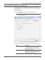
Part D301754X012 August 2015 Linear Meter Flow Calculation Program User Manual (for FloBoss™ 107) Remote Automation Solutions Linear Meter Flow Calculation Program User Manual Revision Tracking Sheet August 2015 This manual may be revised periodically to incorporate new or updated information. The revision date of each page appears at the bottom of the page opposite the page number. A change in revision date to any page also changes the date of the manual that appears on the front cover. Listed below is the revision date of each page (if applicable): Page All Pages Initial release ii Revision Aug-15 Jan-14 Revised Aug-15 Linear Meter Flow Calculation Program User Manual Contents Chapter 1 – Introduction 1.1 1.2 1.3 Scope and Organization...................................................................................................................... 1 Product Overview ................................................................................................................................ 1 Program Requirements ....................................................................................................................... 3 Chapter 2 – Installation 2.1 3.2 3.3 9 Linear Meter Setup Screen ............................................................................................................... 10 3.1.1 Linear Meter Setup Screen – General Tab .......................................................................... 12 3.1.2 Linear Meter Setup Screen – Inputs Tab ............................................................................. 16 3.1.3 Linear Meter Setup Screen – Advanced Tab ....................................................................... 19 3.1.4 Linear Meter Setup Screen – Fluid Properties Tab ............................................................. 22 3.1.5 Linear Meter Setup Screen – Sampler Tab ......................................................................... 25 3.1.6 Linear Meter Setup Screen – Calibration Factors Tab ........................................................ 27 3.1.7 Linear Meter Setup Screen – Alarms Tab............................................................................ 29 Linear Meter Values Screen.............................................................................................................. 32 3.2.1 Linear Meter Values –Values Tab........................................................................................ 34 3.2.2 Linear Meter Values Screen – Calculated Factors Tab ....................................................... 36 Saving the Configuration ................................................................................................................... 38 Chapter 4 – Reference 4.1 4.2 4.3 5 Downloading the Program................................................................................................................... 5 Chapter 3 – Configuration 3.1 1 40 Calculation Details ............................................................................................................................ 40 Point Type 31: Linear Meter Setup ................................................................................................... 42 Point Type 32: Linear Meter Values .................................................................................................. 44 Revised Aug-15 iii Linear Meter Flow Calculation Program User Manual [This page is intentionally left blank.] iv Revised Aug-15 Linear Meter Flow Calculation Program User Manual Chapter 1 – Introduction 1.1 Scope and Organization This document serves as the user manual for the Linear Meter Flow Calculation User Program (QER 08Q026), which is intended for use in a FloBoss™ 107 (FB107). This manual describes how to download and configure this program (referred to as the “Linear Meter program” or “the program” throughout the rest of this manual). Access and configure this program using ROCLINK™ 800 Configuration Software (version 1.80 or greater) loaded on an personal computer running Windows® 2000 (with Service Pack 2), Windows XP (with Service Pack 3), or Windows Vista™ (32-bit), or Windows 7 (32-bit and 64-bit). The sections in this manual provide information in a sequence appropriate for first-time users. Once you become familiar with the procedures and the software running in a FB107, the manual becomes a reference tool. This manual has the following major sections: Chapter 1 – Introduction Chapter 2 – Installation Chapter 3 – Configuration Chapter 4 – Reference This manual assumes that you are familiar with the FB107 and its configuration. For more information, refer to the following manuals: FloBoss 107 Flow Manager Instruction Manual (part D301232X012) ROCLINK 800 Configuration Software User Manual (for FB107) (part D301249X012) 1.2 Product Overview The Linear Meter program allows a FB107 to interface with meters whose flow input is proportional to either the mass flow or the uncorrected volumetric flow. Meter types with a flow input that is proportional to the uncorrected volumetric flow include turbine, vortex, ultrasonic, and positive displacement meters. Meter types with flow input that is proportional to the mass flow include Coriolis meters. Volume and mass flow rates and totals are calculated and stored for both volumetric and mass meters. The program uses the corresponding meter run point in the FB107’s firmware to store Linear Meter calculated values and accumulations. Additional configuration parameters are located in the program’s user-defined point types. Revised Aug-15 1 Linear Meter Flow Calculation Program User Manual For natural gas measurement with a turbine meter (per AGA Report #7 2006 edition), the Linear Meter program is NOT required, as this functionality for a volume type turbine meter for natural gas measurement is built into the FB107 firmware. However the program does provide an additional implementation of this calculation, and can be used in place of the firmware. You enable the Linear Meter calculation for meter runs with Linear Meter hardware installed. With the calculation enabled, the FB107 bypasses the standard meter run flow calculations and performs the Linear Meter calculation instead. All standard meter run parameters, as well as the additional Linear Meter parameters, are available for assignment to Modbus registers, PID control loops, historical archiving, and FST functions. The program is designed to integrate with the properties calculation included in the FB107 Firmware (AGA Report #8, 1992 edition for natural gas and other related hydrocarbons), or other fluids whose properties are provided by a separate user program installed in the FB107 (such as water and steam). The only fluid properties used by the Linear Meter program are the flowing and base densities. When correcting from volume at flowing conditions to volume at base conditions, the ratio of the flowing density to the base density is used. When a meter type of mass (Coriolis) is used, the program provides the ability to correct for the effect of pressure on the mass flowrate and accumulation. This feature is used for enhanced accuracy in high pressure Coriolis applications. This correction can be applied inside the Coriolis device itself, or within the FB107 Linear Meter program. However it is common to apply this correction in the FB107, as it is likely to contain the live value from a pressure transmitter. When used in conjunction with the FB107 Micro Motion Coriolis Interface Module, the program provides integration between the raw Coriolis data (without the use of pulses) and the FB107 meter runs. Linear Meter program accumulations are determined by detecting the incremental increases in the Coriolis Interface Module accumulator and adding that to the totals. Conversions between volume and mass units are handled automatically when the Coriolis Interface Module is used. 2 Revised Aug-15 Linear Meter Flow Calculation Program User Manual 1.3 Program Requirements You download the Linear Meter program to—and then run it from—the Flash and RAM memory on the FloBoss 107 with firmware version 1.40 (or greater). Download and configure the program using the ROCLINK 800 Configuration software version 2.30 (or greater). Notes: Two versions of the program for QER 08Q026 are included. Installation and operation are identical between the two programs, but they use different point type locations, different display numbers, and are loaded into different program slots on the FB107. LinearMeter_5.bin loads into user program location 5 and User Defined Points (UDP) 31 and 32. LinearMeter_6.bin loads into user program location 6 and User Defined Points (UDP) 33 and 34. Install the program version that avoids point type conflicts with currently installed programs. This document shows the installation of LinearMeter_5.bin. The installation process and functionality is the same for all version of the Linear Meter Flow Calculation Program. The downloadable program is: File Name Target Unit/ Version User Defined Point (UDP) Flash Used (in bytes) DRAM Used (in bytes) ROCKLINK 800 Version Display Number LinearMeter_5.bin 1.04 31, 32 13297 16,384 2.30 32, 33 LinearMeter_6.bin 1.04 33, 34 13297 16,384 2.30 34, 35 Note: You must connect a PC to the FloBoss’s LOI port before starting the download. For information on viewing the memory allocation of user programs, refer to the ROCLINK 800 Configuration Software User Manual (for FB107) (part D301249X012). Revised Aug-15 3 Linear Meter Flow Calculation Program User Manual [This page is intentionally left blank.] 4 Revised Aug-15 Linear Meter Flow Calculation Program User Manual Chapter 2 – Installation This section provides instructions for installing the Linear Meter program into the FB107. Read Section 1.3 of this manual for program requirements. 2.1 Downloading the Program This section provides instructions for installing the user program into FloBoss memory. Note: Connect a PC to the FloBoss’s LOI port before starting the download. To download the user program: 1. Start and logon to ROCLINK 800. 2. Select ROC > Direct Connect to connect to the FloBoss unit. 3. Select Utilities > User Program Administrator from the ROCLINK menu bar. The User Program Administrator screen displays (see Figure 1): Figure 1. User Program Administrator 4. Click Browse in the Download User Program File frame. The Select User Program File screen displays (see Figure 2). 5. Select the path and user program file to download from the CD-ROM. (Program files are typically located in the Program Files folder on the CD-ROM). As Figure 2 shows, the screen lists all valid user program files with the .BIN extension: Revised Aug-15 5 Linear Meter Flow Calculation Program User Manual Figure 2. Select User Program File 6. Click Open to select the program file. The User Program Administrator screen displays. As shown in Figure 3, note that the Download User Program File frame identifies the selected program and that the Download & Start button is active: Figure 3. User Program Administrator 6 Revised Aug-15 Linear Meter Flow Calculation Program User Manual 7. Click Download & Start to begin loading the selected programs. The following message displays: Figure 4. Confirm Download Note: For the FB107, ROCLINK800 assigns program positions based on memory allocations. For this reason, the LinearMeter_5.bin program automatically installs as program 5. For LinearMeter_6.bin program automatically installs as program 6. 8. Click Yes to begin the download. During the download, the program performs a warm start, creates an event in the event log, and—when the download completes—displays the following message: Figure 5. ROCLINK 800 Download Confirmation 9. Click OK. The User Program Administrator screen displays (see Figure 6). Note that: The User Programs Installed in Device frame identifies the loaded program. The Status field indicates that the program is running. Revised Aug-15 7 Linear Meter Flow Calculation Program User Manual Figure 6. User Program Administrator 10. Click Close and proceed to Chapter 3 to configure the program. 8 Revised Aug-15 Linear Meter Flow Calculation Program User Manual Chapter 3 – Configuration After you have downloaded and started the Linear Meter program, you configure the program and view calculation results using the ROCLINK 800 software. To do this, you use two program-specific screens (Linear Meter Setup and Linear Meter Values): Use the Linear Meter Setup screen to set the parameters for the meter run. Use the Linear Meter Values screen to view results from the Linear Meter calculations. Note: Configure history points after you configure the Linear Meter program. To configure history points, refer to Table 7-2. EFM History Points (AGA 7) in Section 10.2 of the ROCLINK800 Configuration Software User Manual (for FloBoss 107), (part D301249X012). Figure 7. ROCLINK 800 Revised Aug-15 9 Linear Meter Flow Calculation Program User Manual 3.1 Linear Meter Setup Screen Once you have successfully loaded the Linear Meter program into the FloBoss, you can access the Linear Meter Setup screen and configure the meter runs. To access this screen: 1. Click User Program > Linear Meter > Display #32, Linear Meter Setup from the ROCLINK configuration tree: 2. Double-click #1, Meter #1. The Linear Meter screen displays (see Figure 8): Figure 8. Linear Meter Setup Note: Six fields at the top of the screen (Point number, Program Status, Meter Tag, Meter Description, Active Calculations – Flow, and Active Calculations – Fluid Props) appear on all tabs. 10 Revised Aug-15 Linear Meter Flow Calculation Program User Manual 3. Review and change as necessary the values in the following fields: Field Description Point Number Selects the meter run to configure. Click to display all defined instances. Clicking a different meter run causes the screen to display the values for that meter run. Program Status This read-only field shows the current state of the user program. Valid values are: Program Not Loaded, Program Loaded – Not Started, Program Running, Program Shutting Down, and Not Running – Library Version Error. Meter Tag Sets the unique identifier for the selected meter. Meter Description Sets the description of the selected meter. Flow This read-only field shows the flow calculation standard currently performing flow calculations for the selected meter run. Fluid Props This read-only field shows the properties calculation standard currently performing properties calculations for the selected meter run. 4. Click Apply to save your changes, and proceed to Section 3.1.1 to configure the General tab. Revised Aug-15 11 Linear Meter Flow Calculation Program User Manual 3.1.1 Linear Meter Setup Screen – General Tab Use the General tab (which displays when you access the Linear Meter Setup screen) to enable the Linear Meter calculation, specify the averaging technique used by the program, and define program-specific options. Figure 9. Linear Meter, General Tab 1. Review and change as necessary the values in the following fields: Field Description Linear Meter Enables or disables the Linear Meter program to perform the flow calculations for the selected meter run. Valid selections are Enabled or Disabled. Sets the type of meter associated with the meter run. Valid selections are Volume (volume metering device such as a turbine meter) or Mass (Micro Motion Coriolis Mass Meter or similar mass meter). Note: This field displays only if you select Enabled for the Linear Meter option. Meter Type Units for Heating Value, Alarms, and Sampler 12 Sets the type of units used for heating value, alarms, and sampler of the meter run. Valid selections are Volume, (units are BTU/CF or MJ/M3, Ft3 or M3, etc) and Mass (units are BTU/Lb or MJ/Kg, Lb or Kg, etc). Revised Aug-15 Linear Meter Flow Calculation Program User Manual Field Flow Alarming Base Multiplier Value (BMV) Integral Multiplier Value (IMV) Averaging Technique Description Enables or disables flow alarming for the meter. If enabled, alarm status changes are added to the Alarm Log. Use the Alarms tab to configure the alarms. If disabled, no alarm generates for this meter, regardless of the alarm configuration. Sets, in minutes, how frequently the system recalculates the fluid properties and resulting Base Multiplier Value (BMV) (per the API measurement standard Chapter 21, Section 1). If the flow calculation for the meter run is AGA392, ISO5167-2003, or another calculation standard where the flow input is a differential pressure, this field is labeled Integral Multiplier Value (IMV). Sets the averaging technique for determining the average static pressure and flowing temperature during each BMV/IMV for the meter run. If the flow input is from a differential pressure meter, the average differential pressure is also determined. For further details, see API measurement standard Chapter 21, Section 1, Appendix B. Valid selections are: Flow Dependant Linear Revised Aug-15 Calculates the average static pressure and average flowing temperature with equal weighting given to each sample when there is flow through the meter. For samples in which there is no flow, the value is not included in the average. However, if there is no flow during the BMV/IMV, the system determines averages using all of the samples. 13 Linear Meter Flow Calculation Program User Manual Field Description Calculates averages for the static Flow Dependant pressure and flowing temperature Formulaic where each sample is raised to the power to which the parameter is raised in the flow equation, with equal weighting given to each sample when there is flow through meter. For samples where there is no flow, the value is not included in the averaging. However, if there is no flow during the BMV/IMV, averages are determined using all of the samples. At the end of the BMV/IMV, the resulting average is raised to the reciprocal of the power to which the value is raised in the flow equation. Note: Flow Dependent Linear and Flow Dependent Formulaic averaging yield the same result when used with linear meters. Flow Weighted Linear 14 Calculates averages for the static pressure and flowing temperature with weighting for a sample being the ratio of the flow through the meter at the time of the sample to the total flow during the BMV/IMV. For samples where there is no flow, the value is not included in the average. However, if there is no flow during the BMV/IMV, averages are determined using all of the samples. Revised Aug-15 Linear Meter Flow Calculation Program User Manual Field Description Calculates averages for the static Flow pressure and flowing temperature Weighted Formulaic where each sample is raised to the power to which the parameter is raised in the flow equation, with weighting for a sample being the ratio of the flow at the time of the sample to the total flow during the BMV/IMV. For samples where there is no flow, the value is not included in the average. However, if there is no flow during the BMV/IMV, averages are determined using all of the samples. At the end of the BMV/IMV, the resulting average is raised to the reciprocal of the power to which the value is raised in the flow equation. With a linear meter, flow weighted formulaic averaging yields the same result as flow weighted linear averaging. Note: Flow Weighted Linear and Flow Weighted Formulaic averaging yield the same result when used with linear meters. Active Flow Alarms This display-only field shows any alarm currently active. For example, Low indicates that the calculated flow is below the Low Alarm limit. Other alarms can include High, No Flow, and Manual Mode. 2. Click Apply to save any changes, and proceed to Section 3.1.2 to configure the Inputs tab. Revised Aug-15 15 Linear Meter Flow Calculation Program User Manual 3.1.2 Linear Meter Setup Screen – Inputs Tab Use the Inputs tab to define the inputs used by the Linear Meter calculation. To access this screen: 1. Select the Inputs tab on the Linear Meter Setup screen. One of the following four screens displays: Note: This tab displays only if you select Enabled for Linear Meters on the General tab. 16 Figure 10(a). Linear Meter Setup, Inputs tab (Meter Type is Volume, I/O Definition is a PI Point) Figure 10(b). Linear Meter Setup, Inputs tab (Meter Type is Volume, I/O Definition is an Analog Value) Figure 10(c). Linear Meter Setup, Inputs tab (Meter Type is Mass, I/O Definition is a PI Point) Figure 10(d). Linear Meter Setup, Inputs tab (Meter Type is Mass, I/O Definition is an Analog Value) Revised Aug-15 Linear Meter Flow Calculation Program User Manual 2. Review and change as necessary the values in the following fields: Field Uncorrected Volume Revised Aug-15 Description Sets the parameter for the uncorrected volume flow rate from the meter. Click to display the Select TLP dialog box you use to assign the parameter. The units for the uncorrected volume value are MCF/Day or kM3/Day. If the parameter for the uncorrected volume flow rate is from a PI point, select parameter 13 (EU). If the parameter for the uncorrected volume flow rate is an analog value, select that parameter. Note: This field displays only if the meter type is volume. Mass Sets the parameter for the mass flow rate from the meter. Click to display the Select TLP dialog box you use to assign the parameter. The units of the mass are Mlb/Day or Tonnes/Day. If the parameter for the mass flow rate is from a PI point, select parameter 13 (EU). If the parameter for the mass is an analog value, select that parameter. Note: This field displays only if the meter type is mass (Coriolis). When the program is used with the Micro Motion Coriolis Interface Module, this should be set to the module's forward mass flow rate, parameter 11 (Mass Flow Rate Fwd" of point type 65. Static Pressure Sets the parameter for the static pressure. Click to display the Select TLP dialog box you use to assign the parameter. The units for the static pressure are PSIG/PSIA or kPa(g)/kPa(a). Temperature Sets the parameter for the flowing temperature of the fluid. Click to display the Select TLP dialog box you use to assign the parameter. The units for the flowing temperature are Deg F or Deg C. Accumulator Sets the parameter for an accumulator containing the current amount of flow measured by the meter. It is assumed that this parameter rolls over at 1,000,000.0 and is in the appropriate units. When the program is used in conjunction with the Micro Motion Coriolis Interface Module, this should be set to the module’s ongoing mass accumulator, parameter 171 (Mass Accumulated) of point type 65. The program will automatically convert the mass to the required units in this case. 17 Linear Meter Flow Calculation Program User Manual Field Description No Flow Time Sets the amount of time without a pulse, in seconds, before the no flow status is set. Note: This field displays only if the I/O Definition for the flow rate parameter is a PI point. Low Flow Cutoff Sets the low flow cutoff point. When the value of the flow input parameter is less than or equal to this value, the calculated flow rate is set to zero and, if alarming is enabled, the No Flow alarm status is set and an entry is made in the Alarm Log. The units of the low flow cutoff are MCF/Day or kM3/Day. Note: This field displays only if the I/O Definition for the flow rate parameter is an analog value. Static K Factor Sets the K factor when the variable K factor is disabled or the I/O definition for the flow rate parameter is an analog value. If the flow rate parameter is an analog value, pulses are generated from the analog value and added to the total pulses stored in parameter 59 of point type 47. If the variable K factor is enabled, the static K factor is the last K factor calculated from the variable K factor table. The K factor is the number of pulses per unit of flow. The units are pulses/Cf, pulses/M3, pulses/Lb, or pulses/Kg. Variable K Factors Enables the use of the variable K Factor table and sets the K Factor values over a range of pulse frequencies. The units of the values of the K Factor are pulses/Cf, pulses/M3, pulses/Lb, or pulses/Kg. The units of the pulse frequencies are Hz. If this field is Disabled, the Static K Factor is used. Note: These fields displays only if the I/O Definition for the flow rate parameter is a PI point. 3. Click Apply to save any changes, and proceed to Section 3.1.3 to configure the Advanced tab. 18 Revised Aug-15 Linear Meter Flow Calculation Program User Manual 3.1.3 Linear Meter Setup Screen – Advanced Tab Use the Advanced tab to define additional meter run information for the Linear Meter flow calculation. To access this screen: 1. Select the Advanced tab on the Linear Meter Setup screen. One of the following two screens displays: Note: This tab displays only if you select Enabled for Linear Meters on the General tab. Figure 11(a). Linear Meter Setup, Advanced tab (Meter Type is Volume) Figure 11(b). Linear Meter Setup, Advanced tab (Meter Type is Mass) 2. Review and change as necessary the values in the following fields: Revised Aug-15 Field Description Atmospheric Pressure Sets how the program determines atmospheric pressure (absolute) at the metering location. Valid selections are Calculate (calculate atmospheric pressure from other parameters defined on this screen) or Enter (use the value, either as PSIA or kPa(a), entered in the field in this frame). The default is Enter. Note: If you select Enter, the value must be greater than zero. 19 Linear Meter Flow Calculation Program User Manual 20 Field Description Gravitational Acceleration Sets how the program determines gravitational acceleration at the metering location. Valid selections are Calculate (calculate gravitational acceleration from other parameters defined on this screen) or Enter (use the value, either as Ft/Sec2 or M/Sec2, entered in the field in this frame). The default is Calculate. Note: If you select Enter, the value must be greater than zero. Base Pressure Sets, in PSIA or kPa(a), the flow measurement base pressure specified in the gas contract. Base Temperature Sets, in degrees Fahrenheit or degrees Celsius, the flow measurement base temperature specified in the gas contract. Elevation Sets, in feet or meters above sea level, the elevation of the metering location. Latitude Sets, in degrees, the latitude of the metering location. Correction for Pressure Effect on Mass Flow Accuracy Enables or disables the correction of the mass flow input due to pressure effects. Note: This field displays only if the meter type is mass (Coriolis). Calibration Pressure Sets the calibration pressure of the mass flow meter for determining the pressure effect correction of the mass flow input. Units are PSIG or kPa(g). Note: This field displays only if the meter type is mass (Coriolis). Pressure Effect Sets the coefficient for the effect of pressure on the mass flow accuracy. Units are %/PSI or %/kPa. Note: The flow computer implementation of the correction for pressure effect on mass flow accuracy requires the Pressure Effect to be entered as a negative number as indicated in the sensor product data sheet. Force Recalculation Forces the program to recalculate the flow without waiting for the next normal recalculation. Select Set and click Apply to force the recalculation. Note: You define normal recalculation periods using the Base Multiplier Period field (located on the Linear Meter Setup screen’s General tab). Limit Meter Events Sets whether the FB107 logs all flow-related events. Valid selections are Enabled (log all events) or Disabled (do not log events). Revised Aug-15 Linear Meter Flow Calculation Program User Manual Field Pressure Tap Description Sets the reference of the static pressure. This field must match how the sensor or transmitter actually measures the static pressure. Valid selections are Gauge and Absolute. 3. Click Apply to save any changes, and proceed to Section 3.1.4 to configure the Fluid Properties tab. Revised Aug-15 21 Linear Meter Flow Calculation Program User Manual 3.1.4 Linear Meter Setup Screen – Fluid Properties Tab Use the Fluid Properties tab to define the fluid composition and other properties. To access this screen: 1. Select the Fluid Properties tab on the Linear Meter Setup screen. Note: This tab displays only if you select Enabled for Linear Meters on the General tab. Figure 12. Linear Meter Setup, Fluid Properties tab 2. Review and change as necessary the values in the following fields: Field Composition FPV Method 22 Description Sets the mole percent for each gas component. If the FPV Method is Detailed, the value in the Total Mole % field must equal 100%. If the FPV Method is Gross1, only the mole % of CO2 must be entered. If the FPV Method is Gross2, the mole % of CO2 and the mole % of N2 must be entered. Sets the method of determining the compressibility factors for AGA8 calculations. Valid selections are: Revised Aug-15 Linear Meter Flow Calculation Program User Manual Field Description Detailed Requires the natural gas composition in mole percent to be entered for all components. Gross1 Requires the specific gravity of the natural gas, the real gas gross heating value per unit volume, and the mole % of CO2 to be entered. Gross2 Requires the specific gravity of the natural gas, the mole % of CO2, and the mole % of N2 to be entered. Note: If you choose either Gross1 or Gross2, you must manually enter values for Specific Gravity and Heating Value on this screen. Gross2 only requires a value for Heating Value if you’re calculating the gas energy flow. While the Detailed method provides the highest accuracy in a broad range of measurement conditions, you can use either of the Gross methods when: Temperature is between 32°F and 130°F (0°C and 54°C). Pressure is between 0 and 1200 PSIA (0 and 8274 kPa(a)). Gas composition is within the Normal range, as defined in the 1992 AGA8 report. Heating Value Sets how the system determines the heating value of the gas. Valid selections are Calculate (allow the system to calculate the heating value from the gas composition data) or Enter (use the value specified in the energy calculation). Note: Set the Units for Heating Value, Alarms, and Sampler parameter on the General tab to select volume or mass measurement in English units (BTU/CF or BTU/Lb) or metric units (MJ/M3 or MJ/Kg). Heating Value Basis Identifies the basis the system uses to determine the heating value for flow or energy calculations. Valid selections are: Dry Revised Aug-15 No water vapor present in gas. 23 Linear Meter Flow Calculation Program User Manual Field Description Wet As Delivered Saturated water vapor present in gas. Note: When you select this option, the FB107 calculates the mole percentage of water based on the algorithm from IAPWS—IF97 standards and adjusts the other mole percentages accordingly. Gas may contain some water vapor. Specific Gravity Sets the ratio of the molar mass of the gas to the molar mass of the air. Valid selections are Calculate (the system calculates the value) and Enter (use the specific value for the flow calculation). Note: If you select Enter, the value should represent the gas at standard conditions and cannot be less that 0.07. Viscosity Sets the dynamic viscosity of the flowing gas. Units are Lbm/Ft-Sec (English units) or cP (metric units). Sp Heat Ratio Sets the specific heat ratio of the gas (defined as the specific heat of the gas at constant pressure divided by the specific heat of the gas at constant volume). Accepted practice for natural gas applications is to use a value of 1.3, which was used to develop the expansion factor tables in the AGA 3 Report – Part 3. If entered, the value must be greater than zero. Gas Quality Sets the source for the gas compositions and other properties. Valid selections are Constant (readings are manually entered and changes are added to the event log) or Live (readings come from a gas chromatograph or are periodically downloaded from a host and changes are not added to the event log). Log Methane Adjust Sets if system adjustments to the methane composition are added to the event log. Valid selections are Enabled (adjustments are added to the event log) or Disabled (adjustments are not added to the event log). 3. Click Apply to save any changes, and proceed to Section 3.1.5 to configure the Sampler tab. 24 Revised Aug-15 Linear Meter Flow Calculation Program User Manual 3.1.5 Linear Meter Setup Screen – Sampler Tab Use the Sampler tab to set up the discrete output (DO) to send a pulse output to another device, such as an odorizer, or to control a gas sampler for a meter run. To access this screen: 1. Select the Sampler tab on the Linear Meter Setup screen. Note: This tab displays only if you select Enabled for Linear Meters on the General tab. Figure 13. Linear Meter Setup, Sampler tab 2. Review and change as necessary the values in the following fields: Field Sampler Control Output Point Revised Aug-15 Description Enables sampling for the meter run. When enabled, the Output Point is set when the previous flow matches or exceeds the value in the Sampler Accum field. Sets the parameter for the output to drive the sampler. Click to display the Select TLP dialog you use to define the parameter. It must be parameter 3 of a DO point. 25 Linear Meter Flow Calculation Program User Manual Field Sampler Accum Sampler Duration Description Sets the quantity of fluid that must pass before the status of the Output Point is set. Units are Cf, M3, Lb, or Kg based on the Units Type for Heating Value, Alarms, and Sampler on the General tab. Sets the duration, in seconds, for holding the status of the Output Point to ON when the quantity of fluid passed matches or exceeds the Sampler Accum. 3. Click Apply to save any changes, and proceed to Section 3.1.6 to configure the Calibration Factors tab. 26 Revised Aug-15 Linear Meter Flow Calculation Program User Manual 3.1.6 Linear Meter Setup Screen – Calibration Factors Tab Use the Calibration Factors tab to define information related to pressure calibration. To access this screen: 1. Select the Calibration Factors tab on the Linear Meter Setup screen. Note: This tab displays only if you select Enabled for Linear Meter on the General tab. Figure 14. Linear Meter Setup, Calibration Factor tab 2. Review and change as necessary the values in the following fields: Revised Aug-15 Field Dead Weight Calibration: Static Pressure Description Sets if the program compensates the static pressure value for the difference between the gravitational acceleration at the location where the static pressure was calibrated and the gravitational acceleration associated with the dead weight calibrator. Calibrated Gravitational Acceleration Sets the gravitational acceleration associated with the dead weight calibrator. The units are Ft/Sec2 or M/Sec2. 27 Linear Meter Flow Calculation Program User Manual Field User Correction Factor Description Sets a multiplier value to adjust the flow for factors not included with the Linear Meter program. Note: Use the default value of 1.0 if no correction is desired. 3. Click Apply to save any changes, and proceed to Section 3.1.7 to configure the Alarms tab. 28 Revised Aug-15 Linear Meter Flow Calculation Program User Manual 3.1.7 Linear Meter Setup Screen – Alarms Tab Use the Alarms tab to define information related to flow alarming. To access this screen: 1. Select the Alarms tab on the Linear Meter Setup screen. Note: This tab displays only if you select Enabled for Linear Meter on the General tab. Figure 15. Linear Meter Setup, Alarms tab 2. Review and change as necessary the values in the following fields: Field Time Basis for Alarming Revised Aug-15 Description Sets the parameter whose value is to be used for alarming. If Alarm on Daily Flow Rate is selected, the daily volume or mass flow rate is used for alarming. If Alarm on Hourly Flow Rate is selected, the hourly volume or mass flow rate is used for alarming. The use of the volume or mass flow rate is dependent on the Units Type for Heating Value, Alarms, and Sampler on the General tab. 29 Linear Meter Flow Calculation Program User Manual Field Low Alarm Limit High Alarm Limit Description Sets the value below which the calculated flow rate must fall to generate a low alarm. The units are MCF/Day, CF/Hour, Mlb/Day, Lb/Hour, kM3/Day, M3/Hour, Tonnes/Day, or Kg/Hour. Note: Default value is 0.0 Mlb/Day if you select Mass for Units for Heating Value, Alarms and Sampler on the General tab and 0.0 MCF/Day if you select Volume for Units for Heating Value, Alarms and Sampler on the General tab. Sets the value above which the calculated flow rate must rise to generate a high alarm. The units are MCF/Day, CF/Hour, Mlb/Day, Lb/Hour, kM3/Day, M3/Hour, Tonnes/Day, or Kg/Hour. Note: Default value is 10,000 Mlb/Day if you select Mass for Units for Heating Value, Alarms and Sampler on the General tab and 10,000 MCF/Day if you select Volume for Units for Heating Value, Alarms and Sampler on the General tab. Alarm Deadband Sets a value that defines a zone above the Low Alarm limit and below the High Alarm limit. When an alarm condition is set, the flow rate must clear the alarm limit plus the zone defined by the deadband, before the alarm condition clears. This deadband prevents the system from setting and clearing the alarm continuously when the input value is oscillating around the alarm limit. The units are MCF/Day, CF/Hour, Mlb/Day, Lb/Hour, kM3/Day, M3/Hour, Tonnes/Day, or Kg/Hour. Note: Default value is 0.0 Mlb/Day if you select Mass for Units for Heating Value, Alarms and Sampler on the General tab and 0.0 MCF/Day if you select Volume for Units for Heating Value, Alarms and Sampler on the General tab. RBX Alarming 30 Sets alarming options for initiating Report-byException messages. These messages are sent out through communication ports that have RBX mode enabled. Disabled RBX Alarming is turned off. On Alarm Set When the point enters an alarm condition, the FB107 generates a Report-by-Exception message to the host. On Alarm Clear When the point leaves an alarm condition, the FB107 generates a Report-by-Exception message to the host. Revised Aug-15 Linear Meter Flow Calculation Program User Manual Field Description On Alarm Set and Clear In either condition, an RBX message generates to the host. 3. Click Apply to save any changes. 4. Click Close to close this screen, and proceed to Section 3.2 to configure the Linear Meter Values screen. Revised Aug-15 31 Linear Meter Flow Calculation Program User Manual 3.2 Linear Meter Values Screen Use this screen to view the results and calculation factors used in Linear Meter calculations To access this screen: 1. Click User Program > Linear Meter > Display #33, Linear Meter Values from the ROCLINK configuration tree: 2. Double-click #1, Meter #1. The Linear Meter Values screen displays: Figure 16. Linear Meter Values Note: Six fields at the top of the screen (Point number, Program Status, Meter Tag, Meter Description, Active Calculations – Flow, and Active Calculations – Fluid Props) appear on all tabs. 3. Review and change as necessary the values in the following fields: 32 Field Description Point Number Selects the meter run to configure. Click to display all defined instances. Clicking a different meter run causes the screen to display the values for that meter run. Program Status This read-only field shows the current state of the user program. Valid values are: Program Not Loaded, Program Loaded – Not Started, Program Running, Program Shutting Down, and Not Running – Library Version Error. Meter Tag This read-only field shows the unique identifier for the selected meter. Revised Aug-15 Linear Meter Flow Calculation Program User Manual Field Description Meter Description This read-only field shows the description of the selected meter. Active Calculations: Flow This read-only field shows the flow calculation standard currently performing flow calculations for the selected meter run. Active Calculations: Fluid Props This read-only field shows the properties calculation standard currently performing properties calculations for the selected meter run. 4. Click Apply to save any changes, and proceed to Section 3.2.1 to configure the Values tab. Revised Aug-15 33 Linear Meter Flow Calculation Program User Manual 3.2.1 Linear Meter Values –Values Tab Use the Values tab (which displays one of the following three screens when you access the Linear Meter Values screen) to view results of the Linear Meter calculations. Figure 17(a). Linear Meter Values,Values tab (Meter Type is Volume) Figure 17(b). Linear Meter Values, Values tab (Meter Type is Mass) 1. Review the values in the following fields: 34 Field Description Uncorrected Volume This read-only field displays uncorrected volume flow rate, which is the volumetric flow input before any density correction is applied. The units are MCF/Day or kM3/Day. Note: This field displays only if you select Volume for meter type on the General tab of the Linear Meter Setup screen. Uncompensated Mass This read-only field displays uncompensated mass flow rate, which is the mass flow input before pressure compensation is applied. The units are Mlb/Day or Tonnes/Day. Note: This field displays only if you select Mass (Coriolis) for meter type on the General tab of the Linear Meter Setup screen. Static Pressure This read-only field displays current static pressure in PSIG, PSIA, kPa(g) or kPa(a). Flowing Temperature This read-only field displays current flowing temperature in Deg F or Deg C. Current Accumulator Value If an accumulator type meter is in use, this read-only field displays the value of the accumulator read during the current second. Revised Aug-15 Linear Meter Flow Calculation Program User Manual Field Description Previous Accumulator Value If an accumulator type meter is in use, this read-only field displays the value of the accumulator read during the previous second. Current Flow Rate – Volume This read-only field displays current hourly and daily flow rates in CF/Hour and MCF/Day or M3/hr and kM3/Day. Current Flow Rate – Energy This read-only field displays current hourly and daily energy rates in BTU/Hour and MMBTU/Day or MJ/Hour and GJ/Day. Current Flow Rate – Mass This read-only field displays current hourly and daily mass rates in Lb/Hour and Mlb/Day or Kg/Hour and Tonnes/Day. Accumulation – Uncorrected This read-only field displays uncorrected volume total flow in MCF or Km3 for the current day, the previous day, the current month, the previous month, and the accumulated total since the accumulator last reset. Accumulation – MCF This read-only field displays total flow in MCF or kM3 for the current day, the previous day, the current month, the previous month, and the accumulated total since the accumulator last reset. Accumulation –MMBTU This read-only field displays total energy in MMBTU or GJoules for the current day, the previous day, the current month, the previous month, and the accumulated total since the accumulator last reset. Accumulation – Mlb This read-only field displays total mass in Mlb or Tonnes for the current day, the previous day, the current month, the previous month, and the accumulated total since the accumulator last reset. Accumulation – Minutes This read-only field displays flowing time in Minutes for the current day, the previous day, the current month, the previous month, and the accumulated total since the accumulator last reset. 2. Click Apply to save any changes and proceed to Section 3.2.2 to configure the Calculated Factors tab. Revised Aug-15 35 Linear Meter Flow Calculation Program User Manual 3.2.2 Linear Meter Values Screen – Calculated Factors Tab Use this tab to view calculation factors used in Linear Meter calculations. To access this screen: 1. Select the Factors tab on the Linear Meter Values screen. One of the following two screens displays: Note: This tab displays only if you select Enabled for the Linear Meter on the General tab of the Linear Meter Setup screen. Figure 18(a). Linear Meter Values,Values tab (Meter Type is Volume) Figure 18(b). Linear Meter Values, Values tab (Meter Type is Mass) 2. Review the values in the following fields: 36 Field Description Uncorrected Volume This read-only field displays the uncorrected volume flow rate, which is the volumetric flow input before any density correction is applied. The units are MCF/Day or kM3/Day. Note: This field displays only if you select Volume for meter type on the General tab of the Linear Meter Setup screen. Uncompensated Mass This read-only field displays the uncompensated mass flow rate, which is the mass flow input before the correction for pressure effect is applied. The units are Mlb/Day or Tonnes/Day. Note: This field displays only if you select Mass (Coriolis) for meter type on the General tab of the Linear Meter Setup screen. Flowing Density This read-only field shows the calculated density at flowing conditions in Lb/CF or Kg/M3. Revised Aug-15 Linear Meter Flow Calculation Program User Manual Field Description Base Density This read-only field shows the calculated density at base conditions in Lb/CF or Kg/M3. BMV This read-only field displays the base multiplier value (BMV), which is the factor for multiplying by the uncorrected volume flow rate to determine the corrected volume flow rate. Note: This field displays only if you select Volume for meter type on the General tab of the Linear Meter Setup screen. Pressure Effect Correction Factor This read-only field displays the pressure effect correction factor, which is calculated from the pressure effect coefficient and the difference between the flowing and calibration pressures. Note: This field displays only if you select Mass (Coriolis) for meter type on the General tab of the Linear Meter Setup 3. Click Apply to save any changes. 4. Click Close to close this screen. Proceed to Section 3.3 to save your configuration. Revised Aug-15 37 Linear Meter Flow Calculation Program User Manual 3.3 Saving the Configuration Whenever you modify or change the configuration, it is a good practice to save the final configuration to memory. To save the configuration: 1. Select ROC > Flags. The Flags screen displays: Figure 19. Flags 2. Click Save Configuration. A verification message displays: Figure 20. Save Verification 38 Revised Aug-15 Linear Meter Flow Calculation Program User Manual 3. Click Yes. When the save process completes, a confirmation message displays: Figure 21. Confirmation Note: Depending on the size and complexity of the user program, this process may take several minutes. When the process ends, the Status field on the Flags screen displays Completed. Figure 22. Flags, Status - Completed 4. Click Update on the Flags screen. This completes the process of saving your new configuration. Note: For archive purposes, you should also save this configuration to your PC’s hard drive or a removable media (such as a flash drive) using the File > Save Configuration option on the ROCLINK 800 menu bar. Revised Aug-15 39 Linear Meter Flow Calculation Program User Manual Chapter 4 – Reference This section provides calculation details and tables of information on the user defined points used by the Linear Meter Flow Calculation program. Calculation Details Point Type 31: Linear Meter Setup Point Type 32: Linear Meter Values 4.1 Calculation Details The Linear Meter flow calculations are based on equations presented in the following flow calculation standards. Measurement of Gas by Turbine Meters, Transmission Measurement Committee Report No. 7, American Gas Association (AGA), Second Revision, April, 1996. Measurement of Natural Gas by Coriolis Meter, AGA Report No. 11, API MPMS 14.9, Transmission Measurement Committee,, American Gas Association (AGA), 2003. Each of these flow calculation standards can be implemented using the Linear Meter program. However, AGA7 is already available with the FB107 Application Firmware, so it is recommended to use that implementation for meter runs requiring AGA7. If you specify Volume as meter type, the flow calculations are: Qb = Qf * ρf / ρb qm = Qb * ρb where: 40 Qb = Volumetric flow at base conditions. Units are MCF or kM3. Qf = Volumetric flow at flowing conditions (uncorrected flow). Units are MCF or kM3. qm = Mass flow. Units are Mlb or Tonnes. ρb = Density at base conditions. Units are Lb/CF or Kg/M3. ρf = Density at flowing conditions. Units are Lb/CF or Kg/M3. Revised Aug-15 Linear Meter Flow Calculation Program User Manual If you specify Mass (Coriolis) as meter type, the flow calculations are: qm = qm,u * FP Qb = qm / ρb where: FP = Correction for pressure effect on the mass flow accuracy. Qb = Volumetric flow at base conditions. Units are MCF or kM3. qm = Mass flow. Units are Mlb or Tonnes. qm,u = Mass flow before correction for pressure effect. Units are Mlb or Tonnes. ρb = Density at base conditions. Units are Lb/CF or Kg/M3. If correction for pressure effect is enabled: FP = 1.0 / (1.0 + (KP / 100.0) * (Pf – Pc)) where: KP = Pressure effect coefficient. Units are %/PSIG or %/kPa(g). Pf = Calibration pressure. Units are PSIG or kPa(g) Pc = Flowing pressure. Units are PSIG or kPa(g) If correction for pressure effect is disabled: FP = 1.0 With both volume and mass meters, the program updates flow inputs once a second and calculates approximations of the flow rates and totals. The program revises approximated flow totals at the specified base multiplier period (BMP) using the total of flow input, base density, and average flowing density (recalculated using the average pressure and temperature during the BMP). Revised Aug-15 41 Linear Meter Flow Calculation Program User Manual 4.2 Point Type 31: Linear Meter Setup Point type 31 contains the parameters for configuring the Linear Meter program. There are four logicals of this point type (one logical for each meter run). Point Type 31: Linear Meter Setup Parm # Name Access Data Type Length Range Default Description of functionality and meaning of values 0 Point Tag ID R/O AC 10 0x20 -> 0x7E for Each ASCII character ““ Point tag identification. This value is copied from point type 46, parameter 0. 1 Enable Linear Meter R/W UINT8 1 0 -> 1 0 Enable/disable status of the linear meter flow calculation for the meter run. Valid values are: 0 = Disable 1 = Enable 2 Meter Type R/W UINT8 1 0 -> 1 0 Type of meter. Valid values are: 0 = Volume – The flow input is proportional to the uncorrected volumetric flow. 1 = Mass (Coriolis) – The flow input is proportional to the mass flow. 3 Press Effect Enable R/W UINT8 1 0 -> 1 0 If the meter type is volume: Not used. If the meter type is mass (Coriolis): Enable/disable the correction for the pressure effect on the mass flow accuracy. Valid values are: 0 = Disable 1 = Enable Revised Aug-15 42 Linear Meter Flow Calculation Program User Manual Point Type 31: Linear Meter Setup Parm # Name Access Data Type Length Range Default 4 Calibration Pressure R/W FL 4 Any floating point number 0.0 If the meter type is volume: Not used. If the meter type is mass: Calibration pressure of the mass meter from which the correction for the pressure effect on the mass flow accuracy is determined. Units are PSIG or kPa(g). 5 Press Effect Coeff R/W FL 4 Any floating point number 0.0 If the meter type is volume: Not used. If the meter type is mass: Pressure effect coefficient for the mass meter. Units are %/PSIG or %/kPa(g). The correction for pressure effect on mass flow accuracy requires the pressure effect coefficient to be a negative number as indicated in the sensor product data sheet. 6 Accumulator TLP R/W TLP 3 Any valid TLP 0,0,0 Revised Aug-15 Description of functionality and meaning of values Accumulator Input for this program. Configuring this parameter triggers the Linear Meter program to read the parameter specified by Accumulator TLP and use its value, along with the specified rate, to calculate accumulated totals. NOTE: The Linear Meter Program assumes that the accumulator is in the correct units for the meter run in which it is used. 43 Linear Meter Flow Calculation Program User Manual 4.3 Point Type 32: Linear Meter Values Point type 32 contains the calculated parameters for the Linear Meter program. There are four logicals of this point type (one logical for each meter run). Point Type 31: Linear Meter Setup 44 Parm # Name Access Data Type Length Range Default Description of functionality and meaning of values 0 Point Tag ID R/O AC 10 0x20 -> 0x7E for Each ASCII character ““ Point tag identification. This value is copied from point type 46, parameter 0. 1 Press Effect Factor R/O FL 4 Any floating point number 1.0 If the meter type is volume: Not used. If the meter type is mass (Coriolis): Pressure effect correction factor, which is calculated from the pressure effect coefficient and the difference between the flowing and calibration pressures. 2 Current Accumulator Value R/O FL 4 Any floating point number 0.0 The value of the accumulator read during the current second. 3 Previous Accumulator Value R/O FL 4 Any floating point number 0.0 The value of the accumulator read during the previous second. 4 Value From Accumulator R/O FL 4 Any floating point number 0.0 The current value of the accumulator. NOTE: This parameter is not part of the Linear Meter Program’s calculations, and is only used to display the current value of the accumulator on the Meter Inputs Tab. When used with the Micro Motion Coriolis Interface Module, the units will be automatically converted as required Revised Aug-15 Linear Meter Flow Calculation Program User Manual For Customer Service and Technical Support Dial +1 800 537 9313 Headquarters: Emerson Process Management Remote Automation Solutions 6005 Rogerdale Road Houston, TX 77072 U.S.A. T +1 281 879 2699 | F +1 281 988 4445 www.EmersonProcess.com/Remote Europe: Emerson Process Management Remote Automation Solutions Unit 8, Waterfront Business Park Dudley Road, Brierley Hill Dudley UK DY5 1LX T +44 1384 487200 | F +44 1384 487258 www.EmersonProcess.com/Remote North American/Latin America: Emerson Process Management Remote Automation Solutions 6005 Rogerdale Road Houston TX USA 77072 T +1 281 879 2699 | F +1 281 988 4445 www.EmersonProcess.com/Remote Middle East/Africa: Emerson Process Management Remote Automation Solutions Emerson FZE P.O. Box 17033 Jebel Ali Free Zone – South 2 Dubai U.A.E. T +971 4 8118100 | F +971 4 8865465 www.EmersonProcess.com/Remote Asia-Pacific: Emerson Process Management Remote Automation Solutions 1 Pandan Crescent Singapore 128461 T +65 6777 8211| F +65 6777 0947 www.EmersonProcess.com/Remote Remote Automation Solutions © 2014-2015 Remote Automation Solutions, a business unit of Emerson Process Management. All rights reserved. Remote Automation Solutions, a business unit of Emerson Process Management, shall not be liable for technical or editorial errors in this manual or omissions from this manual. REMOTE AUTOMATION SOLUTIONS MAKES NO WARRANTIES, EXPRESSED OR IMPLIED, INCLUDING THE IMPLIED WARRANTIES OF MERCHANTABILITY AND FITNESS FOR A PARTICULAR PURPOSE WITH RESPECT TO THIS MANUAL AND, IN NO EVENT SHALL REMOTE AUTOMATION SOLUTIONS BE LIABLE FOR ANY INCIDENTAL, PUNITIVE, SPECIAL OR CONSEQUENTIAL DAMAGES INCLUDING, BUT NOT LIMITED TO, LOSS OF PRODUCTION, LOSS OF PROFITS, LOSS OF REVENUE OR USE AND COSTS INCURRED INCLUDING WITHOUT LIMITATION FOR CAPITAL, FUEL AND POWER, AND CLAIMS OF THIRD PARTIES. Emerson Process Management Ltd, Remote Automation Solutions (UK), is a wholly owned subsidiary of Emerson Electric Co. doing business as Remote Automation Solutions, a business unit of Emerson Process Management. FloBoss, ROCLINK, ControlWave, Helicoid, and OpenEnterprise are trademarks of Remote Automation Solutions. AMS, PlantWeb, and the PlantWeb logo are marks owned by one of the companies in the Emerson Process Management business unit of Emerson Electric Co. Emerson Process Management, Emerson and the Emerson logo are trademarks and service marks of the Emerson Electric Co. All other marks are property of their respective owners. The contents of this publication are presented for informational purposes only. While every effort has been made to ensure informational accuracy, they are not to be construed as warranties or guarantees, express or implied, regarding the products or services described herein or their use or applicability. Remote Automation Solutions reserves the right to modify or improve the designs or specifications of such products at any time without notice. All sales are governed by Remote Automation Solutions’ terms and conditions which are available upon request. Remote Automation Solutions does not assume responsibility for the selection, use or maintenance of any product. Responsibility for proper selection, use and maintenance of any Remote Automation Solutions product remains solely with the purchaser and end-user.