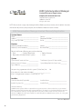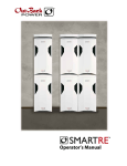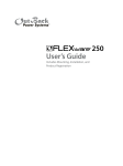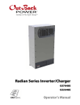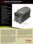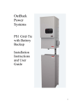
1
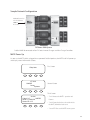
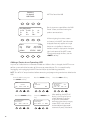
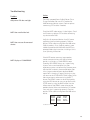
HUB
Communications Manager
User’s Manual
About OutBack Power Systems
OutBack Power Systems is a leader in advanced energy conversion technology. Our products include
true sine wave inverter/chargers, maximum power point charge controllers, system communication
components, as well as breaker panels, breakers, accessories, and assembled systems.
Notice of Copyright
OutBack HUB Communications Manager User’s Guide © 2008 All rights reserved.
Disclaimer
UNLESS SPECIFICALLY AGREED TO IN WRITING, OUTBACK POWER SYSTEMS:
(a) MAKES NO WARRANTY AS TO THE ACCURACY, SUFFICIENCY OR SUITABILITY OF ANY TECHNICAL OR
OTHER INFORMATION PROVIDED IN ITS MANUALS OR OTHER DOCUMENTATION.
(b) ASSUMES NO RESPONSIBILITY OR LIABILITY FOR LOSS OR DAMAGE, WHETHER DIRECT, INDIRECT,
CONSEQUENTIAL OR INCIDENTAL, WHICH MIGHT ARISE OUT OF THE USE OF SUCH INFORMATION.
THE USE OF ANY SUCH INFORMATION WILL BE ENTIRELY AT THE USER’S RISK.
Date and Revision: June 25, 2008
Contact Information
OutBack Power Systems
19009 62nd Ave. NE, Arlington, WA 98223
Phone (360) 435-6030
Fax (360) 435-6019
www.outbackpower.com
1
Warranty Introduction
Dear OutBack Customer,
Thank you for your purchase of OutBack products. We make every effort to assure our power
conversion products will give you long and reliable service for your renewable energy system.
As with any manufactured device, repairs might be needed due to damage, inappropriate use, or
unintentional defect. Please note the following guidelines regarding warranty service of OutBack
products:
• Any and all warranty repairs must conform to the terms of the warranty.
• All OutBack equipment must be installed according to their accompanying instructions and
manuals with specified over-current protection in order to maintain their warranties.
• The customer must return the component(s) to OutBack, securely packaged, properly addressed,
and shipping paid. We recommend insuring your package when shipping. Packages that are not
securely packaged can sustain additional damage not covered by the warranty or can void warranty
repairs.
• There is no allowance or reimbursement for an installer’s or user’s labor or travel time required to
disconnect, service, or reinstall the damaged component(s).
• OutBack will ship the repaired or replacement component(s) prepaid to addresses in the continental
United States, where applicable. Shipments outside the U.S. will be sent freight collect.
• In the event of a product malfunction, OutBack cannot bear any responsibility for consequential
losses, expenses, or damage to other components.
Please read the full warranty at the end of this manual for more information.
2
EU Declaration of Conformity
In accordance with EN 45014:1998
We ........................................................... OutBack Power Systems
Of ............................................................. 19009 62nd Ave NE
Arlington, WA 98223 USA
Declare that:
Model name/number ................. MATE, MATE2, MATE_B, HUB4, HUB10
Has been designed and manufactured to the following specifications:
73/23/EEC........................................... The Low Voltage Directive and its’ amending directives
As the manufacturer, we declare that the equipment named above has been designed to comply with
the relevant sections of the above referenced specifications. The unit complies with all essential requirements of the Directives.
Done at Arlington, WA USA
On 1/22/08
08
3
OUTBACK HUB
Communications Manager
INSTALLATION GUIDELINES AND SAFETY INSTRUCTIONS
SAVE THESE INSTRUCTIONS
Read all instructions, cautionary markings, and all appropriate sections of this installation and user
manual as well as other component manuals before using the system.
Be cautious around electricity, electrical components, and batteries. Shocks, burns, injury, and even
death can occur if an installer comes in contact with electricity.
This product is intended to be installed as part of a permanently grounded electrical system .
• The OutBack HUB is designed for indoor installation or installation inside a weatherproof enclosure.
• All wiring voltage is less than 30 volts DC (CAT5e communications cable) and considered a “limited
energy circuit” which normally does not require conduit (consult your local code for specific
installation requirements).
• Install all components and wiring according to national and local electrical and building codes. This
may include submitting a plan to the local building department and passing an inspection.
• For full system protection, one FLEXware Surge Protector per FX Series Inverter/Charger should be
installed.
OutBack Power Systems cannot be responsible for system failure, damages, or injury resulting from
improper installation of their products.
NOTE: In the United States, it is a UL 1741 requirement for a grid-tie system to have surge protection.
Installing an OutBack FW-SP is also recommended if your AC source is irregular or unreliable with
power surges (due to a lower quality generator or inconsistent utility power, for instance).
4
INTRODUCTION
OutBack Power Systems’ HUB System Communications Manager allows multiple OutBack
devices to connect and integrate at one point via CAT5e cable WITH RJ45 modular jacks.
There are two HUB Communication Manager products:
• HUB 4, which has four component ports plus a MATE port
• HUB 10, which has ten component ports plus a MATE port
When the MATE is attached to the HUB 4, it can display and manage any combination of four
FX Series Inverters/Chargers and OutBack Charge Controllers. The OutBack HUB 10 allows the
MATE to control up to 10 OutBack products of any combination.
NOTE: The OutBack HUB communicates stacking phase, load share, and incremental startup and shut down information directly among the FX Series Inverter/Chargers. The HUB is
powered by any FX or OutBack Charge Controller connected to it.
Both the HUB 4 and HUB 10 are the same size,
but differ in the number of available ports.
The snap-on wiring
cover protects cabling,
eliminating their
accidental plugging
and unplugging,
resulting in a cleaner
installation.
Gently spread the ends of
the cover to remove it.
5
HUB 10 and HUB 4 Parts
Each HUB comes with sufficient fasteners, cables and bushings for most common installations. Please
see the enclosed hardware kit for specific parts.
Accessories
OBCATV-3
OBCATV-6
OBCATV-10
OBCATV-50
Three-foot CAT5e cable with green jacket
Six-foot CAT5e cable with green jacket
Ten-foot CAT5e cable with green jacket
Fifty-foot CAT5e cable with green jacket
Mounting
The OutBack HUB can be wall-mounted in any orientation. Both the FLEXware 500 and 1000 systems
as well as previous OutBack enclosures have mounting holes for convenient HUB installation.
To mount a HUB to either a FLEXware 500 or 1000:
• Remove the knockout(s) from the side of the 500 or 1000
• Insert the snap-in bushing(s) supplied with the HUB.
• Secure the HUB using the supplied #10 sheet metal screws.
• Pull the CAT5e cable(s) through the knockout(s) and attach to the HUB Port(s).
Openings for #10 X 1/2”
Phillips screws (included
with each HUB)
FLEXware 500 AC Enclosure
Conduit knockout
removed
HUB 4 attached to enclosure
CAT5e cables are protected by
bushing inserted into conduit
knockout
To mount to a wall or other secure non-enclosure surface:
Either HUB model can be attached using two 1 5/8” drywall screws or their equivalent.
6
Connecting to the HUB
The Master FX plugs into Port 1
HUB Ports (HUB 10)
10
9
8
7
6
5
4
3
2
1
2nd MATE
Port is not
used
2nd
MATE
1st
MATE
• With the HUB mounted, plug in the FX Inverter/Chargers starting with Port 1.
• Port 1’s FX is the Master FX in a multiple FX system.
• When all the FXs are connected to the HUB, connect the Charge Controllers in any
order.
• After all devices are connected to the HUB, the MATE is always plugged in last using
the 1st MATE port.
• The 2nd MATE is inactive and should not be used.
• Connections can be made with FXs or OutBack Charge Controllers already powered
up or simply power up all devices when the connections to the HUB are complete.
• After the devices are powered, the MATE will power up when it is connected; it will
display a greeting and software revision information (see page 11)
• FX AC input breakers and AC output breakers should be open until stacking programming is complete.
• To operate, the HUB requires at least one FX or Charge/Controller to be plugged in.
• The MATE must be repolled to recognize any devices connected after it’s activated
(see page 12)
HUB Operation
When the first powered OutBack product plugs into the HUB:
• The HUB will go through a power up sequence that flashes all of its LEDs.
• The POWER LED will remain on any time that one or more powered OutBack products are
connected.
• After the MATE is connected it will start communicating with all connected devices.
• Each Port has an LED associated with it that is visible through the cover.
• Any device that is plugged in should have a flickering LED when the MATE is
communicating with it.
Note: In order to operate correctly, the HUB requires that the MATE be code version 2.0 or higher. (See
“Checking the MATE Version” in the Troubleshooting section and/or see the MATE User Manual for
more information.)
7
Common Wiring Configurations
Single FX Series Inverter/Charger and OutBack Controller
• Plug the FX into Port 1 of the HUB.
• The Charge Controller and any future OutBack devices can be plugged into any
remaining non-MATE ports.
Multiple OutBack Charge Controllers Only
• Plug one Charge Controller into Port 1 and the others into any remaining ports.
• A FLEXnet DC can be plugged into a remaining port as well.
Series/Parallel Phase-Stacked FX Series Inverter/Chargers
• The FX designated as the Master must be plugged into Port 1.
• Plug additional FXs in remaining ports in numerical order followed by any OutBack Charge
Controllers.
• Some PC monitoring software requires that 120/240 VAC series-stacked or series
parallel stacked FX Systems be wired with all LEG 1 (L1) phased FXs as odd numbered
Ports and all LEG 2 (L2) phased FXs as even numbered Ports. This arrangement
also makes programming the FX Slave power save level settings more intuitive.
Three- Phase FX Series Inverter/Charger Stacking
•
•
•
•
Connect the Master FX (Phase A) to Port 1.
Connect the phase B Slave to Port 2.
Connect the phase C Slave to Port 3.
The HUB jumper must be in the three phase position as described in the three- phase
stacking section (please see next page).
• Other OutBack devices can be plugged into any unused ports. Currently, only three
inverters can be configured in a three-phase arrangement, but additional non-stacked
inverters—all of which must be Masters—can be plugged into any of the unused ports of
the HUB.
• These non-stacked inverters can only power loads that are independent of the three-phase
loads; additional AC load panels will be required.
8
Three-Phase Stacking Only
The OutBack HUB is shipped from the factory setup for series (120/240 VAC split phase) and/or
parallel (120 VAC or 230 VAC single phase) stacking. If three-phase stacking is desired, the cover
must be removed and a jumper position changed. For three-phase stacking using a HUB 4:
1. Remove the black snap on wiring cover and all cables plugged into the HUB.
Label the cables to avoid confusion when
reconnecting.
2. Remove the four Phillips screws from the
bottom of the HUB.
Bottom cover removed
3. Remove bottom cover and remove the four
Phillips screws holding the green PCB to
the upper cover.
PCB removed
Jumper
9
Series/Parallel location
Three-Phase location
4. Move the plug-in jumper from the series/parallel location to the three-phase location.
5. Replace the PCB and bottom cover, the snap on wiring cover, and all CAT5e cables..
For three-phase stacking using a HUB 10, follow the same disassembly and assembly instructions as for
a HUB 4, but note that the jumper is in a different location as shown below.
HUB 10 PCB
Plug-in jumper
Jumper in series/
parallel location
Jumper in
three-phase
location
10
Sample Network Configuration
HUB 10 fastened to
side of FLEXware
1000 AC
Enclosure
FLEXware 1000 System
OutBack HUB 10 connected to four FX Series Inverter/Chargers and four Charge Controllers
MATE Power Up
As soon as the MATE cable is plugged into a powered OutBack product, the MATE itself will power-up
and display several information screens.
G’day Mate
(C) 2008
OutBack
Power
Systems
First Screen
Second Screen
Third Screen
Version
Code 4.0.5
OxBF5B
Serial #: 00000000
Screen EE 4.2.3
• “Code” dictates the MATE’s operation and
features
• “Serial #” matches the bar code sticker inside
the MATE, behind the back cover
• “Screen EE” refers to the MATE’s menu system
11
Searching
for Devices
HUB FOUND
Port Assignment
1> FX 2> MX
5>
6>
9>
10>
Silent
inv
chg
0.0 kw
0.0kw
DOWN
MATE has found the HUB
3>
7>
2M>
Port Assignment screen follows the “HUB
Found” screen, each Port showing the
product connected to it
4>
8>
While navigating the various screens
and menus in the MATE, the information
displayed often only applies to a single
device on a single Port. In these cases,
the Port number is displayed in the upper
right hand corner of the MATE screen.
To navigate through the Ports, use the
<PORT> soft key.
P01
zer 0.0 kw
buy 0.0 kw
STATUS
PORT
Adding a Device to an Operating HUB
Any time an OutBack device is removed or added to a HUB or its Port is changed, the MATE must repoll the system to find the locations of all the new or moved devices. This is accomplished by
unplugging and re-plugging the MATE from the HUB, or by the following procedure.
NOTE: Turn off all AC output breakers before connecting and programming new devices added to the
HUB.
From the MAIN screen, press
the <SETUP> soft key
MAIN-----------------------------------12:00:00P
SETUP --------------------------choose device:
SUM
FX
STATUS
SETUP ADV
Press the <COMM> soft key
12
Press the <MATE> soft key
MATE
Press the <REPOLL> soft
key
SETUP/MATE/PAGE2----------------choose category:
SETUP/MATE/ COMM------------choose category:
PG1
BACK
SUMRY
COMM
PG3
REPOLL
PC
DEBUG
Press the <PG2> soft key
SETUP/MATE/PAGE1----------------mate code rev:
4.0.5
choose category:
CLOCK
CNT
GLOW
PG2
After repolling, the MATE will
display a Searching for Devices
screen followed by the Port
Assignment screen before
returning to the choose category
screen. MATEs with software
revision 4.0.0 or higher repoll
automatically every 30 seconds.
Troubleshooting
Problem
Action
HUB power LED does not light
The HUB is powered from OutBack Power FXs or
Charge Controllers. Be sure all DC breakers for
HUB-connected devices are on. Check or replace
connecting CAT5e cables if needed.
MATE does not find the hub
Check the MATE code version is 2.0 or higher. Check
and if necessary replace CAT5e cables connecting
any device to the HUB.
MATE does not see all connected
devices
MATE displays a ‘COMM ERROR’
Verify that all connected devices have DC power
applied and are functioning properly. Check or
replace CAT5e cables running from the HUB to the
OutBack products. If any OutBack products were
added or moved on the HUB while the MATE was
powered, follow the instructions in Adding a Device
to an Operating HUB section
If the MATE receives too many interrupted or
corrupt communications with HUB-attached
devices, it will display a COMM ERROR screen.
Choosing VIEW DEBUG brings up a screen listing
all ports and accumulated errors. Any Port
experiencing errors can be found by the error count
after the Port number. In the example below, Port
4 has a large number of errors detected (04:025
means Port 4: showing 25 errors). Pressing any key
will return to the SETUP/MATE/COMM screen, which
allows error counts to be reset using the ‘RSET’
button. The DEBUG screen can be re-displayed by
using the VIEW button, or user can get back to the
SETUP menu by using the BACK button. Use the
information on the DEBUG screen to locate the
problem device. Make sure the device’s DC breaker
is on, and that it is operating correctly. Check or
replace CAT5e cables running from the HUB to that
device.
00:000
03:000
06:001
09:001
01:000
04:025
07:001
10:001
02:000
05:001
08:001
2M:001
25 errors on Port 4
13
TWO YEAR LIMITED WARRANTY INFORMATION
Hub Communications Manager Products
OutBack Power Systems, Inc. (“OutBack”) provides a two year (2) limited warranty (“Warranty”) against
defects in materials and workmanship for its Hub Communications Manager Products (“Product(s)”) if
installed in fixed location applications.
The term of this Warranty begins on the Product(s) date of manufacture or the initial purchase date as
indicated on the warranty registration card submitted to OutBack, whichever is greater. This Warranty
applies to the original OutBack Product(s) purchaser, and is transferable only if the Product(s) remains
installed in the original use location. The warranty does not apply to any Product(s) or Product(s) part
that has been modified or damaged by the following:
•
•
•
•
•
•
•
•
•
•
•
•
•
Installation or Removal;
Alteration or Disassembly;
Normal Wear and Tear;
Accident or Abuse;
Corrosion;
Lightning;
Repair or service provided by an unauthorized repair facility;
Contrary to manufacturer product instructions;
Fire, Floods or Acts of God;
Shipping or Transportation;
Incidental or consequential damage caused by other components of the power system;
Any product whose serial number has been altered, defaced or removed; or
Any other event not foreseeable by OutBack.
OutBack’s liability for any defective Product(s), or any Product(s) part, shall be limited to the repair
or replacement of the Product(s), at OutBack’s discretion. OutBack does not warrant or guarantee
workmanship performed by any person or firm installing its Product(s). This Warranty does not cover
the costs of installation, removal, shipping (except as described below), or reinstallation of Product(s).
Revision.2008-04-01
14
To request warranty service, you must contact OutBack Technical Services at (360) 435-6030 or [email protected] within the effective warranty period. OutBack Technical Support will attempt to troubleshoot the product and validate that the failure is product related. If warranty service
is required, OutBack will issue a Return Material Authorization (RMA) number. A request for an RMA
number requires all of the following information:
1. Proof-of-purchase in the form of a copy of the original Product(s) purchase invoice or receipt
confirming the Product(s) model number and serial number;
2. Description of the problem; and
3. Shipping address for the repaired or replacement equipment.
After receiving the RMA number, pack the Product(s) authorized for return, along with a copy of the
original purchase invoice, in the original Product(s) shipping container(s) or packaging providing
equivalent protection and mark the outside clearly with the RMA number. The sender must prepay all
shipping charges to the agreed upon OutBack Power Systems location, and insure the shipment, or
accept the risk of loss or damage during shipment. OutBack is not responsible for shipping damage
caused by improperly packaged Products, the repairs this damage might require, or the costs of these
repairs. If, upon receipt of the Product(s), OutBack determines the Product(s) is defective and that the
defect is covered under the terms of this Warranty, OutBack will then and only then ship a repaired or
replacement Product(s) to the purchaser freight prepaid, non-expedited, using a carrier of OutBack’s
choice, where applicable.
The warranty period of any repaired or replacement Product is twelve (12) months from the date of
shipment from OutBack, or the remainder of the initial warranty term, which ever is greater.
THIS LIMITED WARRANTY IS THE EXCLUSIVE WARRANTY APPLICABLE TO OUTBACK PRODUCTS.
OUTBACK EXPRESSLY DISCLAIMS ANY OTHER EXPRESS OR IMPLIED WARRANTIES OF ITS PRODUCTS,
INCLUDING BUT NOT LIMITED TO ANY IMPLIED WARRANTIES OF MERCHANTABILITY OR FITNESS FOR A
PARTICULAR PURPOSE. OUTBACK ALSO EXPRESSLY LIMITS ITS LIABILITY IN THE EVENT OF A PRODUCT
DEFECT TO REPAIR OR REPLACEMENT IN ACCORDANCE WITH THE TERMS OF THIS LIMITED WARRANTY
AND EXCLUDES ALL LIABILITY FOR INCIDENTAL OR CONSEQUENTIAL DAMAGES, INCLUDING
WITHOUT LIMITATION ANY LIABILITY FOR PRODUCTS NOT BEING AVAILABLE FOR USE OR LOST
REVENUES OR PROFITS, EVEN IF IT IS MADE AWARE OF SUCH POTENTIAL DAMAGES. SOME STATES (OR
JURISDICTIONS) MAY NOT ALLOW THE EXCLUSION OR LIMITATION OF WARRANTIES OR DAMAGES, SO
THE ABOVE EXCLUSIONS OR LIMITATIONS MAY NOT APPLY TO YOU.
Revision.2008-04-01
15
HUB Communcations Manager
Limited Warranty Registration
Complete this form and return it to:
Outback Power Systems Inc.
19009 62nd Ave. NE
Arlington, WA 98223
NOTE: Please submit a copy (not the original) of the Product purchase invoice, which confirms the date
and location of purchase, the price paid, and the Product Model and Serial Number.
HUB Comunications Manager Limited Warranty Registration
System Owner
Name: _______________________________
Address: ______________________________
City, State, Zip Code: ____________________
Country: ______________________________
Telephone Number:______________________
E-mail: ________________________________
Product
Product(s) Model Number(s): ______________
Product(s) Serial Number(s):_______________
Sold by: ______________________________
Purchase Date: _________________________
Please circle factors affecting your purchase decision:
• Price
• Product Reputation
• Product Features
• Reputation of OutBack Power Systems
• Value
System
System Install/Commission Date: ______________
Nominal System AC Voltage: __________________
Type of Batteries: ___________________________
Total Nominal System AC Output in KW:________
System Battery Bank Size (Amp Hours):_________
Are you using a generator with this system? (Circle One): Yes
No
If yes, please list the make and model: _______________________
If yes, is the generator’s output is (Circle One): AC DC
Installer:
Contractor Number (If Applicable) _____________
Installer City, State, Zip: ______________________
Installer Address: __________________________
Installer E-mail:____________________________
*Extended Warranty
OutBack Power Systems offers an optional three (3) year extension to the standard two (2) year Limited
Warranty for the Hub Communications Manager Products. To request a 3-year Limited Warranty extension
for a total effective warranty coverage period of five (5) years; include a check or money order in the
amount of $50USD for a Hub 10 or $35USD for a Hub 4 payable to OutBack Power Systems, Inc. along with
your Warranty Registration.
Revision.2008-04-01
16
17
Corporate Office
19009 62nd Avenue NE
Arlington, WA USA
(+1) 360-435-6030
www.outbackpower.com
European Sales Office
C/ Castelló, 17
08830 - Sant Boi de Llobregat
BARCELONA, España
Phone: +34.93.654.9568
900-0004-01-00 REV B