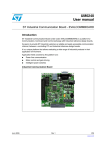
1
UM0239
User manual
ST7540 Power Line Modem Demokit
Graphical User Interface (GUI)
Introduction
The "ST7538/40 FSK Power Line Modem Demo Kit" is a software tool that allows interfacing one or more
ST Power Line Modem (PLM) Demo Boards with a Personal Computer. Only PLM Demo Boards
equipped with ST7538 and ST7540 devices are supported.
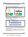
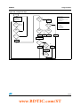
The typical Application Environment consists of a PC that communicates, through a ST7 microcontroller
placed on a general purpose board called "EVALCOMMBOARD" (see Section 1.5), with a Power Line
Modem Board equipped with ST7538 or ST7540 products as shown in Figure . The interface used to
communicate between the PC and the EVALCOMMBOARD is the RS-232 (USB interface will be
supported in future). At start-up, the Software recognizes automatically which type of device is connected
to PC and modifies its appearance differently for the ST7538 or the ST7540.
This document describes the ST7540 operating mode (see Section 1.5).
A schematic of the application environment
MAINS
EVALST7538DUAL
or
EVALST7540-1
ST7538 or ST7540
EVALCOMMBOARD
ST7 µC
RS-232 or USB
CTRL REGISTER PROGRAMMING
PERSONAL
COMPUTER
RX SESSION
TX SESSION
PING SESSION
ST7538/40 DEMOKIT
GUI
With the "ST7538/40 FSK Power Line Modem Demo Kit" it is possible to:
●
Write/read ST7540 (or ST7538) Control Register
●
Open a Tx session
●
Open a Rx session
●
Open a Ping session (minimum two devices required)
July 2006
Rev 1
1/44
www.st.com
www.BDTIC.com/ST
Contents
UM0239
Contents
1
Installation information . . . . . . . . . . . . . . . . . . . . . . . . . . . . . . . . . . . . . . . 6
1.1
Software license agreement . . . . . . . . . . . . . . . . . . . . . . . . . . . . . . . . . . . . 6
1.2
System requirements . . . . . . . . . . . . . . . . . . . . . . . . . . . . . . . . . . . . . . . . . 7
1.3
Installing the software . . . . . . . . . . . . . . . . . . . . . . . . . . . . . . . . . . . . . . . . . 7
1.4
Release information and boards supported . . . . . . . . . . . . . . . . . . . . . . . . 8
1.5
Reference documents . . . . . . . . . . . . . . . . . . . . . . . . . . . . . . . . . . . . . . . . 8
2
Commonly used terms . . . . . . . . . . . . . . . . . . . . . . . . . . . . . . . . . . . . . . . 9
3
User interface . . . . . . . . . . . . . . . . . . . . . . . . . . . . . . . . . . . . . . . . . . . . . 10
4
3.1
Menu bar . . . . . . . . . . . . . . . . . . . . . . . . . . . . . . . . . . . . . . . . . . . . . . . . . 10
3.2
Toolbar . . . . . . . . . . . . . . . . . . . . . . . . . . . . . . . . . . . . . . . . . . . . . . . . . . . 11
3.3
Status bar . . . . . . . . . . . . . . . . . . . . . . . . . . . . . . . . . . . . . . . . . . . . . . . . . 12
Getting started . . . . . . . . . . . . . . . . . . . . . . . . . . . . . . . . . . . . . . . . . . . . . 13
4.1
Selecting the COM port . . . . . . . . . . . . . . . . . . . . . . . . . . . . . . . . . . . . . . 13
4.2
Setting the Control Register parameters . . . . . . . . . . . . . . . . . . . . . . . . . 14
4.2.1
Carrier Frequency . . . . . . . . . . . . . . . . . . . . . . . . . . . . . . . . . . . . . . . . . 15
4.2.2
Baudrate . . . . . . . . . . . . . . . . . . . . . . . . . . . . . . . . . . . . . . . . . . . . . . . . 16
4.2.3
Deviation . . . . . . . . . . . . . . . . . . . . . . . . . . . . . . . . . . . . . . . . . . . . . . . . 16
4.2.4
Interfacing mode . . . . . . . . . . . . . . . . . . . . . . . . . . . . . . . . . . . . . . . . . . 16
4.2.5
Watchdog . . . . . . . . . . . . . . . . . . . . . . . . . . . . . . . . . . . . . . . . . . . . . . . . 17
4.2.6
Transmission timeout . . . . . . . . . . . . . . . . . . . . . . . . . . . . . . . . . . . . . . . 17
4.2.7
Detection method . . . . . . . . . . . . . . . . . . . . . . . . . . . . . . . . . . . . . . . . . . 17
4.2.8
Frequency detection time . . . . . . . . . . . . . . . . . . . . . . . . . . . . . . . . . . . . 18
4.2.9
Output voltage freeze . . . . . . . . . . . . . . . . . . . . . . . . . . . . . . . . . . . . . . . 18
4.2.10
Output clock . . . . . . . . . . . . . . . . . . . . . . . . . . . . . . . . . . . . . . . . . . . . . . 18
4.2.11
Header recognition . . . . . . . . . . . . . . . . . . . . . . . . . . . . . . . . . . . . . . . . 18
4.2.12
Frame length count . . . . . . . . . . . . . . . . . . . . . . . . . . . . . . . . . . . . . . . . 19
4.2.13
Header length . . . . . . . . . . . . . . . . . . . . . . . . . . . . . . . . . . . . . . . . . . . . 19
4.2.14
Extended control register . . . . . . . . . . . . . . . . . . . . . . . . . . . . . . . . . . . . 19
4.2.15
Sensitivity mode . . . . . . . . . . . . . . . . . . . . . . . . . . . . . . . . . . . . . . . . . . . 20
4.2.16
Pre-filter . . . . . . . . . . . . . . . . . . . . . . . . . . . . . . . . . . . . . . . . . . . . . . . . . 20
2/44
www.BDTIC.com/ST
UM0239
Contents
4.2.17
Frame header . . . . . . . . . . . . . . . . . . . . . . . . . . . . . . . . . . . . . . . . . . . . 20
4.2.18
Frame length . . . . . . . . . . . . . . . . . . . . . . . . . . . . . . . . . . . . . . . . . . . . . 20
4.2.19
Limitations on Control Register parameters . . . . . . . . . . . . . . . . . . . . . 21
4.3
Selecting the Dual Channel option . . . . . . . . . . . . . . . . . . . . . . . . . . . . . . 21
4.4
Monitoring events . . . . . . . . . . . . . . . . . . . . . . . . . . . . . . . . . . . . . . . . . . . 22
4.5
Using the Control Register String . . . . . . . . . . . . . . . . . . . . . . . . . . . . . . . 23
4.6
Reading/Writing Control Register parameters . . . . . . . . . . . . . . . . . . . . . 24
5
Transmission sessions . . . . . . . . . . . . . . . . . . . . . . . . . . . . . . . . . . . . . . 25
6
Receive sessions . . . . . . . . . . . . . . . . . . . . . . . . . . . . . . . . . . . . . . . . . . 26
7
Ping sessions . . . . . . . . . . . . . . . . . . . . . . . . . . . . . . . . . . . . . . . . . . . . . 28
7.1
7.2
8
7.1.1
Ping Master parameters . . . . . . . . . . . . . . . . . . . . . . . . . . . . . . . . . . . . 29
7.1.2
Starting a Master Ping session . . . . . . . . . . . . . . . . . . . . . . . . . . . . . . . 30
Opening a Ping Slave session . . . . . . . . . . . . . . . . . . . . . . . . . . . . . . . . . 31
7.2.1
Ping Slave parameters . . . . . . . . . . . . . . . . . . . . . . . . . . . . . . . . . . . . . . 31
7.2.2
Starting a Slave Ping session . . . . . . . . . . . . . . . . . . . . . . . . . . . . . . . . 32
7.3
Ping protocol . . . . . . . . . . . . . . . . . . . . . . . . . . . . . . . . . . . . . . . . . . . . . . 32
7.4
Ping session flowcharts . . . . . . . . . . . . . . . . . . . . . . . . . . . . . . . . . . . . . . 34
Communication session examples . . . . . . . . . . . . . . . . . . . . . . . . . . . . 36
8.1
9
Opening a Ping Master session . . . . . . . . . . . . . . . . . . . . . . . . . . . . . . . . 29
Setup procedure . . . . . . . . . . . . . . . . . . . . . . . . . . . . . . . . . . . . . . . . . . . . 36
8.1.1
Required hardware . . . . . . . . . . . . . . . . . . . . . . . . . . . . . . . . . . . . . . . . 36
8.1.2
Hardware setup . . . . . . . . . . . . . . . . . . . . . . . . . . . . . . . . . . . . . . . . . . . 36
8.1.3
Software setup . . . . . . . . . . . . . . . . . . . . . . . . . . . . . . . . . . . . . . . . . . . . 36
8.2
Communication session without Frame Synchronization . . . . . . . . . . . . . 37
8.3
Communication session with Frame Synchronization . . . . . . . . . . . . . . . 39
8.4
Communication session with Hardware Frame Synchronization . . . . . . . 40
8.5
Ping session . . . . . . . . . . . . . . . . . . . . . . . . . . . . . . . . . . . . . . . . . . . . . . . 41
Revision history . . . . . . . . . . . . . . . . . . . . . . . . . . . . . . . . . . . . . . . . . . . 43
3/44
www.BDTIC.com/ST
List of tables
UM0239
List of tables
Table 1.
Table 2.
Table 3.
Table 4.
Table 5.
Table 6.
Table 7.
Table 8.
Table 9.
Table 10.
Table 11.
Table 12.
Table 13.
Table 14.
Table 15.
Table 16.
Table 17.
Table 18.
Table 19.
Table 20.
Table 21.
Table 22.
Table 23.
Table 24.
Table 25.
Table 26.
Commonly used terms . . . . . . . . . . . . . . . . . . . . . . . . . . . . . . . . . . . . . . . . . . . . . . . . . . . . . 9
Menu bar commands . . . . . . . . . . . . . . . . . . . . . . . . . . . . . . . . . . . . . . . . . . . . . . . . . . . . . 11
Summary of Control Register parameters . . . . . . . . . . . . . . . . . . . . . . . . . . . . . . . . . . . . . 15
Carrier frequency . . . . . . . . . . . . . . . . . . . . . . . . . . . . . . . . . . . . . . . . . . . . . . . . . . . . . . . . 16
Baudrate . . . . . . . . . . . . . . . . . . . . . . . . . . . . . . . . . . . . . . . . . . . . . . . . . . . . . . . . . . . . . . . 16
Deviation . . . . . . . . . . . . . . . . . . . . . . . . . . . . . . . . . . . . . . . . . . . . . . . . . . . . . . . . . . . . . . . 16
Mains interfacing mode. . . . . . . . . . . . . . . . . . . . . . . . . . . . . . . . . . . . . . . . . . . . . . . . . . . . 16
Watchdog . . . . . . . . . . . . . . . . . . . . . . . . . . . . . . . . . . . . . . . . . . . . . . . . . . . . . . . . . . . . . . 17
Transmission timeout . . . . . . . . . . . . . . . . . . . . . . . . . . . . . . . . . . . . . . . . . . . . . . . . . . . . . 17
Detection method . . . . . . . . . . . . . . . . . . . . . . . . . . . . . . . . . . . . . . . . . . . . . . . . . . . . . . . . 17
Frequency detection time . . . . . . . . . . . . . . . . . . . . . . . . . . . . . . . . . . . . . . . . . . . . . . . . . . 18
Output voltage freeze . . . . . . . . . . . . . . . . . . . . . . . . . . . . . . . . . . . . . . . . . . . . . . . . . . . . . 18
Output clock . . . . . . . . . . . . . . . . . . . . . . . . . . . . . . . . . . . . . . . . . . . . . . . . . . . . . . . . . . . . 18
Header recognition . . . . . . . . . . . . . . . . . . . . . . . . . . . . . . . . . . . . . . . . . . . . . . . . . . . . . . . 19
Frame Length Count . . . . . . . . . . . . . . . . . . . . . . . . . . . . . . . . . . . . . . . . . . . . . . . . . . . . . . 19
Header Length . . . . . . . . . . . . . . . . . . . . . . . . . . . . . . . . . . . . . . . . . . . . . . . . . . . . . . . . . . 19
Extended control register . . . . . . . . . . . . . . . . . . . . . . . . . . . . . . . . . . . . . . . . . . . . . . . . . . 20
Sensitivity mode . . . . . . . . . . . . . . . . . . . . . . . . . . . . . . . . . . . . . . . . . . . . . . . . . . . . . . . . . 20
Pre-filter . . . . . . . . . . . . . . . . . . . . . . . . . . . . . . . . . . . . . . . . . . . . . . . . . . . . . . . . . . . . . . . 20
Pre-filter . . . . . . . . . . . . . . . . . . . . . . . . . . . . . . . . . . . . . . . . . . . . . . . . . . . . . . . . . . . . . . . 20
Frame length. . . . . . . . . . . . . . . . . . . . . . . . . . . . . . . . . . . . . . . . . . . . . . . . . . . . . . . . . . . . 21
Limitations on control register parameters . . . . . . . . . . . . . . . . . . . . . . . . . . . . . . . . . . . . . 21
Summary of events . . . . . . . . . . . . . . . . . . . . . . . . . . . . . . . . . . . . . . . . . . . . . . . . . . . . . . . 22
Ping master parameters . . . . . . . . . . . . . . . . . . . . . . . . . . . . . . . . . . . . . . . . . . . . . . . . . . . 29
Ping slave parameters . . . . . . . . . . . . . . . . . . . . . . . . . . . . . . . . . . . . . . . . . . . . . . . . . . . . 31
Revision history . . . . . . . . . . . . . . . . . . . . . . . . . . . . . . . . . . . . . . . . . . . . . . . . . . . . . . . . . 43
4/44
www.BDTIC.com/ST
UM0239
List of figures
List of figures
Figure 1.
Figure 2.
Figure 3.
Figure 4.
Figure 5.
Figure 6.
Figure 7.
Figure 8.
Figure 9.
Figure 10.
Figure 11.
Figure 12.
Figure 13.
Figure 14.
Figure 15.
Figure 16.
Figure 17.
Figure 18.
Figure 19.
Figure 20.
Figure 21.
Figure 22.
Figure 23.
Figure 24.
Figure 25.
Figure 26.
Figure 27.
Figure 28.
Main window . . . . . . . . . . . . . . . . . . . . . . . . . . . . . . . . . . . . . . . . . . . . . . . . . . . . . . . . . . . . 10
Toolbar controls . . . . . . . . . . . . . . . . . . . . . . . . . . . . . . . . . . . . . . . . . . . . . . . . . . . . . . . . . 11
ST7540 status bar . . . . . . . . . . . . . . . . . . . . . . . . . . . . . . . . . . . . . . . . . . . . . . . . . . . . . . . 12
COM selection . . . . . . . . . . . . . . . . . . . . . . . . . . . . . . . . . . . . . . . . . . . . . . . . . . . . . . . . . . 13
Device selection and communication error during COM selection . . . . . . . . . . . . . . . . . . . 14
Control Register window . . . . . . . . . . . . . . . . . . . . . . . . . . . . . . . . . . . . . . . . . . . . . . . . . . . 14
ST7540 Control Register parameters . . . . . . . . . . . . . . . . . . . . . . . . . . . . . . . . . . . . . . . . . 15
Dual channel selection panel . . . . . . . . . . . . . . . . . . . . . . . . . . . . . . . . . . . . . . . . . . . . . . . 22
Events panel . . . . . . . . . . . . . . . . . . . . . . . . . . . . . . . . . . . . . . . . . . . . . . . . . . . . . . . . . . . . 22
Write control register string and parameters position . . . . . . . . . . . . . . . . . . . . . . . . . . . . . 23
Control register writing/reading procedures . . . . . . . . . . . . . . . . . . . . . . . . . . . . . . . . . . . . 24
Read CTRL Register dialog box . . . . . . . . . . . . . . . . . . . . . . . . . . . . . . . . . . . . . . . . . . . . . 24
Transmission Monitor dialog box . . . . . . . . . . . . . . . . . . . . . . . . . . . . . . . . . . . . . . . . . . . . 25
Receive Monitor dialog box . . . . . . . . . . . . . . . . . . . . . . . . . . . . . . . . . . . . . . . . . . . . . . . . 26
Ping windows . . . . . . . . . . . . . . . . . . . . . . . . . . . . . . . . . . . . . . . . . . . . . . . . . . . . . . . . . . . 28
Ping Master dialog box . . . . . . . . . . . . . . . . . . . . . . . . . . . . . . . . . . . . . . . . . . . . . . . . . . . . 29
Ping slave window . . . . . . . . . . . . . . . . . . . . . . . . . . . . . . . . . . . . . . . . . . . . . . . . . . . . . . . 31
Ping message format . . . . . . . . . . . . . . . . . . . . . . . . . . . . . . . . . . . . . . . . . . . . . . . . . . . . . 32
Ping master loop . . . . . . . . . . . . . . . . . . . . . . . . . . . . . . . . . . . . . . . . . . . . . . . . . . . . . . . . . 34
Ping slave loop . . . . . . . . . . . . . . . . . . . . . . . . . . . . . . . . . . . . . . . . . . . . . . . . . . . . . . . . . . 35
Communication setup: COM selection . . . . . . . . . . . . . . . . . . . . . . . . . . . . . . . . . . . . . . . 36
Control Register dialog boxes after setup. . . . . . . . . . . . . . . . . . . . . . . . . . . . . . . . . . . . . . 37
Communication without Frame Synchronization example . . . . . . . . . . . . . . . . . . . . . . . . . 38
Demodulation timings for RX with preamble detection (@2400 baud) . . . . . . . . . . . . . . . . 38
Communication with Frame Synchronization example . . . . . . . . . . . . . . . . . . . . . . . . . . . . 39
Communication with Hardware Frame Synchronization . . . . . . . . . . . . . . . . . . . . . . . . . . . 41
Ping master session and save statistics . . . . . . . . . . . . . . . . . . . . . . . . . . . . . . . . . . . . . . . 42
Ping slave session and save statistics . . . . . . . . . . . . . . . . . . . . . . . . . . . . . . . . . . . . . . . . 42
5/44
www.BDTIC.com/ST
Installation information
1
Installation information
1.1
Software license agreement
1.
UM0239
Important
Before loading this software you have to carefully read and agree to the following terms and
conditions which will be then automatically agreed on by loading this Software or any portion
thereof. If you do not agree to the terms of this Agreement, do not install or use anyhow this
software or any portion thereof.
2.
License grant
ST grants you a non-exclusive, royalty-free, worldwide license to this software written for ST
products (“Software”). You shall have the right to use, copy, modify and distribute the
Software with ST products only. All ST Software will be required to contain the ST Copyright
notice which shall not be removed therefrom for any reason. You acknowledge that the
Software is not designed nor is authorized for use in life supporting devices or systems.
3.
Ownership and copyright of software
Title to the Software and all copies thereof remain with ST. The Software is copyrighted and
protected by worldwide copyright laws and international treaty provisions. Except as
expressly provided herein, ST does not grant any express or implied right to you under ST
patents, copyrights, trademarks, or trade secret information.
4.
Warranties and liabilities
ST makes no warranty express or implied including but not limited to, any warranty of (i)
merchantability or fitness for a particular purpose and/or (ii) requirements, for a particular
purpose in relation to the Software which is provided ON AN "AS IS" BASIS.
All warranties, conditions or other terms implied by law are excluded to the fullest extent
permitted by law.
ST shall not be liable for any claim made by you and/or against you by a third party, in
relation to the Software under this Agreement.
You take responsibility for the suitability, selection, use and management of the Software
and the results obtained there from as well as their combination and the combination of the
elements thereof with other apparatus, equipment, products, programs and services.
Nothing contained in these terms shall be construed as a warranty or representation by ST
as to the validity or scope of any and all IPR in respect of which a license is herein granted
or constitutes a warranty or representation that any manufacture, use or sale by you
hereunder shall be free from infringement of any Intellectual Property Rights (IPR) other
than those under which and to the extent to which rights thereto are granted hereunder or
constitute an agreement to bring or prosecute actions or suits against third parties for
infringements or confer any right upon a party to use in advertising, publicity or other
medium, any name trademark or trade name or any other contraction abbreviation or
simulation thereto of the other party or confer by implication estoppel or otherwise upon you
any license or other right under any and all IPR except the licenses and rights expressly
granted hereunder to you.
In no event shall ST be liable for any damages whatsoever (including, without limitation,
damages for loss of business revenue or profits, business interruption, loss of business
information or other pecuniary loss) arising out of the use of or the inability to use the
Software as part of an ST application. ST does not assume any responsibility for any errors
that may appear in the Software nor any responsibility to support or update the Software. ST
6/44
www.BDTIC.com/ST
UM0239
Installation information
retains the right to make changes to the Software and its test specifications at any time,
without notice.
5.
Entire agreement
This Agreement constitutes the entire agreement with ST and supersedes any prior or
contemporaneous oral or written agreements with respect to the subject matter of this
Agreement.
6.
Support
Under this Agreement, ST is under no obligation to assist in the use of the Software, to
provide you support of the Software, or to provide maintenance, correction, modification,
enhancement, or upgrades to the Software. Any action taken by ST in this respect will be
unilaterally taken and subject only to ST assessment - without any notice to you. Any such
action shall be considered as Software and will automatically be subject to this Agreement.
7.
Termination of this license
ST is entitled to terminate this Software License Agreement at any time if you are in breach
of any of the terms of this Agreement. Upon termination, you will immediately destroy the
Software.
8.
Export regulations
You undertake to comply with all applicable laws, regulations, decrees and ordinances
related to your use of the Software.
9.
Applicable laws
Any dispute arising out of or in connection with this Agreement which could not be amicably
settled shall be finally settled under the Rules of Conciliation and Arbitration of the
international Chamber of Commerce by one or more arbitrators appointed in accordance
with the said Rules which the Parties know and elect irrevocably. Such arbitration shall take
place in Paris and be held in English.
1.2
System requirements
A Personal Computer (PC) including:
1.3
●
one or more RS-232 serial ports
●
a CD-ROM reader
●
a Hard Disk with at least 20 MBytes of free space
●
Screen resolution 800x600 or higher
●
Operating System Windows NT/2000/XP
●
Adobe Acrobat Reader release 4.0 or more recent
Installing the software
To install the software:
1.
Insert the ST7538/40 Demo Board CD-ROM in your PC and execute the setup.exe file.
2.
Follow the instructions displayed by the application wizard.
To run the software:
1.
Execute the ST7538/40 PLM Demo Kit program (Start →Programs →ST7538_40
FSK PowerLine Modem Demo Kit →ST7538_40 FSK PowerLine Modem Demo Kit).
7/44
www.BDTIC.com/ST
Installation information
1.4
UM0239
Release information and boards supported
This document refers to Release 3.19 of the "ST7538/40 FSK PowerLine Modem Demo Kit".
The following Evaluation Boards are supported by the "ST7538/40 FSK PowerLine Modem
Demo Kit":
1.5
●
ST7538 Evaluation Board rev. 2.1 & rev. 2.2
●
EVALCOMMBOARD rev. 1.1 + EVALST7538DUAL rev. 3.1 Dual Channel
●
EVALCOMMBOARD rev. 1.1 + EVALST7540-1 rev. 2.1
Reference documents
For more information about the EVALCOMMBOARD please refer to "UM0240 User Manual
Industrial Communication Board - EVALCOMMBOARD"
For ST7538 working mode, please refer to "UM0241 User Manual ST7538 Power Line
Modem Demokit GUI".
8/44
www.BDTIC.com/ST
UM0239
2
Commonly used terms
Commonly used terms
Table 1 describes some of the commonly used terms regarding Power Line Communication
and other terms used in this document:
Table 1.
Term
Commonly used terms
Description
FCS
Frame Check Sequence. An error detection scheme that uses parity bits generated
by polynomial encoding of digital signals.
FEC
Forward Error Correction. A system of error control for data transmission wherein the
receiving device has the capability to detect and correct any character or code block
that contains less than a predetermined number of symbols in error. FEC is
accomplished by adding bits to each transmitted character or code block, using a
predetermined algorithm.
MAC
Medium Access Control. A service feature or technique used to permit or deny use of
a communication medium.
Mains
The electrical network that supplies homes and businesses with power.
Ping
Program that measures the time elapsed between the transmission of multiple
packets to a remote device and the return to origin (real meaning). In this document,
the term ping is used to describe a packet exchange process between a Master
device and one or more Slave devices, collecting statistical data about the integrity of
packets.
PLC
Power Line Communication. Communication performed between two or more nodes
of the electrical network.
PLM
Power Line Modem. A device able to transmit and receive information across the
electrical network. To ensure reliability of communication, digital data are transformed
modulating a carrier signal in transmission and demodulating such a carrier in
reception.
9/44
www.BDTIC.com/ST
User interface
3
UM0239
User interface
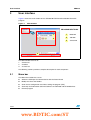
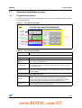
Figure 1 shows the main window of the "ST7538/40 FSK PowerLine Modem Demo Kit"
program.
Figure 1.
Main window
PROGRAM SECTIONS:
1
1
MENU BAR
2
2
TOOLBAR
3
STATUS BAR
3
The Main Window consists of:
1.
A menu bar
2.
A toolbar
3.
A status bar
The following sections provide a complete description for each component.
3.1
Menu bar
The Menu Bar enables the user to:
●
Select the COM port for communication with the Demo Board
●
Modify the size of the Toolbar
●
Save the last configuration used when exiting the program (GUI)
●
View help and information about this Software and ST7538 and ST7540 devices
●
Exit the program
10/44
www.BDTIC.com/ST
UM0239
User interface
Table 2 summarizes the list of commands available in the menu bar and their functions:
Table 2.
Menu bar commands
Menu voice
File
Commands
Help
Submenu voice
Function
Exit
Exits from the Program
COM settings
Opens COM port selected and begins the
communication with the Demo Board (ports
available from COM1 to COM4)
Toolbar size
Selects the size of the toolbar (small,
medium or large)
Save on Exit
On exit saves the current program
settings(1)
ST7538 Demo kit GUI User Manual
Opens the “ST7538 PowerLine Modem
Demo Kit GUI- User Manual”
ST7540 Demo kit GUI User Manual
Opens this document
ST7538 Datasheet
Opens ST7538 specification document
ST7540 Datasheet
Opens ST7540 specification document
About
Shows information about Software Release
1. Settings saved refer to all controls present in the “ST7538/40 FSK PowerLine Modem Demo Kit” tool.
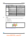
3.2
Toolbar
The Toolbar is used to access all sections of the program. The sections available are:
●
Receiving session
●
Transmission session
●
Control Register access
●
Ping session
Figure 2.
Toolbar controls
TX SESSION PING SESSION
RX SESSION
CR ACCESS
1
Toolbar sections are not available until the correct COM port is selected as described in
Section 4.1: Selecting the COM port on page 13.
11/44
www.BDTIC.com/ST
User interface
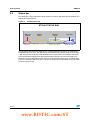
3.3
UM0239
Status bar
The Status Bar shows information about software, firmware and about the link between PC
and the Evaluation Board.
Figure 3.
ST7540 status bar
ST7540 STATUS BAR
COM port
Selected
Software
release
Firmware
release
Link status
The left side of the Status Bar indicates the selected COM port by means of Command→
COM Settings menu voice. The SW version field indicates the software release. To the right,
a text string shows the device used (ST7540 in this case) and the the Firmware release of
ST7 microcontroller equipped on IBU Communication Board. The LED to the right of the
Status Bar (Demo Link) indicates the status of communication between PC and Evaluation
board. If a communication error occurs (bad or no response from the MCU to PC), this LED
turns from green to red.
12/44
www.BDTIC.com/ST
UM0239
Getting started
4
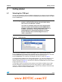
Getting started
4.1
Selecting the COM port
The first step required for using the PLM Demo Kit program is to select the correct COM port
for communication between the PC and the ST7538/40 PLM Demo Board and the ST7 MCU
EVALCOMMBOARD.
Warning:
When running the program for the first time, the user must
perform a Control Register Writing operation before being
able to access the other GUI sections.
This action is mandatory because the only communication
interface available from the MCU on EVALCOMMBOARD to
ST7540 is synchronous, while the default Mains interface of
ST7540 is asynchronous. The only action that can be
performed before a Control Register Writing is a Control
Register Reading, because Control Register Access is
always synchronous.
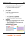
Figure 4.
COM selection
1
Once the correct COM port is selected, the program starts communication with the
EVALCOMMBOARD and automatically recognizes the type of device (ST7538 or ST7540)
on the PLM Board and the firmware revision of the ST7 microcontroller (on
EVALCOMMBOARD). The status bar also displays this data as shown in Figure 3.
If a communication problem occurs during COM selection, e.g. if the Demo Board has not
been properly connected to PC, a message box appears and the user must select the
device to manage (see Figure 5). The user must select the ST7540 device to ensure correct
program behavior (see Note 1).
It is possible to control a maximum of four devices (from COM1 to COM4) using a single
Personal Computer by launching four instances of the program. In order to identify the
instances, a different window background color is used for every COM port. After the COM
selection, the user can access all GUI sections.
13/44
www.BDTIC.com/ST
Getting started
UM0239
Figure 5.
Device selection and communication error during COM selection
COMMUNICATION ERROR
DEVICE SELECTION
Communication errors can occur at any time. The Device Selection message box appears if
an error occurs only during the first COM selection. To ensure reliable communications, a
link status LED is present on the Status Bar as shown in Figure 3.
Note:
4.2
1
If an incorrect device is selected, the user must close and restart the Program in order to
avoid undesired behavior.
Setting the Control Register parameters
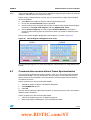
To access to the ST7540 Control Register, click the REG button on the Toolbar. The main
window then displays the Control Register dialog box as shown in Figure 6.
Figure 6.
Control Register window
ST7540 CONTROL REGISTER WINDOW
3
1
1. Control Register Params
Panel
2. WR Control Register String
3. Events Panel
6
4. Write CR Button
5. Read CR Button
2
4
6. Dual channel selection
5
This dialog box enables the user to modify the Control Register parameters.
Certain parameters may only be modified by enabling the Extended Control Register bit of
the Control Register. For more information about the Extended Control Register bit, see
Section 4.2.14: Extended control register on page 19.
14/44
www.BDTIC.com/ST
UM0239
Getting started
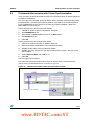
Figure 7.
ST7540 Control Register parameters
ST7540 CONTROL REGISTER PARAMETER PANEL
a
b
c
h
d
e
g
f
j
i
k
l
m
o
p
n
q
r
This section describes each of the Control Register parameters. Table 3 provides a
summary of each parameter, bit-by-bit, as appears in the Control Register string in binary
format from MSB to LSB.
Table 3.
Summary of Control Register parameters
Bits
Parameter
Bits
Parameter
2:0
Carrier Frequency
17
Output Voltage Freeze (1)
4:3
Baudrate
18
Header Recognition (1)
5
Deviation
19
Frame Length Count (1)
6
Watchdog
20
Header Length (1)
8:7
Transmission Timeout
21
Extended Control Register
10:9
Frequency Detection Time
22
Sensitivity Mode
11
Not used
23
Pre-filter
13:12
Detection Method
39:24
Frame Header (1)
14
Mains Interfacing Mode
47:40
Frame Length (1)
16:15
Output Clock
1. Available only when Extended Control Register is enabled.
Note:
Default values listed in this section refer to the ST7540 Power Line Transceiver.
4.2.1
Carrier Frequency
The Carrier Frequency parameter (Bits [2:0]) defines at which center frequency the signal is
transmitted or received across the mains.
If Dual Channel feature is disabled, the Carrier Frequency parameter must be set through
the "ST7540 Control Register Parameter Panel". Otherwise, the "Dual Channel Selection"
panel must be used. For more information, see Section 4.3: Selecting the Dual Channel
option on page 21.
15/44
www.BDTIC.com/ST
Getting started
UM0239
Table 4.
4.2.2
Carrier frequency
Bits 2 to 0 (MSB to LSB)
Value (kHz)
Bits 2 to 0 (MSB to LSB)
Value (kHz)
000
60
100
82.05
001
66
101
86
010
72
110
110
011
76
111
132.5 (default)
Baudrate
The Baudrate parameter (Bits [4:3]) defines the speed of communication.
Table 5.
Baudrate
Bits 4 to 3 (MSB to LSB)
Value (bps)
Bits 4 to 3 (MSB to LSB)
Value (bps)
10
2400 (default)
11
4800
00
01
4.2.3
600
Deviation
The Deviation parameter (Bit 5) defines the frequency difference between the mark and the
space frequency. When set to “0.5”, the difference is one-half the Baud Rate value.
Otherwise, the difference is the Baud Rate value itself.
Table 6.
Deviation
Bit 5
4.2.4
Value
0
“0.5“ (default)
1
“1“
Interfacing mode
The (Mains) Interfacing mode (Bit 14) defines, when transmitting or receiving data across
the Mains, if the timings are managed by ST7540 by means of CLR/T line (Synchronous
mode) or by the host (Asynchronous mode).
In Asynchronous mode, data enter directly in the FSK modulator in Transmission mode and
are sent directly from the demodulator to the RxD line in Reception mode.
In the current software/firmware release, only Synchronous interfacing mode is available.
Due to the fact that Asynchronous Mains interfacing mode is the ST7540 default value, the
user must write at least once to the CR (in Synchronous interface mode) before the GUI will
perform any other action (except CR reading).
Table 7.
Mains interfacing mode
Bit 14
Value
0
Synchronous
1
Asynchronous (default)
16/44
www.BDTIC.com/ST
UM0239
4.2.5
Getting started
Watchdog
The Watchdog parameter (Bit 6) enables the Watchdog function that generates an internal
and external reset when the internal Watchdog timer expires. The Watchdog timer is reset
by applying a negative pulse on pin WD.
Note:
The ST7 MCU Firmware (on EVALCOMMBOARD) automatically provides the Watchdog
Timer Reset.
Table 8.
Watchdog
Bit 6
4.2.6
Value (sec)
0
Disabled
1
1.5 (default)
Transmission timeout
The Transmission Timeout parameter (Bits [8:7]) defines the maximum time of continuous
transmission before a Timeout event occurs. In this case, the transmission is interrupted and
the device is set in RX mode.
Table 9.
4.2.7
Transmission timeout
Bits [8:7]
Value (sec)
Bits [8:7]
Value (sec)
00
Disabled
10
3
01
1 (default)
11
Not used
Detection method
The Detection method (Bits [13:12]) defines the way the modem notifies the presence of a
carrier (CD) or preamble (PD) through the ST7540 CD/PD pin. If the Carrier detection
method is selected, the CD/PD line becomes active when a signal with a harmonic
component close to the programmed Carrier Frequency is detected on the RAI pin. If the
Preamble detection method is selected, the CD/PD line becomes active when a signal with
a carrier modulated at the programmed Baud Rate for at least 4 consecutive symbols
("1010" or "0101") is detected on the RAI pin. If the Detection method is conditioned CLR/T
and RxD signals are enable only when CD/PD line is enable, otherwise CLR/T and RxD are
always enabled.
Table 10.
Bits [13:12]
Detection method
Value
Bits [13:12]
Value
00
Preamble detection without
conditioning
10
Carrier detection without
conditioning (default)
01
Preamble detection with
conditioning
11
Carrier detection with conditioning
17/44
www.BDTIC.com/ST
Getting started
4.2.8
UM0239
Frequency detection time
This parameter (Bits [10:9]) defines the time within which a carrier must be detected across
the Mains before signalling it on ST7540 CD/PD pin. If the Preamble Detection method is
selected, the CD/PD becomes active only if also a preamble is detected.
For more information, see Section 4.2.7: Detection method.
Table 11.
4.2.9
Frequency detection time
Bits [10:9]
Value (msec)
Bits [10:9]
Value (msec)
00
0.5
10
3
01
1 (default)
11
5
Output voltage freeze
The Output Voltage Freeze parameter (Bit 17) turns off the Voltage Control Loop once the
ALC remains in a steady condition for about 3 control loop periods and maintains a stable
condition until the end of transmission.
This function is available only if the Extended Control Register parameter (Bit 21) is
enabled.
Table 12.
Output voltage freeze
Bit 17
4.2.10
Value
0
Enabled
1
Disabled (default)
Output clock
The Output Clock parameter (Bits [16:15]) sets the ST7540 MCLK line frequency as a submultiple of the 16-MHz oscillator frequency or disables the output clock.
Table 13.
4.2.11
Output clock
Bits [16:15]
Value (MHz)
Bits [16:15]
Value (MHz)
00
16
10
4 (default)
01
8
11
Clock OFF
Header recognition
The Header Recognition parameter (Bit 18) enables the hardware recognition of one or
more headers (one 16-bit header or two 8-bit headers depending on the Header Length
parameter setting). Header recognition is signaled by the CD/PD line in different ways
depending on Frame Length Count (bit 19).
Note:
If synchronization software is used, this parameter must be disabled to ensure the correct
behavior of RX sessions.
This function is available only if the Extended Control Register parameter (Bit 21) is
enabled.
18/44
www.BDTIC.com/ST
UM0239
Getting started
Table 14.
Header recognition
Bit 17
4.2.12
Value
0
Disabled (default)
1
Enabled
Frame length count
Frame Length Count parameter (Bit 19) is related to the Header Recognition function.
If enabled, receiving data are put on RxD line and CLR/T becomes active only after a
header recognition and only for the number of (16-bit) data words indicated by the Frame
Length parameter (Bits [47:40]).
Header Recognition is signaled to the host through the CD/PD line that is held low during
RxD and CLR/T activation.
If the Frame Length Count parameter is disabled, the header recognition is signaled by
forcing down the CD/PD line for one CLR/T line period while lines RxD and CLR/T are
always active.
This function is available only if the Extended Control Register parameter (Bit 21) is
enabled.
Table 15.
Frame Length Count
Bit 19
4.2.13
Value
0
Disabled (default)
1
Enabled
Header length
The Header Length parameter (Bit 20) is related to Header Recognition function and defines
the length of the header to recognize (8 or 16 bits).
If an 8-bit header is selected, two headers can be used since the Frame Header parameter
(Bits [39:24]) consists of 16 bits.
This function is available only if the Extended Control Register parameter (Bit 21) is
enabled.
Table 16.
Header Length
Bit 20
4.2.14
Value
0
8 bits
1
16 bits (default)
Extended control register
The Extended Control Register parameter (Bit 21) enables the extended functions: Output
Voltage Freeze and Header Recognition. If enabled, 24 or 48 bits can be transmitted to the
ST7540 (the software always transmits 48 bits when enabled).
19/44
www.BDTIC.com/ST
Getting started
UM0239
Table 17.
Extended control register
Bit 21
4.2.15
Value
0
Disabled (default)
1
Enabled
Sensitivity mode
The Sensitivity Mode parameter (Bit 22) defines the low threshold for the FSK demodulator
block.
Table 18.
Sensitivity mode
Bit 22
4.2.16
Value
0
Normal Sensitivity (500 µVrms) (default)
1
High Sensitivity (250 µVrms)
Pre-filter
The Pre-filter parameter (Bit 23) enables a pre-filter on the Reception path.
Table 19.
Pre-filter
Bit 23
4.2.17
Value
0
Disabled (default)
1
Enabled
Frame header
The Frame Header (Bits [39:24]) defines the Header to recognize when the Header
Recognition function is enabled. It can consist of one 16-bit header or by two 8-bit headers
depending on the Header Length value (Bit 20).
This function is available only if the Extended Control Register parameter (Bit 21) is
enabled.
Table 20.
Pre-filter
Bits [39:24]
MSB--LSB
Default
4.2.18
Value
From 0x0000 to 0xFFFF
0x9B58
Frame length
This parameter (Bits [47:40]) defines the number of data, expressed in 16-bit words (e.g.
Frame Length equal to "1" →16 bits), to send to the Host Controller on the RxD line when
the Header Recognition and Frame Length Count parameters are enabled and a Header
has been detected.
This function is available only if the Extended Control Register parameter (Bit 21) is
enabled.
20/44
www.BDTIC.com/ST
UM0239
Getting started
Table 21.
Frame length
Bits [47:40]
MSB--LSB
Default
4.2.19
Value
From 0x00 to 0xFF
0x80
Limitations on Control Register parameters
Certain parameters are limited during programming because either their functions are not
supported by the tool (software limitations) or because they depend on other Control
Register parameters (hardware limitations). Table 22 lists these limitations.
Table 22.
Limitations on control register parameters
Parameter
Interface mode
Limitation
SW limitation: Only Synchronous Mains interface mode is supported by SW
tool
Output Voltage Freeze HW limitation: Available only if Extended Control Register Bit is enabled
Header Recognition
HW limitation: Available only if Extended Control Register Bit is enabled
Frame Length Count HW limitation: Available only if Extended Control Register Bit is enabled
4.3
Header Length
HW limitation: Available only if Extended Control Register Bit is enabled
Frame Header
HW limitation: Available only if Extended Control Register Bit is enabled
Frame Length
HW limitation: Available only if Extended Control Register Bit is enabled
Selecting the Dual Channel option
Certain ST7540 PLM Demo Boards(a) have the ability to select the central frequency of
external coupling filter between two operating frequencies.
In order to activate this function, the user must select the DUAL CH. check box in the Dual
Channel selection pane, set the correct frequencies for each of the two channels. When
Dual Channel function is enabled, a command of channel selection is transmitted each time
the user pushes the Write Control Register button.
When the Dual Channel feature is enabled, the Control Register is programmed according
to the selected Dual Channel frequency.
a. PLM Eval Boards that support the Dual Channel feature have the suffix "DUAL" (i.e. "EVALST7540DUAL Rev.
x.x")
21/44
www.BDTIC.com/ST
Getting started
UM0239
Figure 8.
Dual channel selection panel
ST7540 DUAL CHANNEL SELECTION PANEL
1
4.4
Monitoring events
By means of Events Panel LEDs it is possible to monitor the status of the Demo Board. The
LEDs represent events occurred during the working session.
Figure 9.
Events panel
EVENTS PANEL
1
The LEDs are updated every time a communication is performed between the software tool
and the Demo Board, except for the Link Monitor LED that it is activated also when the user
modifies a Control Register parameter using the Control Register Parameters Panel. In this
case, the Write Control Register String on the panel no longer corresponds to the ST7540
Control Register. For this reason, the Link Monitor LED is always enabled (red) at first run of
the program.
Table 23 lists possible events.
Table 23.
Summary of events
Event
Reset event
Thermal event
Link monitor
Description
Event occurs when MCU of IBU Communication Board has been reset
Event occurs when a Thermal shutdown event has occurred
Event occurs when:
– Write Control Register String does not correspond to ST7540 Control Register
– A reset or a communication problem event occurs
22/44
www.BDTIC.com/ST
UM0239
Getting started
If a communication problem occurs, a message box describing the issue appears. In this
case, the user must try again to perform the same operation that caused the problem until
no more message boxes appear and the Link Monitor LED becomes green.
Note:
If communication problems persist, the user can reset the microcontroller on
EVALCOMMBOARD by pushing the RES button. After this operation, a Control Register
Writing or a Control Register Reading must be performed in order to avoid undesired
behavior.
4.5
Using the Control Register String
The selected parameter values of the virtual ST7540 Control Register appear in the textbox
at the bottom of the Control Register dialog box (Figure 10) in binary format from MSB to
LSB. When the user modifies or clicks one of the Control Register parameters, the
corresponding bits of the Control Register string become red.
If the Extended Register control bit is set to Enabled, the second part of the Control Register
string (Bits 47 to 24) becomes active and the extended functions are available.
Figure 10. Write control register string and parameters position
CONTROL REGISTER STRING
Sensitivity
Header Rec.
Det. Method
(22)
(18)
(12-13)
Header
Det. Time
Output clock
length
(9-10)
(15-16)
(20)
o
r
Header Length
(40-47)
Note:
k
m
i
Watchdog (6)
Baud Rate
(3-4)
d
b
f
l
h
e
a
Frame Count
(19)
Mains interface
(14)
Tx Time Out
(0-2)
Carrier
Frequency (0-2)
p
Pre filter
(23)
g
n
Extended
Reg. (21)
j
Output Voltage
Freeze (17)
Not Used (11)
c
Deviation (5)
q
Frame Header
(24-39)
When the Extended Register control bit (bit 21) is set to Enabled, the ST7540 accepts 24- or
48-bit CR strings. The “ST7538/40 FSK Power Line Modem Demo Kit” always writes 48 bits
when this bit is enabled.
23/44
www.BDTIC.com/ST
Getting started
4.6
UM0239
Reading/Writing Control Register parameters
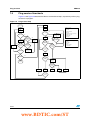
Figure 11 summarizes the Control Register reading/writing procedures with the PLM Demo
Board.
Figure 11. Control register writing/reading procedures
ST7540 CR WRITING/READING PROCEDURES
WRITING
READING
Extended register Enable?
Read always 48 bits from ST7540
(CR Bit 21 equal to 1)?
no
Last 24 bits are significant
(not all “0” or all “1”) ?
yes
Write 24 bits
Write 48 bits
no extended
functions
available
extended
functions
available
no
Get only
first 24 bits
yes
Get all 48
bits
On the Control Register window, click Write CTRL Register to transmit the 24- or 48-bit
Control Register string to the ST7540 PLM Demo Board.
Click Read CTRL Register to read the contents of the Control Register string. This displays
the Read Control Register dialog box shown in Figure 12.
Figure 12. Read CTRL Register dialog box
ST7540 READ CR WINDOW
If no communication issues occur, the Read Control Register string (which is similar to the
Write Control Register string) displays the content of the ST7540 Control Register. Note that
24 or 48 bits are read, depending on parameters Extended Control Register (Bit 21) and
Header Recognition (Bit 18).
Click the Read button in the Read Control Register dialog box to perform a new reading of
Control Register string values. Click the Update Ctrl Panel button to update the Control
Register parameter values with the 24/48 bits that are read. Click Close to close the Read
Control Register dialog box.
24/44
www.BDTIC.com/ST
UM0239
5
Transmission sessions
Transmission sessions
Click TX on the toolbar to open a transmission session and to display the Transmission
Monitor dialog box shown in Figure 13.
Figure 13. Transmission Monitor dialog box
ST7540 TRANSMISSION WINDOW
1
The textboxes display the content to be sent across the Mains in hexadecimal and ASCII
format, respectively.
Transmission methods
Two methods of transmission are available: Sequence and Continuous.
The Sequence method sends the content of textboxes across the Mains for selected
number of times (Nr. parameter) with a delay of 200 ms between transmissions. It is
important to note that each sequence transmitted is a single transmission session to ensure
that no Timeout issues occur if the message to transmit is not too long.
The Continuous method sends the content of the textboxes repeatedly across the Mains in a
single transmission until the transmission is interrupted by the user or by a Timeout event.
Note:
A maximum of 127 bytes can be transmitted to the MCU.
Transmitting data
On EVALCOMMBOARD, the orange DL4 LED is turned on when a transmission begins.
When a Timeout Event occurs, the red DL2 LED is turned on.
Click ON to transmit the content of textboxes (that represents the data to be sent in both
hexadecimal and ASCII format) across the Mains.
Click Load File to load an ASCII or HEX text file in the textbox.
Click Close to close the Transmission Monitor dialog box.
25/44
www.BDTIC.com/ST
Receive sessions
6
UM0239
Receive sessions
Click RX on the toolbar to open a receiving session and to display the Receive Monitor
dialog box shown in Figure 14.
Figure 14. Receive Monitor dialog box
ST7540 RECEPTION WINDOW
RX Textboxes (Hex and ASCII)
Low Sensitivity
Frame synchronization controls
The textboxes display the content of the incoming data in hexadecimal and ASCII format,
respectively. To clear the Hexadecimal and ASCII textboxes, click Reset Scope.
Frame synchronization and Header data
As it is not possible to know when the ST7540 starts to demodulate data incoming from the
mains, a Frame Synchronization feature can be enabled in order to know when the data flow
begins.
If the Frame Synchronization feature is enabled (Frame Sync toggle switch), the data flow
from the ST7540 is filtered from the MCU and the data is sent to the PC only when a header
(defined by the Header parameter) is recognized. This ensures that all following bytes are
correctly sent to PC if the transmitted message is preceded by a preamble (i.e. 0xAAAA or
0x5555) and by a header (i.e. 0x9B58).
To mask the Header, enter the corresponding hexadecimal value in the Mask textbox. This
feature enables the use of less than 16 bits or more than one header. The Masked Header
textbox displays the masked header.
The Data Bytes parameter selects how many bytes the MCU must transmit to the PC after
a header recognition when in Frame Sync mode.
If frame synchronization is not required, the user can switch OFF the Frame Sync feature
and data are sent directly from the ST7540 to the PC. Note that since the first data
demodulation time is unpredictable, byte synchronization is not ensured.
Sensitivity modes
In addition to two sensitivity modes selectable through the Control Register Sensitivity Mode
(see Section 4.2.15: Sensitivity mode), it is possible to force ST7540 sensitivity to the BU
26/44
www.BDTIC.com/ST
UM0239
Receive sessions
level (about 83.5 dBµVrms) by selecting the Force Sens. to BU Level parameter. When
enabled, the TxD line is forced to "1"; thus obtaining a lower sensitivity.
Note:
If synchronization software is used, Control Register Header Recognition (Bit 18) must be
set to "0" in order to have a proper behavior of the RX session. For more information, see
Section 4.2.11: Header recognition on page 18.
Receiving data
On EVALCOMMBOARD, the green DL3 LED is turned on in Receive mode.
Two reception methods are available: Reception with synchronization or Reception without
synchronization depending on the Frame Sync parameter setting.
Click ON to start receiving data. Click Close to stop data reception.
Saving data
In order to save data received from the Mains in a text file (in either hexadecimal or ASCII
format), click Save to File before clicking ON to start receiving incoming data. The
maximum file size allowed is 64 KBytes. To stop saving data, click Stop Saving.
Click Close to close the Receive Monitor dialog box.
27/44
www.BDTIC.com/ST
Ping sessions
7
UM0239
Ping sessions
In order to evaluate the reliability of a communication between two or more devices, a Ping
session can be performed. A ping session consists of a Master that sends a sequence of
messages to one or more Slaves. If the messages are correctly received by Slaves, they are
re-sent to the Master enabling the application to collect a wide variety of statistical data. An
error correction algorithm is also included.
Click PING on the toolbar to open a Ping session. First select Master or Slave to set the
device in the desired mode and to display the corresponding dialog box shown in Figure 15.
Figure 15. Ping windows
ST7540 PING WINDOWS
ER
ST
A
M
SL
AV
E
1
28/44
www.BDTIC.com/ST
UM0239
Ping sessions
7.1
Opening a Ping Master session
7.1.1
Ping Master parameters
As shown in Figure 16, Table 24 following parameters can be selected for the Master device
and the ping session.
Figure 16. Ping Master dialog box
ST7540 PING MASTER WINDOW
MESSAGE
SETTINGS
PING WAIT
TIME & MSG
NUMBER
STATISTICAL
INFORMATION
MEDIUM ACCESS
CONTROL
SETTINGS
CURRENT
MESSAGE
INFORMATIONS
EXECUTE/STOP
BUTTONS
Table 24.
Ping master parameters
Parameter
Description
Message settings
Master address
Defines the Address (from 1 to 255) of the Master device.
Nr. of slave
addresses
Defines the Number (from 1 to 255) of Slave devices. Slave Addresses start
from 1 to Nr. of Slave Addresses.
Nr. of messages
Defines the total number of messages to send to Slave devices. The messages
are numbered from 0 to Nr. of Messages. (Message “0” is used only to reset
Slave statistical data).
Repetition control
Repetition can be used to improve reliability of communication. When enable, if
a message is not Acknowledged it is sent until three times before to consider it
not Acknowledged.
Ping Wait Time and Message Number settings
Wait time
Defines the maximum wait time to obtain a valid response (with a valid
address) from Slave device before considering not Acknowledged the
message. The minimum value that can be selected depends on baud rate
selected according the round trip time of message transmitted.(1)
Messages sent
Defines the number of last message sent. It goes from 0 to Nr. of Messages
and it is updated at every new message sent.
29/44
www.BDTIC.com/ST
Ping sessions
UM0239
Table 24.
Ping master parameters (continued)
Parameter
Description
Medium access control settings
Medium access
control
Defines which type of medium access is used. Choices are “none”, “BU” or
“PD”. In the two last settings, packets are sent only if respectively BU or CD/PD
lines are not active. If “PD” is selected while “Carrier Detection” CR control is
used, content of Control Register is changed in order to select the detection
method to “Preamble detection”.
Max wait slot nr.
If BU or CD/PD lines are actives (depending on Medium Access Control
selected), the Master waits for a time selected randomly between 4ms and
4*Max Wait Slot Nr. ms before to analyze if it is possible to transmit a packet.
Max wait time
Defines the maximum time to wait when “BU” or “PD” Medium Access control
are selected before to transmit the packet. When the Max Wait Time is
elapsed, the packet is transmitted even if BU or CD/PD lines are actives.
Current message settings
Current message
status
Shows information about the acknowledgement of the current message sent.
Last Addressed Slave represents which Slave is the recipient of message.
LEDs show if a message is acknowledged properly (OK), not correctly
acknowledged (No Ack.), if the acknowledged message has errors corrected
by FEC (Master used FEC) or if the acknowledged message has errors not
corrected by FEC (Wrong FCS).
Statistical data display
Statistical data for
Slave
These data are available for each Slave. Enter the name of the Slave device in
Slave Description textbox.
– % OK messages: the total number of messages properly received plus those
corrected through FEC
– Corrected messages: the number of messages corrected through FEC
– KO messages: the total number of messages with wrong FCS plus the
number of message not acknowledged
– Wrong FCS messages: the number of messages with wrong FCS even after
correction
– Not ACK messages: the number of messages not acknowledged
Click Save Statistics to store collected data in a text file.
1. Minimum Wait time values are: @600 bps→300 ms, @1200 bps→150 ms, @2400 bps→75 ms, @4800
bps→40 ms.
7.1.2
Starting a Master Ping session
Click Ping Start to start the ping session. The MCU on EVALCOMMBOARD continuously
transmits the current status of every message transmitted to the PC.
Click Ping Stop to end the ping session.
Click Close to close the Ping Master dialog box.
30/44
www.BDTIC.com/ST
UM0239
Ping sessions
7.2
Opening a Ping Slave session
7.2.1
Ping Slave parameters
As shown in Figure 17, Table 25 following parameters can be selected for the Slave device
and the ping session.
Figure 17. Ping slave window
ST7540 PING SLAVE WINDOW
SLAVE
ADDRESS
MEDIUM ACCESS
CONTROL
SETTINGS
STATISTICAL
INFORMATION
LAST RECEIVED
MESSAGE
INFORMATIONS
EXECUTE / STOP /
CLOSE BUTTONS
Table 25.
Ping slave parameters
Parameter
Description
Slave address settings
Slave address
Defines the Address (from 1 to 255) of Slave device.
Medium access control settings
Medium Access
Control
Defines which type of medium access is used. Choices are “none”, “BU” or
“PD”. In the two last settings packets are sent only if respectively BU or CD/PD
lines are not active. If “PD” is selected while “Carrier Detection” CR control is
used, content of Control Register is changed in order to select the detection
method to “Preamble detection”.
Max Wait Slot Nr.
If BU or CD/PD lines are actives (depending on Medium Access Control
selected), the Slave waits for a time selected randomly between 4ms and
4*Max Wait Slot Nr. ms before to analyze if it is possible to transmit a packet.
Max Wait Time
Defines the maximum time to wait when “BU” or “PD” Medium Access control
are selected before to transmit the packet. When the Max Wait Time is
elapsed, the packet is transmitted even if BU or CD/PD lines are actives.
Last received message information
Last Received
Message
Shows the number of last message received. This field is updated only when
Get statistical Data button is pressed.
31/44
www.BDTIC.com/ST
Ping sessions
UM0239
Table 25.
Ping slave parameters (continued)
Parameter
Description
Statistical data display
The following statistical data are collected:
– OK messages: the total number of messages properly received plus those
corrected through FEC
– Corrected messages: the number of messages corrected through FEC
– RX more than once: the number of messages received more than once
– KO messages: the number of message not received
– Wrong FCS messages: the number of messages with incorrect FCS even
after correction
– Not RX messages: the number of message not received, calculated by
subtracting the number of total message received (both the correct and the
incorrect ones) from the number of last message received (Last Received
Message field)
Click Get Statistical Data to update statistical data. Click Save Statistics to
store collected data in a text file.
7.2.2
Starting a Slave Ping session
Click Ping Start to start the ping session and enable the reception of data.
Click Ping Stop to end the ping session.
Click Close to close the Ping Slave dialog box.
7.3
Ping protocol
The Ping session consists of an exchange of packets between one Master device and one
or more Slave devices. Figure 18 shows the ping message exchange format.
Figure 18. Ping message format
ST7540 PING MESSAGE FORMAT
ORIGINAL MESSAGE
(NOT CODED)
Byte nr.
Field
1
1
receiver
Address
transmitter
Address
3
Message
number
1
2
repetition
FCS field
TRANSMITTED MESSAGE
22 bytes (CODED)
Byte nr.
Field
6
preamble+header
1
1
FEC
1
1
FEC
1
1
FEC
1
1
FEC
1
1
FEC
1
1
1
FEC
1
FEC
1
1
FEC
1
32/44
www.BDTIC.com/ST
UM0239
Ping sessions
When the user clicks PING START, the session begins and the Master sends a series of
packets to one or more Slave devices. All the packets contain the following information:
●
Preamble (0xAAAAAAAA): 4 bytes
●
Header (0x9B58 for Master packets and 0xE958 for Slave packets): 2 bytes
To improve reliability of communications, a FEC algorithm and one redundant byte is used
for each of the following bytes of information:
●
Receiver Address: 1 byte (+ 1 byte for FEC)
●
Transmitter Address: 1 byte (+ 1 byte for FEC)
●
Current Message number: 3 bytes (+ 3 bytes for FEC)
●
Repetition (0x00,0x01,0x02 if the same message has been transmitted once, two or
three times): 1 byte (+ 1 byte for FEC)
●
FCS field, obtained through a calculation of 12 previous bytes: 2 bytes (+ 2 byte for
FEC)
The Slave detects, through the Receiver Address field, if the packet is headed for it or not. If
the message is directed to it, a FCS operation is performed on 12 bytes following the
preamble and the header. The result of calculation is compared with FCS field transmitted
from Master. If the two values differ, an attempt of correction is executed (through FEC
correction code) and a new comparison is performed. If the two FCS fields match, the
message is considered OK from Slave and it is resent to the Master (inverting Master
Address with Slave Address and recalculating FEC and FCS bytes). Otherwise, the
message is considered KO and no response is performed.
An exception occurs when Master transmits the message zero (with Message Number field
0x000000). This message is used to reset the Slave, statistical data collected and no
response to Master is needed.
After a packet transmission, the Master waits (for a time defined in Wait Time in Master
Window) the response from Slave, and if a message headed for it is detected it performs the
same "correctness detection" operation above described in order to consider the message
OK or KO.
Repetition function
To improve the reliability of communications, it is possible to use the repetition function. In
this case, if a response is not detected by Master the packet is sent again for a maximum of
three times before it is definitively considered Not Acknowledged.
Medium access control
A Medium Access Control is also implemented (for both Master and Slave) in order to
prevent two or more devices from transmitting at the same time as described in Table 24 for
the Ping Master parameters and Table 25 for Ping Slave parameters.
Note:
For a low-level description of Ping protocol, please refer to “Power Line Modem Evaluation
FW”.
33/44
www.BDTIC.com/ST
Ping sessions
7.4
UM0239
Ping session flowcharts
Figure 19 and Figure 20 describe the Master and the Slave loops, respectively, while a ping
session is in progress.
Figure 19. Ping master loop
Ping Start
MSG_NUM ‡ 1
SLAVE ADD = 1
MSG_NUM= 0
Ping Master settings:
Create MSG
(MSG_NUM)
•MASTER ADDRESS
•SLAVE NUM
Create MSG (0)
•TOT MESSAGE NUM
YES
•WAIT TIME
MAC enable ?
Wait RAND time
(from 1 to Max
Wait Slot No. * 4 ms)
YES
MAC enable ?
NO
MAC equal to
PD and Control
Register set
to CD?
NO
Transmit
MSG (0)
YES
Slave add. ‡ 1
Repetition
enabled and
< 3 messages
transmitted?
YES
Message
Acknowledged
and Wait Time
not elapsed?
Line busy
and Max Wait Time
not elapsed?
YES
Line busy
and Max Wait Time
not elapsed?
•MAX WAIT TIME
YES
Ping Master current message output data:
•OK MESS.
NO
NO
NO
Slave Add. <
Slave No.?
NO
Set Control
Register to PD
NO
•MAX WAIT SLOT NR.
•REPETITION
Transmit MSG
(MSG_NUM)
YES
•MAC (MEDIUM ACCESS CONTROL)
YES
•CORR. MESS.
•KO MESS.
Repetition
enabled and
< 3 messages
transmitted?
YES
•WRONG FCS MESS.
•NOT ACK MESS.
NO
Master Address
correct ?
Wait RAND time
(from 1 to Max
Wait Slot No. * 4 ms)
NO
YES
Calculate FCS
NO
YES
MSG_NUM <
TOT MSG NUM?
FCS
NO
calculated equal
to FCS
received?
NO
Use FEC and
calculate a
new FCS
YES
Ping Stop
New FCS
equal to FCS
of corrected
message?
NO
YES
SLAVE ADD‡ 1
OK MESS.
CORR MESS.
WRONG
FCS MESS.
MSG NOT ACK
YES
Slave Add. <
Slave No.?
NO
34/44
www.BDTIC.com/ST
UM0239
Ping sessions
Figure 20. Ping slave loop
Ping start
TOT RX MSG = 0
TOT OK MSG = 0
TOT CORR MSG = 0
TOT RX MORE MSG = 0
TOT WR FCS MSG = 0
Ping Slave settings:
FCS
NO
calculated equal
to FCS
received?
•SLAVE ADDRESS
•MAC (MEDIUM ACCESS CONTROL)
Use FEC and
calculate a
new FCS
MAX WAIT SLOT NR.
MAX WAIT TIME
YES
Ping Slave Total Message Data:
Message
detected ?
New FCS
equal to FCS
of corrected
message?
NO
NO
•LAST MSG REC.
•TOT OK MSG
•TOT CORR MSG
YES
•TOT RX MORE MSG
YES
•TOT WR FCS MSG
SLAVE
ADDRESS
correct?
NO
YES
Message
already
received?
YES
YES
Message
already
received?
NO
NO
YES
TOT OK MSG
‡1
TOT RX MORE
MSG ‡ 1
TOT CORR
MSG ‡ 1
TOT WR FCS
MSG ‡ 1
MSG number = 0 ?
NO
Get LAST MSG REC
and create reply message
Calculate FCS
YES
MAC enable ?
MAC equal to
PD and Control
Register set
to CD?
NO
Transmit
message
YES
Set Control
Register to PD
NO
Wait RAND time
(from 1 to Max
Wait Slot No. * 4 ms)
NO
Line busy
and Max Wait Time
not elapsed?
YES
35/44
www.BDTIC.com/ST
Communication session examples
8
UM0239
Communication session examples
This sections provides examples of some of the most common operations that can be
performed with two or more Demo Boards. The operations performed are:
●
Communication session without Frame Synchronization
●
Communication session with Software Frame Synchronization
●
Communication session with ST7540 Frame Synchronization
●
Ping session
8.1
Setup procedure
8.1.1
Required hardware
The following hardware is required for these example sessions:
●
Two EVALCOMMBOARD rev. 1.1 + EVALST7540-1 rev. 2.1 (76 kHz)
●
One PC with two RS-232 ports
8.1.2
Hardware setup
The setup of the communication sessions is common for all tests.
1. Connect the PLM Demo Boards to the EVALCOMMBOARDs.
2. Connect the boards to the two RS-232 PC ports through the serial cables to the PC.
3. Link the PLM Boards to an isolated 110/220V~ Mains voltage.
4. Finally, reset the two EVALCOMMBOARDs by pressing the Reset button.
8.1.3
Software setup
To control two devices at the same time, the user must run two sessions of the program:
1.
Open Start, Programs, ST7538_40 FSK Power Line Modem Demo Kit and click
ST7538_40 FSK Power Line Modem Demo Kit.
2.
Then, select the correspondent COM available for every session (in this example
COM1 for the first board and COM3 for the second board); enabling the GUI to
communicate with each EVAL Board.
Figure 21. Communication setup: COM selection
COM port selection
TOOLBAR enabled
STATUS BAR update
36/44
www.BDTIC.com/ST
UM0239
Note:
Communication session examples
After selecting COM port, the Status Bar is updated showing information about the selected
COM port, SW/FW revisions and the Link status.
Before starting a Communication session, the user must perform a Write Control Register
for the two windows.
3.
Click REG on the toolbar to open the Control Register dialog box.
4.
Ensure that the Dual Channel feature is disabled.
5.
Because only few bits change for the sessions in respect to the default Control Register
parameters, click Read CTRL Register and then Update CTRL Panel.
6.
Set the Carrier Frequency to 72 kHz and the Detection Method to Preamble to
ensure that the incoming data are received only when a preamble is detected across
the Mains.
Now, the two Control Register dialog boxes should appear as shown in Figure 22.
Figure 22. Control Register dialog boxes after setup
COM 1
COM 3
Once the Control Registers are correctly configured, communication can begin between the
boards.
8.2
Communication session without Frame Synchronization
In this example, the board connected to COM1 is used as the Transmitter while the board
connected to COM3 is used as the Receiver. Five messages are transmitted across the
Mains and the receiving method is not synchronized, so incoming data from ST7540 are
sent directly to the PC.
Actions to perform on GUI connected with COM3:
1.
Click Rx on toolbar to open the Rx Monitor dialog box.
2.
Set FRAME SYNC to OFF.
3.
Click ON.
Now the receiving board is waiting incoming data. (It activates itself only when a preamble is
detected across the Mains).
Actions to perform on GUI connected with COM1:
1.
Click Tx on toolbar to open the Tx Monitor dialog box.
2.
Write the preamble "AAAAAAAA" in the hexadecimal textbox.
37/44
www.BDTIC.com/ST
Communication session examples
UM0239
3.
Add the text string “transmission without synchronization” in the ASCII textbox.
4.
Select Sequence Mode and set Nr. to “5”.
5.
Click ON.
Five messages are sent with a temporal distance of 200 milliseconds.
Figure 23. Communication without Frame Synchronization example
COM
COM
1 1
COM33
COM
Synchronized
Message
Synchronized message
In Figure 23 (COM3 section), the five transmitted sequences do not appear to be received
correctly. This behavior is due to fact that the ST7540 starts writing data on the RX line at
different time for every message, because in Synchronous Mode the PLL that provides the
CLR/T signal must reach the lock-in condition.
Lock-in condition can only be reached after an undetermined number of demodulated data
transitions (maximum 5) and during this time one or more bits can be lost. For this reason, if
a sequence of bits that starts like: "1010-1010-1010-1010-…." (0xAAAA… in hexadecimal)
is transmitted, the receiver can only demodulate with correct timings a part of this sequence.
For example, if the first "10101" is lost, the PC will receive the sequence "0101-0101010….." (or 0x55 in hexadecimal). So, even if all bits are correct, byte synchronization is
lost.
Figure 24 shows an example of timing diagram for a baud rate of 2400.
Figure 24. Demodulation timings for RX with preamble detection (@2400 baud)
bit time (0.417ms)
DATA DEMOD.
0 1 0 1 0 1 0 1 0
INTERNAL
SIGNALS
PLL LOCK-IN
PLL lock-in (variable)
preamble detected
CD/PD detection time (1ms)
CD/PD
EXTERNAL
SIGNALS
RxD ACTIVE
RxD NOT ACTIVE
RxD
0
1
38/44
www.BDTIC.com/ST
0
UM0239
8.3
Communication session examples
Communication session with Frame Synchronization
In this example, the board connected to COM1 is the Transmitter while the board connected
to COM3 is the Receiver.
Five messages are transmitted across the Mains and the receiving method includes Frame
Synchronization, so incoming data from ST7540 are supervised by the microcontroller on
EVALCOMMBOARD and only the bits that follow the sequence "0x9B58" ("1001-10110101-1000") are sent to the PC.
Actions to perform on GUI connected with COM3:
1.
Click Rx on toolbar to open the Rx Monitor dialog box.
2.
Set FRAME SYNC to ON.
3.
Write "9B58" in Header textbox and "FFFF" in Mask textbox.
4.
Set Data Bytes to "36"
5.
Click ON.
Actions to perform on GUI connected with COM1:
1.
Click Tx on toolbar to open the Tx Monitor dialog box.
2.
Write the preamble "AAAAAAAA" in the hexadecimal textbox.
3.
Add the header "9B58" in the hexadecimal textbox.
4.
Add the text string "transmission with SW synchronization" (length = 36 bytes) in the
ASCII textbox.
5.
Select Sequence Mode and set Nr. to “5”.
6.
Click ON.
Five messages are transmitted.
Using the Frame Synchronization feature, the user ensures that the transmitted bytes
always arrive synchronized to the PC as shown in Figure 25.
Figure 25. Communication with Frame Synchronization example
COM 1
COM 3
FRAME Header (0x9B58)
39/44
www.BDTIC.com/ST
Communication session examples
8.4
UM0239
Communication session with Hardware Frame
Synchronization
In this example, the board connected to COM1 is used as the Transmitter while the board
connected to COM3 is the Receiver. Five messages are transmitted across the Mains and
the receiving method is synchronized by ST7540 through the Header Recognition function
of the Control Register. This enables incoming data from the ST7540 to arrive already
synchronized to EVALCOMMBOARD and are directly sent to the PC.
Actions to perform on GUI connected with COM3:
1.
2.
Click REG on toolbar to open the Control Register parameter dialog box.
–
Enable Extended Register.
–
Enable Header Recognition.
–
Enable Frame Length Count.
–
Set Header Length Control to "16 bits".
–
Set Frame Header Control to "9B58" (hexadecimal value).
–
Set Frame Length Control to "14" (hexadecimal value equal to twenty 16-bit
words or 40 bytes).
–
Click Write CTRL Register.
Click Rx on toolbar to open the Rx Monitor dialog box.
–
Set Frame Sync to OFF.
–
Set Force Sens. to BU Level to OFF.
–
Click ON.
Actions to perform on GUI connected with COM1:
1.
Click Tx on toolbar to open the Tx Monitor dialog box.
2.
Write the preamble "AAAAAAAA" in the hexadecimal textbox.
3.
Add the header "9B58" in the hexadecimal textbox.
4.
Add the text string "transmission with ST7540 synchronization" (length = 40 bytes) in
the ASCII textbox.
5.
Select Sequence Mode and set Nr. to “5”.
6.
Click ON.
Five messages are transmitted.
Using the Hardware Frame Synchronization feature, the user ensures that the transmitted
bytes always arrive synchronized to the PC as shown in Figure 26.
40/44
www.BDTIC.com/ST
UM0239
Communication session examples
Figure 26. Communication with Hardware Frame Synchronization
COM 1
COM 3
FRAME Header (0x9B58)
SW sync. OFF
8.5
Ping session
In this example, the board connected to COM1 is the Master while the board connected to
COM3 is the Slave. 100 messages are exchanged from Master to Slave and statistical data
(as for Master as for Slave) are saved in two text files.
Actions to perform on GUI connected with COM3:
1.
Click PING on toolbar to open the Ping dialog box.
2.
Select Slave and click OK.
3.
Set Slave Address to "1".
4.
Write "Ping session nr. 1" in Slave Description field.
5.
Set Medium Access Control to "PD", Max Wait Slot Nr. to "10" and Max Wait Time
[ms] to "1000".
6.
Click Ping Start.
Actions to perform on GUI connected with COM1:
1.
Click PING on toolbar to open the Ping dialog box.
2.
Select Master and click OK.
3.
Set Master Address and Nr. of Slave Addresses to "1".
4.
Set Nr. of Messages to "100" and Repetition Control to "3".
5.
Set Wait Time [ms] to "255".
6.
Set Medium Access Control to "PD", Max Wait Slot Nr. to "10" and Max Wait Time
[ms] to "1000"
7.
Click Ping Start to start the ping session.
Saving statistics
When all messages are transmitted, on the Ping Master dialog box click Save Statistics
and selecting the path and the name of the text file (in this case "Ping session nr. 1
(Master).txt").
41/44
www.BDTIC.com/ST
Communication session examples
UM0239
To save Slave statistics, click Get Statistical Data (to update the statistics), click Save
Statistics and selecting the path and the name of the text file (in this case "Ping session nr.
1 (Slave).txt").
Figure 27. Ping master session and save statistics
Figure 28. Ping slave session and save statistics
42/44
www.BDTIC.com/ST
UM0239
9
Revision history
Revision history
Table 26.
Revision history
Date
Revision
24-Jul-2006
1
Changes
Initial release
43/44
www.BDTIC.com/ST
UM0239
Please Read Carefully:
Information in this document is provided solely in connection with ST products. STMicroelectronics NV and its subsidiaries (“ST”) reserve the
right to make changes, corrections, modifications or improvements, to this document, and the products and services described herein at any
time, without notice.
All ST products are sold pursuant to ST’s terms and conditions of sale.
Purchasers are solely responsible for the choice, selection and use of the ST products and services described herein, and ST assumes no
liability whatsoever relating to the choice, selection or use of the ST products and services described herein.
No license, express or implied, by estoppel or otherwise, to any intellectual property rights is granted under this document. If any part of this
document refers to any third party products or services it shall not be deemed a license grant by ST for the use of such third party products
or services, or any intellectual property contained therein or considered as a warranty covering the use in any manner whatsoever of such
third party products or services or any intellectual property contained therein.
UNLESS OTHERWISE SET FORTH IN ST’S TERMS AND CONDITIONS OF SALE ST DISCLAIMS ANY EXPRESS OR IMPLIED
WARRANTY WITH RESPECT TO THE USE AND/OR SALE OF ST PRODUCTS INCLUDING WITHOUT LIMITATION IMPLIED
WARRANTIES OF MERCHANTABILITY, FITNESS FOR A PARTICULAR PURPOSE (AND THEIR EQUIVALENTS UNDER THE LAWS
OF ANY JURISDICTION), OR INFRINGEMENT OF ANY PATENT, COPYRIGHT OR OTHER INTELLECTUAL PROPERTY RIGHT.
UNLESS EXPRESSLY APPROVED IN WRITING BY AN AUTHORIZED ST REPRESENTATIVE, ST PRODUCTS ARE NOT
RECOMMENDED, AUTHORIZED OR WARRANTED FOR USE IN MILITARY, AIR CRAFT, SPACE, LIFE SAVING, OR LIFE SUSTAINING
APPLICATIONS, NOR IN PRODUCTS OR SYSTEMS WHERE FAILURE OR MALFUNCTION MAY RESULT IN PERSONAL INJURY,
DEATH, OR SEVERE PROPERTY OR ENVIRONMENTAL DAMAGE. ST PRODUCTS WHICH ARE NOT SPECIFIED AS "AUTOMOTIVE
GRADE" MAY ONLY BE USED IN AUTOMOTIVE APPLICATIONS AT USER’S OWN RISK.
Resale of ST products with provisions different from the statements and/or technical features set forth in this document shall immediately void
any warranty granted by ST for the ST product or service described herein and shall not create or extend in any manner whatsoever, any
liability of ST.
ST and the ST logo are trademarks or registered trademarks of ST in various countries.
Information in this document supersedes and replaces all information previously supplied.
The ST logo is a registered trademark of STMicroelectronics. All other names are the property of their respective owners.
© 2006 STMicroelectronics - All rights reserved
STMicroelectronics group of companies
Australia - Belgium - Brazil - Canada - China - Czech Republic - Finland - France - Germany - Hong Kong - India - Israel - Italy - Japan Malaysia - Malta - Morocco - Singapore - Spain - Sweden - Switzerland - United Kingdom - United States of America
www.st.com
44/44
www.BDTIC.com/ST