1
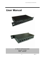
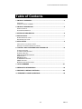
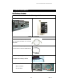
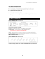
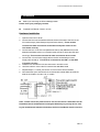
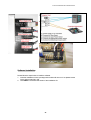
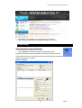
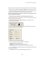
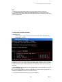
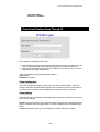
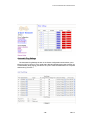
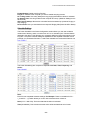
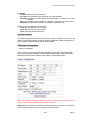
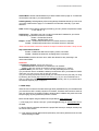
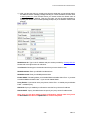
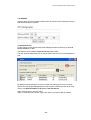
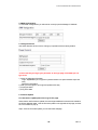
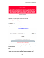
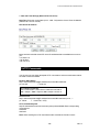
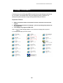
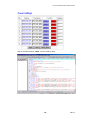
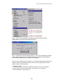
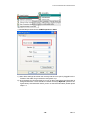
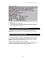
IP BOOT MANAGER 9280 USERS MANUAL
IP Boot Manager 9280
User Manual
IP BOOT MANAGER 9280 USERS MANUAL
User Manual
IP BOOT MANAGER 9280
Version:V1.00
Date:2008.04
-1-
VER. 1.0
IP BOOT MANAGER 9280 USERS MANUAL
Notice:
1. Any modification without the authorization of the manufacturer will void the
warranty of the product
2. This device has been FCC and CE certified and should be used under
normal conditions to prevent damage and interference to the device.
Important:
1. We are not responsible for any damages caused by misuse of the
device or use in an inappropriate form or environment.
2. Do not shake or use the IP Boot Manager in a shaking manner.
3. If the 9280 is defective after purchasing, please contact your local dealer to
get after sales service. Please do not disassemble the product in any way,
shape, or form for this may cause your warranty to void.
Copyright:This manual prohibits any form of copy or reproduction without the
consent of the manufacturer.
Trademark:The trademarks and names that are used in this manual are
recognized by their respected owners
Warning:You will not be notified of any new hardware updates.
-2-
IP BOOT MANAGER 9280 USERS MANUAL
Table of Contents
1. PRODUCT OVERVIEW ...............................................................................................4
FEATURES .........................................................................................................................
INTRODUCTION OF THE 9280 .............................................................................................
2. PRODUCT DESCRIPTION..........................................................................................5
PRODUCT SPECS ..............................................................................................................
SYSTEM REQUIREMENTS ...................................................................................................
3. INTERFACE DESCRIPTION .......................................................................................6
4. INSTALLATION ............................................................................................................7
HARDWARE INSTALLATION .................................................................................................
SOFTWARE ISTALLATON .....................................................................................................
5. INTIAL SETUP..............................................................................................................9
INITIAL SETUP TO CONTROL LAN PC....................................................................................
SETTING UP LAN PC FOR SAFE SHUTDOWN .......................................................................
6. CONTROL AND CONFIGURATIONS THROUGH IE............................................ 12
CONTROL SETTINGS ...........................................................................................................
AUTOMATIC PING SETTINGS ...............................................................................................
SCHEDULE SETTING...........................................................................................................
9280 SYSTEM CONFIGURATION .........................................................................................
9280 IP SETUP..................................................................................................................
DDNS SETTINGS ...............................................................................................................
IP SERVER FUNCTIONS ...................................................................................................
SNMP SETTINGS...............................................................................................................
NTP SETTINGS AND FEATURES .........................................................................................
7. HTTP COMMANDS ................................................................................................. 21
8. WEBPAGE CUSTOMIZATION ................................................................................ 22
9. RESTORE TO DEFAULT SETTINGS ..................................................................... 26
10. FREQUENTLY ASKED QUESTIONS ................................................................... 26
-3-
VER. 1.0
IP BOOT MANAGER 9280 USERS MANUAL
1. Product Overview
The IP Boot Manager 9280 is a server / cpu management hardware that helps maintain the
stability and integrity of the computers that is it managing. It features the ability to Turn off,
Turn on, Reset, Auto-ping, schedule daily server maintenance, and etc. With no limitations
to the type of PC’s that can be used, and also no additional software installation needed, this
device allows you to manage up to 8 separate PC’s from anywhere in the world as long as
you have internet connection. The IP Boot Manager 9280 gives you the flexibility to be
anywhere and yet still have access to your servers or your client’s servers. Giving you time
flexibility, lowered costs (from overheads), and access from anywhere this device is a must
have in any server room.
Features:
1. Built in web-server no PC is needed.
2. Built in HTTP Internet browsing interface. No special software is needed to use, only
major internet web browsers such as Internet Explorer and Netscape.
3. Control the Turn off, Turn on, and Reset of up to 8 separate PC’s or servers
4. Network Support:HTTP, SMTP, Internet, Fixed IP, DHCP, DDNS, LAN, Virtual IP.
5. Secure Password Installation that is easy to install or updated.
6. Serial Communication Port to support real time status of the 9280.
7. LED lights that show the connection status of each PC.
8. Resistant High-Voltage design is not leakage, non flammable material.
9. IP 9XXX Series can be combined or used independently together
10. Scheduler: Allows you to set a specific time or date to run a turn off, turn on, and reset of
your PC’s
11. NTP Support, allows you set the time and synchronize the device with a computer on
the net network
-4-
IP BOOT MANAGER 9280 USERS MANUAL
2. Product Descriptions
9280 Package Contents
Includes the following main items:
IP Boot Manager 9280 Base Unit
8 PCI Cards that go into Servers
Cables and Accessories
Internet Cable (1meter):
For Connecting the Base unit to Router,
Hub, or PC.
Cat5e Cable (5meter) x 2:
Connect the PCI Card to the 9280 Base unit
DC Adapter (12V):
DC adapter for Powering up device
4 Pin and 2 Pin Connectors:
(Black and White)
(Red and Black)
-5-
VER. 1.0
IP BOOT MANAGER 9280 USERS MANUAL
CPU Minimum Requirements
CPU Processor: The same as or above a Intel Pentium III or AMD Athalon
Operating Systems: WINDOWS Operating Systems (IE5.0+SPI) & LINUX
Memory Requirements 64MB or More
Supports Direct Draw Graphics Card
RJ45 LAN & Internet HUB & Switch
Internet (For remote access) or Ethernet Network (Internal Network use) with some
type of Internet connection, (i.e. ADSL, Cable, Dial up or any other forms of Internet
service)
3. Interface Descriptions
IP BOOT MANAGER 9280 Front Panel View
Picture is Describe from Left to Right:
DC 12V: DC 12 Volt input – Found on both POE and Non POE Models
POE NETWORK:Connect the RJ45 or POE cable to this section.
* Note: POE is only available on the POE models
RESET:Press and Hold for 3-5 to reset device back to manufacturer default settings
PC LINK STATUS:Provides information on whether the servers / Cup’s are connected
CONSOLE-RS232: Internal Debugging Purposes
PWR:Power Status Indicator
IP BOOT MANAGER 9280 Rear Panel View
Connect up to 8 PC’s / Servers using regular RJ45 cables which are connected to the PCI
card that is installing into the PC’s Servers to control the Turn off, Turn on, and Rest.
-6-
IP BOOT MANAGER 9280 USERS MANUAL
4. Installation
Before you start using the IP Boot Manager 9280
Please check your packaging contents:
Prepared POE Router / Router / or Hub
Hardware Installation
1
Open the main CPU / Server
2
Connect the Pins from the Reset and Power Switch of the case to the Pins on the
PCI card that says (Case Reset) and (Case Power Switch) * These must be
connected to make sure that the reset buttons and power switch on the
case works correctly.
3
Connect the Pins on the PCI card (MB Power Switch) and (MB Reset Pin) to the
Motherboard (Please refer to your mother boards manual on where the reset pins
should go) *This must be connected to make sure that the device works
4
Connect the 4 Pin 5V Power supply cable to the PCI card where the Power
Supply cable should go. *This must be connected for the LED’s on the 9280
5
6
to function correctly
Install the PCI card into the PCI Slot and screw in and fix the card
Use RJ45 cable to connect the PCI card and the 9280 Bare board
7
Repeats Steps 1-7 until all your servers or CPU have the device installed.
8
Now that all the Cpu’s and Servers are connected to the 9280. Make sure that the
9280 is connected to a router, hub, or modem.
Note: * Please refer to the picture below to see how the device is attached to the PC.
Remember that all motherboards are designed differently so you may have to refer
to your motherboards manual to find where the Power and Reset switch connect to.
-7-
VER. 1.0
IP BOOT MANAGER 9280 USERS MANUAL
Software Installation
Please follow the steps below to install the software.
1. Insert the Installation CD in the package and windows will auto-run. If not please browse
for the Autorun.html file in CD.
2. Click IPEdit in the downloads section of the installation CD
-8-
IP BOOT MANAGER 9280 USERS MANUAL
3. Save IPEdit to your desktop or any other place of your choosing
4. After you have saved it onto your desktop and double click to run it.
5. Initial Setup
Initial Setup Through the Ethernet
1. . Open “IPEdit.exe”. Make sure that the IP Boot Manager 9280
is properly turned on and there is an Ethernet connection from the RJ45 cable.
In the local devices section of IPEdit all products under the same subnet network will appear.
Please refer to (Figure 1.1) below:
(Figure 1.1 IPEdit)
-9-
VER. 1.0
IP BOOT MANAGER 9280 USERS MANUAL
IPEDIT will search and display all IP Products 9XXX series under the same local Ethernet.
The default name for the IP Boot Manager 9280 is “IP9280” Please refer to (Fig. 1.2 above).
1. Double click and highlight your IP Boot Manager 9280 device. The default device name
and IP/Network settings will all be displayed on the right hand side of IPEdit.
Make sure that the IP Address of your 9280 is setup on the same subnet network as
your PC’s (Subnet mask, Gateway)
*
Represents that your 9280 does not match the gateway of your router.
(E.g. If the Default Gateway of your computer is 192.168.1.1 The IP Address of your 9280
will need to be set up to 192.168.1.XXX.)
2a. Automatically Detect Network settings (Please go to 2b. for steps on how to
manually enter network settings)
a.) Click on the REF button to the right of IPEdit
b.) Please wait a few seconds while IPEdit detects your network settings. Then click the
Apply button to apply the new network settings
2b. Manually enter network settings In Ipedit:
a.) You can manually enter the networks settings for the following:
The name: (please use numbers or letter)
Gateway IP: (The default gateways IP can be found using
IP Address: (please set in the same subnet as your PC) in the text windows.
b.) Then click Submit after the settings have been selected. Wait about 20 seconds for the
new settings to be updated.
c.) Click Rescan, and the new device settings will display in text window.
- 10 -
IP BOOT MANAGER 9280 USERS MANUAL
Note:
1.) Make sure the RJ45 network cable is connected and the 9280 is powered on.
2.) * The default IP address of the 9280 is 192.168.10.100. If you cannot get into the
webpage of the 9280, please make sure to set subnet of the IP Power 9280 to match with
your PC Subnet Mask.
To obtain the IP information manually:
In Windows Go to:
a.) Start Run type in “cmd”
b.) Now type in “ipconfig”
Hit enter and the MS –DOS window will open,
The last set of numbers of the IP address can be any number between 1~254, but cannot
be same as your PC, hub, router or any device in the network. If using in any PC, just use
HUB and type the 192.168.0.100 in Browser or use “IPDdit.exe “ then you can get in the
web page.
* Same SUBNET: The first 3 sections of IP address is same - XXX.XXX.XXX.abc. The part
of XXX must be the same.
(E.g. One computer with the IP address of 192.168.1.100, while another computer with an
IP address of 192.168.1.123 are IP's in the same subnet.)
5 .The default username and password of IP Power 9280 are:
- 11 -
VER. 1.0
IP BOOT MANAGER 9280 USERS MANUAL
Username: admin
Password: 12345678
6. Control and Configurations Through IE
Two methods for entering the web server:
1.) Open IPEdit.exe and in the local devices section double click on your device. This will
open up internet explorer and you will be prompted for your login and password.
2.) Open up Internet Explorer and type in the IP address of your device. Then you will be
prompted for your login and password.
*Note: The default login and password for the 9280 is
Login: admin
Password: 12345678
Power Configuration
The Power Configuration allows you the user to go into the Power Settings, Auto Ping
Settings, and Power Schedule Settings pages. From here this is where you will be able to
control the power, maintain, and schedule power routines for your PC’s / Servers.
Power Settings
The Power settings in the Power Configuration section allows you to Rename your devices,
Power on/off, or Reset
Rename: This section allows you to Change the name of your device. Just type in the name
that you would like and hit the apply button. To return to default name hit the default name
button
Control: This section allows you to manually Power On/Off or Reset your device
- 12 -
IP BOOT MANAGER 9280 USERS MANUAL
Automatic Ping Settings
The Automatic Ping Settings function in the Power Configuration section allows you to
keep your CPU’s / Server in a very good state. With this watchdog technology it allows you
to automatically keep pinging your Servers or Cpus to make sure that there is no computer
that has hung or frozen. I
- 13 -
VER. 1.0
IP BOOT MANAGER 9280 USERS MANUAL
Enable/Disable: Enable Auto Ping Function
Ping IP: IP Address of the computer you want to enable auto-ping function
No. of Ping retries: How many attempts to retry pinging before Device Action is activated
PC Startup Time: How long it takes for the computer to boot up. (Minimum Setting here is
90 seconds)
After Device Startup: What action to do after Device has started up (Continue Pinging or
Stop Pinging)
Device Action: How you want the device to respond if Pinging fails (Power On/Off or Reset)
Schedule Settings
The Power Schedule in the Power Configuration section allows you, the user to select a
certain time of the day, week, or month to turn off / on or reset the Cpu’s / Servers that are
attached to the device. This will keep your computers stable and clear used memory in the
long term. The power schedule settings is separated into two separate schedules. Power
schedule 1 is composed of Devices 1-4 and Power schedule 2 is composed of Devices 5-8.
The Power Schedule(s) are composed 4 separate fields Date, Time, Frequency, and
Action.
Note:
Each PC has 2 separate Schedule settings. For Example: There is a schedule for PC –
1_A and PC – 1_B which allows you to turn off the device and turn it back on.
Date (YYYY - MM - DD): This is the date that the action is activated
Time (HH:MM:SS): This is the time that the action will be activated use 24 hr format
- 14 -
IP BOOT MANAGER 9280 USERS MANUAL
Frequency:
Disable: Disables the Power Schedule
Just Once: Only activates Power Schedule on the date specified
Everyday: Activates the Power Schedule Everyday Monday – Sunday from the date
specified
Mon – Fri: Activates Power Schedule from Monday – Friday from the date specified
Weekend: Activates Power Schedule on Saturday and Sundays only
Action: Action is separated into 3 parameters
Power On: This field turns on the device
Power Off: This field turns off the device
Reset: This field just resets the device
System Settings
The System Settings section is where you the user would go to configure your device. In this
section you will find the setting controls for System Configuration, DDNS Configuration, IP
Server, SNMP, Password Change, and Firmware Update.
9280 System Configuration
1. System Configuration:
In this section you can manually setup the IP Address of your 9280. This settings page
allows you to setup the IP Address, Subnet Mask, Default Gateway, DNS, DHCP Client,
BEEPER, Http Command Verification, Device Name, and Release Version.
Note: * All of the basic IP address settings can also be setup using IPEdit. Including the IP
Address, Subnet Mask, Default Gateway, and Device Name.
IP Address: In this section use either the IP Address given by your router or a IP address
that is provided by your ISP if you are directly connecting the unit
- 15 -
VER. 1.0
IP BOOT MANAGER 9280 USERS MANUAL
Subnet Mask: Use the Subnet Mask that you desire. Please refer to page 10 “To obtain the
IP information manually” if you need reference
Default gateway: Default gateway refers to the gateway IP address that lets you connect to
your router. Please refer to page 10 “To obtain the IP information manually” if you need
reference
DNS: Please use the DNS IP Address provided by your ISP (Taiwan Companies are allow
to use 168.95.1.1)
DHCP Client: This allows your hub or router to provide the IP address for your device
automatically. By default this function is enabled.
Enable – Enable DHCP server
Disable – Disable DHCP server
Beeper: Enable – Enable beep sounds when commands are sent or activated
Disable – Enable beep sounds when commands are sent or activated
*Each command that is sent to the 9280 if the beeper is enabled will create a “beep” sound
Http Command Verification:
Enable – Enables the 9280 from accepting DHCP commands
Disable – Disables the 9280 from accepting DHCP commands
Device Name: Gives the device a name, which also allows for easy searching in the
network and IPEdit.
Reminder:
1) IP Address Format: xxx.xxx.xxx.xxx:yyyyy
xxx.xxx.xxx.xxx: Resembles the format of the IP Address
yyyyy: Is the port number of the device which ranges from (1~32767).
2) Subnet Mask: (xxx.xxx.xxx.0 ~ xxx.xxx.xxx.254) Can Range from 0~254.
3) If your DHCP client is enabled the default port will be 80. But if you disable the DHCP
client then you can set your own IP and port number
4) If you are using a port other than port 80 you must also enter the port that you using
by following this format (http://xxx.xxx.xxx.xxx:yyyyy). Or you can use IPEdit.exe to
help you setup the virtual IP Address so you can just directly click on your device and
the Internet Explorer page will appear.
2. DDNS Setup
When the user connects to the Internet through ADSL (PPPOE Service), the IP address that
you receive from ISP is usually a dynamic IP Address. Therefore when someone wants to
visit your device they are usually not able to because the IP Address is dynamic and it will
keep changing. By using DDNS this problem is solved.
Below we will explain using the DDNS service provided by www.dyndns.com:
1.) First, apply for a domain name (Ex. [email protected]) in www.dyndns.com for
the 9280.
2.) Set the domain password and select the proper DNS server (for example, dnsdojo.net)
for domain name resolve.
3.) Then input the Domain Name Server (host name), user name, password, and, etc in the
DDNS webpage of 9280.
- 16 -
IP BOOT MANAGER 9280 USERS MANUAL
4.) After you have set every up correctly every time the 9280 start or user selects submit,
the 9280 will send a message package including its current IP address, domain name
to www.dyndns.com, then the DNS server you choose will link the domain name of
9280 to its current IP address. That way the visitor can visit the 9280 webpage by
inputting the domain name of 9280 (abcdefg.dnsdojo.net) in the address column of the
browser.
DDNS Server IP: Type in the IP Address and port number provided by www.dyndns.com
Please refer to the figure above for reference.
Your Domain: Please type in the domain name that you have chosen to use.
DDNS UserName: Enter your DDNS User Name here
DDNS Password: Enter your DDNS password here
Enable DDNS: This setting allows you to enable DDNS or disable. Select True – If you want
to enable DDNS and Select False – If you want to disable DDNS
Proxy Enable: If you need to use a proxy Server, Select True – to enable proxy and Select
False – to disable proxy.
PROXY IP: If proxy is enabled you will need to enter the Proxy Servers IP Address
PROXY PORT: If proxy is enabled enter the port of your proxy server IP Address here
Note: Once you are done setting up these configuration settings make sure you hit
the Save Button and then the Update Now to confirm completion
- 17 -
VER. 1.0
IP BOOT MANAGER 9280 USERS MANUAL
3. IP SERVER
IP Server gives the user the ability to easily search for a device name rather than a long IP
Address that is easy to forgotten.
To Enable IP Server:
Go to IP Server on the Left hand side of the Webpage and then make sure you have IP
Server On/Off set on “On”.
The default IP server Address is 220.135.169.136 and provided.
The user can also setup his/her own IP Server system and use his or her own address as
well.
By setting the server address in IP server of advanced setup page, the user can easily
search for his/her IP Boot Manager 9280 on internet just by searching for the name of the
device. The default IP address of IP server is 220.135.169.136.
Step1: Click the green “connect” button
Step2: In the device name section: Type in the name of your device (Min of 3 letters)
- 18 -
IP BOOT MANAGER 9280 USERS MANUAL
4. SNMP Configuration
To use SNMP configurations you will need to correctly input the Manager IP Address.
5. Change Password
Use these directions to learn how to change your password back to factory default
*In the event that you forget your password. In the login page of the 9280 you can
type in the
1.) Open the webpage of the 9280
Login: “super user” (do not type the quotes and there is a space between super and
user)
Password: leave blank
2.) After you have typed in your login and password hit okay
3.) Unplug the 9280
4.) Plug in the 9280
6. Firmware Update
If no firmware to update please do not go to this page.
When there a new firmware to update, the user will get additional functions that is created for
the IP Boot Manager 9280. Click the firmware update on the right side of the page; and wait
for a new window to pop up.
Step1: Click the “firmware update” you will see follow webpage:
- 19 -
VER. 1.0
IP BOOT MANAGER 9280 USERS MANUAL
Note: Do not click “update“ if there is no firmware file to update .
Step 2: Click The Continue button to continue to the next page
Step 3: Click update button, the following window will pop up.
Step 4: Click the Brower button to find the corresponding update file (you can download it
from our web site or ask it from the dealer), then click Update button to start update
firmware. When the update is finished, you must wait one minute before you restart the IP
Boot Manager 9280.
Note:
* Before running the online update program, please make sure that the TCP port is
set to 80,or the online update may fail.
* Please check with your reseller /distributor / importer for the update news.
- 20 -
IP BOOT MANAGER 9280 USERS MANUAL
7. Date and Time Settings (Network Time Protocol)
Date Time: Enter the correct Date (YYYY – MM – DD) and the Correct Time HH:MM:SS
(Please use a 24 hour format)
NTP Server IP Address:
Below we have included some NTP server IP addresses that are available at not cost to
you:
131.246.9.116
139.18.25.34
128.176.191.9
7. HTTP Commands
You the user can use these developed HTTP commands to achieve certain tasks without
the need to enter the website:
Read PC State Status:
http:// username:password@IP Address/Set.cmd?CMD=GetPower
(0: CPU Off
1: CPU On)
Ex. Output will look like:
P61=1,P62=0,P63=1,P64=0,P65=1,P66=0,P67=0,P68=0
P61 = Output 1, P62 = Output 2, P64 = Output 4 and so on.
Set PC Power:
http:// username:password@IP Address/Set.cmd?CMD=setPower+p1=0/1
(0:Reset
1:Power ON/OFF)
HTTP Command Syntax:
http://IP Address/Set.cmd?user=usename:pass=passwordCMD=Enter corresponding
command line.
GetPower
SetPower
Note: When entering the HTTP Commands make sure that the format is correct.
- 21 -
VER. 1.0
IP BOOT MANAGER 9280 USERS MANUAL
8. Webpage Customization
Customer can use our Web page SDK to amend the word and background pictures
for your 9280. If not familiar html coding and webpage design, please do not
attempt this portion because it may cause problems with your device.
Important Notice:
1. Make sure that the number of characters for the file name does not exceed the
original
2. Do not change the structure of webpage – you can only change the pictures and
the background.
3. The webpage only supports HTML code.
Step 1: Open the 9280 Webpage SDK file , and choose the webpage that you plan to
change.
For example: web page “ipcontrol“ html file
- 22 -
IP BOOT MANAGER 9280 USERS MANUAL
Step 2: Save file format as “UNIX”: Choose “DOS to UNIX”
- 23 -
VER. 1.0
IP BOOT MANAGER 9280 USERS MANUAL
Step 3:Once you are completely done editing the HTML file open the program
“Make9280Html” and hit the button “Make Html Patch”:
Step 4:There will be a new file “Update_2008-01-11.bin” which is the BIN file include the
amend webpage. Please refer to the update procedure to update the firmware BIN file.
Please note the Update procedure must be done in port 80.
After you have updated the new firmware if you are still having problems finding the IP
Address, please use the RS232 interface and connect a computer with the 9280.
Please refer to the following steps:
1. Unplug the 9280
2. Connect the RS232 cable from the 9280 to the (Com 1 Port) of the computer
3. Open “Hyper terminal” located at Start
All Programs
Accessories
Communications Hyper Terminal.
- 24 -
IP BOOT MANAGER 9280 USERS MANUAL
4.) Set the Bits per second in the COM1 Properties to 19200
5.) After all the settings have been set correctly and the com1 port is plugged into the
RS232 of the 9280, Plug in the device and power it up.
6). Once the device is connected look for your IP on the screen where the information is
being transferred to. There should be a section that says MyNowIP: (Refer to the
figure below) XXX.XXX.XXX.XXX If you do not see that information please repeat
steps 1-5
- 25 -
VER. 1.0
IP BOOT MANAGER 9280 USERS MANUAL
7.) Type this IP Address into Internet Explorer which will let you access the devices web
browser
8.) Try re-updating the new firmware now.
9.) If for some reason you are not successful, please check to see if the bin file is too big.
If you need to change the firmware back to original factory default please use
the provided bin file V1.22 in the SDK.
8. Reset to Manufacturers Default Settings
To Reset the Device back to Manufacturer default settings please hold down the reset
button for about 5-7 seconds and then release. Afterwards, please unplug the device and
plug it back in.
9. Frequently Asked Questions (F.A.Q)
Q1: I forgot the password and can not enter the administration page now, what can I do?
A1: Use username "super user" when log in webpage and then click "OK" unplug
the device for few second and then plug it back in. 9280 will to set back to default
password. (There is space between super and user.)
Q2: Why does the on/off operation can not work immediately?
A2: If you operate the IP Boot Manager 9280 in a LAN environment, the operation will work
immediately and smoothly. But ff you operate it through the Internet, the response time
depends on the situation of the network and the speed of your internet.
- 26 -