1
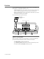
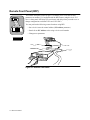
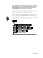
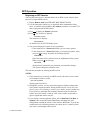
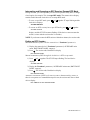
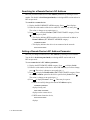
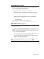
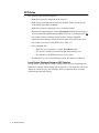
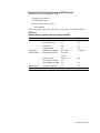
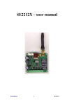
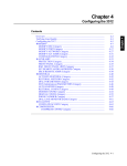
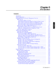
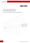
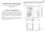
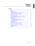
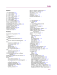
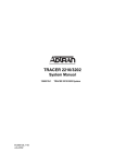
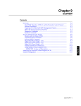
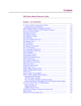
Chapter 3
Contents
Overview........................................................................................................
Light-Emitting Diodes (LEDs) .....................................................................
Menu Structure .............................................................................................
Default Display .........................................................................................
Control Keys .................................................................................................
Alphanumeric Entry ..................................................................................
Remote Front Panel (RFP).............................................................................
RFP Operation ..........................................................................................
Beginning an RFP Session ...................................................................
Interrupting and Resuming an RFP Session: Escape-RFP Mode ........
Ending an RFP Session.........................................................................
Searching for a Remote Device’s NC Address..........................................
Setting a Remote Device’s NC Address Parameter ..................................
RFP and Restoral Operation......................................................................
Automatic Initiation and Termination of Restoral ...............................
Manual Initiation and Termination of Restoral.....................................
RFP and Network Management ...............................................................
RFP and Link Problem Determination Aid (LPDA) ................................
RFP Rules .................................................................................................
Local Device Displays During an RFP Session ...................................
Remote Device Displays During an RFP Session ................................
3-2
3-3
3-4
3-4
3-5
3-5
3-6
3-8
3-8
3-9
3-9
3-10
3-10
3-11
3-11
3-11
3-11
3-11
3-12
3-12
3-13
The Front Panel 3-1
Chapter 3
The Front Panel
Overview
You can configure and operate all functions of the 3512 DSU/CSU through the front
panel (Figure 3-1). This chapter introduces you to:
• Local front panel features and operation, which include light-emitting diodes
(LEDs), a liquid-crystal display (LCD) menu system, and control keys
• Remote front panel (RFP) features and operation, which enable you to access
the parameters of another 3512 with RFP
To access the front panel, open the front door.
3512
xxxxx
xxxxx
Model Number
Configured Product Code
Serial Number
Liquid Crystal Display (LCD)
ST
NC
T/R
3512 PR DDS1 2.4
Light-Emitting Diodes (LEDs)
Control Keys
Front Door
Figure 3-1. 3512 Front Panel
When you contact a customer service representative, or return a unit to Motorola,
provide the following identification numbers, found on the front panel:
• The model number identifies the product type
• The configured product code identifies the features included with your unit
• The factory-installed serial number identifies your unit
3-2 The Front Panel
Light-Emitting Diodes (LEDs)
LEDs (Figure 3-2) show the status of the port the 3512 is monitoring.
T/R
NC
ST
3512
TRANSMIT DATA/RECEIVE DATA (T/R):
NETWORK CONTROL (NC):
STATUS (ST):
Figure 3-2. 3512 Front-Panel Light-Emitting Diodes (LEDs)
Table 3-1 explains LED functions.
Table 3-1.
3512 LED Descriptions
Label Name
Color
T/R
Transmit Data/ Green
Receive Data
Red
Orange
NC
Network
Green
Control
Flashing green
ST
Status
Green
Red
Flashing green
Flashing red
Description
Device is accepting data to transmit
Device is passing received data to a DTE
Device is accepting and passing data
Device is attached to an NMS
Device is passing secondary channel data
Power is on; no alarms
Alarm on primary or alternate line; check
display; or unit is in restoral (A/B or integral)
Test or RFP session in progress. ST flashes at
both devices. When the local device is in
escape-RFP mode, ST stops flashing
Test errors, or restoral-line loop
The Front Panel 3-3
Menu Structure
Table 3-2 details the 3512’s menu tree symbols and structure. Use the front panel
(local or remote) to configure, test, monitor, and troubleshoot network devices.
Table 3-2.
3512 Front-Panel Display Key
Display Description
Asterisk
Uppercase letters (no asterisk)
Upper- and lowercase letters
with = or:
Upper- and lowercase letters to
the right of a = or:
Equals sign
Colon
Symbol Menu Level
Main menu
Category
Parameter and option
*
Option
=
:
Example
MODIFY
MODIFY DSU
Timing=Network
*
Network
Currently selected option Timing=Network
Available option
Timing: Internal
Default Display
The front-panel default display indicates the model number, the currently-active
line, and the data rate. You can change the default display with your own message
( AUXILIARY main menu, FRONT PANEL category).
*
3-4 The Front Panel
Control Keys
Control keys let you navigate through the menu tree to configure, monitor, test, and
troubleshoot the 3512. NOTE: When the Password parameter is enabled, you must
enter the password before you can make configuration changes.
For more information on using...
Password
Password and Remote Front Panel (RFP)
Refer to...
Chapter 4, Configuring the 3512
Remote Front Panel, in this chapter
Table 3-3 explains the 3512’s control keys.
Table 3-3.
Front Panel Control Keys
Key
Name Function
Down Displays the categories of a
main menu
Across Displays main menus or
Scrolls through a category’s
parameters and selected options.
Option Displays options available for a
parameter.
Enter Selects an option; changes: to =
Example
In the MODIFY main menu,
displays MODIFY DSU, MODIFY
PORT, MODIFY NETWORK.
At the top menu level,
displays
TEST and STATUS.
*
*
*
In the MODIFY DSU category,
displays Opmode=DDS1.
In the Timing parameter,
displays
Timing:Internal.
Timing:Internal becomes
Timing=Internal.
In the TEST main menu, acti- Selecting DSU Check=On activates the
DSU Check test. Selecting DSU
vates or terminates a test.
Check=Off terminates the test.
*
Alphanumeric Entry
For some parameters, you enter alphanumeric options, such as BER Address
( TEST main menu). Enter alphanumeric values as follows:
*
1) Display the parameter. Press
to put the display in alphanumeric mode.
The leftmost character-position blinks and the equals sign changes to a colon.
2) Press
to increment the character until the character you want displays.
3) Press
once to advance to the next position, which then blinks.
4) Repeat Steps 2 and 3 for each character to be changed.
5) Press
to save the new character. The colon changes to an equals sign.
To exit from alphanumeric entry without saving the new value, press
.
The Front Panel 3-5
Remote Front Panel (RFP)
The remote front panel feature (Figure 3-4) enables you to view and set most
parameters on another 3512 equipped with the RFP feature, using the local 3512
device’s front panel. RFP helps you avoid travel and delay when you need to set or
change configurations on distant 3512s and 3512 SDCs.
You can perform the following remote functions using RFP:
• Set a device’s network control address (NC Address parameter)
• Search for an NC Address value using a device serial number
• Change most parameters
All 3512s
Figure 3-3. Remote Front Panel
3-6 The Front Panel
During an RFP session, the local device displays the remote device’s front-panel
display, and each local key-press is forwarded to the remote device. The ST LED
blinks throughout an RFP session. Because RFP uses the secondary channel,
operation is not as fast as regular, local operation. The message
EXECUTING
displays on the local device when it is waiting for signals from the remote device.
Motorola recommends that after each key-press, you wait for the front-panel
response corresponding to that key before you press another key.
During an RFP session, you can temporarily revert to local operation, then resume
the session. This is referred to as escape-RFP mode; it is described below.
Figure 3-4 shows RFP’s local front-panel categories and parameters ( AUXILIARY
main menu). Refer to Chapter 4 for details on these parameters.
*
*AUXILIARY
RMT FRONT
PANEL
Remote Addr=XXX
SET REMOTE
ADDR
Ser #: nnnnnnnnn
SRCH REMOTE
ADDR
Ser #: nnnnnnnnn
Initiate?
Terminate?
Remote Addr=XXX
Execute?
Execute?
Figure 3-4. Remote Front Panel (RFP) Categories and Parameters
The Front Panel 3-7
RFP Operation
Beginning an RFP Session
You need the remote device’s network address for an RFP session. Obtain it, then
proceed. To begin an RFP session:
1) Display Remote Addr ( AUXILIARY, RMT FRONT PANEL).
2) Use the front-panel control keys, as described under Alphanumeric Entry,
above, to enter the network address (NC Address parameter) of a remote 3512
that is equipped with the RFP feature.
3) Press
to display the Initiate? parameter.
4) Press . The local device displays:
*
3512 RFP ACTIVE
The remote device displays:
RFP SESSION
On both devices, the ST LED flashes green.
5) You can now display the remote device’s parameters.
• If the remote device’s Password=Disable, you can change options.
• If the remote device’s Password=Enable, you can display options; when
you press
to change an option, the following displays:
PASSWORD?
Enter the remote-device password (refer to Alphanumeric Entry, above).
When you press , the message
WELCOME
displays briefly, followed by the parameter you intended to change.
You can now change the parameter value.
This ends the procedure for initiating an RFP session.
NOTES:
1) If the remote device is already in an RFP session with another device when
you attempt to initiate a session,
RFP FAIL NO RESP
displays at the local device.
2) During RFP sessions, you may notice that menu-tree displays change more
slowly than in regular operation. During an RFP session, wait for the frontpanel response corresponding to each key-press before you press another key.
If you press keys faster than the secondary channel can process them, the
remote device will usually “catch up” after a few seconds; occasionally, it
ignores signals that come in too fast.
3) If you change a remote parameter option, such as Data Rate, Chn Rate, or
Opmode, enter escape-RFP mode immediately and change the local
configuration to match the remote’s. Then return to RFP mode. If you do not
complete this task within three minutes, the remote device’s inactivity timer
may expire, terminating the RFP session.
3-8 The Front Panel
Interrupting and Resuming an RFP Session: Escape-RFP Mode
During a session, you can temporarily revert to local operation at any time; to change
a local option, for example. This is escape-RFP mode. The remote-device display
remains locked when the local device is in escape-RFP mode.
• To enter escape-RFP mode, press
local device displays:
and
together. ST stops flashing and the
3512 RFP ESCAPE
• To resume an RFP session from escape-RFP mode, press
and
together.
3512 RFP ACTIVE
displays, and the ST LED resumes flashing. (If the devices cannot resume the
session, a timer ends the session after 30 seconds.)
NOTE: If you do not resume the RFP session within three minutes, the session ends.
Ending an RFP Session
Manual termination of RFP with the remote device’s Terminate? parameter):
1) Display the remote device’s Terminate? parameter (*AUXILIARY main
menu, RMT FRONT PANEL category).
2) Press
. The session ends. Both devices display
RFP SESSION TERM
Manual termination of RFP through the local device’s RFP-escape mode:
1) Press
and
displays
together. The ST LED stops flashing. The local device
3512 RFP ESCAPE
2) Display the Terminate? parameter (*AUXILIARY main menu, RMT FRONT
PANEL category).
3) Press
. The session ends. Both devices display
RFP SESSION TERM
Automatic termination of RFP by the inactivity timer: when no activity occurs, or
there is no response to a command that requires one, the session ends. One or both
devices display
RFP TIMEOUT or RFP SESSION TERM
The Front Panel 3-9
Searching for a Remote Device’s NC Address
RFP lets you find a remote device’s NC Address parameter by entering its serial
number. You do this in local front-panel mode, not during an RFP session and not in
RFP-escape mode.
To search for a remote device:
1) Display the SRCH REMOTE ADDR category. Press
. Ser # displays.
2) Enter the serial number of the device whose NC Address you want; press
The colon (:) changes to an equals sign (=).
.
3) Press
once, to display Execute? (RMT FRONT PANEL category). Press
. There may be a pause.
• This display indicates RFP located the device and stored its address in
Remote Address (SET REMOTE ADDRESS category:
ADDRESS FOUND
• This display indicates the device is not connected to the network:
RFP FAIL NO RESP
Setting a Remote Device’s NC Address Parameter
RFP lets you change a remote device’s NC Address by entering its serial number.
You do this in local front-panel mode, not during an RFP session and not in
RFP-escape mode.
To set a remote device’s NC Address parameter:
1) Display the SET REMOTE ADDR category. Press
, to display Serial.
2) Enter the serial number of the device whose NC Address you want to change;
press . The colon (:) changes to an equals sign (=).
3) Press
to display the Remote Addr (RMT FRONT PANEL category). Enter
the new NC Address option for the device specified in by Serial. Press .
The colon (:) changes to an equals sign (=).
4) Press
to display Execute?. Press
. There may be a pause.
• If RFP successfully changes the remote NC Address option,
ADDRESS CHANGED
displays locally, and
RMT ADDR CHANGED
displays on the remote device.
• If RFP cannot locate the device,
RFP FAIL NO RESP
displays.
3-10 The Front Panel
RFP and Restoral Operation
You can have an RFP session with a remote device that is operating in restoral.
(Both devices must support a secondary channel.)
Automatic Initiation and Termination of Restoral
During an RFP session:
• If either device answers an incoming call, it terminates the RFP session
• If the remote device automatically terminates restoral during the RFP session, it
also terminates RFP
• If the remote device automatically initiates restoral, it terminates RFP
In all these cases, both devices display
RFP SESSION TERM
Manual Initiation and Termination of Restoral
During an RFP session, you cannot manually initiate or terminate restoral.
RFP and Network Management
RFP operates independently of network management commands, although it uses the
secondary data channel.
If either device is attached to a network management system, you must set its NC
Override =On (MODIFY NETWORK category) before beginning the RFP session.
Both devices ignore network-management commands during an RFP session. In a
network with no network management:
• On multipoint links, you must assign a unique network address (NC Address)
to each device on the circuit in order to have an RFP session
• On point-to-point links, you can have an RFP session regardless of whether
each device has a unique network address
Use Set Network Addr ( AUXILIARY main menu) to set NC Address options.
*
RFP and Link Problem Determination Aid (LPDA)
Both devices ignore LPDA commands during an RFP session.
The Front Panel 3-11
RFP Rules
RFP operates within the following rules.
• Both devices must be configured on the same tier
• Both devices (local and remote) must have the RFP feature; remote devices
without RFP ignore RFP commands
• Both devices must be configured to use a secondary channel
• Dynamic front-panel displays, such as EIA Signals (PORT STATUS category),
are not dynamically updated during an RFP session (to view changes, press )
• You cannot initiate or terminate restoral (local or remote) using RFP
• Alarms that occur during a session are stored in the device where they occur.
• You cannot run most tests using RFP (refer to Table 3-3)
• On a multipoint link:
— Each slave device must have a unique NC Address option
— You can have an RFP session between the master and any slave
— You cannot have an RFP session between two slaves
• If either device is power cycled during a session, the session is terminated
Local Device Displays During an RFP Session
During an RFP session, the local device displays alarm messages originating from
either device. Remote alarms display with an asterisk (*). The local device does not
display the remote device’s error messages. (Refer to Appendix B for error and
alarm messages that can display.)
3-12 The Front Panel
Remote Device Displays During an RFP Session
During an RFP session, the remote device’s:
• Control keys are inactive
• ST LED flashes green
• Display, at the remote device, is
RFP SESSION
Table 3-4 lists the remote-device options you can not access in an RFP session.
Table 3-4.
Remote-Device Options Not Accessible with RFP
Main Menu
TEST
Parameter
Option
Loop 2
RT (aggregate)
All
All
All
All
All
All
MODIFY
NC Address*
NC Address*
AUXILIARY
Rmt Addr=
Initiate?
FRONT PANEL
Lamp Test
All
SET REMOTE ADDR
All
SRCH REMOTE ADDR All
All
RESTORAL
ACTIVATE RESTOR
All
All
*Use RFP’s SET REMOTE ADDR parameter, but not during an RFP session.
*
*
*
Category
LOOPBACKS
PATTERN TESTS
BER TESTS
OTHER TESTS
MODIFY NETWORK
RMT FRONT PANEL
*
The Front Panel 3-13
3-14 The Front Panel