1
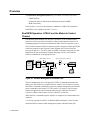
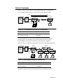
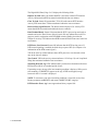
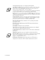
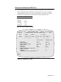
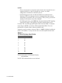
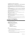
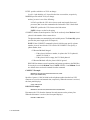
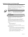
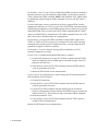
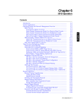
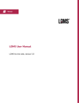
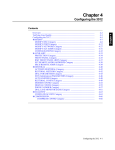
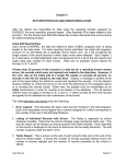
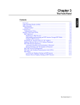
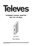
Chapter 9
DualVIEW
Overview .......................................................................................................
DualVIEW Operation: LPDA-2 and the Motorola Control Channel .......
Network Topologies .................................................................................
Preparing to Use the DualVIEW Management Feature ............................
DSU/CSU Management from NetView ...................................................
Diagnostic Commands .............................................................................
Restoral Commands .................................................................................
Netview Monitoring and Testing ..................................................................
Modem and Line Status (MLS).................................................................
Unsolicited MLS Command......................................................................
Solicited MLS Command..........................................................................
Digital MLS Panel (Page 1 of 3) ...............................................................
Digital MLS Panel (Page 2 of 3) ..............................................................
Digital MLS Panel (Page 3 of 3) ..............................................................
Transmit and Receive (TRT) Test .............................................................
Using Modem Control (MDMCNTL).......................................................
MDMCNTL Syntax and Description ...................................................
Modifying the Network Control Program (NCP)..........................................
System Configuration ...................................................................................
9-2
9-2
9-3
9-4
9-4
9-5
9-5
9-6
9-6
9-6
9-6
9-7
9-9
9-11
9-13
9-15
9-15
9-17
9-17
DualVIEW 9-1
Chapter 9
Contents
Overview
The DualVIEW management feature lets you control 3512 DSU/CSUs from:
• IBM's NetView
• A Motorola 9800 or 9300 Network Management System (NMS)
• Both concurrently
From NetView, you can test and monitor a standard set of DSU/CSU parameters.
DualVIEW is not available with 64k CC service.
DualVIEW Operation: LPDA-2 and the Motorola Control
Channel
Link Problem Determination Aid, Revision 2 (LPDA-2) is the communications
protocol used between host-based NetView software and transmission devices for
exchanging diagnostic and control information. When a NetView operator issues a
device-related command, NetView constructs a packet and routes it (through VTAM
at the host computer) to the Network Control Program (NCP) at the front-end
processor (Figure 9-1). The NCP creates an LPDA-2 command, suspends user data
transmission on the main channel (without disrupting sessions), and sends the
LPDA-2 command out on the appropriate line.
IBM LPDA-2 Protocol
NetView
Host
(VTAM)
FEP
(NCP)
Motorola Management Protocol
Local
3512
Motorola
Management
Protocol
Remote
3512
Control
Channel
DTE
Motorola NMS
Figure 9-1. Network Management Command Flow
The local transmission device recognizes the LPDA-2 command and matches the
address in it with the device's assigned NetView address. The local device converts
the LPDA-2 command to Motorola's proprietary network management protocol and
sends a command to the remote 3512. The remote 3512 answers with a response
formatted in Motorola's network management protocol, which the local device
converts to LPDA-2 and forwards, by way of the NCP, to NetView.
When NetView's command/response sequence is completed, user data transmission
continues.
A 3512 only responds to NetView or Motorola NMS commands; it does not send
unsolicited data. In contrast, both management systems send unsolicited polls.
9-2 DualVIEW
Network Topologies
Figure 9-2 shows a typical point-to-point configuration with two transmission
devices managed independently by a NetView host and a Motorola NMS.
Commands
Responses
Primary
NetView
Host
(VTAM)
FEP
(NCP)
Secondary
Local
3512
Remote
3512
Motorola
Management
Protocol
Control
Channel
DTE
Motorola NMS
Figure 9-2. Dual-Managed Point-to-Point Configuration
The Point-to-Point Device that is...
NetView Identifies as...
Closer to host
More remote from host
Primary
Secondary
The primary device receives NetView commands directly from the front-end
processor (FEP). The secondary device receives them from the local device.
Use NV Ports to select port(s) on which to receive NetView commands.
Figure 9-3 shows a multipoint configuration with NetView and NMS management.
Tributaries
Control
NetView
Host
(VTAM)
FEP
(NCP)
3512
Motorola
Management
Protocol
Control
Channel
3512
3512
3512
DTE
DTE
DTE
Motorola NMS
Figure 9-3. Dual-Managed Multipoint Configuration
The Multipoint Device(s) that is...
NetView Identifies as...
Closest to host
Remote from host
Control
Tributaries
The flow of control is the same as for the point-to-point configuration above.
DualVIEW 9-3
Dual Management mode allows for concurrent management from NetView and an
NMS. The devices respond to commands issued from either manager on a first-come
first-served basis. However, the NMS is the dominant system:
With...
NMS
The Operator Can...
Configure and monitor the device
Monitor line status
NetView
Initiate tests
Monitor the device
Monitor line status
Initiate tests
In a DDS-II SC network:
• LPDA is not supported on 3512s are managed by a Motorola NMS with DTE
Con=Muxed
• LPDA is supported on 3512s without NMS management (regardless of the
DTE Con option)
Preparing to Use the DualVIEW Management Feature
Initially, the DualVIEW feature must be configured from the 3512 front panel.
Chapter 4 describes DualVIEW front panel parameters.
It may also be necessary to modify the NCP at the IBM host site to support the
LPDA-2 management protocol and tail circuits for second-tier lines.
See “Modifying the Network Control Program” at the end of this chapter.
SDC only
NOTE: DualView is not available on the 3512 SDC Port 3 when P3=Compress.
DSU/CSU Management from NetView
NetView supports the Modem Control (MDMCNTL) command, to initiate and
terminate restoral; and the Modem and Line Status (MLS) and Transmit and Receive
Test (TRT) diagnostic commands, for DSU/CSU and line management. MLS and
TRT are part of the Network Problem Determination Application (NPDA) Test
command. NPDA is also known as Hardware Monitor. NPDA collects and stores
data from physical resources in the network and issues alerts about problems.
9-4 DualVIEW
Diagnostic Commands
From NPDA, the NetView operator can monitor transmission devices, DSU/CSUs,
and line conditions in the network.
NPDA commands are channel-specific: in a multiplexed environment, each channel
responds to NPDA commands independently. Speed and EIA readings are reported
on the port under test.
The MLS command lets you diagnose hardware errors and monitor remote EIA
status. When MLS is initiated by the NetView operator, it is solicited; when initiated
by the FEP, it is unsolicited. MLS is similar to the Motorola NMS EIA Status Report.
If the device is configured for channel sharing, EIA status can be reported for each
port based on its address. The remote address sent by NetView must match the
highest six bits of the remote device's station address. The address’s lowest bits
indicate the shared port, as follows:
Address’s Lowest Bits
Port
00
01
10
11
1
2
3
4
The TRT command initiates a block error test that helps diagnose transmission
problems. TRT is similar to the NMS or 3512 BER test. NOTE: The TRT command
interrupts TDM channels in a multiplexed environment.
Restoral Commands
From NetView’s Network Communications Control Facility (NCCF), you can issue
modem control commands. The commands can enter the 3512 through any port that
carries NetView traffic. The MDMCNTL command manages restoral operation.
You can initiate, terminate, and configure restoral phone numbers with this
command.
DualVIEW 9-5
Netview Monitoring and Testing
From NPDA, you can perform the following tests to obtain information about the
transmission device and the line status:
• Modem and Line Status (MLS)—retrieves three panels of data, including line
status parameters like RLSD losses and remote EIA interface parameters, and
basic DSU/CSU configuration data
• Transmit and Receive (TRT)—examines line quality and data error parameters
This section explains the DSU/CSU and link tests available through NPDA.
For information on accessing the NetView NPDA panels, refer to the IBM
documents NetView Operation Primer and NetView Operation Scenarios.
NOTE: The NetView panels shown in this chapter are from NetView 1.3. The panels
that appear on your NetView terminal may vary slightly from those shown.
Modem and Line Status (MLS)
The MLS command reports device status and line data such as receive level, line
quality, hardware errors, remote EIA signals, and an overview of configuration data.
This test can be either solicited (user-invoked) or unsolicited (system-invoked).
Unsolicited MLS Command
The FEP automatically invokes MLS when a predetermined throughput or
retransmission threshold (SRT) is reached, or when a shutdown or failure occurs.
The results of an unsolicited MLS are stored for analysis.
Solicited MLS Command
You can initiate MLS from NPDA. Enter Selection 1 from the LPDA-2 Command
menu and press ENTER, or invoke the MLS test command.
NOTES:
• An MLS is interruptive (it suspends requests issued to the 3512 until the test is
completed). However, it does not disrupt user sessions.
• For DDS-I applications, when DTE Con=Normal, the MLS and TRT signaling
causes DCD to toggle. This toggling is reported in the MLS status screen.
The front panels of the local and remote 3512s display:
MLS CMD RCVD
indicating that the NetView command was received and accepted. (Refer to
Chapter 3 for front panel display details.)
The MLS function consists of three panels, or pages:
• Page 1 - Basic line and data failure conditions
• Page 2 - Remote EIAs
• Page 3 - Configuration overview
9-6 DualVIEW
Digital MLS Panel (Page 1 of 3)
Figure 9-4 shows a sample of the digital MLS function, Page 1 of 3.
N E T V I E W
SESSION DOMAIN: CNM01
TBD1340
01/10/94 09:41:30
NPDA-22C
* DSU/CSU AND LINE STATUS *
PAGE 1 OF 3
* DSU/CSU and LINE PARAMETERS-LINK SEGMENT LEVEL 1 *
CNM01
CDX024
LINE064
40
PU164
+--------+ +-+
+-+ +-+
+-+ +--------+
DOMAIN
| COMC | |D|--LINE--|D| |X|--LINE--|X|-| CTRL |
+--------+ +-+
+-+ +-+
+-+ +-------DESCRIPTION,PROBABLE CAUSE: NO CRITICAL ERROR: NO PRBABLE CAUSE IDENTIFIED
RLSD LOST, AGE:
LINE QUALITY, WORST:
BIPOLAR CODE ERRORS, AGE:
REINITIALIZATION, AGE:
FAILURE ALARM, AGE:
POWER-OFF ALARM, AGE:
DSU/CSU FAILURE:
OUT OF SERVICE CODE, AGE:
OUT OF FRAME CODE, AGE:
DDS-INITIATED LOOPBACK, AGE:
SEE NEXT PAGE FOR REMOTE DTE
???
CMD==>
LOCAL DSU/CSU
REMOTE DSU/CSU
NO
NO
GOOD/0,GOOD/0
GOOD/0,GOOD/0
0
0
NO
NO
NO
NO
NO
NO
NO
NO
NO
NO
NO
NO
NO
NO
INTERFACE SUMMARY
EXPECTED
NO
GOOD/0,0-4
0-15/15 MIN
NO
NO
NO
NO
NO
NO
NO
Figure 9-4. Page 1 of 3 of the MLS Function
The Domain diagram shows Link Segment 1 and, if applicable to the line
configuration, Link Segment 2. The diagram includes the Domain, Communications
Controller, and Line names, and the Cluster Controller station and PU addresses.
The 3512s under test are displayed as highlighted boxes labeled D.
The Description, Probable Cause field shows the type of error and the probable
failing component, if a line error occurs.
Parameter values that differ from the values in the Expected column are highlighted.
DualVIEW 9-7
The Digital MLS Panel, Page 1 of 3 displays the following fields:
RLSD Lost, Age reports the time since the last link down condition was detected.
Age is the elapsed time since the last RLSD loss; it is reported in 8-second
increments from 0 to 112.
Line Quality, Worst reports the current line quality in the form of a rating and
index, followed by the worst rating and index detected over the last two minutes.
Bipolar Code Errors, Age reports the number of bipolar code errors detected in a
15-minute window. A bipolar code error is defined as an invalid bipolar code
violation, which may be caused by impulse noise or a configuration mismatch.
(Valid bipolar code violations are used in the DDS protocol to pass control and status
information and are not included in this field.)
Age is the elapsed time since the last bipolar code error, reported in 8-second
increments from 0 to 112. From two minutes until the end of the 15-minute window,
the age is reported as 2 min+. When 15 minutes have passed with no bipolar code
errors, Age is reported as 0.
Reinitialization, Age indicates whether DSU initialization (power cycle or reboot)
occurred within the last two minutes. Age is reported in 8-second increments to a
maximum of 112.
Failure Alarm, Age is not supported and always reports NO.
Power-Off Alarm, Age is not supported and always reports NO.
DSU/CSU Failure is not supported and always reports NO.
Out of Service Code, Age indicates whether an out-of-service code has been
received in the two minutes preceding the digital MLS command. NetView reports
N/A for 3512s operating as limited distance modems (LDMs).
Out of Frame Code, Age indicates whether an out-of-frame code has been received
in the two minutes preceding the digital MLS command. NetView reports N/A for
3512s operating as LDMs.
DDS-Initiated Loopback, Age indicates whether the 3512 has been placed in a
DSU/CSU loopback in the two minutes preceding the digital MLS command. While
the loopback is in progress, Age is reported as eight seconds. NetView reports N/A
for 3512s operating as LDMs.
9-8 DualVIEW
Digital MLS Panel (Page 2 of 3)
To view the Digital MLS Panel, Page 2 of 3 (Figure 9-5), press ENTER. This panel
reports the status of the remote 3512's EIA signals.
N E T V I E W
SESSION DOMAIN: CNM01
TBD1340
01/10/94 09:41:30
NPDA-22C
* DSU/CSU AND LINE STATUS *
PAGE 2 OF 3
* REMOTE DSU/CSU INTERFACE-REMOTE DEVICE STATUS-LINK SEGMENT LEVEL 1 *
CNM01
CDX024
LINE064
40
PU164
+--------+ +-+
+-+ +-+
+-+ +--------+
DOMAIN
| COMC | |D|--LINE--|D| |X|--LINE--|X|-| CTRL |
+--------+ +-+
+-+ +-+
+-+ +--------+
STATUS AT COMMAND
EXECUTION TIME
REQUEST TO SEND:
OFF
CLEAR TO SEND:
OFF
RECEIVED LINE SIGNAL DETECTOR:
N/A
DATA TERMINAL READY:
ON
DTE POWER LOSS DETECTED:
OFF
TEST CONTROL:
N/A
ACTIVITY DURING TWO
MINUTES BEFORE COMMAND
NO
NO
YES
NO
NO
NO
REMOTE DEVICE
STREAMING DETECTED, AGE: NO
DTE INTERFACE ERROR, AGE: NO
SEE NEXT PAGE FOR LINK AND DSU/CSU CONFIGURATIONS
???
CMD==>
Figure 9-5. Page 2 of 3 of the MLS Function
The Status at Command Execution Time column (“Status”) indicates the status
(ON or OFF) of the DTE interface signals at the remote 3512 when the MLS
command was executed.
The Activity During Two Minutes Before Command column (“Activity”) indicates
whether the status of the DTE interface signals at the remote 3512 changed (YES or
NO) within the two minutes preceding the execution of the MLS command.
DualVIEW 9-9
The Digital MLS Panel, Page 2 of 3 displays the following fields:
Request To Send: Status ON means that RTS is ON at the remote DTE interface.
Activity ON means that RTS has transitioned within the last two minutes.
Clear To Send: Status ON means that CTS is ON at the remote DTE interface.
Activity YES means that CTS has transitioned within the last two minutes.
Received Line Signal Detector: The Status column displays N/A. Activity YES
means that DCD has transitioned within the last two minutes.
Data Terminal Ready: Status ON means that the DTE is powered up and ready to
transmit and receive data. From a dial tail circuit, ON may indicate that a call is in
progress (used in conjunction with DTR-DSR control signaling, described in
Chapter 4). Activity YES indicates that DTR has transitioned at least once in the last
two minutes.
DTE Power Loss Detected: Status ON indicates that the DTE has lost power. If
DTR control signaling is enabled, the field always reports OFF. (See Chapter 4 for
information on the DTR control signal.)
YES in the Activity column indicates that a DTE power loss was detected at least
once in the last two minutes.
Test Control: YES in the activity column indicates a V.54 Loop 3 (Local Loop Back
Wrap) has terminated within the last two minutes.
Streaming Detected, Age: YES indicates that a port has been disconnected because
RTS has been ON for an extended period of time.
If streaming occurs, the age of the last streaming condition is displayed. If the port is
still streaming, CURRENTLY appears as the age; if RTS has dropped, an age
between 8 and 112 seconds is displayed.
NOTE: To reconnect a port after a streaming condition is corrected, use the Port
Restore parameter ( MODIFY main menu, MODIFY PORT category).
*
DTE Interface Error, Age is not supported and always reports NO.
9-10 DualVIEW
Digital MLS Panel (Page 3 of 3)
To view Page 3 of the digital MLS parameters, press ENTER. This panel provides a
summary of 3512 configuration data. Figure 9-6 is a sample of this panel.
N E T V I E W
SESSION DOMAIN: CNM01
TBD1340
01/10/94 09:41:30
NPDA-22C
* DSU/CSU AND LINE STATUS *
PAGE 2 OF 3
* CONFIGURATION SUMMARY-LINK SEGMENT LEVEL 1 *
CNM01
CDX024
LINE064
40
PU164
+--------+ +-+
+-+ +-+
+-+ +--------+
DOMAIN
| COMC | |D|--LINE--|D| |X|--LINE--|X|-| CTRL |
+--------+ +-+
+-+ +-+
+-+ +--------+
LINK CONFIGURATION: POINT-TO-POINT
LOCAL DSU/CSU
TYPE-MODEL, TEST MODE:
3512-02 SOLICITED
SPEED:
56.0 KBPS
NETWORK FUNCTION:
PRIMARY
DSU/CSU IN IDLE STATE:
NO
LPDA MICROCODE, CARD LEVEL: 5, 0
SERIAL NUMBER:
0000124
TYPE OF LINE:
DDS
COMMAND RETRIED:
NO
MANUAL TEST, AGE:
NO
DSU/CSU ADDRESS:
01
DTE INTERFACE CONNECTION: DTE
REMOTE DSU/CSU
3512-08 SOLICITED
56.0 KBPS
SECONDARY
NO
5, 0
0000116
DDS
N/A
NO
40
DCE
???
CMD==>
Figure 9-6. Page 3 of 3 of the MLS Function
DualVIEW 9-11
The Digital MLS Panel, Page 3 of 3, displays the following fields:
Type-Model, Test Mode depends upon the NetView software version. It may have
been necessary to enter a model number other than 3512 at the front panel. For
details, refer to the “ DUALVIEW” section in Chapter 4.
*
Test Mode identifies whether the most recent digital MLS command was initiated by
an operator (SOLICITED) or by the controlling node (UNSOLICITED).
Speed reports line or port speed depending on the DTE Config option. With Normal
or BitSteal, the reported speed corresponds to the line rate. With Muxed, the reported
speed corresponds to the port rate.
Network Function identifies the 3512's place in the network topology. On a pointto-point link, the possible functions are PRIMARY and SECONDARY; on a multipoint link, the possible functions are CONTROL and TRIBUTARY.
DSU/CSU in Idle State indicates whether the 3512 is operating with a default
station address of FF16.
LPDA Microcode, Card Level reports DualVIEW major and minor firmware
levels, respectively.
Serial Number identifies the 3512's serial number.
Type of Line reports LDM or DDS. This parameter displays the user-configured
values from the 3512 DUALVIEW main menu tree.
*
Command Retried indicates whether the local 3512 has retried a command to the
remote device.
Manual Test, Age indicates any test or loopback not initiated from NetView.
DSU/CSU Address identifies the station address as configured for both the local and
remote 3512s. For information on selecting an appropriate address, refer to
Chapter 4, “Config DualVIEW” section.
DTE Interface Connection indicates whether the device's DTE interface is
configured to be connected to a DTE or another transmission device (DCE).
9-12 DualVIEW
Transmit and Receive (TRT) Test
3512s report block errors in response to the TRT command. This test checks line
quality and transmission performance by causing a pair of 3512s to exchange a
predetermined bit sequence. The test is performed by a solicited (user-invoked)
command. The number of bits per block varies with the digital line rate:
Line Rate
Bits per Block
2400 bps
4800 bps
9600 bps
19200 bps
56000 bps
256
512
1024
2048
6144
Figure 9-7 shows a sample TRT panel.
N E T V I E W
SESSION DOMAIN: CNM01
TBD1340
01/10/94 09:45
NPDA-25B
* TRANSMIT RECEIVE TEST-LINK SEGMENT LEVEL 1 *
PAGE
CNM01
DOMAIN
CDX024
LINE064
40 PU164
+--------+ +-+
+-+ +-+
+-+ +--------+
| COMC | |D|--LINE-- |D| |X|--LINE-- |X|-| CTRL |
+--------+ +-+
+-+ +-+
+-+ +--------+
TYPE-MODEL:
DSU/CSU ADDRESS:
CURRENT TRANSMIT SPEED:
SPEED IN USE:
RLSD LOST:
LINE QUALITY:
BIPOLAR CODE ERRORS DURING TEST:
NUMBER OF BLOCKS:
RECEIVED:
RECEIVED WITH ONE OR MORE ERRORS:
LOCAL DSU/CSU
REMOTE DSU/CSU
3512-01
01
56.0 KBPS
N/A
NO
GOOD/0
0
3512-04
40
56.0 KBPS
N/A
NO
GOOD/0
0
16
0
16
0
???
CMD==>
Figure 9-7. Sample TRT Panel
DualVIEW 9-13
NOTES:
• This test is interruptive (it suspends requests issued to the 3512 until the test is
completed). However, it does not disrupt user sessions. In a TDM
configuration, all channels are affected by the test.
• In Dual Management mode, the Motorola NMS must reestablish control
following a TRT. If you attempt to execute a command from either network
management system shortly after you requesting a TRT, you may get a timeout
message. In this situation, reissue the command.
• For DDS-I applications, when DTE Con=Normal, the MLS and TRT signaling
causes DCD to toggle. This toggling is reported in the MLS status screen.
To initiate TRT, select the appropriate option number from the LPDA-2 Command
menu and press ENTER, or invoke the TRT command from NPDA. The test is
performed for 16 blocks of data, which is the default value.
Alternately, specify an option, a shown in Table 9-1. NOTE: In BitSteal and Muxed
modes, a low number (1-3) may cause the test to exceed acceptable timeout limits.
Table 9-1.
TRT Block Exchange Specification
Enter...
1
2
3
4
5
6
7
8
9
10
To Exchange...
16
32
48
64
80
96
112
128
144
160
The local and remote 3512 front panels display:
TRT CMD RCVD
The TST LED indicates that the test was initiated.
9-14 DualVIEW
The digital TRT screen displays the following fields:
Type-Model describes the device attached to NetView— either 3512-Pn (where Pn
indicates the port number, 1-4) or an IBM equivalent (e.g., 5822-10), based upon the
user-selected type number in the 3512 DUALVIEW main menu tree.
*
DSU/CSU Address identifies the station address of both the local and remote device.
This address is the one that the user has entered in the device's DUALVIEW main
menu tree.
*
Current Transmit Speed reports line or port speed, depending on the DTE Config
option. When DTE Config=Normal or BitSteal, the reported speed corresponds to
the DSU line rate. When DTE Config=Muxed, the reported speed corresponds to the
port’s assigned channel rate.
Speed in Use: NetView displays N/A for this field.
RLSD Lost indicates whether link down has occurred during the test. If so, YES
displays; otherwise, NO displays.
Line Quality reports the current line quality.
Bipolar Code Errors During Test reports the number of invalid bipolar code
violations detected during the test.
Number of Blocks Received indicates the total number of blocks received during
the TRT test.
Number of Blocks Received with One or More Errors indicates the total number
of block errors received during the TRT test.
Using Modem Control (MDMCNTL)
From NetView, the MDMCNTL command in NCCF is used to initiate and terminate
switched analog restoral operations.
MDMCNTL Syntax and Description
The MDMCNTL command syntax for 3512s is:
MDMCNTL ID=major_node
,STATION=device_name
[,LEVEL=level#]
[,MODEM=modem_location]
[,CONNECT=(phone#,DISCONN]
where:
MDMCNTL ID specifies the major node.
major_node is the PU name (8 characters maximum) of the front-end processor
responsible for passing the command to the local 3512.
STATION specifies the controller.
device_name is the PU name (8 characters maximum) of the controller at the end
of the link with which the remote 3512 is associated.
DualVIEW 9-15
LEVEL specifies which tier of 3512s to change.
level# is 1 (the default) or 2. It specifies the first or second tier, respectively.
MODEM specifies which 3512(s) to change.
modem_location is one of the following:
LOCAL specifies the 3512 device closest to the major node (front-end
processor) that issues the command to the link station. This is the default.
REMOTE specifies the 3512 closest to the link station.
NOTE: Always use the Local setting.
CONNECT initiates restoral operation. This can be used only when Modem=Local.
phone# is the number of the remote device.
The phone number can contain digits and variable pauses. The Pause Dly option
specifies the pause length (refer to Chapter 4).
NOTE: If the CONNECT command’s phone# field does not specify a phone
number, phone#1 stored in the 3512 is dialed. If CONNECT does specify a
phone number, then:
• If Restoral Method=Integral
— If the phone# field has a number, it replaces the 3512’s phone#1,
and the 3512 dials it
— If the phone# field is empty, the 3512 dials phone#1
• If Restoral Method=A/B, the phone# field is ignored
DISCONN terminates restoral operations and returns operation to the DDS line.
It can only be used with Modem=Local. NOTE: LEVEL=1 and Modem=Local
are default values and can be omitted from the command.
CONNECT Example:
MDMCNTL ID=PEP342A,STATION=P230731D, CONNECT=(9P15082614000)
Specifies 9 (pause) 1-508-261-4000 as the telephone number that the local 3512
connects to, to receive and transmit data, respectively. When the connect is received,
the front panel displays:
CNCT CMD RCVD
DISCONN Example:
MDMCNTL ID=PEP342A,STATION=P230731D,DISCONN
Disconnects the 3512 from the alternate line and connects on the primary line.
When the disconnect is received, the front panel displays:
DISCNCT CMD RCVD
9-16 DualVIEW
Modifying the Network Control Program (NCP)
This section should be used by the NetView systems analyst, programmer, or
engineer, or IBM field support personnel responsible for generating the NCP.
The NCP controls the flow of information between the FEP and the attached devices.
The FEP must be instructed to send and receive LPDA messages on a per-port basis
and must be provided with information about the line configuration.
IMPORTANT: The DualVIEW Management feature requires NCP revision 4.2
(V4R2) or later to support the LPDA-2 protocol.
For information on:
Refer to:
Defining an NCP
configuration
Network Control Program (NCP), System Support Programs
(SSP), and Emulation Program (EP) Resource Definition
Guide; NCP, SSP, and EP Resource Definition Reference
Generating and loading
the Load Module
NCP, SSP, and EP Generation and Loading Guide
System Configuration
LPDA support for 3512s with the DualVIEW feature is accomplished by
(re-)generating the NCP. Making changes to the NCP generation is the most
permanent means of defining your network configuration and LPDA
communication.
From NCCF, you can make some temporary changes to the LPDA definition
statement with the LPDA command. This command can enable LPDA
communication without changing the NCP generation. It can also temporarily
override LPDA support already defined in the NCP generation until the 3512s have
been installed and enabled in your network. Changes made with LPDA remain in
effect until:
• Another LPDA command is issued
• An inactivity condition occurs
• A procedure such as NCP reload or power cycle is initiated
One of the following scenarios should describe your network before installation of
DualVIEW-equipped 3512s:
• 1: A NetView-managed network with DSU/CSU, not using the LPDA protocol,
to be upgraded to include 3512s with the DualVIEW feature and LPDA-2
• 2: A NetView-managed network with LPDA DSU/CSU that is to be upgraded
to include 3512s with the DualVIEW feature and LPDA-2
• 3: A NetView-managed network with LPDA-2 DSU/CSU that is to be
upgraded to include 3512s with the DualVIEW feature
DualVIEW 9-17
For Scenarios 1 and 2, if your 3512s are installed but LPDA has not been enabled in
the NCP generation, you can temporarily enable LPDA-2 on the first tier using the
TYPE3 option in the LPDA command. NOTE: With TAILING=YES, LPDA cannot
be dynamically changed using the LPDA command. The sense code 0877 000C is
displayed.
If, on the other hand, you have regenerated your lines to support LPDA-2 before
installing and enabling your 3512s, you can use the NCCF LPDA command with the
NONE option to temporarily override LPDA support until you install your 3512s and
enable DualVIEW. Then you can use the NCCF LPDA command with the TYPE3
option to reenable LPDA-2 communication. The LPDA command allows you to disable a whole line or individual drops on a multipoint line.
For Scenario 2, you can use the LPDA command to change LPDA support from
TYPE1 or TYPE2 to TYPE3 as long as the existing line is either point-to-point or
multipoint and not multi-tiered. For a multi-tiered line, you must change the NCP
generation to upgrade to LPDA-2 capability.
For Scenario 3, if you are using the existing NetView capabilities, no NCP
generation changes are necessary.
If your 3512s are installed and the DualVIEW feature is enabled:
1) Perform NCP generation or use the NCCF LPDA command with the TYPE3
option to temporarily provide LPDA support, and make changes to the NCP
generation at a later time.
2) From NetView, use the NCCF LPDA command with the QUERY option to
verify the generation for the line.
3) Initiate the TRT function to test communication.
If your 3512s are not installed and you want to change the NCP generation prior to
their installation, do the following:
1) Perform NCP generation.
2) From NetView, use the NCCF LPDA command with the QUERY option to
verify the generation for the line.
3) Use the NCCF LPDA command with the NONE option to discontinue
LPDA-2 communication attempts until the DualVIEW feature is installed and
enabled in the 3512s. This avoids error logs on unsolicited MLS commands.
4) Install and enable the 3512s.
5) From NetView, use the NCCF LPDA command with the TYPE3 option to
reenable LPDA-2 communication.
Initiate the TRT function to test communication.
9-18 DualVIEW