1
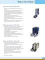
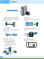
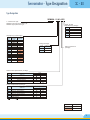
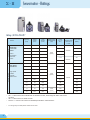
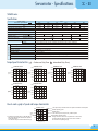
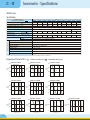
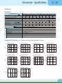
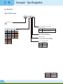
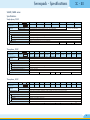
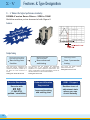
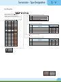
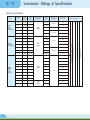
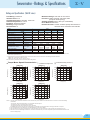
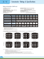
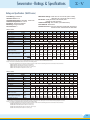
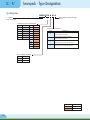
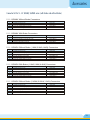
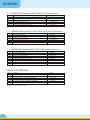
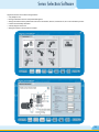
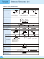
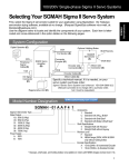
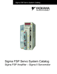
AC SERVO SYSTEM
Introduction
About Us
Larsen & Toubro (L&T) is a technology-driven USD 9.8 billion company that
infuses engineering with imagination. The Company offers a wide range of
advanced solutions, in the fields of Engineering, Construction, Electrical &
Automation, Machinery and Information Technology.
L&T Switchgear, which forms part of the Electrical & Automation business, is
India's largest manufacturer of low voltage switchgear, with the scale,
sophistication and range to meet global benchmarks. With over four decades
of experience in this field, the Company today enjoys a leadership position in
the Indian market with growing presence in international markets.
It offers a complete range of products including; controlgear, powergear,
motor starters, energy meters, wires and host of other accessories. Most of
our products conform to international standards, carry CE markings and are
certified.
Switchgear Factory,
Mumbai
Servo Power
Larsen & Toubro’s New Generation Servomotor and Drive incorporates
the latest technological advancements in motion control system.
Servomotor and Servopack are
used in closed loop control systems
in which work is the control variable.
The digital Servomotor controller
directs operation of the Servomotor
by sending velocity command
signals to the Servopack, which
drives the Servomotor. An integral
feedback device provide the
Servomotor's position and velocity
feedback that the controller
compares to its programmed
motion profile and uses to alter its
velocity signal.
AC Servomotors are used in AC
Servo mechanisms which require
rapid and accurate response
characteristics. To obtain these
characteristics, Servomotors have
small-diameter high-resistance
rotors. The small diameter provides
low inertia for fast starts, stops, and
reversals, while the high resistance
provides a nearly linear speedtorque relationship for accurate
control.
In an ideal Servomotor, torque at
any speed is directly proportional to
control-winding voltage. In practice,
however, this relationship exists
only at zero speed because of the
inherent inability of an induction
motor to respond to voltage input
changes under conditions of light
load.
L&T introduces Servo system with
enhanced performance and
functions. S
- II series, S
- V series,
Junma series and MP series
controllers are easy to use and
conforms to world standard.
Manufactured by :
YASKAWA Electric Corporation
JAPAN
Range of Servo Products
Sigma-II Series Servo Drives - 30W to 90 kW
•
•
•
•
•
•
•
Choice of Low inertia, Middle inertia and High inertia
motors
Very good peak torque performance (approx 300%) for
longer period of time to help in quick acceleration
17 bit incremental encoder* (resolution-131072 PPR) as
standard with Serial Interface to Servopack. Option for
absolute encoder
Choice of Servo Drives with 200V & 400V
Speed Control, Position Control, Torque Control and
Contact Speed as Standard
On the fly mode change through digital input possible as
standard
Analog / Pulse train reference as standard with network
option of Mechatrolink-II, Profibus, Devicenet
JUNMA Series Servo Drives - 100W to 750W
•
•
•
•
•
•
•
•
Excellent cost to performance ratio for Position Control
Industry’s first plug and play type Servo Drive
Achieve optimum Servo performance without gain setting
and tuning parameters (No gain tuning and parameter
setting required)
Great stability despite of load changes
Encoder resolution : 10000 PPR
Option for servomotor with electromagnetic brake
Selectable electronic gear 1000 PPR, 2500 PPR, 5000
PPR and 10000 PPR
Option of Mechatrolink- II communication
Sigma-V Series Servo Drives - 50W to 15 kW
•
•
•
•
•
•
•
Very High Performance Servo with outstanding frequency
response of 1600 Hz (best in Industry)
Choice of Low inertia, Middle inertia and High inertia
motors
Very good peak torque performance (approx 350%) for
longer period of time to help in quick acceleration
20 bit incremental encoder (resolution-1,048,576 PPR) as
standard with Serial Interface to the Servopack
Max speed upto 6000 rpm
Option for Servomotor with electromagnetic brake
Faster setup, simple tuning process with tuneless
function
* Except SGMAH & SGMPH series
1
Features
S
- II
Servo Drives - 30 W to 90 kW
Easy setup and operation/Online auto-tuning
All-in-one control
Simple set-up : Just plug-and-play enhanced inertia
matching precision eliminates the need for Servo
gain adjustment.
Position, torque and speed can be controlled
independently, with simple switching between
control modes.
Online
auto-tuning
Position
control
Speed
control
Torque
control
Load inertia
Servopack
Current (torque) limit
Selection of internal speed presets
The peak current input to the motor can be limited to
minimize occurrence of overtorque and reduce
machinery damage.
The motor can be operated at any of the three preset
user speeds.
Overtorque
Torque Limit
Overcurrent
Load
Current limit
Motor
Load
SPEED1
SPEED2
Motor
SPEED3
Contact input
Servopack
High resolution serial encoder
Feed forward compensation
?
Error checking eliminates positioning
Feed forward compensation provides reduced
positioning time.
inaccuracies due to electrical noise
?
Reduces number of wires to half
Command
?
Absolute encoder: 15 to 7 wires
?
Incremental encoder: 9 to 5 wires
Motor
Speed
?
Amplifier automatically recognizes the motor
and optimizes parameters
Time (t)
Shorter positioning time
SGMAH
y
displa
Alarm
Does
not
match
SGMSH
2
Servomotor - Type Designation
S
- II
Type Designation
SGMAH - 01 A 1 A 2 S
S
- II Servomotor Type
SGMAH: Super High Power Rate Type
SGMGH: High-Speed Feed Type
Brake, Oil Seal
Specifications (7th Digit)
1
Capacity kW (1st & 2nd Digit)
Code
SGMAH
A3
A5
01
02
04
05
06
09
13
20
30
44
55
75
1A
1E
0.03
0.05
0.1
0.2
0.4
No Brake, No Oil Seal
S
No Brake, Oil Seal
B
C
D
90V Break, No Oil Seal
24V Break, No Oil Seal
Oil Seal +90VDC Brake
E
Oil Seal +24VDC Brake
SGMGH
Voltage (3rd Digit)
0.45
Code
Voltage(V)
A
200
D
400
0.85
1.3
1.8
2.9
4.4
5.5
7.5
11
15
Design Procedure A
(5th Digit)
Serial Encoder Specifications (4th Digit)
Type
Shaft End
Code
1
2
A
B
C
SGMAH
SGMGH
16-Bit Absolute
17-Bit Absolute
13-Bit Incremental
16-Bit Incremental
17-Bit Incremental
Shaft End Specifications (6th Digit)
Type
Code
2
3
4
5
6
8
Shaft End
SGMAH
SGMGH
Straight, no key
Taper 1/10, with parallel key
Straight, key
Taper 1/10, with woodruff key
Straight, key, tapped
Straight, tapped
Standard
Optional
Color Code
Voltage (V)
200
200/400
3
Servomotor - Ratings
S
- II
Ratings (30 W to 90 kW)*
Series
Capacity
(kW)
Rated
Torque
(N.m)
Peak
Torque
(N.m)
SGMAH
0.03
0.0955
0.286
0.0166
0.05
0.159
0.477
0.022
Rated Speed
(Peak Speed)
(rpm)
Inertia
(kg. m2
-4
10 )
Maximum
Allowed Load Rated Power
(kW/s)
Moment of
Inertia
5.49
Small-Capacity
Super High
Power Rate
Series.
Faster
acceleration
with lower
0.1
0.318
0.955
0.2
0.637
1.91
0.4
1.27
3.82
3000
(5000)
0.0364
27.8
0.106
38.2
0.173
inertia
SGMGH
11.5
30 times
93.7
20 times
0.75
2.39
7.16
0.672
84.8
0.45
2.84
8.92
7.24
11.2
0.85
5.39
13.8
13.9
20.9
1.3
8.34
23.3
20.5
33.8
1.8
11.5
28.7
31.7
41.5
2.9
18.6
45.1
46
4.4
28.4
71.1
67.5
120
5.5
35
87.6
89
137
7.5
48
119
125
184
11
70
175
281
174
15
95.4
224
315
289
High Speed
Feed Series.
Medium-Capacity
High speed
rotation
required
without load
1500
(3000)
1500
(2000)
5 times
?
All S
Servomotors are available with an absolute encoder, electromagnetic brake and oil seal
-P
as option
?
All S
-P
Servomotor use serial encoder
?
Refer to S
-P
Servo user manual for detailed specifications and dimensions
*
4
For ratings beyond 15kW please contact branch office
75.3
Servomotor - Specifications
S
- II
SGMAH series
Specifications
Applied Voltage
Servomotor Type SGMAH Rated Output
W
Rated Torque
N•m
230V
Instantaneous Peak Torque
N•m
Rated Rotation Speed
min –1
Max. Rotation Speed
min –1
Moment of Inertia (JM)
kg • m2 x 10
Allowable Load
Moment of Inertia (JL)
Rated Power Rate
as much as the
Moment of Inertia
kW/s
Basic Specifications
Applicable Encoder
A3A
30
A5A
50
01A
100
02A
200
04A
400
08A
750
0.0955
0.159
0.318
0.637
1.27
2.39
1.91
3.82
7.16
0.106
0.173
0.286
0.477
0.955
3000
5000
4
0.0166
0.0364
0.0220
5.49
11.5
38.2
27.8
Incremental Encoder (13 bits: 2048P/R)
Option
Incremental Encoder (16 bits: 16384P/R), Absolute Encoder (16 bits: 16384P/R)
Continuous
Insulation Class
Class B
Ambient Temperature
0 to + 40°C
Ambient Humidity
20 to 80% (non-condensing)
Vibration Class
15µm or below
Enclosure
Totally-enclosed, self-cooled, IP55 (excluding shaft opening)
Vibration Resistance
Vibration acceleration 49m/s2
Mounting
Flange-mounted
Torque-Speed characteristics
SGMAH-A5A
SGMAH-01A
SGMAH-02A
5000
5000
5000
5000
4000
4000
4000
4000
3000
3000
3000
A
Speed
(min–1)
B
2000
1000
0
A
2000
0
0.1 0.2 0.3 0.4
Torque (N . m)
SGMAH-04A
Speed
(min–1)
B
2000
0.15 0.3 0.45 0.6
Torque (N . m)
0
0
3000
A
B
2000
1000
0.25 0.5
0.75
1
Torque (N . m)
0
0
0.5 1
1.5 2
Torque (N . m)
SGMAH-08A
5000
4000
4000
3000
A
A
1000
0
5000
Speed
(min–1)
B
2000
1000
0
Speed
(min–1)
B
1000
0
84.8
( A : Continuous Duty Zone B : Intermittent Duty Zone)
SGMAH-A3A
Speed
(min–1)
93.7
Standard
Time Rating
Speed
(min–1)
0.672
20 times
or less
30 times
or less
3000
A
B
2000
1000
0
1
2
3
0
4
0
2
6
4
Torque (N . m)
8
Torque (N . m)
How to read a graph of speed and torque characteristics
SGMAH-A3A
The output torque will decrease if the speed exceeds the rated speed.
5000
Rated operating point
4000
Speed 3000
A
(min –1)
2000
A. Continuous operating range
Safe range allowing the continuous operation
of the Servomotor
The effective torque must be within this range.
Rated torque
The same torque is output at any rotation speed.
B
1000
0
0
0.1 0.2 0.3 0.4
Torque (N . m)
B. Repetitive operating range
Range where the motor can be operated for a short time,
provided that the effective torque of the motor is within
the continuous operating range.
5
S
- II
Servomotor - Specifications
SGMGH series
Specifications
Applied Voltage
Servomotor Type SGMGH Rated Output
kW
Rated Torque
N•m
230V
A 1EAo
A
A 20Ao
A 44Ao
05Ao
A 09Ao
A 13Ao
A 30Ao
A 75Ao
A 1AAo
A 55Ao
11
15
1.3
0.45
0.85
1.8
2.9
5.5
7.5
4.4
N•m
Rated Rotation Speed
min–1
Max. Rotation Speed
min–1
Moment of Inertia (J)
kg•m2 x10
Allowable Load
Moment of Inertia
Rated Power Rate
Basic Specifications
Applicable Encoder
5.39
2.84
Instantaneous Peak Torque
13.8
8.92
8.34
11.5
23.3
18.6
28.7
35.0
28.4
45.1
48.0
70.0
95.4
221
71.1
87.6
119
175
67.5
89.0
125
281
315
137
184
174
289
1500
3000
4
2000
7.24
13.9
20.5
31.7
46.0
as much as the
Moment of Inertia
kW/s
11.2
20.9
33.8
41.5
75.3
Standard
Incremental Encoder (17 bits: 16384P/R*)
Option
Absolute Encoder (17 bits/20 bits: 16384P/R*)
5 times or less
120
Time Rating
Continuous
Insulation Class
Class F
Ambient Temperature
0 to +40°C
Ambient Humidity
20 to 80% (non-condensing)
Vibration Class
15µm or below
Enclosure
Totally-enclosed, self-cooled, IP67 (excluding shaft opening)
Vibration Resistance
Vibration acceleration 24.5m/s2 (2.5G)
Mounting
Flange-mounted
* : For 17-bit and 20-bit encoders (without divider), pulses output from Servopack are also 16384 P/R.
Torque-Speed characteristics
( A : Continuous duty zone B : Intermittent duty zone)
SGMGH-05Ao
A
3000
2000
A
2000
Speed
(min–1)
B
1000
A
2
4
6
8
0
10
0
5
Speed
(min–1)
1000
B
10
20
30
0
40
10
30
2000
Speed
(min–1)
1000
B
A
0
SGMGH-55Ao
A
20
SGMGH-44Ao
A
10
20
30
40
0
50
A
0
B
20
Torque (N . m)
40
60
80
Torque (N . m)
SGMGH-75Ao
A
3000
3000
SGMGH-1AAo
A
2000
SGMGH-1EAo
A
2000
2000
2000
A
Speed
(min–1)
B
A
Speed
(min–1) 1000
B
Speed
(min–1) 1000
B
A
A
B
1000
20
40
60
Torque (N . m)
6
0
Torque (N . m)
2000
0
0
0
20
3000
Torque (N . m)
0
15
3000
2000
Speed
(min–1)
1000
10
SGMGH-30Ao
A
SGMGH-20Ao
A
A
B
Torque (N . m)
3000
Speed
(min–1)
1000
A
1000
Torque (N . m)
0
Speed
(min–1)
B
1000
0
SGMGH-13Ao
A
3000
2000
Speed
(min–1)
0
SGMGH-09Ao
A
3000
80
100
0
0
50
100
Torque (N . m)
150
0
0
50
100
150
Torque (N . m)
200
0
0
50
100
150
Torque (N . m)
200
250
Servomotor - Specifications
S
- II
SGMGH series
Specifications
Applied Voltage
Servomotor Type SGMGH Rated Output
kW
Rated Torque
N•m
400V
05Do
A 09Do
A 13Do
A 20Do
A 30Do
A 44Do
A 55Do
A 75Do
A 1ADo
A 1EDo
A
0.45
0.85
1.3
1.8
2.9
4.4
5.5
7.5
11
15
2.84
8.34
5.39
11.5
18.6
28.4
35.0
48.0
70.0
95.4
28.7
45.1
71.1
90.7
123
175
221
Instantaneous Peak Torque
N•m
Rated Rotation Speed
min –1
Max. Rotation Speed
min –1
Moment of Inertia (J)
kg • m2 x 10
Allowable Load
Moment of Inertia
Rated Power Rate
as much as the
Moment of Inertia
kW/s
11.2
Standard
Incremental Encoder (17 bits: 16384P/R)
Option
Absolute Encoder (17 bits: 16384P/R)
Basic Specifications
Applicable Encoder
8.92
13.8
23.3
1500
3000
4
7.24
20.5
13.9
20.9
33.8
2000
31.7
46.0
67.5
89.0
125
281
315
41.5
5 times
or less
75.3
120
137
184
174
289
Time Rating
Continuous
Insulation Class
Class F
Ambient Temperature
0 to + 40°C
Ambient Humidity
20 to 80% (non-condensing)
Vibration Class
15µm or below
Enclosure
Totally-enclosed, self-cooled, IP67 (excluding shaft opening)
Vibration Resistance
Vibration acceleration 24.5m/s2
Mounting
Flange-mounted
Torque-Speed characteristics
( A : Continuous Duty Zone B : Intermittent Duty Zone)
SGMGH-05Do
A
3000
2000
A
0
2
4
6
8
0
10
A
0
5
Torque (N . m)
SGMGH-30Do
A
15
0
20
2000
SGMGH-44Do
A
0
20
30
40
0
50
A
0
20
0
60
80
Torque (N . m)
SGMGH-1ADo
A
Speed
(min–1) 1000
40
0
30
A
0
0
0
B
10
20
30
40
Torque (N . m)
SGMGH-55Do
A
Speed
(min–1)
1000
B
Torque (N . m)
2000
20
SGMGH-75Do
A
3000
2000
Speed
(min–1)
1000
B
10
10
3000
2000
A
0
Speed
(min–1)
1000
B
Torque (N . m)
3000
Speed
(min–1)
1000
0
10
2000
A
Torque (N . m)
3000
0
Speed
(min–1)
1000
B
SGMGH-20Do
A
3000
2000
Speed
(min–1)
1000
B
SGMGH-13Do
A
3000
2000
Speed
(min–1)
1000
0
SGMGH-09Do
A
3000
2000
A
Speed
(min–1)
1000
B
20
40
60
Torque (N . m)
80
100
0
0
A
B
50
100
150
Torque (N . m)
SGMGH-1EDo
A
2000
Speed
(min–1) 1000
B
A
50
100
150
Torque (N . m)
200
0
0
A
50
B
100
150
200
250
Torque (N . m)
7
Servopack - Type Designation
S
- II
Type Designation
SGDM/SGDH Servopack
SGDH - 08 A E - S
S
-II Servopack Type
SGDM
SGDH
Phase (6th Digit) (only for SGDH
type Servopack)
Capacity kW (1st & 2nd Digit)
Blank
Code
Capacity
Code
Capacity
A3
0.03
50
5
A5
0.05
60
6
1
0.1
75
7.5
2
0.2
1A
11
4
0.4
1E
15
5
0.5
10
1
15
1.5
20
2
30
3
S
Three-phase (0.5 to 55kW)
Single-phase (750W)
Design Version A (5th Digit)
(only for SGDM type Servopack)
Model (4th Digit)
E: Speed, Torque, Position (SGDH)
D: Speed, Torque, Position (SGDM)
Source Voltage (3rd Digit)
Code
Voltage(V)
A
200
D
400
Color Code
Voltage (V)
200
200/400
8
Servopack - Specifications
S
- II
SGDM/SGDH series
Specifications
Single-phase, 200V
Servopack Type
SGDH
A3AE
A5AE
01AE
02AE
04AE
08AE-S
15AE-S
Applicable
Servomotor
SGMAH
A3A
A5A
01A
02A
04A
08A
13A
Main Circuit
For single-phase, 200 to 230VAC (+10%, -15%) (50/60Hz)
Control Circuit
For single-phase, 200 to 230VAC (+10%, -15%) (50/60Hz)
220 TO 230VAC
+10 to–15% (50/60hZ)
Control Method
Single-phase full-wave rectification / IGBT / PWM / sine-wave current drive method
Feedback
Serial encoder (incremental/absolute value)
Conditions
Basic Specifications
Input Power
Supply
Usage/Storage Temperature
0 to 55°C / -20 to 85°C
Usage/Storage Humidity
90%RH or less (non-condensing)
Altitude
1000m or less above sea level
Vibration/Shock Resistance
4.9m/s 2 /19.6m/s 2
Base mounted (Rack mount is also available)
Configuration
Approx. Mass
0.8
kg
1.1
3.8
1.7
Three-phase, 200V
Servopack Type
SGDH
Applicable
Servomotor
SGMGH
20AE
15AE
30AE
50AE
60AE
75AE
1EAE
1AAE
13Ao
A
30Ao
A
44Ao
A
55Ao
A
75Ao
A
1AAo
A
1EAo
A
05Ao
A
20Ao
A
09Ao
A
Main Circuit
For Three-phase, 200 to 230VAC +10%, -15% (50/60Hz)
Control Circuit
For Thee-phase, 200 to 230VAC +10%, -15% (50/60Hz)
Control Method
Single-phase full-wave rectification / IGBT / PWM / sine-wave current drive method
Feedback
Serial encoder (incremental/absolute value)
Conditions
Basic Specifications
Input Power
Supply
10AE
05AE
Usage/Storage Temperature
0 to 55°C / -20 to 85°C
Usage/Storage Humidity
90%RH or less (non-condensing)
Altitude
1000m or less above sea level
Vibration/Shock Resistance
4.9m/s 2 /19.6m/s 2
Base mounted (Rack mount is also available)
Configuration
Approx. Mass
kg
2.8
1.7
3.8
5.5
30DE
50DE
15
26
Three-phase, 400V
Servopack Type
SGDH
Applicable
Servomotor
SGMGH
10DE
15DE
20DE
75DE
60DE
Main Circuit
For Thee-phase, 380 to 480VAC +10%, -15% (50/60Hz)
Control Circuit
24VDC ± 15%
Three-phase full-wave rectification / IGBT / PWM / sine-wave current drive method
Feedback
Serial encoder (incremental/absolute value)
Usage/Storage Temperature
0 to 55°C / -20 to 85°C
Usage/Storage Humidity
90%RH or less (non-condensing)
Altitude
1000m or less above sea level
Vibration/Shock Resistance
4.9m/s 2 /19.6m/s 2
1EDE
Base mounted (Rack mount is also available)
Configuration
Approx. Mass
1ADE
13Do
A
30Do
A
05Do
A
09Do
A
20Do
A
55Do
A
75Do
A
44Do
A
1ADo
A
1EDo
A
Control Method
Conditions
Basic Specifications
Input Power
Supply
05DE
kg
2.8
3.8
5.5
15
22
9
Servopack - Specifications
S
- II
SGDM/SGDH series
Specifications
Performance
Input Signal
Performance
Position Control Mode
Input Signal
Speed/Torque Control Mode
Speed Control Range
Speed
Variance
Load Variance
From 0 to 100% load: ±0.01% max. (at rated speed)
Voltage Variance
Rated voltage ±10%: 0% (at rated speed)
Temperature Variance
25 ±25°C: ±0.1% max. (at rated speed)
Frequency Characteristics
400Hz (at JL = JM)
Torque Control Accuracy (Reproducibility)
±2%
Soft Start Time Setting
0 to 10s (Acceleration, deceleration can each be set)
Speed
Reference
Input
Reference Voltage
Variable setting range: ±2 to ±10VDC at rated speed / max. input voltage: ±12V
Input Impedance
Approx. 14k?
Torque
Reference
Input
Reference Voltage
±3VDC (forward rotation torque if positive reference) at rated speed: set at delivery
Variable setting range: ±1 to ±10VDC at rated torque reference
Input Impedance
Approx. 14k?
Circuit Time Constant
Bias Setting
Approx. 47µs
0 to 450 min -1(setting resolution: 1 min -1)
Feed Forward Compensation
0 to 100% (setting resolution: 1%)
Position Completed Width Setting
0 to 250 command units (setting resolution: 1 command unit)
Command
Pulse
Input Pulse Type
Sign +pulse train, 90° phase displacement 2-phase pulse (A-phase / B-phase), or CCW/CW pulse train
Input Pulse Form
Line driver (5V level), open collector (5V or 12V)
Input Pulse Frequency
0 to 500kpps (200kpps max. at open collector)
Clear signal (input pulse is same as reference pulse)
I/O Signal
Control Signal
Position Signal Output
A-phase, B-phase, C-phase: Line driver output S-phase is for absolute encoder only
Sequence Input Signal
Servo ON, P control (or control mode switching, zero clamp, command pulse inhibit), forward/reverse run
prohibit, alarm reset, forward/ reverse current limit (or internal speed switching)
Servo alarm, alarm codes ( 3-bit output): CN1 output terminal is fixed
Sequence Output Signal
Communications
Integrated Functions
It is possible to output three types of signals from among: positioning complete (speed agree), motor
rotation, Servo ready, current limit, speed limit, brake release, warning, NEAR, and zero point pulse signal
Interface
Digital operator (hand-held type), RS-422A port for PCs, etc. (RS-232C ports under some conditions)
1:N Communications
N may equal up to 14 when an RS-422A port is used
Axis Address Setting
Set by user setting
Functions
Status display, user constant setting, monitor display, alarm traceback display, JOG run / autotuning operations,
and graphing functions for speed/torque command signal, etc.
Auto Tuning Function
10
1:5000
Position/speed loop gain and integral time constant can be automatically set
Dynamic Brake (DB)
Operates during main power OFF, Servo alarm, Servo OFF or overtravel
Regenerative Processing
Regenerative resistor externally mounted (option)
Overtravel (OT) Prevention Function
DB stop, deceleration stop or coast to stop during P-OT, N-OT operation
Encoder Divider Function
Optional division possible
Electronic Gearing
0.01<A/B<100
Internal Speed Setting Function
3 speeds may be set internally
Protective Functions
Overcurrent, overvoltage, insufficient voltage, overload, main circuit sensor error, heatsink overheat, power phase
loss, overflow, overspeed, encoder error, runaway,CPU error, parameter error, etc.
Analog Monitor Functions for Supervision
Integrates analog monitor connectors for supervision of the speed and torque reference signals, etc.
Display Functions
Charge, Power, 7-segment LED5 (Integrated digital operator function)
Others
Reverse connection, zero search, automatic motor discrimination function, and DC reactor connection terminal
for high frequency power suppression function (except: 6 to 15kW)
Features
ly
tru
t
irs lay
f
s
'
try nd P e !
s
a
u
iv
Ind Plug o Dr
rv
Se
Junma
Features
?
100W to 750W
?
No parameters setting required
?
Encoder resolution 10,000 pulses per
revolution
?
Selectable electronic gearing ratio
(10000 ppr, 5000 ppr, 2500 ppr, 1000 ppr)
?
Automatic real time tunning to adjust for
dynamically changing load condition
?
Mechatrolink- II communication (Optional)
Fast & easy setup
1
Unpacking
Remove the Servopack
from the box.
3
2
Reference pulse setting
Select the reference pulse switch
for your suitable controller.
No parameter settings and gain
adjustments are required.
Installation and wiring
Connect the cables for the
power supply, signal lines,
and drop a motor.
4
Setup completion
The motor is ready to run with the
reference from the controller.
The required torque is possible
even at a high speed rotation
4500 min.-1
11
Servomotor - Specifications
Junma
Specifications
Description
200 VAC
Voltage
Servomotor Model: SJME
01
Applicable Servopack
SJDE
Rated Output*1
Rated Torque*1,*2
Instantaneous Peak Torque*1
Rated Current*1
Instantaneous Max. Current*1
Rated Speed*1
Max. Speed*1
Torque Constant
Rotor Moment of Inertia
Rated Power Rate*1
W
N.m
N.m
Amp
Amp
min-1
min-1
N . m / Amp
kg. m2 x 10-4
kW/s
Rated Angular Acceleration*1
rad/s2
02
01
04
02
08
04
08
400
1.27
3.82
2.0
6.0
750
2.39
7.16
3.7
11.1
0.413
0.0634
16.0
200
0.637
1.91
1.1
3.3
3000
4500
0.645
0.330
12.3
0.682
0.603
26.7
0.699
1.50
38.1
50200
19300
21100
15900
100
0.318
0.955
0.84
2.5
Time Rating
–
Motor output at the rated operating point
Torque at the rated operating point
Maximum instantaneous torque of the motor
Current flowing to the motor at the rated operating point
Maximum instantaneous current that is allowed to flow to the motor
Speed at the rated operating point
Highest possible speed
Generated torque ratio for current flowing to the motor
Inertia moment at the rotor shaft
Motor output per unit time
The oretical angular acceleration(also called torque-toinertia ratio) at the rated torque
"Continuous rating" means that the temperature of the Servomotor in continuous operation
under specified conditions will not exceed specified temperature or other limitation
Highest allowable temperature for armature winding: 130°C
The maximum vibration amplitude of the motor expressed in units of
micrometers on the condition that the vibration is measured with a vibrometer
parallel to the shaft and in two directions perpendicular to the shaft.
Continuous
Thermal Class
B
Vibration Class
15µm or below
Withstand Voltage
Insulation Resistance
1500 VAC for one minute
–
–
500 VDC, 10 MW
Totally enclosed, self-cooled, IP55 (excluding shaft opening and connectors) Level of protection from dust and water drops
Enclosure
Impact Resistance
Impact acceleration:490 m/s2 in three directions — vertical,
side to side, and front to back.
Impact occurrences: 2
Impact resistance of the motor in three directions (up and
down, left and right, and back and forth) with the motor
shaft mounted horizontally
Vibration Resistance
Vibration acceleration: 49 m/s2 in three directions
— vertical, side to side, and front to back.
Vibration resistance of the motor in three directions (up and down, left
and right, and back and forth) with the motor shaft mounted horizontally
*1. These items and speed/torque characteristics quoted in combination with an SJDE Servopack are at an armature winding temperature of 100°C. Other values are quoted
at 20°C
*2. The rated torques listed here are the values for the continuous allowable torque at 40°C with an aluminum heatsink (250 mm × 250 mm × 6 mm) attached
Speed / Torque characteristics
SJME-01A
5000
SJME-02A
5000
SJME-04A
5000
4000
4000
4000
4000
Speed 3000
(min-1)
2000
Speed 3000
(min-1)
2000
Speed 3000
(min-1)
2000
Speed 3000
(min-1)
2000
A
A
B
1000
0
A
B
1000
0
0.25
0.50
0.75
0.5
1.0
1.5
Torque (N•m)
2.0
B
1000
0
0
Torque (N•m)
A
B
1000
0
1.00
SJME-08A
5000
0
0
1
2
3
4
0
Torque (N•m)
2
4
6
Torque (N•m)
Model Designations
Servopack
SJDE
02
A
P A
Servomotors
SJME
JUNMA - series
JUNMA -series
SJME Servo motors
Applicable Servomotor Capacity
01 : 100 W
02 : 200 W
04 : 400 W
08 : 750 W
Rated Output
01 : 100 W
02 : 200 W
04 : 400 W
08 : 750 W
Power Supply Voltage
A : 200 VAC 1Ph
Power Supply Voltage
A : 200 VAC
Interface Specifications
P: Pulse-train reference input
N: Mechatrolink-II
Encoder Specifications
M: Incremental encoder
Design Revision Order
A
Design Revision Order
B
Shaft End Specifications
4 : Straight, key
Options
1 : No option
C : 24 VDC brake
12
02
A
M
B
4
1
8
Junma
Servopack - Specifications
Specifications
Servopack model SJDE-
01APA
02APA
04APA
08APA
0.1
0.2
0.4
0.75
Continuous output current [Amps]
0.84
1.1
2.0
3.7
Instantaneous max. output current [Amps]
2.5
3.3
6.0
11.1
Max. applicable Servomotor capacity [kW]
Voltage
Single-phase 200 V to 230 VAC, +10% to -15%
Input power supply
(for main circuit
Frequency
and control circuit)
Capacity at rated output [kVA]
50/60Hz ± 5%
Power loss at rated output [W]
0.40
0.75
1.2
2.2
14
16
24
35
Input control method
Capacitor-input type, single-phase full-wave rectification with resistance to prevent inrush currents
Output control method
PWM control, sine wave power driven system
Feedback
Analog output encoder
I/O Signals
Allowable load inertia [kgm2]*1
Input signal
for Reference
Designated
pulse type
and Pulse
resolution
with PULSE
switch
3 x 10⁻⁴
5 x 10⁻⁴
Pulse type
Select one of the following signals:
1. CCW + CW
2. Sign + pulse train
3. CCW + CW (logic reversal)
4. Sign + pulse train (logic reversal)
Pulse
resolution
Select one of the following signals:
1. 1000 pulses/rev (Open collector/line driver) 75 kpps max.
2. 2500 pulses/rev (Open collector/line driver) 187.5 kpps max.
3. 5000 pulses/rev (Line driver) 375 kpps max.
4. 10000 pulses/rev (Line driver) 750 kpps max.
Clear input signal
Clears the positioning error when turned ON
Servo ON input signal
Turns the Servomotor ON or OFF
Alarm output signal
10 x 10-4
OFF if an alarm occurs
Note: OFF for 2s when power is turned ON
Brake output signal
External signal to control brakes. Turn ON to release the brake
Positioning completed output signal
ON if the current position is equal to the reference position ± 10 pulses
Origin output signal
Built-in functions
0.6 x 10⁻⁴
ON if the motor is at the origin. (Width: 1/500 rev)
Note: Use the pulse edge that changes the signal from OFF to ON
Dynamic brake (DB)
Operated at main power OFF, Servo alarm, Servo OFF
(OFF after motor stops; ON if the motor power is off)
Regenerative processing
Optional
(If the regenerated enery is too large, install a regenerative unit)
Protection
Speed erros, overload, encoder errors, voltage errors, overcurrents, disablement of the built-in
cooling fan, system errors
Note: No built-in circuit for ground protection
LED display
5 (PWR, REF, AL1, AL2, AL3)
Reference filter
Select one of eight levels with FIL switch
Cooling method
Forced cooling (built-in fan)
Operating temperature
0°C to + 55°C
Operating humidity
90% RH or less (with no condensation)
Storage temperature
-20°C to + 70°C
Storage humidity
90% RH or less (with no condensation)
Installation site
• Free of corrosive gases
• Free of dust and iron powder
• Clean and dry
Altitude
1000 m or below
Vibration resistance
4.9m/s2
Shock resistance
19.6m/s2
Operating conditions
Installation category (overvoltage category): P
Pollution degree: 2
Protection class: IP1X (EN50178)
*1. Be sure to use the motor within the allowable load inertia moment. The operation of the motor will become unstable if the allowable load Inertia moment is exceeded
13
Features & Type Designation
S
-V
S
- V Delivers the highest performance in industry
SIGMA-V series Servo Drives - 50W to 15kW
Build the machine you've dreamed of with Sigma-V
Features
fr
ding nse
n
a
t
o
s
Out y resp
enc
equ
Simple Tuning
Get up and running quickly
after hooking up the motor
Minimize setting time
with less vibration
Fine tuning is a must
New tuning-less
function
New advanced
autotuning
New 1-parameter
tuning
Even without Servo adjustment and
with load changes, oscillation and
vibration free drive is possible up to
20 times the load movement of
Inertia.
Setting time:100 to 150 ms level
Encoder Resolution
Encoder with
20 bit
(1,048,576)
pulses / revolution
14
The reference filter and feedback gain adjustment
functions have a new automatic fee forward gain
adjustment for optimal adjustment performance. The
friction compensation function automatically cancels out
the effect of friction on machine characteristics.
Setting time:10 ms level
Enhanced Vibration
Suppression
Improved tracking
and settling time
Fine tuning can tweak machine
performance to the max
Setting time:0 to 4 ms level
USB1.1 Support
Realtime trace of
adjustment state
means you can
check instantly
Servomotor - Type Designation
S
-V
Type Designation
SGMJV 01 A D A 2 1
Sigma V Servomotor Type
SGMJV (Medium Inertia, Small capacity)
SGMAV (Low Inertia, Small capacity)
SGMGV (Medium Inertia, Medium capacity)
Capacity KW (1st & 2nd Digit)
Code
0.05
01
0.1
C2
S
Oil Seal
C
24VDC Brake
E
Oil Seal +24VDC Brake
0.1
Shaft End Specifications (6th Digit)
0.15
0.2
Type
0.2
Code
0.3
0.4
0.4
05
0.45
06
08
No Brake, No Oil Seal
0.05
03
04
1
SGMJV SGMAV SGMGV
A5
02
Brake, Oil Seal Specifications (7th Digit)
0.55
0.75
0.75
09
0.85
13
1.3
20
1.8
30
2.9
44
4.4
55
5.5
75
7.5
1A
11
1E
15
Shaft End
SGMJV SGMAV SGMGV
2
Straight without key (standard)
6
Straight with key and tap (optional)
8
Straight without key and with tap (optional)
B
With two flat seats (optional)
Design Procedure (5th Digit)
(A .....)
Serial Encoder Specifications (4th Digit)
Type
Code
Shaft End
3
20-Bit Absolute
D
20-Bit Incremental
A
13-Bit Incremental
SGMJV SGMAV SGMGV
Voltage (3rd Digit)
Code
Voltage(V)
A
D
200
400
Color Code
Voltage (V)
200
200/400
15
Servomotor - Ratings & Specifications
S
-V
Ratings & Specifications
Series
Capacity
(kW)
Rated
Torque
(N.m)
Peak
Torque
(N.m)
0.05
0.159
0.557
Rated Speed
(Peak Speed)
(rpm)
Maximum
Inertia
(kg.m2
x e-4)
Allowed Load
Moment of
Inertia
0.0414
Rate Power
Rate (kW/s)
Basic specifications
6.11
20 times
0.4
1.27
4.46
3000
(6000)
0.259
15 times
0.442
15.7
36.5
10 times
0.75
2.39
8.36
1.57
36.3
0.05
0.159
0.477
0.0242
10.4
0.1
0.318
0.955
0.038
26.6
30 times
0.15
SGMAV
Low inertia,
small capacity
SGMGV
Medium
inertia,
medium
capacity
16
0.477
1.43
3000
(6000)
0.0531
42.8
0.116
35
84.9
0.2
0.637
1.91
0.4
1.27
3.82
0.19
0.55
1.75
5.25
0.326
0.75
2.39
7.16
0.769
74.1
0.3
1.96
5.88
2.48
15.5
0.45
2.86
8.92
3.33
24.6
0.85
5.39
13.8
13.9
20.9
1.3
8.34
23.3
19.9
35
1.8
11.5
28.7
26
50.9
2.9
18.6
45.1
46
4.4
28.4
71.1
67.5
119
5.5
35
87.6
89
138
7.5
48
119
125
184
11
70
175
242
202
15
95.4
224
303
300
1500
(3000)
1500
(2000)
20 times
5 times
93.9
75.2
Vibration Class: V15
2.23
Ambient Temperature: 0 to +40°C
0.637
15.2
Ambient Humidy: 20 to 80% (non-condensing)
0.2
0.0665
Operation Type: Continuous
1.11
Insulation Resistance: 500 VDC, 10 MW
min.
0.318
Enclosure: IP65 (ex. shaft opening)
0.1
Enclosure: IP67 (ex. shaft opening)
SGMJV
Medium
inertia,
low capacity
Servomotor - Ratings & Specifications
S
-V
Ratings and Specifications (SGMJV series)
Time Rating: Continuous
Vibration Class: V15
Insulation Resistance: 500 VDC, 10 MW
min.
Ambient Temperature: 0 to 40°C
Excitation: Permanent magnet
Mounting: Flange-mounted
Thermal Class: B
Withstand Voltage: 1500 VAC for one minute
Enclosure: Totally enclosed, self-cooled, IP65
(except for shaft opening)
Ambient Humidity: 20% to 80% (no condensation)
Drive Method: Direct drive
Rotation Direction: Counter clockwise (CCW) with forward run
reference when viewed from the load side
Voltage
200 V
Servomotor Model: SGMJV-
A5A
01A
02A
100
200
04A
400
08A
50
0.318
0.637
1.27
2.39
8.36
Rated Output*1
W
Rated Torque*1, *2
N•m
0.159
Instantaneous Peak Torque*1
N•m
0.557
1.11
2.23
4.46
Arms
0.61
0.84
1.6
2.7
4.7
Instantaneous Max. Current*1
Arms
2.1
2.9
5.8
9.3
16.9
Rated Speed*1
min-1
Max.Speed*1
Torque Constant
min-1
0.544
Rated Current*
1
750
3000
6000
N•m/Arms
0.285
0.413
0.435
0.512
0.0414
0.0665
0.259
0.442
1.57
(0.0561)
(0.0812)
(0.323)
(0.506)
(1.74)
Rotor Moment of Inertia
x 10-4 kg•m2
Rated Power Rate*1
KW/s
6.11
15.2
15.7
36.5
36.3
Rated Angular Acceleration*1
rad/s2
38400
47800
24600
28800
15200
Applicable Servopack
SGDV-
R70
R90
2R8
5R5A
1R6A, 2R1F
*1. These items and torque-motor speed characteristics quoted in combination with an SGDV Servopack are at an armature winding temperature of 100°C.
Other values quoted are at 20°C.
*2. Rated torques are continuous allowable torque values at 40°C with an aluminium heat sink of the following dimensions attached.
SGMJV-A5A, -01A: 200 mm x 200 mm x 6 mm
SGMJV-02A, -04A, -08A: 250 mm x 250 mm x 6 mm
Note: The values in parentheses are for servomotors with holding brakes.
Torque-Motor Speed Characteristics
A
SGMJV-02A
5000
5000
5000
4000
3000
B
2000
1000
0
0.15
0.3
0.45
Torque (N•m)
4000
3000
A
B
2000
1000
0
0.6
0
0.25
0.5
0.75
Torque (N•m)
5000
5000
Motor Speed (min-1)
6000
4000
3000
B
2000
1000
0
1
4000
3000
A
B
2000
1000
0
0
0.5
1
1.5
Torque (N•m)
2
SGMJV-08A
SGMJV-04A
6000
A
Motor Speed (min-1)
6000
A
Intermittent Duty Zone(Note3)
SGMJV-01A
6000
0
Motor Speed (min-1)
B:
6000
Motor Speed (min-1)
Motor Speed (min-1)
SGMJV-A5A
: Continuous Duty Zone
4000
3000
A
B
2000
1000
0
1
2
3
Torque (N•m)
4
0
0
2
4
6
Torque (N•m)
8
Notes: 1. The Solid, dotted, and dashed-dotted lines of the intermittent duty zone indicate the characteristics when a servomotor runs with the following
combinations:
• The solid line: With a three-phase 200 V or a single-phase 230 V Servopack
• The dotted line: With a single-phase 200 V Servopack
• The dashed-dotted line: With a single-phase 100 V Servopack
An SGMAV-A5A servomotor has the same characteristics in combination with three-phase 200 V and single-phase 200 V servopack.
2. The characteristics of the intermittent duty zone differ depending on the supply voltages.
3. When the effective torque during intermittent duty is within the rated torque, the servomotor can be used within the intermittent duty zone.
4. When the main circuit cable length exceeds 20 m, note that the intermittent duty zone of the Torque-Motor Speed Characteristics will shrink as the
line-to-line voltage drops.
17
Servomotor - Ratings & Specifications
S
-V
Ratings and Specifications (SGMAV series)
Time Rating: Continuous
Vibration Class: V15
Insulation Resistance: 500 VDC, 10 MW
min.
Ambient Temperature: 0 to 40°C
Excitation: Permanent magnet
Mounting: Flange-mounted
Thermal Class: B
Withstand Voltage: 1500 VAC for one minute
Enclosure: Totally enclosed, self-cooled, IP65
(except for shaft opening)
Ambient Humidity: 20% to 80% (no condensation)
Drive Method: Direct drive
Rotation Direction: Counterclockwise (CCW) with forward run
reference when viewed from the load side
200 V
Voltage
Servomotor Model: SGMAV-
A5A
01A
C2A
02A
04A
06A
08A
10A
50
100
150
200
400
550
750
1000
Rated Output*1
W
Rated Torque*1, *2
N•m
0.159
0.318
0.477
0.637
1.25
1.75
2.39
3.18
Instantaneous Peak Torque*1
N•m
0.477
0.955
1.43
1.91
3.82
5.25
7.16
9.55
Rated Current*1
Arms
0.66
0.91
1.3
1.5
2.6
3.8
5.3
7.4
Instantaneous Max. Current*1
Arms
2.1
2.8
4.2
5.3
8.5
12.2
16.6
23.9
Rated Speed*1
min-1
0.467
Max.Speed*
1
3000
min-1
6000
N•m/Arms
Torque Constant
0.265
0.375
0.381
0.450
0.539
0.496
0.487
0.0242
0.0380
0.0531
0.116
0.190
0.326
0.769
1.20
(0.0389)
(0.0527)
(0.0678)
(0.180)
(0.254)
(0.403)
(0.940)
(1.41)
Rotor Moment of Inertia
x 10-4 kg•m2
Rated Power Rate*1
KW/s
10.4
26.6
42.8
35.0
84.9
93.9
74.1
84.1
Rated Angular Acceleration*1
rad/s2
65800
83800
89900
54900
67000
53700
31000
26500
Applicable Servopack
SGDV-
R70
R90
2R8
5R5A
5R5A
120A
1R6A, 2R1F
*1. These items and torque-motor speed characteristics quoted in combination with an SGDV Servopack are at an armature winding temperature of 100°C.
Other values quoted are at 20°C.
*2. Rated torques are continuous allowable torque values at 40°C with an aluminium heat sink of the following dimensions attached.
SGMAV-A5A, -01A: 200 mm x 200 mm x 6 mm
SGMAV-C2A, -02A, -04A, -06A, -08A: 250 mm x 250 mm x 6 mm
SGMAV-10A: 300 mm x 300 mm x 12 mm
Note: The values in parentheses are for servomotors with holding brakes.
3000
A
2000
B
1000
0
5000
4000
3000
A
2000
1000
SGMAV-C2A
0
0 0.15 0.3 0.45 0.6
Torque (N•m)
4000
3000
2000 A
B
1000
0
1
2
3
4
Torque (N•m)
3000
A
2000
B
1000
SGMAV-02A
5000
4000
3000
A
2000
B
1000
1.5 3 4.5 6
Torque (N•m)
5000
4000
3000
B
A
2000
1000
0
0
0.5 1 1.5 2
Torque (N•m)
SGMAV-10A
SGMAV-08A
6000
5000
4000
3000
A
2000
B
1000
6000
5000
4000
3000
B
A
2000
1000
0
0
0
6000
0.4 0.8 1.2 1.6
Torque (N•m)
SGMAV-06A
6000
0
0
4000
0
Motor Speed (min-1)
5000
5000
0 0.25 0.5 0.75 1
Torque (N•m)
Motor Speed (min-1)
6000
6000
0
SGMAV-04A
Motor Speed (min-1)
B
Intermittent Duty Zone(Note3)
Motor Speed (min-1)
4000
6000
Motor Speed (min-1)
5000
B:
: Continuous Duty Zone
SGMAV-A1A
Motor Speed (min-1)
Motor Speed (min-1)
SGMAV-A5A
6000
A
Motor Speed (min-1)
Torque-Motor Speed Characteristics
0
2
4
6
8
Torque (N•m)
0
2.5 5 7.5 10
Torque (N•m)
Notes: 1. The Solid, dotted, and dashed-dotted lines of the intermittent duty zone indicate the characteristics when a servomotor runs with the following
combinations:
• The solid line: With a three-phase 200 V or a single-phase 230 V Servopack
• The dotted line: With a single-phase 200 V Servopack
• The dashed-dotted line: With a single-phase 100 V Servopack
An SGMAV-A5A servomotor has the same characteristics in combination with three-phase 200 V and single-phase 200 V Servopacks.
2. The characteristics of the intermittent duty zone differ depending on the supply voltages.
3. When the effective torque during intermittent duty is within the rated torque, the servomotor can be used within the intermittent duty zone.
4. When the main circuit cable length exceeds 20 m, note that the intermittent duty zone of the Torque-Motor Speed Characteristics will shrink as the
line-to-line voltage drops.
18
Servomotor - Ratings & Specifications
S
-V
Ratings and Specifications (SGMGV series)
Time Rating: Continuous
Vibration Class: V15
Insulation Resistance: 500 VDC, 10 MW
min.
Ambient Temperature: 0 to 40°C
Excitation: Permanent magnet
Mounting: Flange-mounted
Thermal Class: F
Withstand Voltage: 1500 VAC for one minute (200-V Class)
1800 VAC for one minute (400-V Class)
Enclosure: Totally enclosed, self-cooled, IP67
(except for shaft opening)
Ambient Humidity: 20% to 80% (no condensation)
Drive Method: Direct drive
Rotation Direction: Counter clockwise (CCW) with forward run
reference when viewed from the load side
200-V Class
03A
05A
09A
13A
20A
30A
44A
55A
75A
1AA
Rated Output*1
Servomotor Model: SGMGVkW
0.3
0.45
0.85
1.3
1.8
2.9
4.4
5.5
7.5
11
15
Rated Torque*1
N•m
196
2.86
5.39
8.34
11.5
18.6
28.4
35.0
48.0
70.0
95.4
Instantaneous Peak Torque*1
N•m
5.88
8.92
13.8
23.3
28.7
45.1
71.1
87.6
119
175
224
Rated Current*1
Arms
2.8
3.8
6.9
10.7
16.7
23.8
32.8
42.1
54.7
58.6
78
Instantaneous Max. Current*1
Arms
8
11
17
28
42
56
84
110
130
140
170
Rated Speed*1
min-1
Max. Speed*1
min-1
Torque Constant
N•m/Arms
-4
Rotor Moment of Inertia
Rated Power Rate*
x10 kg•m
1
Rated Angular Acceleration*
1500
3000
2
kW/s
1
Applicable Servopack
rad/s
1EA
2
SGDV-
2000
0.776
0.854
0.859
0.891
0.748
0.848
0.934
0.871
0.957
1.32
1.37
2.48
(2.73)
3.33
(3.58)
13.9
(16)
19.9
(22)
26
(28.1)
46
(54.5)
67.5
(76.0)
89.0
(97.5)
125
(134)
242
(261)
303
(341)
15.5
(14.1)
24.6
(22.8)
20.9
(18.2)
35.0
(31.6)
50.9
(47.1)
75.2
(63.5)
119
(106)
138
(126)
184
(172)
202
(188)
300
(283)
7900
(7180)
8590
(7990)
3880
(3370)
4190
(3790)
4420
(4090)
4040
(3410)
4210
(3740)
3930
(3590)
3840
(3580)
2890
(2680)
3150
(2960)
3R8A
3R8A
7R6A
120A
180A
330A
220A*2
330A
470A
550A
590A
780A
1ED
*1. These items and torque-motor speed characteristics quoted in combination with a Servopack are at an armature winding temperature of 20°C.
*2. Some restrictions apply when using an SGDV-200A Servopack in combination with an SGMGV-30A servomotor.
Notes: 1.The values in parentheses are for servomotors with holding brakes.
2.The above specifications show the values under the cooling condition when the following heat sinks are mounted on the servomotors.
SGMGV-03A/-05A: 250 mm x 250 mm x 6 mm (aluminum)
SGMGV-09A/-13A/-20A: 400 mm x 400 mm x 20 mm (iron)
SGMGV-30A/-44A/-55A/-75A: 550 mm x 550 mm x 30 mm (iron)
SGMGV-1AA/-1EA: 650 mm x 650 mm x 35 mm (iron)
400-V Class
03D
05D
09D
13D
20D
30D
44D
55D
75D
1AD
Rated Output*
Servomotor Model: SGMGVkW
0.3
0.45
0.85
1.3
1.8
2.9
4.4
5.5
7.5
11
15
Rated Torque*
N•m
196
2.86
5.39
8.34
11.5
18.6
28.4
35.0
48.0
70.0
95.4
Instantaneous Peak Torque*
N•m
5.88
8.92
13.8
23.3
28.7
45.1
71.1
87.6
119
175
224
Rated Current*
Arms
1.4
1.9
3.5
5.4
8.4
11.9
16.5
20.8
25.7
28.1
37.2
8
11
17
28
42
56
84
110
130
140
170
Instantaneous Max. Current*
Arms
Rated Speed*
min-1
Max. Speed*
min-1
Torque Constant
N•m/Arms
-4
Rotor Moment of Inertia
x10 kg•m
Rated Power Rate*
kW/s
Rated Angular Acceleration*
rad/s
Applicable Servopack
SGDV-
2
1500
3000
2
2000
1.55
1.71
1.72
1.78
1.50
1.70
1.93
1.80
1.92
2.64
2.74
2.48
(2.73)
3.33
(3.58)
13.9
(16)
19.9
(22)
26
(28.1)
46
(54.5)
67.5
(76.0)
89.0
(97.5)
125
(134)
242
(261)
303
(341)
15.5
(14.1)
24.6
(22.8)
20.9
(18.2)
35.0
(31.6)
50.9
(47.1)
75.2
(63.5)
119
(106)
138
(126)
184
(172)
202
(188)
300
(283)
7900
(7180)
8590
(7990)
3880
(3370)
4190
(3790)
4420
(4090)
4040
(3410)
4210
(3740)
3930
(3590)
3840
(3580)
2890
(2680)
3150
(2960)
1R9D
1R9D
3R5D
5R4D
8R4D
120D
170D
210D
260D
280D
370D
*1: These items and torque-motor speed characteristics quoted in combination with a Servopack are at an armature winding temperature of 20°C.
Notes: 1.The values in parentheses are for servomotors with holding brakes.
2.The above specifications show the values under the cooling condition when the following heat sinks are mounted on the servomotors.
SGMGV-03D/-05D: 250 mm x 250 mm x 6 mm (aluminum)
SGMGV-09D/-13D/-20D: 400 mm x 400 mm x 20 mm (iron)
SGMGV-30D/-44D/-55D/-75D: 550 mm x 550 mm x 30 mm (iron)
SGMGV-1AD/-1ED: 650 mm x 650 mm x 35 mm (iron)
19
S
-V
Servopack - Type Designation
Type Designation
SGDV R70 A 01 A
Design Revision Order (7th digit)
(A,B....)
S
- V Series
SGDV Servopack
Capacity KW (1st. 2nd & 3rd Digit)
Code
Capacity
Code
Capacity
R70
0.05
1R9
0.5
R90
0.1
3R5
1
1R6
0.2
5R4
1.5
2R8
0.4
8R4
2
3R8
0.5
120
3
5R5
0.75
170
5
210
6
260
7.5
280
11
370
15
Interface (5th & 6th digit)
Code
01
05
11
15
Specifications
Analog voltage/pulse train reference
type (for rotary servomotors)
Analog voltage/pulse train reference
type (for linear servomotors)
MECHATROLINK-2 communications
Reference Type (for rotary servomotors)
MECHATROLINK-2 communications
Reference Type (for linear servomotors)
Source Voltage (4th Digit)
Code
Voltage(V)
A
200
D
400
Color Code
Voltage (V)
200
200/400
20
Accessories
Connector list for S
- II SGMAH, SGMGH series (with brake and without brake)
S
- II --SGMAH Without Brake Connectors
Sr. No.
1
Category
Model
Interface Connector CN1
JZSP-CKI9
2
Motor Power Mating Connector without brake
JZSP-CMM9-1
3
Drive CN2 Amplifier Mating Connector
JZSP-CMP9-1
4
Motor Encoder Mating Connector
JZSP-CMP9-2
S
- II --SGMAH With Brake Connectors
Sr. No.
1
Category
Model
Interface Connector CN1
JZSP-CKI9
2
Motor Power Mating Connector with brake
JZSP-CMM9-2
3
Drive CN2 Amplifier Mating Connector
JZSP-CMP9-1
4
Motor Encoder Mating Connector
JZSP-CMP9-2
S
- II --SGMGH Without Brake (1.8kW,2.9kW,4.4kW) Connectors
Sr. No.
1
Category
Model
Interface Connector CN1
JZSP-CKI9
2
Motor Connector Straight-type (2.0,3.0&4.4kW)
MS3106B22-22S
3
Motor Connector cable clamp
MS3057-12A
4
Encoder Straight-type Connector
MS3106B20-29S
5
Encoder Connector cable clamp
MS3057-12A
6
Drive CN2 Amplifier Mating Connector
JZSP-CMP9-1
S
- II --SGMGH With Brake (1.8kW,2.9kW,4.4kW) Connectors
Sr. No.
1
Category
Model
Interface Connector CN1
JZSP-CKI9
2
Motor Connector Straight-type (2.0,3.0&4.4kW)
MS3106B24-10S
3
Motor Connector cable clamp
MS3057-16A
4
Encoder Straight-type Connector
MS3106B20-29S
5
Encoder Connector cable clamp
MS3057-12A
6
Drive CN2 Amplifier Mating Connector
JZSP-CMP9-1
S
- II --SGMGH Without Brake (0.45kW,0.85kW,1.3kW) Connectors
Sr. No.
1
Category
Model
Interface Connector CN1
JZSP-CKI9
2
Motor Connector Straight-type (0.45,0.9&1.3kW)
MS3106B18-10S
3
Motor Connector cable clamp
MS3057-10A
4
Encoder Straight-type Connector
MS3106B20-29S
5
Encoder Connector cable clamp
MS3057-12A
6
Drive CN2 Amplifier Mating Connector
JZSP-CMP9-1
21
Accessories
S
- II --SGMGH With Brake (0.45kW,0.85kW,1.3kW) Connectors
Sr. No.
1
Category
Model
Interface Connector CN1
JZSP-CKI9
2
Motor Connector Straight-type (0.45,0.9&1.3kW)
MS3106B20-15S
3
Motor Connector cable clamp
MS3057-12A
4
Encoder Straight-type Connector
MS3106B20-29S
5
Encoder Connector cable clamp
MS3057-12A
6
Drive CN2 Amplifier Mating Connector
JZSP-CMP9-1
S
- II --SGMGH Without Brake (5.5kW,7.5kW,11kW,15kW) Connectors
Sr. No.
1
Category
Model
Interface Connector CN1
JZSP-CKI9
2
Motor Connector Straight-type (5.5kW,7.5kW,11kW,15kW)
MS3106B32-17S
3
Motor Connector cable clamp
MS3057-20A
4
Encoder Straight-type Connector
MS3106B20-29S
5
Encoder Connector cable clamp
MS3057-12A
6
Drive CN2 Amplifier Mating Connector
JZSP-CMP9-1
S
- II --SGMGH With Brake(5.5kW,7.5kW,11kW,15kW) Connectors
Sr. No.
1
Category
Model
Interface Connector CN1
JZSP-CKI9
2
Motor Connector Straight-type (5.5kW,7.5kW,11kW,15kW)
MS3106B32-17S
3
Motor Connector cable clamp
MS3057-20A
4
Brake power supply Connector
MS3106A10SL-3S
5
Cable clamp for brake power Connector
MS3057-4A
6
Encoder Straight-type Connector
MS3106B20-29S
7
Encoder Connector cable clamp
MS3057-12A
8
Drive CN2 Amplifier Mating Connector
JZSP-CMP9-1
Connector list for JUNMA Series
Sr. No.
1
Category
Model
Drive I/P power Connector (JST Made)
JZSP-CHG9-1
2
CN1-Interface Connector(14 pin connect-Plug)(3M)
JZSP-CHI9-1
3
Motor end Connector receptacle housing(Molex)
JZSP-CHM9-1
4
Drive to motor O/P power Connector (JST Made)
JZSP-CHM9-2
5
Encoder end Connector receptacle housing(Molex)
JZSP-CHP9-1
6
Drive end encoder Connector Shell Kit(3M)
JZSP-CHP9-2
* For prefab cables, please contact branch office.
22
Servo Selection Software
SigmaJunma Size+ Servo Drive sizing software
• Very Simple to use
• Driving method are shown in comprehensible figures
• Sizing tool models various parameters such as the mechanism, friction, external forces, etc. in the calculation process
• Inertia is automatically calculated
• Velocity diagram can be set
• Sizing information is saved and it is reusable
23
Formulae
Selection of Servomotor Size
Formulae for selecting Servomotor capacity
Motions
Linear Motion
Rotational Motion
Vartical Axis
Horizontal Axis
M V
NR
1/R
Servomotor
Counterbalance
Lead : PB
1/R
Mechanical Configuration
1/R
Lead : PB
PB : Ball screw lead (m)
M : Mass of linear-motion unit (kg)
MC : Mass of counterbalance (kg)
Torque
Speed
M V
1/R :Gear ratio
:Combined efficiency
TM :Servomotor maximum
torque (N m)
Speed
V
Tp
TL
Speed Diagram
µ
MC
Servomotor
N : Load axis speed (min-1)
V : Load speed (m/min)
T : Effective load torque
at motor shaft (N m)
µ : Friction coefficient
Servomotor
For motion of vertical axis
Torque
0
TS
ta
tc
tm
td
te
Cycle time t (s)
Travel Distance (m)
R
Load axis speed (min -1)
=V
60
ta + 2tc + td
2
Where ta = td,
Motor Speed (min-1)
NM = N
TL =
= V (tm – ta)
60
N = V
PB
N
Effective Load Torqu e at
Motor Shaft (N m)
R
T
R
N = V
PB
R
(
)
TL = 9.8 × M – MC PB
2ð R
TL = 9.8 × µ M PB
2ð R
Effective Load Inertia at
Motor Shaft (kg m2)
JL = JL1 + JL2 + JL3
JL1
JL3
JL1
JL3
JL2
JL3
JL2
JL1
JL2
JL1 = M
Linear Motion
Solid cylinder
JK =
L (m)
2
PB
1
MK D 2
8
or
JK = ð
32
Rotational Motion
2
2ðR
L D4
MK : Mass (kg)
: Density (kg/m3) Iron
Aluminum
D (m)
PB
JL1 = (M + MC )
2ðR
= 7.87 × 10³ (kg /m3)
= 2.70 × 10³ (kg /m3)
<Inertia for motor shaft>
At gear input side JL2 = JK
At gear output side JL3 = JK2
R
P0 = 2ð NM
60
Running Power (W)
Pa =
Acceleration Power(W)
Required Starting Torque
(N m)
24
NM
2
JL
ta
(
)
TP = 2ð NM JM + JL + TL
60 × ta
(
)
TS = 2ð NM JM + JL –TL
60 × td
Required Braking Torque
(N m)
Effective Torque (N m)
2ð
60
TL
Trms =
TP 2 ta + TL 2 tc + TS 2 td
t
Min. Starting Time (S)
(
)
tam = 2ð NM JM + JL
60 (TM –TL)
Min. Braking Time (S)
(
)
tdm = 2ð NM JM + JL
60 (TM + TL )
Trms =
TP 2 ta + TL 2 (tc + te) + TS 2 td
t
Selection of Servomotor Size
Formulae
Linear Motion
Motions
Rack & Pinion
µ
Mechanical Configuration
Chain and Timin Belt
µ
Lp
W
dp, Zp
1/R
W
Lp
dp, Zp
1/R
N : Load axis speed (min-1)
M : Mass of linear-motion unit (kg)
V : Load speed (m/min)
1/R : Gear ratio
: Combined efficiency
T : Effective load torque at motor shaft (N m) ç
µ : Friction coefficient
TM : Servomotor maximum torque ( N m)
Torque
Speed
Speed Diagram
Speed
V
Tp
TL
dp : Pitch diameter (m)
Zp : Number of gear
Lp : Pitch (m)
PB = Zp Lp or ð dp
Torque
0
TS
ta
tc
tm
td
te
Cycle time t (s)
R
Travel Distance (m)
=V
60
ta + 2 tc + td
2
Load axis speed (min -1)
Where ta = td,
R
= V (tm – ta)
60
N = V
PB
Motor Speed (min-1)
NM = N
Effective Load Torqu e at
Motor Shaft (N m)
R
9.8 × µ M PB + 2ð T
TL =
2ð R
Effective Load Inertia at
Motor Shaft (kg m2)
JL = JL1 + JL2 + JL3
JL1
JL1
JL3
JL3
JL3
JL3
JL2
JL2
JL1 = M
Linear Motion
Solid cylinder
JK =
L (m)
PB
2
2ðR
1
MK D 2
8
or
JK =
ð
32
MK : Mass (kg)
: Density (kg/m3) Iron
Aluminum
D (m)
Rotational Motion
P0 = 2ð NM TL
60
Pa =
Acceleration Power(W)
Required Starting Torque
(N m)
Effective Torque (N m)
= 7.87 × 10³ (kg/m3)
= 2.70 × 10³ (kg/m3)
<Inertia for motor shaft>
At gear input side JL2 = JK
JK
At gear output side JL3 = 2
R
Running Power (W)
Required Braking Torque
(N m)
L D4
2ð
NM
60
2
JL
ta
(
)
TP = 2ð NM JM + JL + TL
60 × ta
(
)
TS = 2ð NM JM + JL –TL
60 × td
Trms =
TP 2 ta + TL 2 tc + TS 2 td
t
Min. Starting Time (S)
2ð NM (JM + JL)
tam =
60 (TM –TL)
Min. Braking Time (S)
(
)
tdm = 2ð NM JM + JL
60 (TM + TL)
25
Examples
Selection of Servomotor Size
Servomotor selection example
Mechanical Specifications
• Load speed
Load
: V
= 30m/ min
• Mass of linear-motion unit : M = 4kg
Gear A
Pulley
Gear B
• Pulley diameter
: DP = 0.064m
• Pulley thickness
: LP
• Coupling mass
: MC = 2690kg/m3
• Gear ratio
:R
=5
• Positioning frequency : n
= 40 times/min
• Traveling distance
= 0.5m
:
• Positioning interval : tm
= 1.2 S max.
• Friction coefficient
:µ
= 0.2
• Gear A outer diameter : DA = 0.02m
• Effective load torque
:T
= 0.05N m
: LA = 0.02m
at motor shaft
• Gear B outer diameter : DB = 0.1m
Servomotor
:ñ A, ñ B = 7870kg/m3
• Coupling outer diameter : DC = 0.03m
• Gear A thickness
Coupling
= 0.02m
• Gear density
• Gear B thickness
• Combined efficiency : ç
: LB = 0.02m
= 0.9
(90%)
Speed diagram
V
30
Reference pulse
Speed
(m/min)
tc
1.2
td ts
40
Where acceleration time (ta) = deceleration time (td ) and
setting time (tc) = 0.1 s
Load speed
ta
= 60 = 1.5 (s)
Cycle time t = 60
n
Time (s)
Acceleration time : ta = td = tm – ts – 60 × = 1.2 – 0.1 – 60 × 0.5 = 0.1 (s)
V
t
Speed
PB = ðd = ð × 0.064 = 0.201
• Load axis speed
N = V = 30 = 149 (min-1)
PB
0.201
• Motor speed
NM = N
R=149 × 5= 745 (min-1)
Effective torque at motor shaft
TL = µ 9.8 M PB + 2ð T = 0.2 × 9.8 × 4 × 0.201 + 2ð × 0.05 = 0.0669 (N m)
2ð × 5 × 0.9
2ðR ç
Effective load moment of inertia at motor shaft
JL = JL1 + JL2 + JL3 = (1.639 + 0.687 + 0.362) × 10-4 = 2.69 × 10⁻⁴ (kg m2)
• Linear motion
PB 2
0.201 2
JL1 = M 2ðR = 4 × 2ð× 5 =1.639 × 10⁻⁴ (kg m2)
• Load-shaft motion: Pulley × 2 + Gear B
JL2 = Ó J2i = 1 2 × ð × (2690 × 0.02 × (0.064) 4 × 2 + 7870 × 0.02 × (0.1) 4) = 0.687 × 10⁻⁴ (kg m2)
R
5
32
• Motor-shaft motion: Gear A + Coupling
JL3 = ð × 7870 × 0.02 × (0.02) 4 + 1 × 0.3 × (0.03)2 = 0.362 × 10⁻⁴ (kg m2)
8
32
26
30
Constant-speed time : tc = tm – ts – ta – td = 1.2 – 0.1 – 0.1 – 0.1 = 0.9 (s)
Selection of Servomotor Size
Examples
Load running power
Po = 2ðNM TL
60
=
2ð× 745 × 0.0669
= 5.2(W)
60
Load acceleration power
2ð
NM
60
Pa =
2
2
2ð
× 10-4 = 16.4(W)
JL
=
× 745 × 2.690.1
60
ta
Recommended Servomotor selections
Conditions
TL Motor rated torque
Pa + Po =(1 to 2) × Motor rated output
NM Motor rated speed or maximum speed
JL Allowable load inertia of Servopack
From these conditions, the following selections are recommended :
Servomotor : SJME-02AMA4
Servopack
: SJDE-02APA
<Ratings>
: 200(W)
: 3000(min-1)
: 4500(min-1)
• Maximum speed
: 0.637(N m)
• Rated torque
: 1.91(N m)
• Instantaneous peak torque
: 0.417×10⁻⁴ (kg m2)
• Rotor moment of inertia
• Allowable load inertia of Servopack : 3× 10⁻⁴ (kg m2)
• Rated output
• Rated speed
Servomotor check
Required starting torque
2ðNM (JM + JL)
2ð× 745 × (0.417 + 2.69) × 10-4
+ TL =
+ 0.0669 = 0.309(N m)
60ta
60 × 0.1
< 1.91(N m) = Instantaneous peak torque
Therefore, the Servomotor can be used.
TP =
Required breaking troque
2 ðNM (JM + JL)
2ð× 745 × (0.417 + 2.69) × 10-4
– TL =
– 0.0669 = 0.175(N m)
60ta
60 × 0.1
< 1.91(N m) = Instantaneous peak torque
Therefore, the Servomotor can be used
TS =
Effective torque
Trms =
TP 2 ta + TL 2 tc + TS 2 td =
t
(0.297)2
× 0.1+ (0.0669)2 × 0.9 +(0.177)2 × 0.1
1.5
= 0.1032(N m)
< 0.637(N m) =Rated torque
Therefore, the Servomotor can be used
Therefore the recommended selection of servomotors and Servopacks has sufficient capacity and can be used.
27
Examples
Selection of Servomotor Size
Servomotor selection example
Mechanical Specifications
• Load speed
:V
= 15m/ min
• Mass of linear motion unit : M = 80kg
Linear motion unit
Servomotor
• Ball screw length
: LB = 0.8m
• Ball screw diameter : DB = 0.016m
Ball screw
v
Coupling
• Ball screw lead
: PB = 0.005m
• Coupling mass
: MC = 0.3kg
• Positioning frequency
n = 40 times/min
• Traveling distance
= 0.25m
• Positioning interval
tm = 1.2 S max.
• Friction coefficient
µ = 0.2
• Combined efficiency
ç
= 0.9
(90%)
• Coupling outer diameter : DC = 0.03m
Speed diagram
V
15
Speed
(m/min)
ta
tc
1.2
td ts
t = 60 = 60 = 1.5 (s)
n
40
Reference pulse
Cycle time
Load speed
Where acceleration time (ta) = deceleration time (td ) and
setting time (tc) = 0.1
Time (s)
Acceleration time : ta = td = tm — ts — 60 × = 1.2 — 0.1 — 60 × 0.5 = 0.1 (s)
V
t
Speed
• Load axis speed
• Motor speed
N = V = 15 = 3000 (min-1)
PB
0.005
Because of direct coupling, the gear ratio is 1/R = 1/1.
Then, NM = N R=3000 × 1=3000 (min-1)
Effective torque at motor shaft
TL = µ 9.8 M PB = 0.2 × 9.8 × 80 × 0.005 = 0.139 (N m)
2ð × 1 × 0.9
2ðR ç
Effective load moment of inertia at motor shaft
JL = JL1 + JB + JC = 1.25 × 10⁻⁴ (kg m2)
• Linear motion
• Ball screw
• Coupling
PB 2
0.005 2
JL1 = M 2ðR = 80 × 2 ð× 1 = 0.507 × 10⁻⁴ (kg m2)
JB = ð ñ LB DB 4 = ð × 7.87 × 103 × 0.8 × (0.016)4 = 0.405 × 10⁻⁴ (kg m2)
32
32
1
1
JC = MC DC 2 = × 0.3 × (0.03)2 = 0.338 × 10⁻⁴ (kg m2)
8
8
Load running power
2 × 3000 × 0.139
Po = 2ðNM TL = ð
= 43.7(W)
60
60
28
30
Constant-speed time : tc = tm — ts — ta — td = 1.2 — 0.1 — 0.1 — 0.1 = 0.9 (s)
Selection of Servomotor Size
Examples
Load running power
2ð
NM
60
Pa =
2
2
2ð
× 10-4 = 123.4(W)
JL
=
× 3000 × 1.250.1
60
ta
Recommended Servomotor selections
Conditions
TL Motor rated torque
Pa + Po =(1 to 2) × Motor rated output
NM Motor rated speed or maximum speed
JL Allowable load inertia of Servopack
From these conditions, the following selections are recommended :
Servomotor : SJME-02AMA4
Servopack : SJDE-02APA
<Ratings>
: 200(W)
: 3000(min-1)
: 4500(min-1)
: 0.637(N m)
• Rated torque
: 1.91(N m)
• Instantaneous peak torque
: 0.417 ×10⁻⁴ (kg m2)
• Rotor moment of inertia
• Allowable load inertia of Servopack : 3 × 10⁻⁴ (kg m2)
• Rated output
• Rated speed
• Maximum speed
Servomotor check
Required starting torque
-4
(
)
(
)
TP = 2ðNM JM + JL + TL = 2ð× 3000 × 0.417 + 1.25 × 10 + 0.139
60ta
60 × 0.1
< 1.91(N m)=Instantaneous peak torque
Therefore, the Servomotor can be used.
0.662(N m)
Required breaking troque
2ðNM (JM + JL)
2ð× 3000 × (0.417 + 1.25) × 10-4
— TL =
— 0.139
60ta
60 × 0.1
< 1.91(N m)= Instantaneous peak torque
Therefore, the Servomotor can be used
TS =
0.384(N m)
Effective torque
Trms =
TP 2 t a + TL 2 t c + TS 2 t d
t
=
(0.662)2 × 0.1+ (0.139)2 × 0.9 + (0.384)2 × 0.1
1.5
0.225(N m)
< 0.637(N m)= Rated torque
Therefore, the Servomotor can be used
Therefore the recommended selection of Servomotor s and Servopacks has sufficient capacity
and can be used.
29
Electrical Standard Products (ESP) Branch Offices:
REGISTERED OFFICE AND
HEAD OFFICE
L&T House, Ballard Estate
P. O. Box 278
Mumbai 400 001
Tel: 022-6752 5656
Fax: 022-6752 5858
Website: www.Larsentoubro.com
ELECTRICAL STANDARD PRODUCTS (ESP)
501, Sakar Complex I
Opp. Gandhigram Rly. Station
Ashram Road
Ahmedabad 380 009
Tel: 079-66304007-11
Fax: 079-26580491 / 66304025
e-mail: [email protected]
38, Cubbon Road, Post Box 5098
Bangalore 560 001
Tel: 080-25020100, 25593613
Fax: 080-25580525
e-mail: [email protected]
131/1, Zone II
Maharana Pratap Nagar
Bhopal 462 011
Tel: 0755-4098706 / 7 / 8 / 9
Fax: 0755-2769264
e-mail: [email protected]
Plot No. 559, Annapurna Complex
Lewis Road
Bhubaneswar 751 014
Tel: 0674-6451342, 2436696
Fax: 0674-2537309
e-mail: [email protected]
SCO 32, Sector 26-D
Madhya Marg, P. O. Box 14
Chandigarh 160 026
Tel: 0172-4646841 to 7
Fax: 0172-4646802
e-mail: [email protected]
10, Club House Road
Chennai 600 002
Tel: 044-28462072 / 4 / 5 / 2109
Fax: 044-28462102 / 3
e-mail: [email protected]
67, Appuswamy Road
Post Bag 7156
Opp. Nirmala College
Coimbatore 641 045
Tel: 0422-2588120 / 1 / 5
Fax: 0422-2588148
e-mail: [email protected]
L&T House, Group MIG - 5
Padmanabhpur
Durg 491 001
Tel: 0788-2213833 / 14 / 28 / 29
Fax: 0788-2213820
A1/11, Astronauts Avenue
Bidhan Nagar
Durgapur 713 212
Tel: 0343-2536891 / 8952 / 7844
Fax: 0343-2536493
e-mail: [email protected]
Milanpur Road, Bamuni Maidan
Guwahati 781 021
Tel: 0361-2651297
Fax: 0361-2551308
e-mail: [email protected]
II Floor, Vasantha Chambers
5-10- 173, Fateh Maidan Road
Hyderabad 500004
Tel: 040-66720250
Fax: 040-23296468
e-mail: [email protected]
D-24, Prithvi Raj Road, C-Scheme
Jaipur 302 001
Tel: 0141-2385916 / 18
Fax: 0141-2373280
e-mail: [email protected]
Akashdeep Plaza, 2nd Floor
P. O. Golmuri
Jamshedpur 831 003
Jharkhand
Tel: 0657-2340864 / 387
Fax: 0657-2341250
e-mail: [email protected]
Skybright Bldg. M. G. Road
Ravipuram Junction, Ernakulam
Kochi 682 016
Tel: 0484-4409420 / 4 / 5 / 7
Fax: 0484-4409426
e-mail: [email protected]
3-B, Shakespeare Sarani
Kolkata 700 071
Tel: 033-44002572 / 3 / 4
Fax: 033-22822589
e-mail: [email protected]
A28,Indira Nagar, Faizabad Road
Uttar Pradesh,
Lucknow 226 016
Tel: 0522-2312904 / 5 / 6
Fax: 0522-2311671
e-mail: [email protected]
Plot No. 518
4th Main Road
K. K. Nagar
Madurai 625 020
Tel: 0452-2537404, 2521068
Fax: 0452-2537552
e-mail: [email protected]
EBG North Wing Office - 2
Powai Campus
Mumbai 400 072
Tel: 022-67052874 / 2737 / 1156
Fax: 022-67051112
e-mail: [email protected]
#12, Shivaji Nagar
North Ambazari Road
Nagpur 440 010
Tel: 0712-2260012 / 13
Fax: 0712-2260020 / 30
e-mail: [email protected]
32, Shivaji Marg
P. O. Box 6223
New Delhi 110 015
Tel: 011-41419514 / 15 / 16
Fax: 011-41419600
e-mail: [email protected]
L&T House
P. O. Box 119
191/1, Dhole Patil Road
Pune 411 001
Tel: 020-26135048
Fax: 020-26124910, 26135048
e-mail: [email protected]
3rd Floor
Vishwakarma Chambers
Majura Gate, Ring Road
Surat 395 002
Tel: 0261-2473726
Fax: 0261-2477078
e-mail: [email protected]
Radhadaya Complex
Old Padra Road
Near Charotar Society
Vadodara 390 015
Tel: 0265-2311744, 6613610 / 11 / 12
Fax: 0265-2336184
e-mail: [email protected]
48-8-16, Dwarakanagar
Visakhapatnam 530 016
Tel: 0891-6620411-3
Fax: 0891-6620416
e-mail: [email protected]
Product improvement is a continuous process. For the latest information and special applications, please contact any of L&T's offices listed here.
Electrical Standard Products
Larsen & Toubro Limited
Powai Campus, Mumbai 400 072
Customer Interaction Center (CIC)
BSNL / MTNL (toll free) : 1800 233 5858
Reliance (toll free)
: 1800 200 5858
Tel : 022 6774 5858
Fax : 022 6774 5859
E-mail : [email protected]
Website : www.LNTEBG.com
SP 50523