1
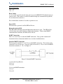
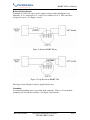
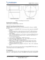
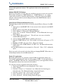
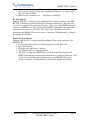
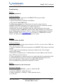
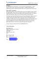
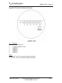
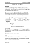
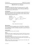
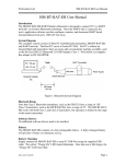
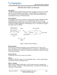
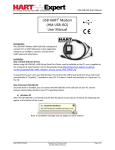
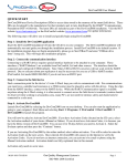
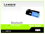
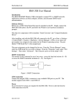
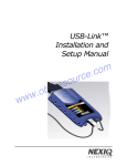
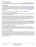
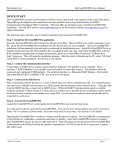
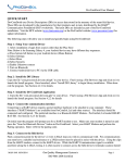
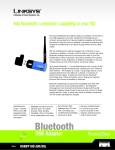
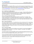
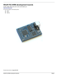
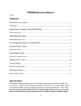
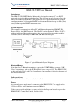
HM-BT-VIN User Manual
HM-BT-VIN User Manual
Introduction
The HM-BT-VIN HART Modem, Bluetooth is designed to connect PC’s to HART
networks via wireless Bluetooth technology. The explosion proof enclosure allows the
unit to be mounted permanently in the plant. The user’s application software can then
configure, monitor, and document HART based instrumentation from up to 100ft (33m)
away without opening HART instrument covers.
System Diagram
The complete system consists of Host PC with Bluetooth transmitter, HM-BT-VIN,
Power Supply, and HART network. The Host PC can be a Pocket PC PDA. For PC’s
without an integral Bluetooth transmitter, there are many add-on transmitter modules
available, such as the Linksys USBBT100, USB Bluetooth Adapter.
Figure 1. Typical Bluetooth System Diagram
Bluetooth Range
Note that Class 1 Bluetooth transmitters, such as the USBBT100 have a range of 100’.
Class 2 transmitters, such as the HP IPAQ PDA, have a range of 25’. The HM-BT-VIN
works with both Class 1 and Class 2 transmitters, but operation is limited to the range of
the master transmitter.
Software Drivers
No additional software drivers need to be installed.
Power
An external power supply must be connected to the HM-BT-VIN. The supply can be
12Vdc to 36Vdc, with a minimum current of 500mA.
Under some special conditions, the same supply for the Loop can be used to power the
HM-BT-VIN. Contact ProComSol, Ltd for details.
MAN-1006 1/06/2010
Our Quality Management System is
ISO 9001:2008 Certified
Page 1
HM-BT-VIN User Manual
Power Connection:
J1-1 – V+
J1-2 – VReset Switch
A reset switch is provided on the front panel to reset the HM-BT-VIN without having to
remove power. This switch is useful for troubleshooting any communication problems.
It is not needed for normal use.
Press and hold the switch for 5 seconds to perform a reset.
Power LED
When the unit is powered, the Red LED will be on.
Bluetooth Activity LED
This Blue LED will flicker when the Bluetooth connection is open. The LED will be
solid on when successfully linked to a Bluetooth transmitter. Under normal HART
communication conditions, the LED will be solid on.
HART Connections
There are several ways to make the HART connection. Your specific situation will
determine the best connection method to use to reduce installation time.
Standard HART Connection
The front panel terminals J1-3 and J1-4 are the HART connections. The modem can be
connected in one of two ways: across the loop load resistor (A – B) or across the HART
transmitter terminals (C – D). See Figure 2.
Figure 2. Standard HART Connections
1. Across the Loop Resistor
J1-3 to A
J1-4 to B
2. Or, to the HART transmitter
J1-3 to C
J1-4 to D
MAN-1006 1/06/2010
Our Quality Management System is
ISO 9001:2008 Certified
Page 2
HM-BT-VIN User Manual
Reduced Wiring Feature
Terminals J1-5 and J1-6 can be used to reduce wiring to make installation easier.
Internally, J1-5 is connected to J1-3, and J1-6 is connected to J1-4. This can reduce
wiring in two ways. See Figures 3 and 4.
Figure 3. Reduced HART Wiring
Figure 4. Loop Resistor in HM-BT-VIN
The loop resistor in Figure 4 must be supplied by the user.
Grounding
An external grounding screw is provided on the enclosure. There is also an internal
grounding screw inside the enclosure. See Figure 5 for locations.
MAN-1006 1/06/2010
Our Quality Management System is
ISO 9001:2008 Certified
Page 3
HM-BT-VIN User Manual
Figure 5. Grounding Screw Locations
Explosion Proof Applications
Install conduit seals within 50mm of enclosure.
Initial PC Setup/ Bluetooth Modem Discovery
The following procedure must be done at least once for the PC to “Discover” the HMBT-VIN.
1. Apply power to the HM-BT-VIN. It does not need to be connected to the HART
network.
2. Run the Bluetooth driver software that came with your PC or Bluetooth adapter
(ie Linksys). There is typically a Bluetooth icon on the system tray that can be
double clicked.
3. Select “Find Bluetooth Devices” or “Site Survey” to locate any Bluetooth devices
in the area. You could also search for services. Search for “Serial Services” to
also locate Bluetooth devices.
4. A device labeled “HART Modem” should be discovered.
5. Double click on the “HART Modem” icon. The available serial service will
appear as “ZV-SPP”, and say it is not connected.
6. Double click on “ZV-SPP”. The Bluetooth connection will be made and the
assigned COM port will be reported. This is typically COM8. Note this port
number for your application software.
7. Some Bluetooth drivers may prompt for a “Passcode”. Enter “1234”, without the
quotes.
Discovery needs to be repeated only when adding or changing HM-BT-VIN modems, or
when multiple modems are in the Bluetooth area.
PC Applications
Start your PC application and set the com port setting to use the com port reported during
Discovery. Use the application as normal. The HM-BT-VIN looks like a normal RS232
MAN-1006 1/06/2010
Our Quality Management System is
ISO 9001:2008 Certified
Page 4
HM-BT-VIN User Manual
device to the application software. The application software does not need to be
modified.
Multiple HM-BT-VIN Modems
When several modems are in the same area, the Discovery process needs to be repeated.
The modems will appear as “HART Modem (1)”, “HART Modem (2)”, etc. It may
require trial and error to determine which modem is connected to the desired HART
network. Once determined, you can change the name of the HART Modem icons to
match your system.
Initial Pocket PC/Bluetooth Modem Discovery
The following procedure must be done at least once for the PDA to “Discover” the HMBT-VIN.
1. Apply power to the HM-BT-VIN. It does not need to be connected to the HART
network.
2. Run the wireless setup utility and enable Bluetooth.
3. Select “Manage” to bring up the “Bluetooth Manager”.
4. Select “New” to start the “Connection Wizard”. A list of Bluetooth device types
should appear.
5. Select “Explore Bluetooth Device”. This will start a site survey to look for
available Bluetooth devices
6. A device labeled “HART Modem” should be discovered.
7. Select the “HART Modem” icon. The available serial service will appear as “ZVSPP”.
8. Highlight “ZV-SPP” and select “Next”. Then select “Finish”
9. Double click on the “HART Modem: ZV-SPP” icon. The Bluetooth connection
will be made.
10. Some Bluetooth drivers may prompt for a “Passcode”. Enter “1234”, without the
quotes.
Discovery needs to be repeated only when adding or changing HM-BT-VIN modems, or
when multiple modems are in the Bluetooth area.
Pocket PC Applications
Bluetooth serial modems are generally assigned COM8 for application software use.
Start your PC application and set the com port setting to COM8. Use the application as
normal. The HM-BT-VIN looks like a normal RS232 device to the application software.
The application software does not need to be modified.
To verify the com port assignment, follow this procedure.
1. Tap the top of the PDA screen to bring up the “Start” menu.
2. Select “Settings”.
3. Under the “Systems” or “Connections” tab, a Bluetooth icon should appear.
Select this icon. The “Bluetooth Settings” menu should appear.
4. Select the “Services” tab. A list of services will appear.
5. Select “Serial Port”. The service settings will appear.
6. Select “Advanced”. The Port Settings menu will appear.
MAN-1006 1/06/2010
Our Quality Management System is
ISO 9001:2008 Certified
Page 5
HM-BT-VIN User Manual
7. The Com port setting is shown under “Outbound COM port:” As stated earlier,
this value will be COM 8.
8. Make sure the “Default device…” check box is Unchecked.
PC Test Software
Program “HM Test” is included on the installation CD to test the operation of the HMBT-VIN. Launch the program from the CD or from the installed icon. Enter the com
port that was assigned to the modem by Windows. Then select “Poll HART Network” to
connect to a HART device. The program sends HART Command 0 to determine what
transmitters are connected to the loop. The “Status” box will indicate successful
operation of the HM-BT-VIN in your system. Consult the “Troubleshooting” section of
this manual if test failure.
Pocket PC Test Software
Program “HM Test CE” is included on the installation CD to test the operation of the
HM-BT-VIN.
1. Use the ActiveSync utility to load this program on to your Pocket PC.
2. Start “File Explorer”.
3. Navigate to the “My Device” directory.
4. Tap “HM Test CE” to launch the program.
5. Tap “Poll” to search for a HART device on the network. The program sends
HART Command 0 to determine what transmitters are connected to the loop. The
“Status” box will indicate successful operation of the HM-BT-VIN in your
system. Consult the “Troubleshooting” section of this manual if test failure.
MAN-1006 1/06/2010
Our Quality Management System is
ISO 9001:2008 Certified
Page 6
HM-BT-VIN User Manual
Troubleshooting
Problem:
Will not communicate
Verify the following:
1. Com port number in application is the HM-BT-VIN com port number.
2. Loop power supply is on.
3. Loop resistance between 250 ohms and 1Kohms.
4. Loop current within HART limits.
5. If multi drop configuration, all transmitters in loop have unique addresses.
6. HM-BT-VIN HART connections across loop resistor or across transmitter terminals.
7. Modem power is on and the Red power LED is illuminated.
8. Perform the “Discovery” procedure again and verify a connection can be made.
9. If using the Linksys USBBT100, verify the Linksys Bluetooth driver is installed and
not the Windows Bluetooth driver. There is a known issue with the Linksys install and
Windows XP SP2. Go to www.linksys.com and search for “USBBT100” for details.
10. Press and hold the front panel Reset button for 5 seconds.
Problem:
Communications unreliable
Verify the following:
1. You are in radio range of the master transmitter. For Class 1 master devices 100 ft, for
Class 2 master devices, 25 ft.
2. Vary the orientation of the master transmitter or the HM-BT-VIN to improve radio link
strength.
3. Power supply meets the minimum requirements outlined in the “Power Supply”
section of this manual.
4. Transmitter not in Burst mode. Communications can occur in Burst mode, but more
retries will be necessary for success.
5. In some applications, a connection can be lost, which looks like a communication lockup. Perform the Discovery process again to reestablish the link without the need to
restart your application. When a link is lost the Blue LED will flash.
6. Press and hold the front panel Reset button for 5 seconds.
Problem:
Will not communicate with Cornerstone
Perform the following:
1. In directory “CSCONFIG/DB”, open file “CSLOCAL.INI”.
2. Search for “[RDLS2]” without the quotes.
3. Change “Debug=0” to “Debug=8”, again without the quotes.
4. Save the file.
MAN-1006 1/06/2010
Our Quality Management System is
ISO 9001:2008 Certified
Page 7
HM-BT-VIN User Manual
Warranty
The HM-BT-VIN is warranted for 1 year for materials and workmanship. Contact
Support at ProComSol, Ltd if having any problems. An RMA (Return Material
Authorization) number obtained from ProComSol, Ltd is required on all returned items.
Notice of FCC Compliance
This product contains a radio module that has been tested and found to comply with the
FCC Part15 Rules. These limits are designed to provide reasonable protection against
harmful interference in approved installations. This equipment generates, uses, and can
radiate radio frequency energy and, if not installed and used in accordance the
instructions, may cause harmful interference to radio communications. However, there is
no guarantee that interference will not occur in a particular installation. This device
complies with part 15 of the FCC Rules. Operation is subject to the following two
conditions: (1) This device may not cause harmful interference, and (2) this device must
accept any interference received, including interference that may cause undesired
operation. Modifications or changes to this equipment not expressly approved by
ProComSol, Ltd may void the user’s authority to operate this equipment.
Contains Transmitter Module FCC ID: S22BTMODULE-CL2
Contact Information
ProComSol, Ltd
Process Communications Solutions
13000 Athens Ave
Suite 104G
Lakewood, OH 44107
USA
Phone: 216.221.1550
Fax: 216.221.1554
Email: [email protected]
[email protected]
Web: www.procomsol.com
MAN-1006 1/06/2010
Our Quality Management System is
ISO 9001:2008 Certified
Page 8
HM-BT-VIN User Manual
Appendix I. Front Panel Connector Diagram
J1
1
2
3
4
5
6
Function
V+, Power Supply In
V-, Power Supply Ground
HART In+
HART InHART In+
HART In-
Notes:
1. Terminals 3 and 5 are connected together internally
2. Terminals 4 and 6 are connected together internally
MAN-1006 1/06/2010
Our Quality Management System is
ISO 9001:2008 Certified
Page 9