1
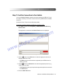
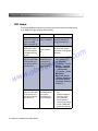
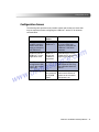
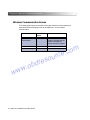
USB-Link™ Installation and Setup Manual w o . ww s e r d b m o c . e c r ou USB-Link™ IDSC Holdings LLC retains all ownership rights to the USB-Link and its documentation. The USB-Link source code is a confidential trade secret of IDSC Holdings LLC. You may not decipher or decompile USB-Link software, develop source code for the USB-Link, or knowingly allow others to do so. The USB-Link and its documentation may not be sublicensed or transferred without the prior written consent of IDSC Holdings LLC. This manual, as well as the software it describes, is furnished under license and may only be used or copied in accordance with the terms of such license. The content of this manual is furnished for informational use only, is subject to change without notice, and should not be construed as a commitment by IDSC Holdings LLC. IDSC Holdings LLC assumes no responsibility or liability for any errors or inaccuracies that may apear in this book. Except as permitted by such license, no part of this publication may be reproduced, or transmitted, in any form or by any means, electronic, mechanical, or otherwise, without the prior written permission of IDSC Holdings LLC. NEXIQ Technologies is a trademark of IDSC Holdings LLC. © 2007 IDSC Holdings LLC. All rights reserved. All other marks are trademarks or registered trademarks of the respective holders. Pictures for illustration purposes only. Specifications are subject to change without notice. m o c . e c r ou www.nexiq.com The device complies with Part 15 of the FCC Rules. Operation is subject to the following two conditions: (1) this device may not cause harmful interference, and (2) this device must accept any interference received, including interference that may cause undesired operation. This device contains FCC-ID-POOWML-C30XX. s e r d b o . ww Approved in accordance to R&TTE directive transmitter module marked by “CE product label”, manufactured by MITSUMI Incorporated to OEM product. w Part No.1400-358 Revised 09/11/2007 Safety Information For your safety, read this manual thoroughly before operating your USB-Link™ unit. Your USB-Link™ unit is intended for use by properly trained, skilled professional heavyduty technicians. The safety messages presented below and throughout this user’s manual are reminders to the operator to exercise extreme care when using this test instrument. There are many variations in procedures, techniques, tools, and parts for servicing vehicles, as well as in the skill of the individual doing the work. Because of the vast number of test applications and variations in the products that can be tested with this instrument, we cannot possibly anticipate or provide advice or safety messages to cover every situation. It is the heavy-duty technician’s responsibility to be knowledgeable of the system being tested. It is essential to use proper service methods and test procedures and to perform tests in an appropriate and acceptable manner that does not endanger your safety, the safety of others in the work area, or vehicle or equipment being tested. c r ou m o c . e It is assumed the operator has a thorough understanding of vehicle systems before using the USB-Link™ unit. Understanding of these system principles and operating theories is necessary for competent, safe and accurate use of this instrument. s e r d b Before using the USB-Link™ unit, always refer to and follow safety messages and applicable test procedures provided by the manufacturer of the vehicle or equipment being tested. Use equipment only as described in this manual. o . ww Read, understand and follow all safety messages and instructions in this manual and on the test equipment. Safety messages in this section of the manual contain a signal word with a three-part message and an icon. The signal word indicates the level of the hazard in a situation. w Safety Information Safety Message Conventions Safety messages are provided to help prevent personal injury and equipment damage. All safety messages are introduced by a signal word indicating the hazard level. Indicates an imminently hazardous situation which, if not avoided, will result in death or serious injury to the operator or to bystanders. Indicates a potentially hazardous situation which, if not avoided, could result in death or serious injury to the operator or to bystanders. Indicates a potentially hazardous situation which, if not avoided, may result in moderate or minor injury to the operator or to bystanders. m o c . e c r ou Indicates a situation which, if not avoided, may result in damage to the test equipment or vehicle. Safety messages contain three different type styles. • Normal type states the hazard. s e r d b • Bold type states how to avoid the hazard. • Italic type states the possible consequences of not avoiding the hazard. o . ww An icon, when present, gives a graphical description of the potential hazard. Example: w Risk of unexpected vehicle movement. • Block drive wheels before performing a test with engine running. A moving vehicle can cause injury. Important Safety Instructions Risk of entanglement. • Do not allow cables to hang in such a way that they may become entangled with operator or driving controls. Cable entanglement can cause interference with driving and can cause injury. Risk of electric shock. • Do not exceed voltage limits between inputs as indicated on the rating label. • Use extreme caution when working with circuits that have greater than 60 volts DC or 25 volts AC. iv USB-Link™ Installation and Setup Manual Important Safety Instructions Risk of explosion. • Do not use this system in environments where explosive vapor may collect, such as in below-ground pits, confined areas, or areas that are less than 18 inches above the floor. Explosion can cause injury. Risk of poisoning. • Use this equipment in locations with mechanical ventilation providing at least four air changes per hour. Engine exhaust contains odorless lethal gas. • Route exhaust outside while testing with engine running. Poisoning can result in death or serious injury. Risk of accident. • Two people should be in the vehicle when driving on road, one to drive and the other to attend to the equipment. Accidents can occur when attention is not solely given to driving. Risk of unexpected vehicle movement. • Block drive wheels before performing a test with engine running. • Unless instructed otherwise, set parking brake and put gear selector in neutral or park. • If vehicle has an automatic parking brake release, disconnect release mechanism for testing and reconnect when finished. • Do not leave a running engine unattended. A moving vehicle can cause injury. s e r d b o . ww w m o c . e c r ou Save These Instructions USB-Link™ Installation and Setup Manual v Safety Information s e r d b o . ww w vi m o c . e c r ou USB-Link™ Installation and Setup Manual Safety Information ............................................iii Safety Message Conventions ................................................. iv Important Safety Instructions .................................................. iv Chapter 1: Introducing the USB-Link™ ................................1 Product Specifications .............................................................2 System Requirements .............................................................3 USB-Link™ Components ........................................................4 m o c . e c r ou Communication Options: Wireless or Wired? ..........................5 Wireless Connection ...................................................................... 6 Wired Connection .......................................................................... 7 s e r d b Chapter 2: Installation and Bluetooth Configuration ..............9 o . ww Installation Process Flowchart ...............................................10 Outline of Installation Process ...............................................11 w Step 1: Install the USB-Link™ Drivers and Utilities ............... 12 Instructions for Windows® 2000 and XP Users .......................... 12 Instructions for Vista® Users ........................................................ 22 USB-Link™ Installation and Setup Manual vii Step 2: Choose Your Connection ................................................33 Step 3: Install the Bluetooth Adapter ...........................................35 Step 4: Install the Bluetooth Drivers ............................................36 Additional Steps for Windows XP SP-2 .......................................44 Configure the Bluetooth Environment .........................................52 Chapter 3: Preparing to Use the USB-Link™ ........................... 55 Step 5: Connect the USB-Link™ to a Vehicle .............................56 m o c . e c r ou Wireless Connection .......................................................................... 57 Wired Connection Using a USB Cable ............................................... 58 Step 6: Use the Bluetooth Connection Utility ..............................60 Step 7: Test the Connection to the Vehicle .................................65 s e r d b Step 8: Setting Up Diagnostic PC Applications ...........................68 Allison DOC™ for Fleets (1000/2000) ................................................ 68 Allison DOC™ for Fleets (3000/4000) ................................................ 68 o . ww Bendix ABS Diagnostics ..................................................................... 69 Caterpillar Electronic Technician ........................................................ 69 w Cummins Insite ................................................................................... 70 Detroit Diesel Diagnostic Link ............................................................ 71 Eaton Service Ranger ........................................................................ 71 International INTUNE ......................................................................... 72 International Master Diagnostics (3BX, DLC, DLC II) ........................ 72 Meritor WABCO ABS ......................................................................... 72 viii USB-Link™ Installation and Setup Manual Chapter 4: USB-Link™ Troubleshooting Information ............... 73 LED Issues ..................................................................................74 Configuration Issues ....................................................................75 Wireless Communication Issues .................................................76 Appendix A: Warranty and Service .......................................... 77 m o c . e c r ou Exclusive Warranty ......................................................................78 Exclusive Remedy .......................................................................79 Return Materials Authorization (RMA) .........................................80 s e r d b Return of Goods Policy ................................................................82 Return Goods Authorization (RGA) Procedure ...........................83 w o . ww USB-Link™ Installation and Setup Manual ix s e r d b o . ww w x m o c . e c r ou USB-Link™ Installation and Setup Manual 1 Introducing the USBLink™ m o c . e c r ou uProduct Specifications, page 2 uSystem Requirements, page 3 uUSB-Link™ Components, page 4 uCommunication Options: Wireless or Wired?, page 5 s e r d b The USB-Link™ is a hardware device that enables service bay personal computers ® w o . ww (PCs) to retrieve vehicle information using either Bluetooth wireless technology or a more traditional cable connection. Once configured, the USB-Link™ interfaces with your PC, enabling you to use specific PC applications to perform vehicle diagnostics. This chapter introduces the USB-Link™ and provides details regarding the communication modes available to you to interface with your PC. USB-Link™ Installation and Setup Manual 1 Chapter 1 • Introducing the USB-Link™ Product Specifications The USB-Link™ is configured with the following specifications: Feature Data Physical Dimensions 5.86" x 3.02" x 1.78" (149 mm x 77 mm x 45 mm) Weight 4.6 oz. (0.13 kg) Power Requirements 10 - 32 VDC @ 350 mA maximum Operating Temperature 0 to +70 °C Vehicle Protocols Supported s e r d b o . ww w 2 m o c . e c r ou • J1708/J1587 • J1939 • CAN (125K, 250K, or 500K) (Dual CAN supported) • J2284 CAN (125K, 250K, or 500K) • ALDL Pass-through • ALDL 8192 • ALDL 9600 • OBDII • ISO 9141 • ISO 14230 (KWP2000) • J1850 (PWM, VPM, or Allison) • J1708 • IESCAN (required for Allison) USB Communication USB Device, version 1.1 Wireless Communication Bluetooth Class 1 adapter (up to 100 m range) Wired Communication USB cable 15 ft. (5 m) maximum PC Driver TMC RP1210A compliant Vehicle Connector DB15F USB Connector Type B jack USB-Link™ Installation and Setup Manual - System Requirements System Requirements Be aware of the following system requirements: Component IBM PC-compatible computer Requirement • 1GHz processor or more • RAM: 256MB or more (512MB recommended) • USB port, version 1.1 or higher Operating system Windows 2000, XP (Service Pack 1 or 2), Vista® Bluetooth adapter • Bluetooth serial port capability • Must support WIDCOMM® drivers, 1.4x and higher The USB-Link™ has been qualified with the following Class 1 adapters: m o c . e c r ou s e r d b - Linksys USBBT100 (preferred) - Belkin F8T001 w o . ww USB-Link™ Installation and Setup Manual 3 Chapter 1 • Introducing the USB-Link™ USB-Link™ Components The following illustration details each of the USB-Link™ components: s e r d b o . ww w m o c . e c r ou Figure 1.1 USB-Link™ Components a chapter’s first page. The page’s layout isements (e.g., ChapIntro, Body Text, Bullets, etc.), not headings. Headings on this page produce alignment If the introduction paragraphs a chapter’s first page. The page’s layout is designed to present body elements (e.g., ChapIntro, Body Text, Bullets, etc.), not headings. Headings on this page produce alignment If the introduction paragraphs 4 USB-Link™ Installation and Setup Manual - Communication Options: Wireless or Wired? Communication Options: Wireless or Wired? Prior to using the USB-Link™, you need to decide how you want the unit to communicate with your PC. There are two options: • Wireless connection to the PC using Bluetooth A wireless connection provides the advantage of untethered communication. m o c . e c r ou s e r d b o . ww Figure 1.2 Wireless Connection w • Wired connection to the PC using a USB cable A wired connection provides the advantage of faster data throughput. Figure 1.3 Wired Connection USB-Link™ Installation and Setup Manual 5 Chapter 1 • Introducing the USB-Link™ Wireless Connection Wireless connectivity provides untethered operation, and that’s a bonus in a busy service bay. USB-Link™ uses Bluetooth to provide this wireless communication between the USB-Link™ and your PC. NOTE: i The USB-Link™ does not support Integrated Bluetooth. If your PC has Integrated Bluetooth, your system has Bluetooth drivers installed and a built-in Bluetooth transceiver. You must uninstall Integrated Bluetooth and its Bluetooth drivers prior to proceeding with the USB-Link™ installation process. m o c . e c r ou If your PC does not have Integrated Bluetooth, then you are clear to proceed with the USB-Link™ installation process as documented in this manual: • Install Bluetooth drivers • Install an external Bluetooth transceiver (i.e., an adapter) • Configure a basic Bluetooth environment — For detailed information on installing Bluetooth drivers and configuring a basic Bluetooth environment, refer to Chapter 2: Installation and Bluetooth Configuration, later in this manual. s e r d b o . ww w 6 • Run the NEXIQ Bluetooth Connection Utility — For information on running the NEXIQ Bluetooth Connection Utility, refer to Chapter 3: Preparing to Use the USB-Link™, later in this manual. — USB-Link™ is intended for diagnostic use, for example, retrieving trouble codes. By nature, Bluetooth has limited bandwidth and latency when compared to wired solutions. This may result in dropped messages in situations requiring high bandwidth. USB-Link™ Installation and Setup Manual - Communication Options: Wireless or Wired? Wired Connection Using a USB connection to the PC is highly recommended when diagnosing heavily-loaded CAN/J1939 buses. By nature, Bluetooth has less bandwidth than USB, which can result in dropped messages in situations requiring high bandwidth. ECU reprogramming typically requires both high throughput and critical timing, and should always use a USB-to-PC wired connection. Wired communication between the USB-Link™ and your PC requires a USB cable. m o c . e c r ou s e r d b Figure 1.4 15 ft. USB Cable included with your USB-Link™ w o . ww USB-Link™ Installation and Setup Manual 7 Chapter 1 • Introducing the USB-Link™ s e r d b o . ww w 8 m o c . e c r ou USB-Link™ Installation and Setup Manual 2 Installation and Bluetooth Configuration s e r d b o . ww w m o c . e c r ou uStep 1: Install the USB-Link™ Drivers and Utilities, page 12 uInstructions for Windows® 2000 and XP Users, page 12 uInstructions for Vista® Users, page 22 uStep 2: Choose Your Connection, page 33 uStep 3: Install the Bluetooth Adapter, page 35 uStep 4: Install the Bluetooth Drivers, page 36 uAdditional Steps for Windows XP SP-2, page 44 uConfigure the Bluetooth Environment, page 52 T his chapter provides instructions for installing NEXIQ drivers and utilities, installing the required Bluetooth® drivers, installing a Bluetooth adapter, and configuring a basic Bluetooth environment. It also provides special instructions for Vista® users. USB-Link™ Installation and Setup Manual 9 Chapter 2 • Installation and Bluetooth Configuration Installation Process Flowchart Install NEXIQ Drivers Yes W ireless? Install B T Adapter Install BT Drivers m o c . e c r ou S ervice Pack 2 ? Yes No s e r d b Update BT Drivers No o . ww C onnect to Vehicle (Physical) w C onfigure B T Environm ent Connect to Vehicle (P hysical) Run C onnect Utility Test the C onnection S et U p Diagnostic A pplications Figure 2.1 Process Flowchart 10 USB-Link™ Installation and Setup Manual - Outline of Installation Process Outline of Installation Process Step 1: Install the NEXIQ USB-Link™ drivers and utilities. Step 2: Choose your connection (wired or wireless). If you chose a wired connection, move on to complete steps 5, 7, and 8 only. Step 3: If you chose a wireless connection, install the Bluetooth adapter (e.g., the Linksys dongle). Step 4: Install the drivers for the Bluetooth adapter you are using. Only if you are installing an adapter other than the Linksys: m o c . e c r ou • If you are running Windows XP Service Pack 2, update the Bluetooth drivers you installed in Step 4. If, however, you are not running Windows XP SP-2, skip this procedure and move on to the next bullet. • Use the Bluetooth Configuration Wizard to configure a basic Bluetooth environment. s e r d b Step 5: o . ww Step 6: w Step 7: Step 8: Connect the USB-Link™ to the vehicle. Use the NEXIQ Bluetooth Connection Utility to select a USB-Link™ and test the signal strength. Use the NEXIQ Device Tester to test the connection between the USBLink™ and the vehicle. Set up diagnostic PC applications that apply to your local environment for use with the USB-Link™. USB-Link™ Installation and Setup Manual 11 Chapter 2 • Installation and Bluetooth Configuration Step 1: Install the USB-Link™ Drivers and Utilities Instructions for Windows® 2000 and XP Users i If you are running Vista®, please refer to the special instructions for Vista users on page 22 of this manual. Prior to using the USB-Link™ it is necessary to install the required NEXIQ device drivers and utilities on your PC or laptop. These device drivers are compatible with Microsoft® Windows® 2000 and XP. IMPORTANT: ä Remember, if you are running Windows XP on your PC, you must have m o c . e c r ou Administrator security rights and be logged in as “Admin” to successfully complete the installation process outlined in this manual. i If you have questions about using this product, contact NEXIQ Technical Support at (800) 639-6774, or send us an e-mail at [email protected]. s e r d b To install the device drivers and utilities: 1 Close all programs and insert the NEXIQ USB-Link Drivers CD into your PC’s CD-ROM drive. o . ww w 12 USB-Link™ Installation and Setup Manual - Step 1: Install the USB-Link™ Drivers and Utilities The installation begins by displaying the Welcome! screen. m o c . e c r ou s e r d b o . ww Figure 2.2 Installation Welcome! Screen w —If the program does not automatically start, access your CD-ROM drive through My Computer and double-click the SETUP.EXE file. 2 Read the information displayed on the Welcome! screen, and click Next. USB-Link™ Installation and Setup Manual 13 Chapter 2 • Installation and Bluetooth Configuration The Copyright Notice screen is displayed. s e r d b m o c . e c r ou Figure 2.3 Copyright Notice Screen o . ww 3 Read all the information on this screen, then click I Accept. w 14 USB-Link™ Installation and Setup Manual - Step 1: Install the USB-Link™ Drivers and Utilities NOTE: i If you do not agree to the terms, click I Decline. A message is displayed prompting you to confirm exiting the installation. Click EXIT SETUP. The Backup Replaced Files? screen is displayed. s e r d b o . ww w m o c . e c r ou Figure 2.4 Backup Replaced Files? Screen 4 Do one of the following: —Click Yes if you wish to back up copies of files replaced during the installation (recommended). —Click No if you do not wish to back up files. 5 Click Next to continue. USB-Link™ Installation and Setup Manual 15 Chapter 2 • Installation and Bluetooth Configuration If you chose to back up replaced files, the installation program requests a location to store the files. m o c . e c r ou s e r d b Figure 2.5 Select Backup Directory Screen o . ww 6 Do one of the following: w —To accept the default directory, click Next and proceed to Step 7 (recommended). —To select a different directory, click Browse... At the bottom of the screen, select the desired drive letter from the dropdown list. Double-click each directory to add to the path. Click OK to proceed. The program returns to the Select Backup Directory screen. Confirm the destination, then click Next. 16 USB-Link™ Installation and Setup Manual - Step 1: Install the USB-Link™ Drivers and Utilities The Select Components screen is displayed. m o c . e c r ou s e r d b Figure 2.6 Select Components screen o . ww 7 Check the check box to install J2534 support for HINO Diagnostic eXplorer. 8 Click Next to continue. w USB-Link™ Installation and Setup Manual 17 Chapter 2 • Installation and Bluetooth Configuration 9 Wait for the Ready to Install! screen to appear. s e r d b Figure 2.7 Ready to Install! Screen o . ww NOTE: m o c . e c r ou i Be sure to disconnect all RP1210A adapters currently connected to the PC w before proceeding with the installation. 10 Do one of the following: 18 USB-Link™ Installation and Setup Manual - Step 1: Install the USB-Link™ Drivers and Utilities —Click Next to proceed with the installation. —Click Back to step backward through previous screens. —Click Cancel to stop the installation. A dialog box displaying a status bar is displayed indicating percentage complete. Figure 2.8 Status Bar m o c . e c r ou s e r d b If Microsoft®.NET Framework is not found on your PC, the following dialog box is displayed. w o . ww Figure 2.9 .NET Framework Dialog Box 11 Click OK, and follow the prompts to install the .NET software. Once the .NET installation is complete, the following message is displayed: Installation of Microsoft .NET Framework 1.1 is complete. 12 Click OK to continue. USB-Link™ Installation and Setup Manual 19 Chapter 2 • Installation and Bluetooth Configuration The following dialog is displayed: Figure 2.10 Acrobat Reader Search Dialog If the version of the Adobe Acrobat® Reader installed on your PC is up-todate, a dialog is displayed informing you of this fact. Click OK, and move on to Step 14 (pg. 21). m o c . e c r ou NOTE: i The Adobe Acrobat® Reader is required to view this Installation Manual s e r d b electronically as a portable document format (PDF) file. If, however, your PC requires installation of the Adobe Acrobat® Reader, the o . ww w 20 USB-Link™ Installation and Setup Manual - Step 1: Install the USB-Link™ Drivers and Utilities following screen is displayed. m o c . e c r ou s e r d b o . ww Figure 2.11 Acrobat Reader Installation Screen w 13 Click Next to accept the default (Yes), and follow the prompts. 14 Wait for the Installation Completed! screen to appear, then click Finish. Figure 2.12 Installation Completed! Screen USB-Link™ Installation and Setup Manual 21 Chapter 2 • Installation and Bluetooth Configuration A message appears prompting you to restart the PC. m o c . e c r ou Figure 2.13 Restart Prompt 15 Click OK to restart the PC. 16 Once the PC restarts, remove the installation CD from the CD-ROM drive. s e r d b Move on to “Step 2: Choose Your Connection,” later in this chapter. Instructions for Vista® Users o . ww w Prior to using the USB-Link™ it is necessary to install the required NEXIQ device drivers and utilities on your PC or laptop. These device drivers are compatible with Microsoft® Windows® 2000, XP, and Vista®. IMPORTANT: ä You must have Administrator security rights and be logged in as “Admin” to successfully complete the installation process outlined in this manual. NOTE: i If you have questions about using this product, contact NEXIQ Technical Support at (800) 639-6774, or send us an e-mail at [email protected]. To install the device drivers and utilities: 1 Close all programs and insert the NEXIQ USB-Link Drivers CD into your laptop’s CD-ROM drive. 22 USB-Link™ Installation and Setup Manual - Step 1: Install the USB-Link™ Drivers and Utilities The AutoPlay window opens. 2 Click Install or run program (i.e., “Run setup.exe Published by IDSC Holdings LLC”). 3 Click Continue. The installation begins by displaying the Welcome! screen. s e r d b o . ww w m o c . e c r ou Figure 2.14 Installation Welcome! Screen —If the program does not automatically start, access your CD-ROM drive through Start 4 Computer and double-click the SETUP.EXE file. 4 Read the information displayed on the Welcome! screen, and click Next. USB-Link™ Installation and Setup Manual 23 Chapter 2 • Installation and Bluetooth Configuration The Copyright Notice screen is displayed. s e r d b m o c . e c r ou Figure 2.15 Copyright Notice Screen o . ww 5 Read all the information on this screen, then click I Accept. w 24 USB-Link™ Installation and Setup Manual - Step 1: Install the USB-Link™ Drivers and Utilities NOTE: i If you do not agree to the terms, click I Decline. A message is displayed prompting you to confirm exiting the installation. Click EXIT SETUP. The Backup Replaced Files? screen is displayed. s e r d b o . ww w m o c . e c r ou Figure 2.16 Backup Replaced Files? Screen 6 Do one of the following: —Click Yes if you wish to back up copies of files replaced during the installation (recommended). —Click No if you do not wish to back up files. 7 Click Next to continue. USB-Link™ Installation and Setup Manual 25 Chapter 2 • Installation and Bluetooth Configuration If you chose to back up replaced files, the installation program requests a location to store the files. m o c . e c r ou s e r d b Figure 2.17 Select Backup Directory o . ww 8 Do one of the following: w —To accept the default directory, click Next and proceed to Step 9 (recommended). —To select a different directory, click Browse... At the bottom of the screen, select the desired drive letter from the dropdown list. Double-click each directory to add to the path. Click OK to proceed. The program returns to the Select Backup Directory screen. Confirm the destination, then click Next. 26 USB-Link™ Installation and Setup Manual - Step 1: Install the USB-Link™ Drivers and Utilities The Select Components screen is displayed. m o c . e c r ou s e r d b Figure 2.18 Select Components screen o . ww 9 Check the check box to install J2534 support for HINO Diagnostic eXplorer. 10 Click Next to continue. w USB-Link™ Installation and Setup Manual 27 Chapter 2 • Installation and Bluetooth Configuration 11 Wait for the Ready to Install! screen to appear. s e r d b m o c . e c r ou Figure 2.19 Ready to Install! Screen o . ww NOTE: i Be sure to disconnect all RP1210A adapters currently connected to the PC w before proceeding with the installation. 12 Do one of the following: 28 USB-Link™ Installation and Setup Manual - Step 1: Install the USB-Link™ Drivers and Utilities —Click Next to proceed with the installation. —Click Back to step backward through previous screens. —Click Cancel to stop the installation. A Windows Security warning is displayed. m o c . e c r ou s e r d b Figure 2.20 Windows Security Warning 13 Click on the check box labeled Always trust software from “Jungo LTD”. o . ww 14 Click Install. w Figure 2.21 Installation Window 15 Wait while the driver package is installed. This could take a few seconds. USB-Link™ Installation and Setup Manual 29 Chapter 2 • Installation and Bluetooth Configuration Windows Security displays the following window: m o c . e c r ou Figure 2.22 Windows Security Warning 16 Click Install this driver software anyway. s e r d b 17 Wait while the drivers are installed. o . ww w 30 USB-Link™ Installation and Setup Manual - Step 1: Install the USB-Link™ Drivers and Utilities The following dialog is displayed: Figure 2.23 Acrobat Reader Search Dialog If your PC requires installation of the Adobe Acrobat® Reader, the following screen is displayed. s e r d b o . ww w m o c . e c r ou Figure 2.24 Acrobat Reader Installation Screen 18 Click Next to accept the default (Yes), and follow the prompts. The Adobe Reader - Setup window is displayed. 19 Click Next, and follow the Adobe Wizard prompts. USB-Link™ Installation and Setup Manual 31 Chapter 2 • Installation and Bluetooth Configuration 20 When the Adobe installation is complete, click Finish to exit the Wizard and continue with the remainder of the installation process. 21 When the Installation Completed! screen appears, click Finish. m o c . e c r ou s e r d b Figure 2.25 Installation Completed! Screen o . ww A message appears prompting you to restart the PC. w Figure 2.26 Restart Prompt 22 Click OK to restart the PC. 23 Once the PC restarts, remove the installation CD from the CD-ROM or DVDROM drive. Move on to “Choose Your Connection,” next in this manual. 32 USB-Link™ Installation and Setup Manual - Step 2: Choose Your Connection Step 2: Choose Your Connection You have two options for connecting the USB-Link™ to a PC or laptop computer. Choose one of the following options. Both have advantages. • Wired connection using a 15 ft. USB cable The advantage of a wired connection is faster throughput (e.g., you want to use the USB-Link™ for ECU reprogramming). m o c . e c r ou s e r d b o . ww Figure 2.27 Wired Connection Using USB Cable w If you are connecting the USB-Link™ by means of a USB cable, you do not need to read the rest of this chapter. Instead, move on to “Connect the USB-Link™ to a Vehicle” in Chapter 3 of this manual. If, however, you want the flexibility of both wired and wireless connectivity, it is recommended that you install the Bluetooth drivers now rather than later. In this case, continue reading the remainder of this topic. USB-Link™ Installation and Setup Manual 33 Chapter 2 • Installation and Bluetooth Configuration • Wireless connection using Bluetooth The advantage of a wireless connection is, of course, untethered operation. m o c . e c r ou Figure 2.28 Wireless Connection Using Bluetooth® s e r d b For a wireless connection using Bluetooth, you must: • Plug in the Bluetooth adapter (i.e., the dongle) o . ww • Insert the USB Bluetooth Adapter CD into your PC’s CD-ROM drive w • Install the necessary Bluetooth drivers. Move on to “Install the Bluetooth Adapter” next in this manual. 34 USB-Link™ Installation and Setup Manual - Step 3: Install the Bluetooth Adapter Step 3: Install the Bluetooth Adapter The USB-Link™ has been qualified with the following Class 1 (100 m range) Bluetooth USB Adapters. Class 1 adapters are recommended because of their greater operating range. • Linksys USBBT100, version 2 (preferred) • Belkin F8T001 The following step-by-step instructions (based on the Linksys USBBT100) are generic and apply for any of the Bluetooth adapters with which the USB-Link™ has been qualified. Also, keep in mind that the installation process for Windows XP may look slightly different than the process for Windows 2000 or Vista. m o c . e c r ou For more specific instructions, please refer to the documentation supplied by the manufacturer of the package you are installing. IMPORTANT: s e r d b ä Prior to inserting the Linksys CD into your PC’s CD-ROM drive, you must first plug in the Linksys Bluetooth USB Adapter (i.e., the dongle). o . ww To plug in the Linksys Bluetooth USB Adapter: 1 Choose an available USB port on the back of your PC. w 2 Plug in the 10 ft. USB extension cable that came with the USB-Link™. 3 Plug the Linksys Bluetooth USB Adapter into the female end of the extension cable. The following message is displayed: “Found new hardware...” USB-Link™ Installation and Setup Manual 35 Chapter 2 • Installation and Bluetooth Configuration Step 4: Install the Bluetooth Drivers To install the Bluetooth drivers: 1 Insert the Linksys CD into your PC’s CD-ROM drive. The Linksys Welcome screen is displayed. s e r d b o . ww w m o c . e c r ou Figure 2.29 Linksys Bluetooth USB Adapter Welcome screen IMPORTANT: ä Ignore the instruction on the screen, “To function properly...” 2 Click the Install button to install the Linksys USB Bluetooth software. 36 USB-Link™ Installation and Setup Manual - Step 4: Install the Bluetooth Drivers The Welcome to the InstallShield Wizard screen is displayed. s e r d b o . ww w m o c . e c r ou Figure 2.30 InstallShield Wizard Welcome screen 3 Click Next, and follow the on-screen prompts. The License Agreement screen is displayed. USB-Link™ Installation and Setup Manual 37 Chapter 2 • Installation and Bluetooth Configuration s e r d b o . ww w m o c . e c r ou Figure 2.31 License Agreement screen 4 Click the I accept the terms in the license agreement button. 5 Click Next to continue. 38 USB-Link™ Installation and Setup Manual - Step 4: Install the Bluetooth Drivers s e r d b o . ww w m o c . e c r ou Figure 2.32 Destination Folder screen 6 Click Next to install the folder. USB-Link™ Installation and Setup Manual 39 Chapter 2 • Installation and Bluetooth Configuration The Ready to Install the Program screen is displayed. s e r d b o . ww w m o c . e c r ou Figure 2.33 Ready to Install the Program screen 7 Click Install to begin the installation. 8 Wait while the InstallShield Wizard installs the Linksys Bluetooth software. 40 USB-Link™ Installation and Setup Manual - Step 4: Install the Bluetooth Drivers A status bar provides an indication of how close the wizard is to completing the installation. The process may take several minutes. The Driver Signature Notice is displayed. m o c . e c r ou o . ww s e r d b Figure 2.34 Driver Signature Notice screen w 9 Click OK to avoid display of multiple prompts for signed drivers during the remainder of the installation. USB-Link™ Installation and Setup Manual 41 Chapter 2 • Installation and Bluetooth Configuration The Please wait while the wizard installs the software... screen is displayed. s e r d b o . ww w m o c . e c r ou Figure 2.35 Please wait while the wizard installs the software screen The InstallShield Wizard Completed screen is displayed. 10 Click Finish to exit the wizard. The Linksys Bluetooth USB Adapter Welcome screen is displayed (Fig. 2.15). 11 Click the Exit button, and remove the CD from the CD-ROM drive. 12 Restart your system so that the changes you made can take effect. 42 USB-Link™ Installation and Setup Manual - Step 4: Install the Bluetooth Drivers IMPORTANT: ä If you are installing the Linksys adapter and have followed the previous instruction directing you to plug in the adapter prior to installing the Bluetooth drivers (see “Step 3: Install the Bluetooth Adapter”), you do not need to perform the last two procedures in this chapter. Move on to “Step 5: Connect the USB-Link™ to a Vehicle” in Chapter 3. However, if you are installing another adapter (e.g., the Belkin adapter) or you failed to install the adapter as instructed (pg. 35), then you may need to proceed with these instructions depending on which version of Windows you are running (see instructions following). m o c . e c r ou If you are running Windows 2000 or XP Service Pack 1 on your PC, skip the next topic and move on to “Configure the Bluetooth Environment” later in this manual (pg. 52). If, however, you are running Windows XP Service Pack 2, continue on to “Additional Steps for Windows XP SP-2” next in this manual. s e r d b NOTE: o . ww i To determine your PC’s operating system (and whether you are running w SP-1 or SP-2), right-click My Computer (found on the Windows desktop). Select Properties 4General tab. Most users (i.e., those installing the Linksys adapter), move on to Step 5 in Chapter 3. This includes users running the Vista operating system. USB-Link™ Installation and Setup Manual 43 Chapter 2 • Installation and Bluetooth Configuration Additional Steps for Windows XP SP-2 If you are running Windows XP Service Pack 2 on your PC, you will need to perform the following procedure to update the Bluetooth drivers you installed earlier in this chapter. One indication that this is necessary is the appearance of two Bluetooth icons in the Windows taskbar: • One smaller, white icon (the Microsoft Bluetooth Enumerator icon) • One slightly larger, red icon (the Bluetooth Adapter icon) The Windows taskbar prior to performing this procedure: m o c . e c r ou Figure 2.36 Windows Taskbar with Both Microsoft and WIDCOMM Icons Upon completion of this procedure, the Microsoft Bluetooth Enumerator icon will be removed from the taskbar, and the larger Bluetooth Adapter icon will have changed from red to white (see Figure 2.44). s e r d b o . ww To update the Bluetooth drivers: w 1 From the Windows desktop, right-click My Computer and select Properties 4 Hardware 4 Device Manager. 44 USB-Link™ Installation and Setup Manual - Additional Steps for Windows XP SP-2 The Device Manager screen is displayed. m o c . e c r ou s e r d b Figure 2.37 Device Manager Screen 2 Click on the plus (+) sign to expand the Bluetooth Radios folder. w o . ww Typically, you will see two items in the folder, one for the Bluetooth Adapter you installed earlier in this guide and one for Microsoft Bluetooth Enumerator (see Figure 2.37, above). 3 Right-click the Belkin Bluetooth Adapter item. Do not click on the Microsoft Bluetooth Enumerator. USB-Link™ Installation and Setup Manual 45 Chapter 2 • Installation and Bluetooth Configuration The following menu is displayed. s e r d b m o c . e c r ou Figure 2.38 Bluetooth Adapter Menu 4 Choose Update Driver... from the menu. o . ww w 46 USB-Link™ Installation and Setup Manual - Additional Steps for Windows XP SP-2 The Hardware Update Wizard welcome screen (Figure 2.39) may or may not appear at this time. If it does, select No, not at this time (to indicate that you do not wish to run the Wizard), and click Next to continue. m o c . e c r ou o . ww s e r d b Figure 2.39 The Hardware Update Wizard May or May Not Appear. w If the above screen does not appear, move on to step 5, next in this procedure (see Figure 2.40). USB-Link™ Installation and Setup Manual 47 Chapter 2 • Installation and Bluetooth Configuration The Hardware Update Wizard is displayed. s e r d b m o c . e c r ou Figure 2.40 Hardware Update Wizard 5 Ignore the on-screen prompt “If your hardware came with an installation CD...,” and select Install from a list or specific location (Advanced). o . ww 6 Click Next. w 48 USB-Link™ Installation and Setup Manual - Additional Steps for Windows XP SP-2 The Please choose your search and installation options screen is displayed. m o c . e c r ou s e r d b Figure 2.41 Choose Your Search and Installation Options. o . ww 7 Select () Don’t search. I will choose the driver to install. 8 Click Next. w USB-Link™ Installation and Setup Manual 49 Chapter 2 • Installation and Bluetooth Configuration The Select the device driver...screen is displayed. m o c . e c r ou s e r d b Figure 2.42 Select the Device Driver Typically, you will see two choices in the Model area of the screen. If the driver is digitally signed, an icon appears next to the selection. o . ww w 9 Since you already installed the required Bluetooth drivers back in Chapter 2 of this manual, do not click the Have Disk button. 10 From the Model area of the screen, select the device driver that is not digitally signed (i.e., the device driver without the icon next to it). 11 Click Next. 50 USB-Link™ Installation and Setup Manual - Additional Steps for Windows XP SP-2 The updated Device Manager screen is displayed. Note that the Microsoft Bluetooth Enumerator no longer appears in the Bluetooth Devices folder (compare Figure 2.43 with Figure 2.37). m o c . e c r ou s e r d b Figure 2.43 Updated Device Manager Screen w o . ww In addition, the Windows taskbar has been updated. Note that the Microsoft Bluetooth Enumerator icon no longer appears (compare Figure 2.44 with Figure 2.36). Figure 2.44 Updated Windows Taskbar Move on to “Configure the Bluetooth Environment,” next in this manual. USB-Link™ Installation and Setup Manual 51 Chapter 2 • Installation and Bluetooth Configuration Configure the Bluetooth Environment IMPORTANT: ä You do not need to perform this procedure if you are installing the Linksys adapter. Once you have successfully installed the Bluetooth Adapter, the Initial Bluetooth Configuration Wizard is displayed NOTE: i If the Configuration Wizard does not start up, double-click the My Blue- m o c . e c r ou tooth Places shortcut on the Windows desktop. s e r d b o . ww w Figure 2.45 Initial Bluetooth Configuration Wizard To configure a basic Bluetooth environment: 1 Click Next. 52 USB-Link™ Installation and Setup Manual - Configure the Bluetooth Environment Follow the prompts through the configuration process. During the process the following screen is displayed: m o c . e c r ou s e r d b Figure 2.46 Bluetooth Service Selection o . ww 2 Clear all of the check boxes except the Bluetooth Serial Port check box. w NOTE: i You need to use the scroll bar on the right side of the screen to view all of the check boxes. 3 Click Next. USB-Link™ Installation and Setup Manual 53 Chapter 2 • Installation and Bluetooth Configuration Click Skip m o c . e c r ou Figure 2.47 Skip to Continue Without Configuring Another Device 4 Click Skip. s e r d b The Initial Bluetooth Configuration Wizard Congratulations screen is displayed. 5 Click Finish, and move on to Chapter 3, Preparing to Use the USB-Link™, next in this manual. o . ww w 54 USB-Link™ Installation and Setup Manual 3 Preparing to Use the USB-Link™ m o c . e c r ou uStep 5: Connect the USB-Link™ to a Vehicle, page 56 uStep 6: Use the Bluetooth Connection Utility, page 60 uStep 7: Test the Connection to the Vehicle, page 65 uStep 8: Setting Up Diagnostic PC Applications, page 68 s e r d b This chapter provides instructions for connecting the USB-Link™ to a vehicle, using w o . ww the Bluetooth Connection Utility, and testing the connection. It also includes instructions on setting up the diagnostic personal computer (PC) applications supported by the USBLink™. USB-Link™ Installation and Setup Manual 55 Chapter 3 • Preparing to Use the USB-Link™ Step 5: Connect the USB-Link™ to a Vehicle The USB-Link™ interfaces with the vehicle by means of any one of the following connectors: • 6-pin Deutsch • 9-pin Deutsch • 9-pin Deutsch - 1 meter • 6- and 9-pin Deutsch Y • 16-pin J1962 for OBD II m o c . e c r ou • 16-pin J1962 for Heavy Duty s e r d b o . ww w 56 USB-Link™ Installation and Setup Manual - Step 5: Connect the USB-Link™ to a Vehicle NOTE: i For additional information on choosing the right connector for your situation, refer to Adapter Guide for the USB-Link™ (NEXIQ Part No. 1400357). The following illustration shows how the USB-Link™ connects with the vehicle: m o c . e c r ou Connector s e r d b w o . ww Adapter Cable USB-Link™ Figure 3.1 USB-Link™-to-Vehicle Connection NOTE: i A wired connection between the PC and the USB-Link™ is also possible by means of a USB cable (not pictured). Refer to Figure 3.2 for an example of a wired connection. Wireless Connection To connect the USB-Link™ to the vehicle: 1 Connect the DB15 male end of the appropriate adapter cable to the USBLink™ (see Figure 3.1). 2 Attach the other end of the adapter cable (i.e., the Deutsch connector end) to the vehicle’s diagnostic connector. USB-Link™ Installation and Setup Manual 57 Chapter 3 • Preparing to Use the USB-Link™ NOTE: i The vehicle’s diagnostic connector is typically located under the dashboard on the driver’s side, or beside the driver’s seat. It can also be located in the engine compartment, near the electronic control unit (ECU). At this point, the Power (green) LED on the USB-Link™ should be illuminated (on). —If the Power LED is not illuminated, turn the vehicle’s key to the ON position, leaving the engine off. When using a Bluetooth wireless connection, you will hear an alert signal when a PC running an RP1210A compliant application connects and disconnects from the USB-Link™. m o c . e c r ou In addition, when the USB-Link™ is out of range (more than 100 ft.) of the PC while the application is running, the device will beep and the fault LED will flash until the USB-Link™ is back in range. Plugging the USB cable into the USB-Link™ will silence the out-of-range beep and turn off the flashing fault LED. s e r d b Wired Connection Using a USB Cable o . ww To connect the USB-Link™ to a desktop or notebook computer by means of a USB cable: w 1 Connect the USB cable to the USB port of the PC or laptop. 58 USB-Link™ Installation and Setup Manual - Step 5: Connect the USB-Link™ to a Vehicle 2 Connect the other end of the cable to the port on the device as shown in the following illustration: m o c . e c r ou s e r d b o . ww Figure 3.2 Connecting to a Notebook Computer Using a USB Cable w 3 Connect the DB15 male end of the appropriate adapter cable to the USBLink™. 4 Attach the other end of the adapter cable (i.e., the Deutsch connector end) to the vehicle’s diagnostic connector. NOTE: i The vehicle’s diagnostic connector is typically located under the dashboard on the driver’s side, or beside the driver’s seat. It can also be located in the engine compartment, near the electronic control unit (ECU). USB-Link™ Installation and Setup Manual 59 Chapter 3 • Preparing to Use the USB-Link™ Step 6: Use the Bluetooth Connection Utility You use the Bluetooth Connection Utility to do the following: • Select an adapter • Open a serial connection to the adapter • Test that the adapter is online and ready to respond • Test the signal strength (only with Widcomm® Bluetooth PC driver 1.4x and higher) m o c . e c r ou • Determine that the signal strength falls within the level specified (only with Widcomm® Bluetooth PC driver 1.4x and higher) To start the utility, use the Bluetooth Connection Utility icon, which is located on the Windows taskbar. s e r d b o . ww w Bluetooth Connection Utility Icon Figure 3.3 Bluetooth Connection Utility Icon To use the Connection Utility: 1 From the taskbar on the Windows desktop, right-click the Bluetooth Connection Utility icon. The Bluetooth Connection Utility menu appears. Figure 3.4 Bluetooth Connection Utility Menu 2 Click Start Bluetooth Connect Utility... 60 USB-Link™ Installation and Setup Manual - Step 6: Use the Bluetooth Connection Utility The Bluetooth Connect Utility - Select a Bluetooth Adapter window is displayed. m o c . e c r ou s e r d b Figure 3.5 Select a Bluetooth Adapter —A list of vehicle adapters on the network is displayed in the data window. o . ww 3 From the Vehicle Adapters available from all devices: list, select the vehicle adapter to which you want to connect. w USB-Link™ Installation and Setup Manual 61 Chapter 3 • Preparing to Use the USB-Link™ The following screen is displayed. s e r d b Figure 3.6 Adapter Selection 4 Click OK to confirm the selection. o . ww w m o c . e c r ou 62 USB-Link™ Installation and Setup Manual - Step 6: Use the Bluetooth Connection Utility The utility performs the steps to ensure that the Bluetooth adapter is ready for communication with the USB-Link™. The utility also opens a serial connection to the device and tests to make certain that the device is online and ready to respond. Finally, the utility tests the Returned Signal Strength Indicator (RSSI) and determines if the signal strength falls within the level specified by the user (Bluetooth PC driver 1.4x and higher only). The results of these tests are displayed in the lower right corner of the screen (e.g., ADAPTER SELECTION PASSED). s e r d b o . ww w m o c . e c r ou Figure 3.7 Adapter Confirmation At this point, you have several options. —If you want to select a different vehicle adapter (i.e., USB-Link™) from among those displayed, select the adapter from the list, and click OK. —If you want to search for a different adapter not included in the display (e.g., you just connected another USB-Link™ to a vehicle), click Refresh and make your selection from the newly displayed list. —If the Test Signal Strength: status bar (located in the lower left corner) indicates that the signal is low, you can move the USB-Link™ closer to the PC/laptop and click Optimize Signal Strength. The utility “pairs” with the device, tests the connection, and attempts to test USB-Link™ Installation and Setup Manual 63 Chapter 3 • Preparing to Use the USB-Link™ lf-second intervals until you click on the Stop Signal Adjustment button. NOTE: i The Optimize Signal Strength button is only available with Widcomm® Bluetooth PC Driver version 1.4x and higher. s e r d b o . ww w m o c . e c r ou Figure 3.8 Optimize Signal Strength Once the test is complete, the results of the operation are displayed in the lower right corner of the screen. 5 Click Close to quit the Bluetooth Connection Utility. Move on to “Test the Connection to the Vehicle,” next in this manual. 64 USB-Link™ Installation and Setup Manual - Step 7: Test the Connection to the Vehicle Step 7: Test the Connection to the Vehicle You use the Device Tester to test the connection between the USB-Link™ and the vehicle. At startup, the Device Tester checks for any NEXIQ drivers installed on the PC. Access the Device Tester from the Windows taskbar. To test the connection between the USB-Link™ and the vehicle: 1 Click Start and then select Programs4NEXIQ NX RP1210A Devices4 Device Tester. The application is started and the Device Tester screen is displayed. s e r d b o . ww w m o c . e c r ou Figure 3.9 Device Tester Screen, Showing a Status of Not Connected 2 Use the button in the Device box to select the appropriate device (for example, USB Link J1708). —The Device box lists all the devices supported by the NEXIQ drivers installed on the PC. 3 Use the button in the Protocol box to select the appropriate protocol (e.g., J1708, J1939, or CAN). —The Protocol box lists only the protocols supported by the device selected in the Device box. 4 Press the Start Test button. USB-Link™ Installation and Setup Manual 65 Chapter 3 • Preparing to Use the USB-Link™ The Device Tester screen is refreshed, and data received from the vehicle bus is displayed in the Bus Messages window. m o c . e c r ou s e r d b Figure 3.10 Device Tester Screen, Showing a Status of Connected o . ww NOTE: w i The window in the lower portion of the screen displays a list of all systems seen on the bus. It is used for J1708 and J1939 only. For all other protocols this window will be unavailable (i.e., NOT USED). For J1708, the window title reads MIDs Seen. For J1939, the window title reads Source Addresses Seen. If the Connection Indicator button is red (i.e., Not Connected), do one of the following: —For wireless connection using Bluetooth technology: • In the Device list, make sure that the heading is BT USB-Link (Protocol desired). • Check to ensure that the connections between the USB-Link™ and the vehicle are secure (i.e., the Diagnostic Connector). • Check to make certain that the Power LED on the USB-Link™ is illuminated. • Check to make sure you are “paired” with devices. 66 USB-Link™ Installation and Setup Manual - Step 7: Test the Connection to the Vehicle —For wired connection using a USB cable: • In the Device list, make sure that the heading is USB-Link (Protocol desired). • Check to ensure that the connections between the USB-Link™ and PC are secure (i.e., the USB cable). • Check the connections between the USB-Link™ and the vehicle (i.e., the Diagnostic Connector). • Check to make certain that the Power LED on the USB-Link™ is illuminated. NOTE: i For additional information, refer to “Connect the USB-Link™ to a Vehicle”. m o c . e c r ou 5 Click Stop Test to end the test, or select another device to test. w o . ww s e r d b USB-Link™ Installation and Setup Manual 67 Chapter 3 • Preparing to Use the USB-Link™ Step 8: Setting Up Diagnostic PC Applications The diagnostic applications supported by the USB-Link™ use varying methods of vehicle communication device selection. This section provides instructions for configuring some of the PC diagnostic applications currently available for use with the NEXIQ USB-Link™. NOTE: i The instructions provided here are based on the application settings at the time this guide was developed. m o c . e c r ou NOTE: i If you need assistance setting up these diagnostic PC applications, contact NEXIQ Technical Support at 1-800-639-6774, or visit us online at http://www.nexiq.com/support. s e r d b Allison DOC™ for Fleets (1000/2000) 1 From the PC’s desktop, click Start then select Programs4Allison Transmission4 Allison DOC 1K2K Lite. o . ww The Allison Transmission screen appears. w 2 Click Connect to Vehicle. The Transmission Connect/Disconnect screen appears. 3 Click on the radio button () next to the Transmission Type field, then select the desired transmission type. 4 Click on the next to the Vendor field, then select NXULNK32. 5 Click on the next to the Protocol field, then select J1939. 6 Click on the next to the Device field, then select USB-Link J1939 if connection is wired; select BT USB-Link J1939 if the connection is wireless. 7 Click Connect. Allison DOC™ for Fleets (3000/4000) 1 From the desktop, click Start then select Programs4Allison Transmission4 Allison World Transmission Lite. 68 USB-Link™ Installation and Setup Manual - Step 8: Setting Up Diagnostic PC Applications The Allison Transmission screen appears. 2 Click Connect to Vehicle. The Transmission Connect/Disconnect screen appears. 3 Click on the radio button () next to the Transmission Type field, then select WTEC Series. 4 Click on the next to the Vendor field, then select NXULNK32. 5 Click on the next to the Protocol field, then select J1708. 6 Click on the next to the Device field, then select USB-Link J1708 if the connection is wired; select BT USB-Link J1708 is the connection is wireless. m o c . e c r ou 7 Click Connect. Bendix ABS Diagnostics s e r d b NOTE: i Complete the steps in the following procedure before attempting to run this o . ww application. w 1 From the PC’s desktop, click Start then select Programs4ACOM Diagnostics NAD. The Diagnostic Interface Selection screen appears. 2 Under Available hardware interfaces: use the drop-down list box to select one of the following: —Select RP1210A device using J1708 line: BTUSBLINK (BT USB-Link J1708) for wireless connection. —Select RP1210A device using J1708 line: USBLINK (USB-Link J1708) for wired operation. 3 Click OK. Caterpillar Electronic Technician 1 From the PC’s desktop, click Start then select Programs4Caterpillar ET4Electronic Technician. 2 Click on Utilities4Preferences on the screen’s menu bar. USB-Link™ Installation and Setup Manual 69 Chapter 3 • Preparing to Use the USB-Link™ The Preferences screen appears. 3 Click on the arrow of the Communication Interface Device drop-down list then select RP1210 Compliant Device. 4 From the pull down menu, click on the Advanced button. — Select BT USB-Link J1708 (237) - NEXIQ (NNT, Inc.) for wireless connection. — Select USB-Link J1708 (137) - NEXIQ (NNT, Inc.) for wired connection. 5 Click OK. m o c . e c r ou 6 Click OK. NOTE: i Prior to connecting for the first time, use the NEXIQ Device Tester (refer s e r d b to page 65 in this manual) to test the connection to the vehicle for this device. o . ww Cummins Insite w NOTE: i Complete the steps in the following procedure before attempting to run this application. 1 From the PC’s desktop, click Start then select Programs4Intellect4 Cummins INSITE. The application screen appears. 2 Click on File4 Connections4Add New Connection. The Connection Wizard screen appears. 3 Click Next. The screen prompts you to select a connection type. 4 Click on the radio button () for RP1210A. The screen prompts you to select an RP1210A adapter type. 5 Select USB-Link, for the protocol that you wish to use (i.e., J1708 or J1939). 70 USB-Link™ Installation and Setup Manual - Step 8: Setting Up Diagnostic PC Applications 6 Click Next. The screen displays with the “Connection Name.” —If you want to change the name in the Connection Name box, type in the desired name. 7 Click Next. The screen prompts you to indicate whether you want to make this connection active or set up another connection. 8 Click on the first check box ( ) (labeled “To make this connection active...”). 9 Click Finish. m o c . e c r ou Detroit Diesel Diagnostic Link NOTE: i Complete the steps in the following procedure before attempting to run this application. s e r d b 1 From the PC’s desktop, click Start then select Programs4Detroit Diesel4Options. o . ww 2 Click Next>. w 3 Select the Local Communication Interface by clicking on the arrow of the dropdown list and pointing to the appropriate protocol (i.e., USB-Link J1708 or BT USB-Link J1708). 4 Click Next>. 5 Click Finish. Eaton Service Ranger 1 From the PC’s desktop, click Start then select Programs4Service Ranger4Service Ranger. The application screen appears. 2 On the Service Ranger main menu, click on the Utilities menu, then select View/Change Communications Settings. The Communications Hardware screen appears. 3 Click on USB-Link J1708, then click OK. USB-Link™ Installation and Setup Manual 71 Chapter 3 • Preparing to Use the USB-Link™ International INTUNE 1 From the PC’s desktop, click Start then select Programs4Vehicle Diagnostics4INTUNE. The INTUNE application screen appears. 2 Click on the File menu, then select Settings4 Com Device... . The screen prompts you to enter a communication DLL. 3 Click on NEXIQ (NNT, Inc.) USB-Link, then click OK. The screen prompts you to select a communication device. m o c . e c r ou 4 Click on USB-Link J1939, then click OK. International Master Diagnostics (3BX, DLC, DLC II) 1 From the PC’s desktop, click Start then select Programs4Vehicle Diagnostics4MD32 3BX (or DLC, or DLC II). s e r d b The application screen appears. 2 Click on File, then choose MD Settings4 Com Device... . o . ww A new screen appears, prompting you to select a communications device. w 3 Click on NEXIQ (NNT, Inc.) USB-Link, then click OK. The screen displays a new list of options. 4 Click on USB-Link J1708, then click OK. Meritor WABCO ABS 1 From the PC’s desktop, click Start then select Programs4Meritor WABCO4Meritor WABCO PC Diagnostics. The application screen appears. 2 Click on the System Setup menu item, then select COM Port. The Device Settings screen appears. 3 Under Vendor, click on the drop-down list box, then select NEXIQ (NNT, Inc.) USB-Link. 4 Under Device, click on the drop-down list box, then select USB-Link J1708. 5 Click OK. 72 USB-Link™ Installation and Setup Manual 4 USB-Link™ Troubleshooting Information m o c . e c r ou uLED Issues, page 74 uConfiguration Issues, page 75 uWireless Communication Issues, page 76 s e r d b T his chapter provides troubleshooting information to assist you in resolving issues that may arise when setting up and using the USB-Link™. o . ww NOTE: w i If you have questions about using this product, contact NEXIQ Technical Support at (800) 639-6774, or send us an e-mail at [email protected]. USB-Link™ Installation and Setup Manual 73 Chapter 4 • USB-Link™ Troubleshooting Information LED Issues The following table provides some possible causes and solutions to issues related to the USB-Link’s light-emitting diodes (LEDs). Problem Possible Cause Solution Power LED on the USB-Link™ does not come on if USB cable is hooked up. Loose or faulty cable or adapter. Check to make certain that the USB cable is plugged into the PC. No power on the USB-Link™ when the vehicle adapter is plugged into the device. Bad connection. Make sure that the connector on the vehicle has power on the proper terminals. Power LED does not light, the USB cable is connected, and the vehicle cable is disconnected. On occasion, Windows power management removes power from the USB bus. s e r d b o . ww w m o c . e c r ou Vehicle power off. Power LED does not light, the USB cable is connected, and the vehicle cable is disconnected. 74 USB-Link™ Installation and Setup Manual For laptops using a docking station, you may be encountering a bug in Windows. • From the Control Panel on the PC, select System 4Hardware 4Device Manager 4Universal Serial Bus Controllers 4USB Root Hub 4Properties 4Power Management. Make certain that the “Allow the computer to turn off this device to save power” check box is clear ( ). • To attempt correction: Place the laptop in Stand by mode, then press the Power button to restore to Operating mode. USB power should be restored. - Configuration Issues Configuration Issues The following table provides some possible causes and solutions to issues that may be experienced when configuring the USB-Link™ and/or PC for wireless communication. Problem Possible Cause Solution PC applications produce communication errors when trying to connect to the USB-Link™. Not set up for USB-Link™. Under the application that is in use, check user options to verify that the USB-Link™ has been selected. Unable to find the USB-Link™ in the application menu. USB-Link™ drivers not installed or supported. s e r d b The PC does not recognize the USBLink™ after restarting the PC. o . ww Power LED flashes w m o c . e c r ou USB-Link™ is only powered up by USB cable. Reinstall device drivers, restart the PC, and check again for the device. Unplug the USB-Link™ and restart the PC. Plug the USB cable back into the PC. Check vehicle power to make sure that there is power on the connector and power is on. USB-Link™ Installation and Setup Manual 75 Chapter 4 • USB-Link™ Troubleshooting Information Wireless Communication Issues The following table lists some possible causes and solutions to issues that may be experienced when attempting to set up the USB-Link™ to use wireless communication. Problem Possible Cause Unable to find Bluetooth Network Make certain that the dongle is plugged into the machine and that the device drivers are loaded. m o c . e c r ou s e r d b o . ww w Solution 76 USB-Link™ Installation and Setup Manual A Warranty and Service m o c . e c r ou uExclusive Warranty, page 78 uExclusive Remedy, page 79 uReturn Materials Authorization (RMA), page 80 uReturn of Goods Policy, page 82 uReturn Goods Authorization (RGA) Procedure, page 83 o . ww s e r d b This appendix provides warranty and service information. w USB-Link™ Installation and Setup Manual 77 Chapter A • Warranty and Service Exclusive Warranty The USB-Link™ adapter is warranted for a period of one (1) year from the date of purchase to be free of defects in materials and workmanship and to be merchantable and fit for its intended purpose. All cables, adapters, and connectors are warranted for a 90-day period. All warranties are null and void if, after shipment, the product is altered or modified for any reason by anyone other than NEXIQ Technologies, or is misused or abused. No warranty, express or implied, lasts beyond one (1) year from the date of purchase. There are no oral warranties of any kind. s e r d b o . ww w m o c . e c r ou 78 USB-Link™ Installation and Setup Manual - Exclusive Remedy Exclusive Remedy The sole remedy for breach of warranty or any other obligation (including and arising out of statute or regulation, strict liability, negligence or the law of torts) is repair or replacement of defective parts by NEXIQ Technologies or, at the option of NEXIQ Technologies, refund of the purchase price. This is the exclusive remedy. ALL LIABILITY OF NEXIQ Technologies FOR CONSEQUENTIAL OR OTHER DAMAGES IS EXCLUDED AND DISCLAIMED. In no event shall the Buyer be entitled to damages for lost profits, down time, attorney fees, or business, economic, or commercial loss or damage of any kind. Action on any claim must be commenced within one (1) year after the cause of action has accrued. s e r d b o . ww w m o c . e c r ou USB-Link™ Installation and Setup Manual 79 Chapter A • Warranty and Service Return Materials Authorization (RMA) Warranty service is obtained by returning the product (shipping charges prepaid), along with proof of price and date of purchase to the following address: NEXIQ Technologies 2329 East Walton Blvd. Auburn Hills, MI 48326 Attention: Product Service/Repair Department During the warranty period, NEXIQ Technologies will, at its option, repair or replace the product which proves to be defective or refund the purchase price. m o c . e c r ou Customers MUST obtain an RMA number before repair items are sent in for service. This is for warranty and non-warranty repairs as well as rework services. To obtain an RMA number, please call (800) 639-6774 and then enter option 3. This option transfers your call to the Product Service department where either the Production Associate or a Technician will troubleshoot the issues the customer is experiencing. If there is an issue that cannot be handled during the phone conversation, the customer will be given an RMA number to return the unit. You will be asked by the NEXIQ associate for your company name, address, phone number, and main contact source. Your issue will be documented under the RMA number given and linked to your company’s information. s e r d b o . ww w NOTE: i For Michigan and international support, call 1-248-232-6610, option 3. NOTE: i It is required that the RMA number be written on the outside of the box in large, bold print. Return the unit(s) to the NEXIQ Location at: NEXIQ Technologies 2329 East Walton Blvd. Auburn Hills, MI 48326 Attention: Product Service/Repair Department Local: 1-248-232-6610 Toll Free: 1-800-639-6774 80 USB-Link™ Installation and Setup Manual - Return Materials Authorization (RMA) In addition, we request that you include a business card or your name and phone number INSIDE the box so we can contact you if there are any repair costs. Any package sent in for the Product Service department that does not have an RMA number on the outside of the box WILL BE REFUSED and returned to the sender, unopened. If necessary, payment information will be obtained for NEXIQ to cover the cost of services while on the phone and a copy should be returned with the items coming in for repair/rework. Payment needs to include shipping and handling charges. (This is for non-warranty and rework charges.) The customer is responsible for shipping and handling charges on non-warranty repairs and non-warranty rework. With all warranty repairs, NEXIQ is responsible for the shipping costs of the return to customer. s e r d b o . ww w m o c . e c r ou USB-Link™ Installation and Setup Manual 81 Chapter A • Warranty and Service Return of Goods Policy Thank you for your NEXIQ purchase. Please inspect your order for accuracy and for damage during the shipping process. If you did not receive your entire order or your order has not arrived in excellent condition, please contact the Customer Service Department at (800) 639-6774, option 1 within 30 working days of receipt. If NEXIQ receives the request for return AFTER 30 DAYS, a 15 percent restocking fee will be issued. Upon inspection and approval of the returned products, credit will be issued. Any damaged or missing parts will be deducted from the final credit total. NO RETURNS ARE ACCEPTED WITHOUT AN RGA (RETURN GOODS AUTHORIZATION) NUMBER. Customers are responsible for return shipping charges. s e r d b o . ww w m o c . e c r ou 82 USB-Link™ Installation and Setup Manual - Return Goods Authorization (RGA) Procedure Return Goods Authorization (RGA) Procedure RGA numbers are issued for any item that needs to be returned due to an incorrect shipment or credit adjustment. Customers MUST obtain an RGA number BEFORE returned items can be returned to NEXIQ. Any package sent to NEXIQ that does not have an RGA number on the outside of the box WILL be refused and returned to the sender, unopened. To obtain an RGA number, please call (800) 639-6774 and then enter option 1. This option transfers your call to the Customer Service department. Please be prepared to provide the following information: m o c . e c r ou • Company Name and Contact Name • Company Address • Phone Number s e r d b • Where the unit was originally purchased • Purchase order number o . ww • Packing Slip Number w NOTE: i NEXIQ will accept the return of any product, HOWEVER, if the unit is damaged or items are missing, deductions will be made to the final credit amount. ANY ITEM THAT IS OBSOLETE OR DETERMINED TO HAVE NO VALUE WILL NOT RECEIVE CREDIT. Once authorization for the return is given, it is required to have the RGA number put on the outside of the box in big, bold letters and numbers. Return the unit(s) to NEXIQ Location at: NEXIQ Technologies 2329 East Walton Auburn Hills, MI 48326 Attention: Returns/Quality Control Department Local: 1-248-232-6610 USB-Link™ Installation and Setup Manual 83 Chapter A • Warranty and Service Toll Free: 1-800-639-6774 NOTE: i The customer is responsible for return shipping and handling to NEXIQ. s e r d b o . ww w m o c . e c r ou 84 USB-Link™ Installation and Setup Manual