1
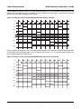
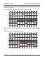
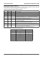
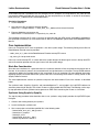
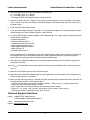
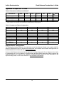
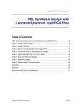
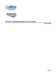
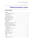
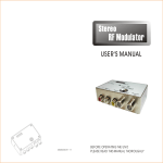
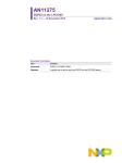
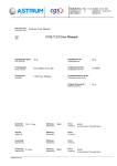
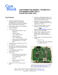
ispLever
CORE
TM
Reed-Solomon Encoder
User’s Guide
October 2005
ipug05_03.0
Lattice Semiconductor
Reed-Solomon Encoder User’s Guide
Introduction
Lattice’s Reed-Solomon Encoder core provides an ideal solution that meets the needs of today’s Reed-Solomon
applications. The Reed-Solomon Encoder core provides a customizable solution allowing forward error correction
in many design applications. This core allows designers to focus on the application rather than the Reed-Solomon
Encoder, resulting in faster time to market.
Reed-Solomon codes are widely used in various applications for forward error correction and detection. Lattice’s
Reed-Solomon Encoder core is a fully synchronous core developed in conjunction with Lattice’s Reed-Solomon
Decoder core to provide a complimentary pair. For more information on Lattice products, refer to the Lattice web
site at www.latticesemi.com.
This user’s guide illustrates the functionality and implementation of the Reed-Solomon Encoder to provide encoding on any data transmission. It also describes a method for achieving the maximum level of performance.
The Reed-Solomon Encoder Core
This section describes the functionality of the Reed-Solomon Encoder core. It includes information on how to customize the Reed-Solomon Encoder core as well as the details necessary to design an application that will interface
with the Reed-Solomon Encoder core. Figure 1 illustrates the functional modules and internal bus structure used in
the Reed-Solomon Encoder core.
Figure 1. Reed-Solomon Encoder Core Block Diagram
Multiplier Array
Control Bus
d_in
rstn
enable
byp
start
clk
Adder Array
Remainder Array
d_out
Control
status
dvalid
rdy
Multiplier Array
The Multiplier Array does the Galois field multiplication between the generator coefficients and the addition of input
data and feedback (modulo 2). This multiplication is an optimized multiplication between the generator coefficients,
which are constants, and the input of the Multiplier Array. This optimization is done when processing the core.
Adder Array
The Adder Array performs addition (modulo 2) on the data from the previous element of the Remainder Array and
the result of the corresponding Galois field multiplication from the Multiplier Array. The outputs from the Adder Array
are latched into the Remainder Array on each clock cycle.
2
Lattice Semiconductor
Reed-Solomon Encoder User’s Guide
Remainder Array
The Remainder Array is a shift register array. It stores the remainder polynomial after the polynomial division. The
remainder polynomial becomes the check symbols once all information symbols have been processed. The
Remainder Array shifts in the data from the Adder Array until no information symbols remain. When all the information symbols have been received, the polynomial multiplication stops and the contents of the Remainder Array are
output to d_out.
Control Block
The control block generates all control signals and determines the state of the Reed-Solomon Encoder. The inputs
control the state of the encoder. The control signals from the control block are sent through the control bus to determine when data should be transmitted to the encoder.
Timing Diagrams
The illustrated timing examples utilize a non-continuous RS (7,3) code. The timing remains the same whether the
core is continuous or non-continuous. However, when the core is continuous, the rdy and dvalid signals are not
used.
Figure 2 illustrates the timing of an RS (7,3) single pipelined encoder during normal operation. The handshake signals status, rdy, and dvalid display how the encoder communicates with the source and destination devices.
Figure 2. Timing of an RS (7,3) Single Pipelined Encoder
clk
rstn
start
enable
byp
d_in
d_out
D6
D5
D4
X3
X2
X1
X0
DN6
DN5
DN4
D6
D5
D4
C3
C2
C1
C0
DN6
status
rdy
dvalid
3
Lattice Semiconductor
Reed-Solomon Encoder User’s Guide
Figure 3 shows the timing of an RS (7,3) single pipelined encoder with byp asserted during the operation of the
encoder. The handshaking signals are identical to normal operation, but the output is shifted due to the extra
bypass data, which does not require check symbols.
Figure 3. Timing of an RS (7,3) Single Pipelined Encoder with byp Asserted
clk
rstn
start
enable
byp
d_in
D6
D5
d_out
D4
DBP
D6
D5
D4
DBP
C3
C2
DN6
DN5
C1
C0
status
rdy
dvalid
Figure 4 explains the timing of an RS (7,3) single pipelined encoder with enable de-asserted during the operation
of the encoder. The handshaking signal, dvalid, indicates the data on d_out is invalid while the encoder maintains its state during the time enable is low.
Figure 4. Timing of an RS (7,3) Single Pipelined Encoder with enable De-asserted
clk
rstn
start
enable
byp
d_in
d_out
D6
D5
D4
XX
X3
X2
X1
X0
DN6
DN5
D6
D5
D4
D4
C3
C2
C1
C0
status
rdy
dvalid
4
Lattice Semiconductor
Reed-Solomon Encoder User’s Guide
Figure 5 explains the timing of an RS (7,3) single pipelined encoder with start re-asserted during the operation of
the encoder. The handshaking signal, rdy, indicates the encoder is ready to receive a new set of data when start is
re-asserted during encoding.
Figure 5. Timing of an RS (7,3) Single Pipelined Encoder with start Re-asserted
clk
rstn
start
enable
byp
d_in
D6
D5
d_out
D4
X3
D6
D5
D4
X3
X2
X1
D6
D5
D4
C3
D6
D5
D4
C3
status
rdy
dvalid
Figure 6 illustrates the timing of an RS (7,3) double-pipelined encoder during normal operation. The handshake
signals, status, rdy, and dvalid, display how the encoder communicates with the source and destination
devices.
Figure 6. Timing of an RS (7,3) Double Pipelined Encoder
clk
rstn
start
enable
byp
d_in
d_out
D6
D5
D4
X3
X2
X1
X0
DN6
DN5
DN4
D6
D5
D4
C3
C2
C1
C0
status
rdy
dvalid
5
Lattice Semiconductor
Reed-Solomon Encoder User’s Guide
Figure 7 shows the timing of an RS (7,3) double-pipelined encoder with byp asserted during the operation of the
encoder. The handshaking signals are identical to normal operation, but the output is shifted due to the extra
bypass data, which does not require check symbols.
Figure 7. Timing of an RS (7,3) Double Pipelined Encoder with byp Asserted
clk
rstn
start
enable
byp
d_in
D6
D5
D4
d_out
DBP
X3
X2
X1
X0
DN6
DN5
D6
D5
D4
DBP
C3
C2
C1
status
rdy
dvalid
Figure 8 explains the timing of an RS (7,3) double-pipelined encoder with enable de-asserted during the operation of the encoder. The handshaking signal, dvalid, indicates the data on d_out is invalid while the encoder
maintains its state during the time enable is low.
Figure 8. Timing of an RS (7,3) Double Pipelined Encoder with enable De-asserted
clk
rstn
start
enable
byp
d_in
d_out
D6
D5
D4
XX
X3
X2
X1
X0
DN6
DN5
D6
D5
D4
D4
C3
C2
C1
status
rdy
dvalid
6
Lattice Semiconductor
Reed-Solomon Encoder User’s Guide
Figure 9 explains the timing of an RS (7,3) double-pipelined encoder with start re-asserted during the operation
of the encoder. The handshaking signal, rdy, indicates the encoder is ready to receive a new set of data when
start is re-asserted during encoding.
Figure 9. Timing of an RS (7,3) Double Pipelined Encoder with start Re-asserted
clk
rstn
start
enable
byp
D6
d_in
D5
D4
d_out
X3
D6
D5
D4
X3
X2
X1
D6
D5
D4
C3
D6
D5
D4
status
rdy
dvalid
Signal Definitions
Table 1 shows the input and output signals for the Reed-Solomon Encoder core. Refer to the ispLEVER™ Software
User’s Manual for additional information.
Table 1. Reed-Solomon Encoder Signals
Signal Name
d_in[s-1:0]
I/O Type
Active
State
Input
N/A
Input data
Signal Description
rstn
Input
Low
Asynchronous reset input
enable
Input
High
Enables the encoder to process data on d_in. When low, the input data is
ignored and d_out holds its state.
byp
Input
High
Indicates the data on d_in should pass directly through to d_out after the
latency. This signal is ignored if enable is low.
start
Input
High
Indicates that the data on d_in is the first information symbol of a new codeword.This signal is ignored if byp is high or enable is low.
clk
Input
Rising Edge Master clock input
d_out[s-1:0]
Output
N/A
Output data
status
Output
High
Indicates the information symbols are present on d_out or byp is asserted.
dvalid
Output
High
Indicates valid data on d_out.Not available with continuous configuration
rdy
Output
High
Indicates the encoder is ready to receive data.Active when rstn is asserted or
when ready to receive data or start is asserted. Inactive when sufficient data
has been received and check symbols are being calculated. Not available with
continuous configuration
7
Lattice Semiconductor
Reed-Solomon Encoder User’s Guide
Reed-Solomon Encoder Parameters
The Reed-Solomon Encoder has several parameters that allow the core to be configured in different modes listed
in Table 2. Table 3 lists the default field polynomial for a given symbol width.
Table 2. Reed-Solomon Encoder Parameter Descriptions
Value
Default
n
Name
3 - 4095
255
Description
k
1 - 4093
239
s
3 - 12
8
f
11 - 8191
rootspace
1 - 65535
1
Root spacing of the generator polynomial. The value of rootspace must satisfy the
following equation: GCD(rootspace, 2S-1) = 1. GCD is Greatest Common Divisor.
gstart
0 - 65535
0
Offset value of the generator polynomial. The starting value for the first root of the
generator polynomial is calculated as rootspace * gstart.
inreg
0, 1
1
0 = the inputs will not be registered
1 = the inputs will be registered
latency
2, 3
3
2 = the input on d_in will take 2 clock cycles to reach d_out
3 = the input on d_in will take 3 clock cycles to reach d_out
algorithm
0, 1
1
Selects between two different multiplication algorithms. Used to improve timing
results
handshake
0, 1
0
1 = the core will be a non-continuous core configuration
0 = the core will be a continuous core configuration
(rdy and dvalid will be used in non-continuous configuration only)
Number of symbols.
Number of information symbols.
Symbol width.
See Table 3 Decimal value of the field polynomial.
Table 3. Reed-Solomon Encoder Default Field Polynomial
Symbol Width
Default Field Polynomial
Decimal Value
3
x3 + x + 1
11
4
4
x +x+1
19
5
x5 + x2 +1
37
6
x6 + x + 1
67
7
x7 + x3 + 1
137
8
x8 + x4 + x3 + x2 + 1
285
9
x9 + x4 + 1
529
10
3
10
x +x +1
1033
11
x11 + x2 + 1
2053
12
12
6
4
x +x +x +x+1
8
4179
Lattice Semiconductor
Reed-Solomon Encoder User’s Guide
Reed-Solomon Encoder Core Design Flow
The Reed-Solomon IP Core can be implemented using various methods. The scope of this document covers only
the push-button Graphical User Interface (GUI) flow. Figure 10 illustrates the software flow model used when
designing with the Reed-Solomon Encoder core.
Figure 10. Lattice IP Core Implementation Flow
Start
Install and launch ispLEVER software
Obtain desired IP package (download
Core Evaluation package or purchase
IP package)
Protected
Simulation
Model
Install IP package
IP Core Netlist
Perform functional simulation with
the provided core model
Synthesize top-level design with the
IP black box declaration
Place and route the design
Run static timing analysis
Done
IPexpress™
The Lattice IP configuration tool, IPexpress, is incorporated in the ispLEVER® software. IPexpress includes a GUI
for entering the required parameters to configure the core. For more information on using IPexpress and the
ispLEVER design software, refer to the software help and tutorials included with ispLEVER. For more information
on ispLEVER, see the Lattice web site at www.latticesemi.com/software.
Functional RTL Simulation Under ModelSim (PC Platform)
Note: The following procedures are shown using the ORCA® Series 4 version of the Reed-Solomon Decoder
core. For other device versions, refer to the Readme release notes included in that evaluation package.
Once the Reed-Solomon Encoder core has been downloaded and unzipped to the designated directory, the core is
ready for evaluation. The functional simulation of the RS Encoder core involved developing a verification environment that supports a very comprehensive test suite.
9
Lattice Semiconductor
Reed-Solomon Encoder User’s Guide
A simulation script file is provided in the “eval” directory for RTL simulation. The script file eval_sim_rsenc.do uses
pre-compiled models provided with this package. The pre-compiled library of models is located in the directory
reeds_enco_o4_1_00x/orca4/ver1.3/lib/modelsim/work.
Simulation Procedures:
1. Launch ModelSim
2. Using the main GUI, change the directory location:
Select: File -> Change Directory -> reeds_enco_o4_1_00x/orca4/ver1.3/eval/simulation
3. Execute <Modelsim macro name>.do
Select: Macro -> Execute Macro -> scripts/eval_sim_rsenc.do
The functional simulation for IP cores is currently not applicable with the OEM version of ModelSim embedded in
the ispLEVER 3.0 software. For more information on how to use ModelSim, please refer to the ModelSim User’s
Manual.
Core Implementation
Users can instantiate the IP core to implement it into their system design. The following Verilog source files for
Reed-Solomon Encoder core are provided:
• reeds_enco_o4_1_00x.v for the Reed-Solomon Encoder core-top RTL source
• top_rsenc_pll.v for top-level source
Users can use the core-top RTL as a black box to the system designs. All default signal names in the top-level RTL
source file must be replaced with real signal names from the system design.
Black Box Consideration
Since the core is delivered as a gate-level netlist, the synthesis software will not re-synthesize the internal nets of
the core. In the synthesis process, the instantiated core must be declared as a black box. The ispLEVER software
automatically detects the provided netlist of the instantiated IP core in the design. For more detailed information
regarding Synplify’s black box declaration, please refer to the Instantiating Black Boxes in Verilog section of the
Synplify reference manual.
The core implementation consists of synthesis and place and route sections. Each of the sections is described
below.
Two synthesis tools, Synplicity® Synplify® and LeonardoSpectrum™, are included in the ispLEVER software for
seamless processing of designs. The current IP cores are being tested with EDIF flow. The following are the stepby-step procedure for each synthesis tool to generate an EDIF netlist containing the IP core as a black box.
Synthesis Using Synplicity Synplify
The step-by-step procedure below describes how to run synthesis using Synplify outside the ispLEVER Project
Navigator.
1. Create a new working directory for synthesis.
2. Launch the Synplify synthesis tool.
3. Start a new project and add the specified files in the following order:
~/source/reeds_enco_o4_1_00x_params.v
~/source/orca4_synplify.v
~/source/pll_orca.v
~/source/reeds_enco_o4_1_00x.v
~/source/<top-level RTL source>.v
10
Lattice Semiconductor
Reed-Solomon Encoder User’s Guide
Note: <top-level RTL source> could be the user’s top-level design or the top-level source (top_rsenc_pll.v) file
in the source directory of the downloaded package.
4. In the Implementation Options, select a target device 4E02, speed grade -2 and package BA352.
5. Specify an EDIF netlist filename and EDIF netlist output location in the Implementation Options. This top-level
EDIF netlist will be used during place and route.
6. Be sure the IP core (reeds_enco_o4_1_00x) is instantiated inside top-level RTL source file.
7. In the Implementation Options, set the following:
• Fanout guide: 500
• Enable FSM compiler
• Enable resource sharing
• Set the global frequency constraint to 195MHz.
8. Select Run.
Synthesis Using LeonardoSpectrum
The step-by-step procedure provided below describes how to run synthesis using LeondardoSpectrum outside the
ispLEVER Project Navigator.
1. Create a new working directory for synthesis.
2. Launch the LeonardoSpectrum synthesis tool.
3. Start a new project and select Lattice device technology ORCA-4E.
4. Set the source directory as the working directory.
5. Open the specified files in the following order:
~/source/reeds_enco_o4_1_00x_params.v
~/source/<top-level RTL source>.v
~/source/pll_orca.v
~/source/reeds_enco_o4_1_00x.v
Note: <top-level RTL source> could be users’ top-level design or the top-level source (top_rsenc_pll.v) file in
the source directory of the downloaded package.
6. Set the synthesis directory, created in step 1, as the path where you would like to save the output netlist.
7. Specify an EDIF netlist filename for the output file. This top-level EDIF netlist will be used during place and
route.
8. Be sure the IP core (reeds_enco_o4_1_00x) is instantiated inside top-level RTL source file.
9. Select Run Flow.
Place and Route
Once the EDIF netlist is generated, the next step is to import the EDIF into the Project Navigator. The step-by-step
procedure provided below describes how to perform place and route in ispLEVER for an ORCA® device:
1. Create a new working directory for place and route.
2. Start a new project, assign a project name and select the project type as EDIF.
3. Select an ORCA target device, with -2 speed grade and BA352 package.
11
Lattice Semiconductor
Reed-Solomon Encoder User’s Guide
4. Copy the following files to the place and route working directory:
a) ..\..\par\reeds_enco_o4_1_00x.ngo
b) ..\..\par\reeds_enco_o4_1_00x.prf
c) The top-level EDIF netlist generated from running synthesis
5. Rename the reeds_enco_o4_1_00x.prf file (in step 4) to match the project name. For example, if the project
name is “demo”, then the .prf file must be renamed to demo.prf. The preference file name must match that of
the project name.
6. Import the EDIF netlist into the project.
7. In the ispLEVER Project Navigator, select Tools->Timing Checkpoint Options. The Timing Checkpoint Options
window will pop-up. In both Checkpoint Options, select Continue.
8. In the ispLEVER Project Navigator, highlight Place & Route Design, with a right mouse click select Properties.
Set the following Properties:
• Placement Iterations: 1
• Placement Save Best Run: 1
• Placement Iteration Start Point: 20
• Routing Resource Optimization: 5
• Routing Delay Reduction Passes: 2
• Routing Passes: 15
• Placement Effort Level: 5
All other options remain at their default values. The properties shown above are the settings for OC192 mode.
Each configuration has its own properties settings. For the appropriate settings for specific configuration,
please refer to the readme.htm that located in the downloaded package.
9. Select the Place & Route Trace Report in the Project Navigator to execute Place and Route and generate a
timing report for ORCA.
10. If the fMAX for the core does not meet the required static timing, then proceed to step 11. Otherwise, jump to
step 13.
11. Select the Cycle Stealing process in the Project Navigator.
12. Select the Place & Route Trace Report process again to generate a new timing report. The Timing Summary
section should indicate no timing errors.
13. When you open the timing report, it is possible you might see some timing violations due to over-constraint. Do
the following steps to obtain a correct timing report:
• Copy the file post_route_trace.prf that is located in directory ~/reeds_enco_o4_1_00x/orca4/ver1.0/par
to the place and route working directory in step 1.
• Open a DOS-shell and change its directory to the working directory in step 1.
• Type: trce -v 1 -c -o post_route_trace.twr <your project_name>.ncd post_route_trace.prf
• The new timing report is generated in post_route_trace.twr
Technical Support Assistance
Hotline: 1-800-LATTICE (North America)
+1-503-268-8001 (Outside North America)
e-mail: [email protected]
Internet: www.latticesemi.com
12
Lattice Semiconductor
Reed-Solomon Encoder User’s Guide
Appendix for ORCA® Series 4 FPGAs
Table 4. Performance and Utilization1
Parameter File
ORCA 4
PFUs
Mode
LUTs
Registers
I/Os
sysMEM™
EBRs
fMAX (MHz)
reeds_enco_o4_1_001.lpc
OC192
58
210
194
24
N/A
168
reeds_enco_o4_1_002.lpc
CCSDS
88
327
323
24
N/A
156
reeds_enco_o4_1_003.lpc
DVB
58
201
194
24
N/A
167
reeds_enco_o4_1_004.lpc
ATSC
71
233
226
24
N/A
166
1. Performance and utilization characteristics for OR4E02-2BA352. When using other devices, performance may vary.
Table 5. Parameters for Typical Configurations
Name
CCSDS
DVB
ATSC
OC192
n
255
204
207
255
k
223
188
187
239
s
8
8
8
8
f
391
285
285
285
rootspace
11
1
1
1
gstart
112
0
0
0
inreg
1
1
1
1
latency
3
3
3
3
algorithm
1
1
1
1
handshake
0
0
0
0
Supplied Netlist Configurations
The Ordering Part Number (OPN) for all configurations of the Reed-Solomon Encoder core targeting ORCA Series
4 devices is REEDS-ENCO-O4-N1. Table 4 lists the netlists that are available in the Evaluation Package, which can
be downloaded from the Lattice web site at www.latticesemi.com.
You can use the IPexpress software tool to help generate new configurations of this IP core. IPexpress is the Lattice
IP configuration utility, and is included as a standard feature of the ispLEVER design tools. Details regarding the
usage of IPexpress can be found in the IPexpress and ispLEVER help system. For more information on the
ispLEVER design tools, visit the Lattice web site at: www.latticesemi.com/software.
13
Lattice Semiconductor
Reed-Solomon Encoder User’s Guide
Appendix for ispXPGA® FPGAs
Table 6. Performance and Resource Utilization1
Parameter File
Mode
ispXPGA
PFUs
LUTs
Registers
I/Os
sysMEM
EBRs
fMAX (MHz)
reeds_enco_xp_1_001.lpc
OC192
86
273
248
24
N/A
166
reeds_enco_xp_1_002.lpc
CCSDS
161
504
457
24
N/A
149
reeds_enco_xp_1_003.lpc
DVB
84
273
240
24
N/A
155
reeds_enco_xp_1_004.lpc
ATSC
130
417
307
24
N/A
157
1. Performance and utilization characteristics are generated using LFX125B-04F256C in Lattice ispLEVER ® v.3.x software. The evaluation
version of this IP core only works on this specific device density, package, and speed grade.
Table 7. Parameters for Typical Configurations
Name
CCSDS
DVB
ATSC
OC192
n
225
204
207
255
k
223
188
187
239
s
8
8
8
8
f
391
285
285
285
rootspace
11
1
1
1
gstart
112
0
0
0
inreg
1
1
1
1
latency
3
3
3
3
algorithm
1
1
1
1
handshake
0
0
0
0
Supplied Netlist Configurations
The Ordering Part Number (OPN) for all configurations of the Reed-Solomon Encoder core targeting ispXPGA
devices is REEDS-ENCO-XP-N1. Table 6 lists the netlists that are available in the Evaluation Package, which can
be downloaded from the Lattice web site at www.latticesemi.com.
You can use the IPexpress software tool to help generate new configurations of this IP core. IPexpress is the Lattice
IP configuration utility, and is included as a standard feature of the ispLEVER design tools. Details regarding the
usage of IPexpress can be found in the IPexpress and ispLEVER help system. For more information on the
ispLEVER design tools, visit the Lattice web site at: www.latticesemi.com/software.
14
Lattice Semiconductor
Reed-Solomon Encoder User’s Guide
Appendix for LatticeECP™ and LatticeEC™ FPGAs
Table 8. Performance and Resource Utilization1
Parameter File
Mode
SLICEs
LUTs
Registers
I/Os
sysMEM
EBRs
fMAX
(MHz)
reeds_enco_e2_1_001.lpc
OC192
147
252
217
24
N/A
206
reeds_enco_e2_1_002.lpc
CCSDS
280
460
413
24
N/A
194
reeds_enco_e2_1_003.lpc
DVB
149
253
220
24
N/A
205
reeds_enco_e2_1_004.lpc
ATSC
196
320
279
24
N/A
201
1. Performance and utilization characteristics are generated using LFEC20E-5F672C in Lattice’s ispLEVER v.4.1 software. When using this IP
core in a different device, density, package, or speed grade, performance may vary.
Table 9. Parameters for Typical Configurations
Name
CCSDS
DVB
ATSC
OC192
n
255
204
207
255
k
223
188
187
239
s
8
8
8
8
f
391
285
285
285
rootspace
11
1
1
1
gstart
112
0
0
0
inreg
1
1
1
1
latency
3
3
3
3
algorithm
1
1
1
1
handshake
0
0
0
0
Supplied Netlist Configurations
The Ordering Part Number (OPN) for all configurations of the Reed-Solomon Encoder core targeting LatticeECP/EC
devices is REEDS-ENCO-E2-N1. Table 8 lists the netlists that are available in the Evaluation Package, which can be
downloaded from the Lattice web site at www.latticesemi.com.
You can use the IPexpress software tool to help generate new configurations of this IP core. IPexpress is the Lattice
IP configuration utility, and is included as a standard feature of the ispLEVER design tools. Details regarding the
usage of IPexpress can be found in the IPexpress and ispLEVER help system. For more information on the
ispLEVER design tools, visit the Lattice web site at: www.latticesemi.com/software.
15