1
LucidControl AI4, User Manual
2013-02-20
User Manual
LucidControl AI4
4 Channel Analog Input USB Module
Page 1 of 19
LucidControl AI4, User Manual
2013-02-20
1 Introduction
This document describes the functionality of the LucidControl AI4 USB module measuring
4 analog voltages controllable via Universal Serial Bus.
A basic description of the complete LucidControl product family can be found in the
document LucidControl User Manual.
This document concentrates on the specific topics of the analog input module which is
described here with all its details. In order to set up the module in a fast way please see the
LucidControl AI4 One Sheet Manual
which provides all information necessary to start working with the module out of the box
without reading lots of documentation.
2 Hardware
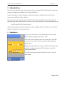
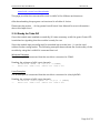
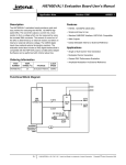
Fig. 1 shows the sketch of the Analog Input AI4 module
with 4 analog voltage inputs (AI0 ~ AI3).
All LucidControl modules have two connectors, one USB
connector and an IO- Connector which makes it easy to
setup them.
While the upper USB connector is used for interconnection
with the computer, the lower IO-Connector is used for
inputs and outputs.
The IO Connector provides 8 terminals in total - two for
each input.
Fig. 1 Analog Input Module
Page 2 of 19
LucidControl AI4, User Manual
2013-02-20
2.1 Configurations
Module Type
Positive Inputs
Symmetrical
Inputs
Type Number
LCTR-AI4-5
LCTR-AI4-10
LCTR-AI4-24
LCTR-AI4-5S
LCTR-AI4-10S
LCTR-AI4-24S
Input Voltage Range
VMin
VMax
0V
5V
0V
10 V
0V
24 V
-5 V
5V
-10 V
10 V
-24 V
24 V
Tab. 1 Input Voltage Range
Tab. 1 shows the available module types with their input voltage range.
The analog input module can measure voltages in the range VMin ≤ VIN ≤ VMax.
2.2 Interface and Interconnection
2.2.1 USB Connection
LucidControl USB modules are connected to the computer by using a standard USB cable
which must not extend a length of 5 m. They are “bus powered” which means that the host
computer supplies the module with power.
LucidControl AI4 module is rated with a maximum current of 40 mA.
Note:
Supplying USB devices with power is not critical using a desktop computer or notebooks
but it must be considered that the total power of one USB port is limited to 500 mA.
Note:
The USB ports of the Raspberry Pi® are limited to 100 mA. This means that maximum two
devices can be connected to a port directly.
Note:
Using an active USB-Hub with its own power supply allows the connection of additional
devices in the case that the host is not able to supply them.
Page 3 of 19
LucidControl AI4, User Manual
2013-02-20
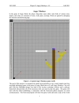
2.2.2 IO Connection
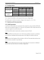
Fig. 2 shows the interconnection of the module in a typical
application.
The analog input voltages are represented by voltage sources
with a voltage within the valid range.
The terminals 2, 4, 6 and 8 are internally connected to ground.
Fig. 2 Analog Input Module
Connection
All applied signals must be in the supported range. Under no circumstances the
applied signals must exceed +30 V resp. -30 V.
Page 4 of 19
LucidControl AI4, User Manual
2013-02-20
2.3 Setup of Hard- and Software
Setting up LucidControl hardware is extremely easy:
1 Ensure that no signal is applied to the IO Connector
2 Connect LucidControl via USB with the computer
3 Applies for Microsoft windows only: The system asks for an installation file. This is
not a driver but only an information file (INF). The file can be downloaded from our
website www.lucid-control.com/downloads
4 That’s all. LucidControl switches the green power LED on and the module is ready
for usage.
2.3.1 Windows
As mentioned the installation under Microsoft Windows requires the information file.
After finished installation the Windows Device Manager contains a new serial port (COM).
The module can be accessed using this port.
Note:
Even if more than one module is connected to a computer Windows ensures that the same
serial port number is assigned to the module(s) after restart.
2.3.2 Linux
Despite to Windows installation under Linux the module is usable immediately after
connection without any additional steps. Linux installs /dev/ttyACM devices for any
module connected to the computer.
Note:
By default Linux cannot ensure that the same /dev/ttyACM device is assigned to the same
module on restart. But as long as only one module is connected to the computer it is
ensured that it is accessible via /dev/ttyACM0.
This problem can be solved by the LucidIoCtrl command line tool which can create static
devices always pointing to a specific module. Moreover the device can be given useful
names e.g. dev/digitalIoKitchen.
Please see the section … of the general LucidIo User Manual for more information.
2.3.3 Get command line LucidIoCtrl
LucidIoCtrl command line tool can be downloaded from our website:
Page 5 of 19
LucidControl AI4, User Manual
2013-02-20
www.lucid-control.com/downloads
This page provides the command line tool LucidIoCtrl for different architectures.
After downloading the program can be stored in a folder of choice.
Please see the section … of the general LucidControl User Manual for more information
about this helpful tool.
2.3.4 Ready for Take-Off
Once the module was installed successfully (if it was necessary at all) the green Power LED
is switched on signaling that the module is ready for use.
Since the module was preconfigured for standard input mode (see ...) it can be used
without further configuration. The following examples demonstrate the functionality of the
module by using the LucidIoCtrl command line tool.
Windows Examples
For all examples it is assumed that the module is connected to COM1.
Reading the voltages of all 4 input channels
->
LucidIoCtrl –dCOM1 –tV –c0,1,2,3 –r [ENTER]
CH00:5.000 CH01:5.000 CH02:5.000 CH03:5.000
Linux Examples:
For all examples it is assumed that the module is connected to /dev/ttyACM0.
Reading the voltages of all 4 input channels
->
LucidIoCtrl –d/dev/ttyACM0 –tV –c0,1,2,3 –r [ENTER]
CH00:5.000 CH01:5.000 CH02:5.000 CH03:5.000
Page 6 of 19
LucidControl AI4, User Manual
2013-02-20
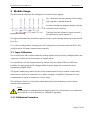
3 Module Usage
The AI4 module measures the voltages of connected input signals.
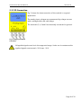
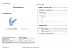
Fig. 3 illustrates the processing of the analog
input signals in Standard Mode.
In order to keep the diagram simple it shows
only two active channels.
Fig. 3 Input Processing
The blue lines are related to input channel 1,
the red lines to input channel 2.
The figure illustrates the periodical capture of both input channels within the scan interval
time TScan.
TScan can be configured by changing the IO Configuration Parameter inAnScanTime. This
could be done for faster measurement intervals.
3.1 Input Calibration
The LucidControl AI4 module measures analog signals (more precisely voltages) which are
captured, conditioned and converted to digital values.
In contradiction to logic signals where by nature only two states LOW and HIGH are
possible for analog signals all voltages within a given range are converted to their
representing digital value.
The signal conditioning which is part of the measurement circuit contains components
which are not free from tolerances (e.g. offset voltages of amplifier). These have to be
compensated in order to measure a correct value.
The calibration function of the AI4 module described in the following corrects these
measurement tolerances.
Note:
All modules are calibrated before shipping and it is not necessary to recalibrate a
new module nor is it necessary to calibrate it regularly!
3.1.1 Calibration Procedure
Page 7 of 19
LucidControl AI4, User Manual
2013-02-20
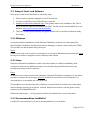
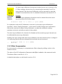
For short input calibration the inputs must be shortcut as it is shown in Fig.
4. After creating a shortcut e.g. by connecting the terminals 1 and 2 for
input channel 0 the short input calibration can be executed by using the
LucidIoCtrl command line tool. For detailed information see section 3.2.3.
Fig. 4 Analog
Input Sort
Calibration
Example
The short input calibration should be done for channel 0 and the result
should be stored for further usage.
LucidIoCtrl –dCOM1 –c0 –a --short –p –-quiet [ENTER]
In combination with the I/O Calibration command (-a) the short input calibration is
specified (--short). Passing Parameter --quiet causes LucidIoCtrl skips user confirmation
before the command is started. Using Parameter –p makes the calibration setting
persistent so that is used after a restart of the module.
The short input calibration for channel 0 is finished and the remaining input channels can
be calibrated the same way afterwards.
Reading the input voltage after short input calibration was done should return a voltage of
0 V (assuming that the shortcut between the terminals was not removed)
->
LucidIoCtrl –dCOM1 –c0 –tV –r [ENTER]
CH0:0.000
3.1.2 Offset Compensation
In some cases it is necessary to compensate an offset voltage by adding a value to the
measured result.
The value of the IO Configuration Parameter inAnOffset is added to the measured result.
This allows offset correction of ± 3 V.
A detailed description can be found in section 3.3.4.
Page 8 of 19
LucidControl AI4, User Manual
2013-02-20
3.2 Commands
After an input was set up correctly and configured it is possible to read the input value by
using the commands GetIo for a single value or GetIoGroup in order to read a group of
input values of the same type.
Accessing inputs and outputs is a very common task which is mostly identical for all Lucid
Control modules. Please refer to the section 3.2.1.1, 3.2.1.2 and 4.3 of the general
LucidControl manual for comprehensive information covering reading and writing of
inputs and outputs in general.
The following sections describe in detail the commands which are supported by the AI4
module.
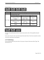
3.2.1 GetIo
This command reads a value from an input.
Command
Opcode
GetIo
0x46
Access
Call (-tV)
Return
LucidIoCtrl –d[COMx] –c[Channel] –tV –r
CHn:dd
Call (-tA)
Return
LucidIoCtrl –d[COMx] –c[Channel] –tA –r
CHn:dd
Read
LucidIoControl Command Line Tool
n
vv
n
dd
Input Channel
Input Voltage
Input Channel
ADC Value Voltage
Note
When using the LucidIoCtrl command line tool the distinction between GetIo and
GetIoGroup commands is not necessary since the program handles this automatically.
LucidIoCtrl Command Line Tool Example
Read voltage from input channel 0:
->
LucidIoCtrl –dCOM4 –c0 –tV -r [ENTER]
CH00:5.000
Read digital ADC value from input channel 0:
->
LucidIoCtrl –dCOM4 –c0 –tA -r [ENTER]
CH00:0x0064 (100)
Page 9 of 19
LucidControl AI4, User Manual
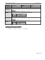
Request Frame
OPC
P1
0x46
Channel
2013-02-20
P2
Value Type
LEN
0
Value
Channel
Description
Number of input or output channel (Range: 0 ~ 3)
Supported Value Types
Value Type
Value Range
Signed Voltage
-100,000,000 µV ~
Resolution 1 µV
100,000,000 µV
(0x1D)
(-100 V ~ 100 V)
Value Type
Signed Voltage
-30,000 mV ~
Resolution 1 mV
30,000 mV
(0x0C)
(-30 V ~ 30 V)
ADC Value
0 ~ 65,535
(0x10)
Size
4 Bytes
2 Bytes
2 Bytes
Fig. 5 GetIo Request
Response Frame:
Status
LEN
Status
Length
Data Field
Value(s)
In case of successful execution the command returns the value of the specified channel
number.
In the case of an error the command returns Execution Status Code documented in section
4.4 of the LucidControl User Manual.
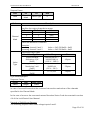
3.2.2 GetIoGroup
This command reads the input values of a group of inputs of the same Value Type. See
also section 3.2.1.
Page 10 of 19
LucidControl AI4, User Manual
2013-02-20
Command
Opcode
GetIoGroup
Access
Read
0x48
LucidIoControl Command Line Tool
Call (-tV)
LucidIoCtrl –d[COMx] –c[Channels] –tV –r
Return
Channels:
Comma separated list of channels e.g. –c0,1,3
List of values sorted from lower to higher channels
CHn:vv
n
vv
Call (-tA)
Input Channel
Input Voltage
LucidIoCtrl –d[COMx] –c[Channels] –tA –r
Channels:
Comma separated list of channels e.g. –c0,1,3
Return
CHn:dd
n
dd
Input Channel
ADC Value
LucidIoCtrl Command Line Tool Example
Read voltages from all input channels:
->
LucidIoCtrl –dCOM4 –c0,1,2,3 –tV –r [ENTER]
CH0:6.000 CH1:2.500 CH2:0.000 CH3:-2.500
Page 11 of 19
LucidControl AI4, User Manual
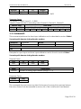
Request Frame
OPC
0x48
P1
Channel
Mask
2013-02-20
P2
LEN
Value Type
0
Value
Channel
Mask
Value
Type
Description
Channel Mask
Specifies the output channels to access
Channel
Bit Position
Value
0
0
0x01
1
1
0x02
2
2
0x04
3
3
0x08
Values are bitwise or combined
Examples:
Accessing channel 0 and 3
Accessing channel 1 and 2
Supported Value Types
Value Type
Signed Voltage
Resolution 1 µV
(0x1D)
Signed Voltage
Resolution 1 mV
(0x0C)
ADC Value
(0x10)
Value = 0x01 OR 0x08 = 0x09
Value = 0x02 OR 0x04 = 0x06
Value Range
-100,000,000 µV ~
100,000,000 µV
(-100 V ~ 100 V)
-30,000 mV ~
30,000 mV
(-30 V ~ 30 V)
0 ~ 65,535
Size
4 Bytes
2 Bytes
2 Bytes
Fig. 6 GetIoGroup Request
Response Frame:
Status
LEN
Status
Length
Data Field
Value
In case of successful execution the command returns the read values of the channels
specified in the Channel Mask.
In the case of an error the command returns Execution Status Code documented in section
4.4 of the LucidControl User Manual.
Example of GetIoGroup Request:
The following request frame reads voltage inputs 0 and 1
Page 12 of 19
LucidControl AI4, User Manual
Opcode
P1
0x48
0x03
Channel Mask (P1):
2013-02-20
P2
0x00
Length
0x00
0x01 OR 0x02 = 0x03
Response Frame:
For input 0 = 5.000 V, input 2 = 2.500V
Values in Data Field are in ascending order Channel 0, Channel 1, Channel3.
Header Field
Data Field
Status
LEN
Value Channel 0
Value Channel 1
0x00
0x08
0x40 0x4B 0x4C 0x00 0xA0 0x25 0x26 0x00
3.2.3 CalibrateIO
This command performs the short input calibration as it is described in section Fehler!
Verweisquelle konnte nicht gefunden werden..
Command
Opcode
CalibrateIo
Access
0x52
LucidIoControl Command Line Tool
Call
LucidIoCtrl –d[COMx] –c[Channel] –a {--quiet} {–p} {--short}
Examples for open input and short input calibration can be found in section Fehler!
Verweisquelle konnte nicht gefunden werden..
Request Frame
OPC
P1
0x52
Channel
Value
Channel
P2
0x00
LEN
0x00
Description
Number of analog input channel (Range: 0 ~ 3)
Response Frame
Status
LEN
Status
0x00
The command does not return any data. In the case of an error the command returns
Execution Status Code documented in section 4.4 of the LucidControl User Manual.
Page 13 of 19
LucidControl AI4, User Manual
2013-02-20
3.3 Parameters
LucidControl modules allow configuration by a set of System Configuration Parameters
and IO Configuration Parameters.
The Parameters are accessible via the SetParam and GetParam command which are
described in sections 4.3.5 and 4.3.6 of the LucidControl User Manual.
3.3.1 inAnValue
This IO Configuration Parameter contains the ADC value of the input.
Parameter
Address
Values
Default Value
Parameter Name
Call (Get)
inAnValue
Access
0x1000
ADC Input Value
0x00
Parameter Type
LucidIoControl Command Line Tool
inAnValue
Parameter Values
Read
2 Bytes unsigned
0x00 or 0x01
LucidIoCtrl –d[COMx] –c[Channel] –ginAnValue
LucidIoCtrl Command Line Tool Example
Read value of input channel 0:
->
LucidIoCtrl –dCOM4 –c0 –ginAnValue [ENTER]
inAnValue=0
Note:
For normal operation it is recommended to use the function GetIo (3.2.1) in order to read
the input value. The parameter provides the ADC Value (Value Type 0x10) only.
Page 14 of 19
LucidControl AI4, User Manual
2013-02-20
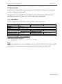
3.3.2 inAnMode
Parameter
Address
Values
Default Value
Parameter Name
Call (Set)
Call (Get)
inAnMode
0x1100
Input Mode
Byte
0x00
0x01
Access
Read / Write
Mode
inactive
standard
0x00
Parameter Type
LucidIoControl Command Line Tool
inAnMode
Parameter Values
1 Byte unsigned
inactive / standard
LucidIoCtrl –d[COMx] –c[Channel] –sinAnMode=[Mode] {-p}
{--default}
LucidIoCtrl –d[COMx] –c[Channel] –ginAnMode
LucidIoCtrl Command Line Tool Example
Set operation mode of input channel 0 to Standard Mode and make the setting persistent.
LucidIoCtrl –dCOM4 –c0 –sinAnMode=standard –p [ENTER]
Read the operation mode of input channel 0
->
LucidIoCtrl –dCOM4 –c0 –ginAnMode [ENTER]
inAnMode=standard
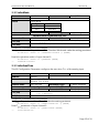
3.3.3 inAnScanTime
This IO Configuration Parameter configures the scan time TScan of the analog input.
Parameter
Address
Values
Default Value
Parameter Name
Call (Set)
Call (Get)
inAnScanTime
Access
0x1111
TScan in ms (milli seconds)
50 ms ≤ TScan ≤ 10 s
200 (200 ms)
Parameter Type
LucidIoControl Command Line Tool
inanScanTime
Parameter Values
Read / Write
2 Bytes unsigned
Time [ms]
LucidIoCtrl –d[COMx] –c[Channel] –sinAnScanTime=[Time]
{-p} {--default}
LucidIoCtrl –d[COMx] –c[Channel] –ginAnScanTime
LucidIoCtrl Command Line Tool Example
Set TScan of input channel 0 to 0.5 s and make the setting persistent.
LucidIoCtrl –dCOM4 –c0 –sinAnScanTime=500 –p [ENTER]
Read TScan parameter of input channel 0
->
LucidIoCtrl –dCOM4 –c0 –ginAnScanTime [ENTER]
inDiScanTime=500
Page 15 of 19
LucidControl AI4, User Manual
2013-02-20
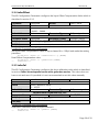
3.3.4 inAnOffset
This IO Configuration Parameter configures the Input Offset Compensation Value which is
described in section 3.1.2.
Parameter
Address
Values
Default Value
Parameter Name
Call (Set)
Call (Get)
inAnOffset
Access
Read / Write
0x1120
Offset Compensation in 100 µV steps (-3 V ~ 3 V)
-30,000 ~ 30000
0
Parameter Type
2 Bytes signed
LucidIoControl Command Line Tool
inAnOffset
Parameter Values
Voltage [100µV]
LucidIoCtrl –d[COMx] –c[Channel] –sinAnOffset=[Voltage]
{-p} {--default}
LucidIoCtrl –d[COMx] –c[Channel] –ginAnOffset
LucidIoCtrl Command Line Tool Example
Set Input Offset Compensation value of input channel 0 to -500µV and make the setting
persistent.
LucidIoCtrl –dCOM4 –c0 –sinAnOffset=-5 –p [ENTER]
Read Offset Compensation value
->
LucidIoCtrl –dCOM4 –c0 –ginAnOffset [ENTER]
inAnOffset=-5
3.3.5 inAnCal
This IO Configuration Parameter configures the short calibration value which is described
in section Fehler! Verweisquelle konnte nicht gefunden werden.. The value does not
have a unit and even if it possible it is not recommended to set this value manually.
Parameter
Address
Values
Default Value
Parameter Name
Call (Set)
Call (Get)
inAnCal
Access
0x1130
Short Calibration Value
0 ~ 65,535
0
Parameter Type
LucidIoControl Command Line Tool
inAnCal
Parameter Values
Read / Write
2 Bytes unsigned
0 ~ 65,535
LucidIoCtrl –d[COMx] –c[Channel] –sinAnCal=[Value]
{-p} {--default}
LucidIoCtrl –d[COMx] –c[Channel] –ginAnCal
LucidIoCtrl Command Line Tool Example
Read Short Calibration Value of input channel 0
->
LucidIoCtrl –dCOM4 –c0 –ginAnCal [ENTER]
inAnCal=760
Page 16 of 19
LucidControl AI4, User Manual
2013-02-20
Page 17 of 19
LucidControl AI4, User Manual
2013-02-20
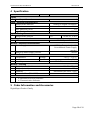
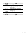
4 Specification
Parameter
Condition
Inputs
No of Input Channels
Input - Electrical Characteristics
Measurement Method
Resolution
Max. Measuring Error
Input Resistance
Input – Timing Characteristic
Measurement Interval
Module – Communication
USB
Module – Electrical Characteristics
Power Supply
Value
4
Analog to Digital Conversion
14 bit
1%
> 100 kΩ
TScan
Maximum Rated Supply Current
Module – Environment
Temperature
Storage
Operation
Humidity
Module – Housing
Dimensions L x W x H
Weight (in total)
Assembly
Protection Class (DIN 40050)
Module - Indicators
Operation and Error Indicator
Communication Indicator
50 ms ≤ t ≤ 10 s
2.0 Full Speed CDC Profil
USB Bus Powered with +5V
No additional Power Supply
needed.
40 mA
-20 °C … +70 °C
0 °C … +55 °C
< 85 % RH, non-condensing
90 x 54 x 62 mm
120 g
Rail-Mount (EN 50022, TS35)
IP20
5 Order Information and Accessories
Digital Input Product Family
Page 18 of 19
LucidControl AI4, User Manual
Order Code
LCTR-AI4-05
LCTR-AI4-10
LCTR-AI4-24
LCTR-AI4-05S
LCTR-AI4-10S
LCTR-AI4-24S
2013-02-20
Product
LucidControl Analog Input USB Module with 4
channels 0 ~ 5 V.
LucidControl Analog Input USB Module with 4
channels 0 ~ 10 V.
LucidControl Analog Input USB Module with 4
channels 0 ~ 24 V.
LucidControl Analog Input USB Module with 4
channels -5 ~ 5 V.
LucidControl Analog Input USB Module with 4
channels -10 ~ 10 V.
LucidControl Analog Input USB Module with 4
channels -24 ~ 24 V.
The following accessories are available:
Order Code
LCTR-AK1710-8
Product
Plug-In Terminal 8-way 1,5 mm² wire
Page 19 of 19