1
COLD PLATE
FEA ANALYSIS
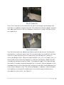
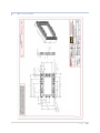
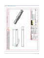
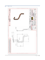
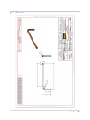
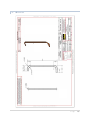
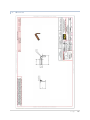
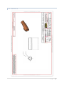
In the ICS, the copper cold plate is the device that exchanges heat from the heat source
to the fluid (refrigerant). The cold plate is mounted directly to the heat source. Thermal
grease is applied between the cold plate and heat source to reduce the contact thermal
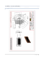
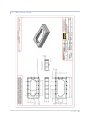
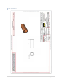
resistance. A custom cold plate was designed by the team for the ICS.
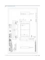
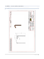
The first characteristic of the cold plate that was determined was the overall size. In
the current Cool Cube, the cold plate is large enough to remove the necessary amount
of heat from the source, but it is not large enough adequately display the phase-change
of the refrigerant. Therefore, the team decided to design a larger cold plate to use on
the ICS. The overall dimensions were selected to be 0.18 m (7 in.) by 0.09 m (3.5 in.).
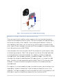
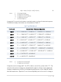
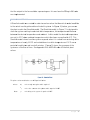
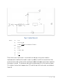
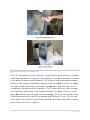
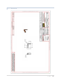
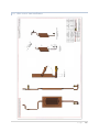
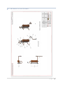
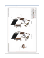
After the overall dimensions were selected, the flow cavity was designed. The flow
cavity consists of an inlet and outlet orifice, flow distributers, and micro-channels. The
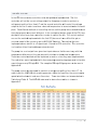
purpose of the flow distributers is to equally distribute the refrigerant to the microchannels so that the flow through the channels is uniform. The flow distributers were
optimized for uniform flow by using a trial and error method. The model was adjusted
using SolidWorks software until a uniform flow through the channels was
accomplished. The analysis was performed using the FEA simulation tools included in
SolidWorks.
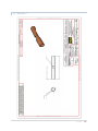
After the flow distributors were designed, the channel layout was designed. Since the
channels needed to be large enough to easily view the flow of the refrigerant and the
evaporation, it was determined that the cold plate should contain no more than 30
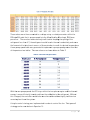
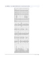
channels. Three different channel layouts were compared using FEA. The first layout
contained 10 channels, the second contained 20 channels, and the third contained 30
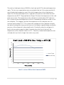
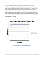
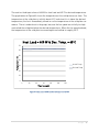
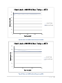
channels. Using ANSYS software, the thermal resistance of the cold plate was
determined for each of these cases using two different convective heat transfer
coefficients. The values of these convective heat transfer coefficients were selected
based on a range of published values for boiling refrigerant. Table 2 shows the results
of the FEA.
P a g e | 14