1
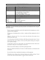
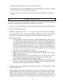
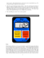
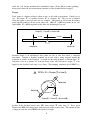
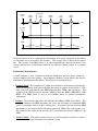
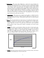
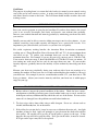
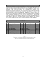
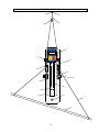
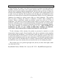
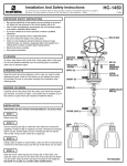
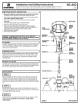
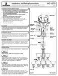
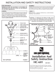
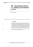
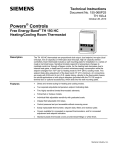
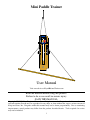
Mini Paddle Trainer
Mini
Paddle Trainer
Performance
Force (Lb.)
Time (m:s)
Speed (mph)
Distance (mi)
Power (W)
Energy (Cal)
Cad. (SPM)
Strokes
On / Off
User Manual
Visit our website at: KayakBalanceTrainer.com
Read the material before using this product.
Failure to do so can result in serious injury.
SAVE THIS MANUAL.
Copyright 2012-2015 by Korpi and Sons, Inc. All rights reserved. No portion of this manual or any
artwork contained herein may be reproduced in any shape or form without the express written consent of
Korpi and Sons, Inc. Diagrams within this manual may not be drawn proportionally. Due to continuing
improvements, actual product may differ from the product described herein. Tools required for service
may not be included.
1
Name ______________________________ Purchase Date ___________ Serial Number ________
INTRODUCTION
The Mini Paddle Trainer (MPT) is an adaptive core strength builder designed for
people who want the option of using their own chair, even people who use wheelchairs will
find the MPT an excellent way to exercise. People learning how to kayak or paddle a stand
up paddleboard will find the MPT a fun way to train without having to get into the water.
The MPT is also an excellent alternative for training during bad weather to maintain the core
and upper body strength needed for successful watersporting.
The MPT provides the
exerciser with paddle strokes that mimic the on water experience.
The MPT is fully
adjustable to accommodate a wide range of exercisers depending on their strength and
individual preferences such as sitting for kayak training and standing for paddleboard
training. The wall-mounted exerciser requires a minimal amount of space when not in use.
Each MPT is hand built in America by wood craftspeople.
1. The wall-mounted base is made of natural cedar clear coated to allow the wood
grain to come through.
2.
The paddle is made from ash a hardwood known for strength and durability.
3. The flywheel is designed to maximize glide time that closely mimics the on water
gliding feeling.
4. Adjustable settings allow for a wide range of force needed for various paddlers
capabilities and may be increased as strength is built up.
5. The wall trainer is designed with a smooth, durable and reliable rope drive
mechanism.
SAVE THIS MANUAL
You will need this manual for the safety warnings and precautions, operating, inspection,
maintenance and cleaning procedures, parts list and assembly diagram. Keep your invoice
with this manual. Keep this manual and invoice in a safe and dry place for future reference.
2
PRODUCT SPECIFICATIONS
Power produced
Dimensions
Weight
Designed use
Display
Intensity
Drive type
Power requirements
Materials
Frame
Rope
Pulley blocks
Up to 250W at max pulling force
Wall unit: 20”L x 7”W x 10”H, Paddle: 61”
12 pounds
Consumer
Pulling Force (pounds); Paddling time (Minutes:Seconds);
Velocity (Miles/hour); Distance (Miles);
Power (Watts); Energy (calories)
Cadence (Strokes/Minute), Stroke Count
Variable setting of pulling force using nylon cord on flywheel
Rope and drive pulley to spin flywheel
2 batteries type CR123, included
Finished wood
5/16” braided synthetic fiber
Marine low friction
GENERAL SAFETY RULES AND PRECAUTIONS
WARNING: Read the following important precautions and information before using the
Mini Paddle Trainer.
-
Exercise can present a health risk; consult with a physician before beginning any exercise
program with this equipment.
-
Warming up and stretching before and after a workout will help minimize the risk of
injuries.
-
Maintain a clear area of 3.5 to 4 feet on the sides and back of the trainer for an
unobstructed paddle stroke.
-
Use a firm grasp on the flywheel and frame while lifting and moving the trainer. Do not
lift the unit by the ropes or pulleys as these may shift position causing you to drop the
unit or pinch your fingers.
-
Use the trainer on a flat, level, sturdy surface, away from moisture and dust. Do not store
the trainer in a damp area or covered patio, or near water.
-
The user may remain standing or seated while operating the trainer.
-
Increase the duration and intensity of exercise in small increments to avoid muscle strain
and soreness.
-
If you feel faint or dizzy, immediately discontinue use of this equipment.
-
Watch what you are doing, and use caution and common sense while exercising. Do not
use the trainer while under the influence of drugs, alcohol or medication.
3
-
Keep other people and pets away from the trainer when in use.
-
Always make sure screws and attachments are secured tightly prior to each use. Inspect
and replace any frayed cords, rubber bands and rope.
-
Do not attempt to use your trainer for any purpose other than the purpose for which it is
intended.
ASSEMBLY INSTRUCTIONS
The unit has been partially disassembled for shipment in two boxes. The long mailing tube
contains the paddle and the rectangular box contains the rest of the unit.
1. Locate a clear area of roughly 6 foot square that will not interfere with the paddling motion.
2. Remove all items from the boxes.
3. The MPT is supplied with 2 each – ¼ x 3” lag bolts and washers to facilitate mounting the
unit to a plasterboard wall. If you are mounting to another type of wall - cement, cinder
block etc please consult your local hardware store for appropriate mounting hardware.
4. For plasterboard walls:
a. Use a stud finder to locate the wall studs. Standard construction has stud spacing of
16” with center-to-center spacing between studs. Select the stud with adequate area
to swing the paddle. Mark the stud location on the wall. Position the Mini Trainer
approximately 2-14 inches off of the floor; it can be positioned immediately above
the floor molding or baseboard radiators. Use a support to rest the trainer on, so
that it does not shift while marking the drill spots. Make sure the mounting holes
align with the stud and the unit is vertical. Mark the positions of the two mounting
holes with a center tap or Phillips screwdriver.
b. Remove the unit and drill two 316” pilot holes at the marked points.
c. Re-position the unit back in place and install the two lag bolts with washers.
Tighten mounting hardware.
d. Mark a position on the same stud approximately 6 to 7 feet off the floor. Drill a
5/32” pilot hole at this point. Screw the swage hook into the wall at this point.
e. Connect the upper pulley bungee cord to the swag hook.
f. Remove the two Performance Monitor (PM) mounting screws from the top of the
main unit. Use these screws to mount the PM to the main unit. Plug the RJ12 cable
from the magnetic pickup into the bottom of the PM.
5. Attach the rope ends to the paddle grooves; pull the rope tight so the slipknot makes a tight
fit in the paddle grooves.
6. Adjust the flywheel resistance force as follows: Press the cord clamp release button on the
top of the PM and pull up the cord slightly to remove pressure of the cord on the flywheel.
Paddle a few easy strokes to accelerate the flywheel to a moderate speed. Pull up on the
cord so that the flywheel is slowing gradually and set the cord clamp to this position. A
light force slows the flywheel to a stop in about 20 seconds, a heavy force stops it in less
4
than 3 seconds. Adjust the flywheel force so the resistive force is comfortable for you. We
recommend setting at a light force when starting out.
7. Adjust the swage hook bungee length as follows. Press the cord clamp release button on
bungee to shorten or lengthen the distance between the swag hook and the upper pulley.
This bungee adjusts the tension of the rope on the drive pulleys. To increase rope tension,
either shorten the bungee or move back slightly from the trainer. To decrease rope
tension, either lengthen the bungee or move slightly closer to the trainer.
8. Turn on the PM power switch. You are ready to paddle.
PERFORMANCE MONITOR
Mini
Paddle Trainer
Performance
Force (Lb.)
Time (m:s)
Speed (mph)
Distance (mi)
Power (W)
Energy (Cal)
Cad. (SPM)
Strokes
On / Off
Basics
The Performance Monitor is used to provide feedback on eight different factors that indicate
the level of performance being exerted by the athelete. There are four LED lights that light
up corresponding to the specific factor being displayed. The LEDs light up yellow to
indicate factors in the yellow box or red to indicate factors in the red box; for example, when
the third LED lights up red, the factor being displayed is Energy in calories. The eight
factors are displayed in turn in a cycle that takes 30 seconds and then repeats itself. If the
flywheel stops rotating for more than 4 minutes, the power turns off to conserve battery
energy. When the flywheel stops, the factors on the left side, the “yellow” factors read zero,
5
while the “red” factors maintain their accumulated values. If the athlete resumes paddling
before power turns off, the measurements continue as if the flywheel had not stopped.
Torque
Static torque is a balance of forces about an axis or axle with no movement. Consider a sea
saw. The torque “T” is a product of force “F” at a distance “D”. The sea saw is balanced
when the torque is equal on each side, for example: 100 pounds at 6 feet from the balance
point with 60 pounds at 10 feet on the other side. 100# x 6’ = 600 foot-pounds on one side
equals 60# x 10’ = 600 foot pounds on the other side balancing the sea saw.
Torque(T) = Force(F) x distance(D)
6 feet
10 feet
100 pounds
60 pounds
Dynamic torque is an un-balanced force about an axis or axle that causes a rotational
movement. Consider a flywheel mounted on an axle with a string wrapped around the
perimeter or outside of the flywheel. A weight on the string produces a constant force “F”
such that a force at a distance “D” from the center of the axle will cause a torque “T” to be
applied to the flywheel and cause it to rotate. The changing rotational speed “RPM” is a
RPM = Kf x Torque(T) x time(t)
bearing
D
bearing
Force
Torque(T) = Force(F) x distance(D)
product of the flywheel inertial mass “Kf” times torque “T” times time “t”. For a given
flywheel the RPM will change more with increased torque or more time. The amount of time
is longer to reach the desired RPM if the flywheel is larger.
6
Average
Paddle
Force
Right
Stroke
Left
Stroke
Right
Stroke
Left
Stroke
Right
Stroke
time
0
Resistive
Force
+
time
0
RPM
time
0
In flywheel based exercise equipment the intermittent force pulses generated by the athlete
are smoothed out or averaged by the flywheel. The average force is shown by the dotted
line. The resistive or breaking force is of equal magnitude but opposite direction to the
average athletic force and therefore balanced out when the athlete paddles at a constant
speed.
Performance Measurements
A small computer is used to monitor a magnetic pickup that generates pulses whenever a
flywheel magnet passes the pickup. The computer calculates several factors and displays
performance information for the athlete. These factors are explained below.
1. Flywheel Speed: The computer uses a high speed counter to accurately measure the time
between each pickup signal pulse indicating the period of rotation of the flywheel. This
time is inversely proportional to the RPM of the flywheel: RPM = 60 / period(sec). For
example if the flywheel period measures 0.050 sec then the RPM is 60/0.050 = 1200
RPM. The RPM factor is used in the formulas below to produce performance
information.
2. Cadence: The cadence is the stroke rate in Strokes Per Minute (SPM) of the athlete. The
computer monitors the RPM parameter and stores the maximum and minimum RPM
values to determine when a stroke is taking place. It measures the time between RPM
maximums i.e. the stroke period to determine stroke rate: SPM = 60 / stroke period (sec).
For example if the stroke period measures 0.75 second then the cadence is 60/0.75 = 80
SPM.
3. Stroke Counter: The stroke counter starts at zero and increments each time a stroke is
detected. It counts the total strokes of a workout session.
7
4. Pulling Force: The average stroke pulling force is equal to the average breaking force
caused by a cord around the flywheel. The amount of resistive or slowing torque may be
measured by measuring the time it takes to slow down using the formula: change in RPM
= Kf x Torque x time as presented earlier. The amount of resistive torque may be
accurately measured by comparing the time for one flywheel rotation compared to the
time of the previous rotation while the flywheel RPM is slowing down. The accelerating
torque is similarly calculated while the flywheel is speeding up. During the forward
stroke, the athlete supplies the torque to accelerate the flywheel plus the torque to
overcome the resistive torque of the braking cord. The pulling force is the sum of the
torques divided by the radius of the drive pulley.
5. Average Power: The average power produced by the athlete is calculated from the
formula: Power (W)= 0.01183 x Average Torque(T) x RPM where average torque is in
inch-pounds and power is in Watts. This parameter indicated the level of effort expended
by the athlete.
6. Energy: The energy data indicates the calories that were used during the workout session.
The calories are equal to the average power times time: Calories (C) = 5 x Power (W) x
time (hour). Thus if you exercise for 1 hour at a 100Watt power level the computer
estimates 500 calories were used. The actual calories used, however, varies considerably
based on athletes weight, cardiovascular condition, conditioning of the muscle groups
and technique.
7. Velocity: The velocity or speed parameter indicates the velocity of a boat on the water.
The power needed to produce velocity is an exponential curve; see below. The formula
is: Velocity = Kv * (Power) ^ 1/3 where Kv, for narrow watercraft, is 2.8 meter/sec or
1.585 MPH. For example when power = 256W or about 1/3 HP; Velocity = 1.585 x
(256) ^ 1/3 equals 10.04 mph as shown on the graph. This power vs. velocity curve is
stored in the computer and the velocity parameter is generated from this curve.
12
10
8
Speed
(MPH)
6
4
2
0
01
5
9
13
17
21
25
29 33(W)
37
Power
41
45
49
53
57
61
256
8. Distance: The distance parameter indicates the distance traveled by the boat. The distance
is calculated by multiplying the velocity factor by time.
8
9. Time: The time parameter indicates the duration of the workout session and is produced
by the computer clock whenever the computer detects that the athlete is providing power
to the flywheel.
OPERATING INSTRUCTIONS
1. Take a few minutes to warm-up and stretch your body.
2. Take your position in front of the trainer with feet on the floor and slowly move the
paddle shaft in a wide controlled stroke to see that there are no obstructions to a full
paddle movement. Reposition yourself or move objects as necessary so an unobstructed
stroke is obtained.
3. Adjust the bungee cord and flywheel resistance settings if necessary, reference directions
in the assembly instruction section.
4. Use proper paddling posture and technique to prevent common muscle and joint injuries.
Sit with an upright or slightly leaning forward posture. Rely on your core muscles and not
just your arm muscles for power. Start by holding the paddle at arms length with your
arms parallel at shoulder width. If you lock your elbows you will find the only way to
paddle is to rotate your torso and use your core muscles. Then, bend your elbows slightly
and continue the same motion with your arms transferring the power from the core to the
push and pull motion of the paddle.
5. Paddle at the desired cadence and duration to your liking and comparable to on water
exercise.
6. After paddling, take a few minutes to cool down and stretch again.
WARM-UP AND COOL DOWN
Warm-Up
The purpose of warming up is to prepare your body for exercise and to minimize injuries.
Warm up for two to five minutes before strength training or aerobic exercising. Perform
activities that raise your heart rate and warm the working muscles. Activities may include
brisk walking, jogging, jumping jacks, jump rope and running in place.
Stretching
Stretching while your muscles are warm after a proper warm-up and again after your strength
or aerobic training session is very important. Muscles stretch more easily at these times
because of their elevated temperature, which greatly reduces the risk of injury. Stretches
should be held for 15 to 30 seconds. Do not bounce.
Remember to always check with your physician before starting any exercise program.
9
Cool-Down
The purpose of cooling down is to return the body back to its normal, or near normal, resting
state at the end of each exercise session. A proper cool-down slowly lowers the heart rate
and allows blood to return to the heart. The cool-down should include stretches after each
training session.
EXERCISE GUIDELINES
Base your exercise program on your physical condition. If you have been inactive for several
years or are severely overweight, start slowly and increase your workout time gradually.
Increase your workout duration and intensity gradually by monitoring your heart rate while
you exercise.
Initially you may only be able to exercise within your target zone for a few minutes. As you
continue exercising, your aerobic capacity will improve over a period of 6-8 weeks. It is
important to pace yourself while you exercise so you don’t tire too quickly.
For cardio respiratory training benefits, the American Heart Association recommends
working out at a Target Heart Rate Zone of between 60% and 75% of your maximum heart
rate based on age. To predict your maximum heart rate, use the formula 220-Age =
maximum heart rate. For example, if you are 40 years old, your max rate is: 220-40 = 180.
Your exercise heart rate range is then 0.6x180=108 to 0.75x180=135 beats per minute. If
just starting out, work out at the low end of your target heart rate zone. As your aerobic
capacity improves, gradually increase the intensity of your workout by increasing your heart
rate.
Measure your heart rate periodically during your workout with a heart rate monitor or by
counting the number of heart beats for six seconds and multiplying the number by 10 to get
your heart rate. For example if your six second heartbeat count is 15, your heart rate is 150
beats per minute. Adjust your exercise intensity such that your heart rate is within proper
range for your age.
TRAINER INSPECTION, MAINTENANCE AND CLEANING
1. Before each use, inspect the general condition of the trainer. Check for loose screws,
misalignment or binding of moving parts, frayed rubber bands rope or cords, cracked or
broken parts and any condition that may affect the safe use of the trainer. Do not use the
trainer if it is damaged; have the problem corrected before further use.
2. To clean, wipe with a damp cloth, using a mild detergent. Never use solvents such as
alcohol, trichloroethylene, etc on the trainer.
3. If the rollers do not spin freely, it may be necessary to lubricate the main axle. Any light
machine oil may be used. Apply oil sparingly to space between the shaft collar and the
drive pulley. Be careful not to get any oil on the pulley v-groove or the rope. If this
happens, the rope will fail to grip the roller. If oil gets on the roller, it must be cleaned.
If oil gets on the rope it may have to be replaced.
10
PLEASE READ THE FOLLOWING CAREFULLY
THE MANUFACTURER AND/OR DISTRIBUTOR HAS PROVIDED THE PARTS LIST
AND LOCATION DIAGRAM IN THIS MANUAL AS A REFERENCE TOOL ONLY.
NEITHER
THE
MANUFACTURER
OR
DISTRIBUTOR
MAKES
ANY
REPRESENTATION OR WARRANTY OF ANY KIND TO THE BUYER THAT HE OR
SHE IS QUALIFIED TO REPLACE ANY PARTS OF THE PRODUCT. IN FACT, THE
MANUFACTURER AND/OR DISTRIBUTOR EXPRESSLY STATES THAT ALL
REPAIRS AND PARTS REPLACEMENTS SHOLD BE UNDERTAKEN BY CERTIFIED
AND LICENSED TECHNICIANS, AND NOT BY THE BUYER. THE BUYER
ASSUMES ALL RISKS AND LIABILITY ARISING OUT OF HIS OR HER REPAIRS TO
THE ORIGINAL PRODUCT OR REPLACEMENT PARTS THERETO, OR ARISING
OUT OF HIS OR HER INSTALLATION OR REPLACEMENTS PARTS THERETO.
PARTS LIST
Part
1
2
3
4
5
6
7
8
9
Description
Flywheel
5/16” rope
Paddle shaft
Drive pulley
Rope guide pulley
Rope fairlead guide
Performance meter
Swag hook
Flywheel braking cord
No.
Part
Description
015-01 10 Upper pulley
015-02 11 Axle
015-03 12 Bungee cord
015-04 13 Shaft collar
015-05 14 Frame
015-06 15 Cord lock
015-07 16 Mounting hardware
015-08 17 Magnetic pickup
015-09 18 Drive pulley band
Note:
Some parts are listed and shown for illustration purposes only,
and are not available individually as replacement parts.
11
No.
015-10
015-11
015-12
015-13
015-14
015-15
015-16
015-17
015-18
LOCATION DIAGRAM
8
15
12
10
7
Paddle
Mini Trainer
Performance
6
Force (Lb.)
Time (m:s)
Speed (mph)
Distance (mi)
Power (W)
Energy (Cal)
Cad. (SPM)
Strokes
17
On / Off
5
13
11
4
1
9
16
14
2
3
12
WARRANTY
Korpi and Sons, Inc. makes every effort to assure that its products meet high quality and
durability standards and warrants to the original purchaser that for a period of ninety days
from the date of purchase that the motor/generator, the belts and rope are free of defects in
materials and workmanship. Korpi and Sons, Inc. also warrants to the original purchaser, for
a period of one year from the date of purchase, that all other parts and components of the
product are free from defects in materials and workmanship (90 days if used as common gym
equipment; for example in a school, exercise club or as rental equipment). This warranty
does not apply to damage due directly or indirectly, to misuse, abuse, negligence or
accidents, repairs or alterations outside our facilities, normal wear and tear, or lack of
maintenance. We shall in no event be liable for death, injuries to persons or property, or for
incidental, contingent, special or consequential damages arising from the use of our product.
Some states do not allow the exclusion or limitation of incidental or consequential damages,
so the above limitation of exclusion may not apply to you. THIS WARRANTY IS
EXPRESSLY IN LIEU OF ALL OTHER WARRANTIES, EXPRESS OR IMPLIED,
INCLUDING THE WARRANTIES OF MERCHANTABILITY AND FITNESS.
To take advantage of this warranty, the product or part must be returned to us with
transportation charges prepaid. Proof of purchase date and an explanation of the complaint
must accompany the merchandise. If our inspection verifies the defect, we will either repair
or replace the product at our election or we may elect to refund the purchase price if we
cannot readily and quickly provide you with a replacement. We will return repaired products
at our expense, but if we determine there is no defect, or that the defect resulted from causes
not within the scope of our warranty, then you must bear the cost of returning the product.
This warranty gives you specific legal rights and you may also have other rights, which
vary from state to state.
Kayak Paddle Trainer, PO Box 1161 – Syosset, NY 11791 – [email protected]
13