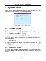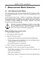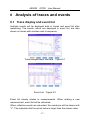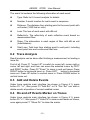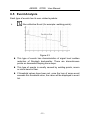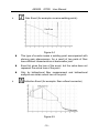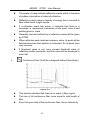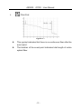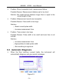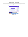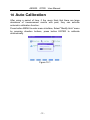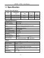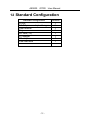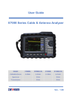
1
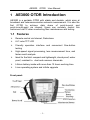
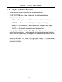
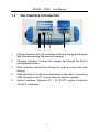
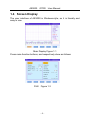
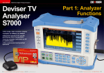
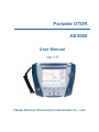
Portable OTDR AE3000 User Manual ver 1.0 Tianjin Deviser Electronics Instrument Co., Ltd. PREFACE This manual is an operating instruction of product AE3000, which is the OTDR product of Deviser Corporation. If the content in this manual changed, there will be extra notice. If there are some errors in this manual during compiling and printing, Deviser doesn't undertake the responsibility. Reserve all copyrights. Without permission of Deviser Corporation, text of this manual can not be photocopied, copied and translated. If quote from this manual, please give chapter and verse for it. Security Notice: Following security notices will be used in this manual. About operation information and notice of AE3000. About important operation information of AE3000, if user breach, may bring difficulty to use. “Attention” alerts you to any condition that could spoil the AE3000 equipment or lose important data. “Danger” alerts you to any condition that could cause personal injury. Security of Laser Sender: AE3000 has 1310nm and 1550nm high power semiconductor laser sender, its security obey: FDA21CFRξ1040.10 standard IEC825-1(EN60825-1:1994) Ⅲ b standard Caution Mark: CONTENT 1 AE3000 OTDR Introduction ...................................................... 1 1.1 Features ................................................................................... 1 1.2 Keyboard introduction ............................................................... 2 1.3 Top Interface Introduction ......................................................... 3 1.4 Screen Display ......................................................................... 4 1.5 Power System .......................................................................... 6 1.6 Upgrade .................................................................................... 6 2 Security Warnings..................................................................... 7 2.1 Laser Security Information ........................................................ 7 2.2 Electric Safety Information ........................................................ 7 3 Measurement Preparations ...................................................... 8 3.1 Measurement Preparations ...................................................... 8 3.2 On-off........................................................................................ 9 4 System Setup ......................................................................... 10 4.1 Language Choice ................................................................... 10 4.2 Set Time and Date Setup ....................................................... 10 4.3 Unit Setup ............................................................................... 10 4.4 Brightness Setup .................................................................... 10 4.5 Auto Power Off Time Setup .................................................... 11 5 Measurement Mode Selection ................................................ 12 5.1 Auto Measurement Mode ....................................................... 12 5.2 Normal Measurement Mode ................................................... 13 5.3 Other Measurement Parameter Setup .................................... 14 6 Analysis of traces and events ................................................. 17 6.1 Trace display and event list .................................................... 17 6.2 Trace Analysis ........................................................................ 18 6.3 Add and Delete Events ........................................................... 18 6.4 On and off Events Marker on Traces ...................................... 18 6.5 Event Analysis ........................................................................ 19 7 File Management .................................................................... 23 7.1 Storage ................................................................................... 23 7.2 Load ....................................................................................... 23 7.3 Deletion .................................................................................. 24 7.4 Copy ....................................................................................... 24 7.5 Create Folders ........................................................................ 24 7.6 File Printing............................................................................. 24 8 Maintenance ........................................................................... 25 8.1 Cleanness .............................................................................. 25 8.2 Laser Interface Maintenance .................................................. 25 9 Problem and Fault Diagnosis.................................................. 28 9.1 Device Problem ...................................................................... 28 9.2 Measurement setup problem .................................................. 29 9.3 Automatic Diagnosis ............................................................... 30 10 Auto Calibration ...................................................................... 32 11 Specification ........................................................................... 33 12 Standard Configuration ........................................................... 35 13 Warranty ................................................................................. 36 13.1 General Information ................................................................ 36 13.2 Responsibility Avoid ................................................................ 36 13.3 Service and Maintenance ....................................................... 36 AE3000 OTDR User Manual 1 AE3000 OTDR Introduction AE3000 is a portable OTDR with stable and durable, which aims at broadcast and telecommunication network measurement. It is also the first OTDR to achieve data share of point-to-point and point-to-multi-point via internet. Users can remotely control this instrument via PC when conducting fiber maintenance and testing. 1.1 Features Remote control via Internet, Data share 6.4” color TFT LCD Friendly operation interface and convenient One-button testing High-speed signal processing, less measurement time, and faster result analysis. Ideal for the field: compact and lightweight, shock proof, water proof, resistant to dust and common chemicals. Lithium battery inside with more than 10 hours working time Linux operating system and infinite upgrade Front panel: -1- AE3000 OTDR User Manual 1.2 Keyboard introduction On-off Button: Use this button to turn device on/off START/STOP Button: Use this button to start/stop testing Main-function Buttons: FILE——File operation:Such as storing, load and deletion SETUP——Measurement, Analysis and system Setup. MENU——Information of system version, upgrade and help AUTO——Automatic measurement shortcut key Soft Button: Buttons"F1, F2, F3, F4, F5"——when pressed main-function buttons, it will enter into corresponding user interface, and F1 to F5 respectively correspond to the software buttons on the screen Direction Buttons: "up, down, left, right and ENTER"——when setup and trace analysis, user can choose the direction and zoom with direction buttons -2- AE3000 OTDR 1.3 User Manual Top Interface Introduction 1 2 3 4 5 1. Charge Indicator: Red light indicates battery is charging and green light indicates battery has been full charged 2. Charging Interface: Connect the charger and charge the built-in rechargeable battery 3. RJ45 Interface: Access the Internet for remote control and data sharing 4. USB Interface (Principal and subordinate mode each): Connecting USB, Keyboard and PC to copy data and system upgrade 5. Optical Interface: Standard FC / PC,SC/PC optical Connector (SC/APC is optional) -3- AE3000 OTDR User Manual 1.4 Screen Display The user interface of AE3000 is Windows-style, so it is friendly and easy to use. Main Display Figure 1.1 Press main-function buttons, and respectively show as follows: FILE Figure 1.2 -4- AE3000 OTDR User Manual SETUP Figure1.3 MENU Figure 1.4 -5- AE3000 OTDR 1.5 User Manual Power System AE3000 use following powers: AC Adapter/Charger (Charge automatically when connected AC adapter/charger) Rechargeable Batteries: Li-ion Battery with a long continuous power supply (Battery works automatically when disconnected the AC adapter/charger) Li-ion Battery is light, safe and reliable. It can be charged and discharged more than 300 times with proper use. Must charge Li-ion Battery with the charger that provided with AE3000, otherwise the battery may be damaged. In low temperature case, the discharge capacity of Li-ion battery will deteriorate. When use it at low temperatures, the time of power supply will be shorter 30% max than normal temperature. 1.6 Upgrade Two Cases: Under normal condition, copy the upgrade program to USB disk, then insert USB disk into USB interface of AE3000. It will upgrade automatically when boot. Under system breakdown condition, the system can be restored through USB interface. Please keep USB cable well. -6- AE3000 OTDR User Manual 2 Security Warnings 2.1 Laser Security Information The OTDR laser interface and end of pigtail can’t be aimed at eyes on no condition. Otherwise, It may damage vision, even blindness! OTDR uses powerful semiconductor laser, its strong power is sufficient to injure personal’s eyes, so please must pay great attention. The correct way is that firstly take off the cap of OTDR laser interface on condition of power off, then connect fiber and boot OTDR to measure. After measurement, firstly turn off OTDR, then disconnect fiber, finally put on the cap of OTDR laser interface immediately. It should be noted that the pigtail, which will be connected to OTDR, must be clean. Forbid connecting fiber with grease. Otherwise, the instrument will not work properly. OTDR is engineering equipment. When used at the field, it may be failed to connect because of dirt into fiber connector. So must pay great attention. The correct way is: Before fiber is connected to the laser interface, its end should be cleaned by ethanol. After Alcohol is volatilized, the fiber can be connected to instrument. When fiber is taken off from device, the laser interface should be covered with the cap. 2.2 Electric Safety Information The use of electrical equipment will be a serious security threat in the vicinity of flammable gases or fumes. In order to avoid electric shock, if any part of the appearance of instrument has been damaged, do not operate it. Only authorized personnel of our company can debug, maintain and repair this device with power. -7- AE3000 OTDR User Manual 3 Measurement Preparations 3.1 Measurement Preparations Before the first use of the OTDR equipment, please charge the battery. When using OTDR equipment to measure, the operator should ensure that the type of fiber connector consistent with the equipment. Otherwise, it will affect accuracy of measurement. Generally, OTDR uses FC/PC fiber connector (jumper). Accordingly, operator should prepare measurement pigtail or adapter that matches. Usually, operator will face two situations. One is that measured-fiber has been installed and measured-side has been installed on the rack through some type of connector. In this case user should select FC/PC-XX/XX jumper to connect. FC/PC-side connects OTDR. XX/XX is the type of measured-fiber terminal adapter on the rack, such as FC/PC, FC/APC, SC/PC, SC/APC and so on. The other is that measured-fiber is a bare fiber. In this case user should use FC/PC bare fiber adapter or weld a jumper by yourselves. Before using OTDR to measure, Please prepare cleaning tools for fiber interface, It is suggested to prepare anhydrous alcohol, absorbent cotton or fiber cleaner. Otherwise, it will affect measurement accuracy, seriously will damage equipment. Suggest that users use an additional fiber to reduce dead zone. Any OTDR has measurement dead zone. If user is concerned in near end dead zone, Please use an additional length of fiber, whose length is known, to "eliminate" dead zone. The length of additional fiber is determined by user’s experience. When using the measurement results, user should avoid this section of fiber. -8- AE3000 OTDR User Manual 3.2 On-off Press on-off button, the on-off indicator light turn red, then OTDR equipment start booting. Press on-off button again, a dialog box about power off reminder will appear. Choose “off” to power off equipment, and “cancel” to maintain power on state. Press on-off button for seconds will force device to power off. -9- AE3000 OTDR User Manual 4 System Setup Press SETUP to enter setup interface (as shown in Figure 1.3), and then press button F3 to enter system setup interface. System Setup Figure 4.1 4.1 Language Choice In System Setup Interface: When the red rectangle frame surround "Language" menu, pressing UP and DOWN button to switch languages. 4.2 Set Time and Date Setup In System Setup Interface: Select "Time" and "date" menu by pressing LEFT and RIGHT button. Then modify time and date by pressing UP and DOWN button. 4.3 Unit Setup In System Setup Interface: Select "Unit" menu by pressing LEFT and RIGHT button. Then switch between kilometer and mile by pressing UP and DOWN button. 4.4 Brightness Setup In System Setup Interface: Select "Brightness" menu by pressing LEFT and RIGHT button. Then adjust brightness by pressing UP and DOWN button. - 10 - AE3000 OTDR User Manual 4.5 Auto Power Off Time Setup In System Setup Interface: Select "Auto Off" menu by pressing LEFT and RIGHT button. Then set auto off time by pressing UP and DOWN button. - 11 - AE3000 OTDR User Manual 5 Measurement Mode Selection 5.1 Auto Measurement Mode Auto measurement mode will automatically estimate the length of fiber, set sampling parameters, get trace and show a timetable and show trace result. In auto measurement mode, in addition to wavelength, measurement time and group index of refraction, other settings will be automatically configured according to measurement mode by instruments, users do not need to setup. AE3000 will configure, measure, and show measurement results automatically. Generally, automatic measurement function is used when user is inexperienced for OTDR operation. User can firstly use auto mode, and then setup and measure manually base on the results of automatic measurement. Want to obtain trace in auto mode: 1.Clean connector correctly 2.Connect fiber to optical connector 3.Press AUTO button to setup ①Change index of refraction by pressing UP and DOWN button ②Switch between index of refraction menu and wavelength menu by pressing LEFT and RIGHT button ③Press ENTER button for confirmation. 4.Press F1 button to start automatic measurement. After pressing F1 button, the instrument will work as follows: ①Check fiber connection, if fiber connection has problems, the process will be suspended ②Parameters configuration ③Measurement capture, refresh trace on the screen and also there - 12 - AE3000 OTDR User Manual is schedule indication. ④Complete measurement and analyze the results ⑤Show captured parameters and results During measurement, press AUTO will terminate the process. 5.2 Normal Measurement Mode In normal measurement mode, users can set all measurement parameters and finish testing manually. Parameter setting methods are as follows: Under main interface, press button SETUP to enter into setup interface, as shown in Figure 1.3. Set wavelength, measure mode, distance range, pulse width, acquisition time and smoothing by direction button. Press button F5 to quit setup interface. 5.2.1 Distance Range Setup AE3000 have 8 distance range: 2km, 5km, 10km, 20km, 40km, 80km, 160km, 200km. User should set proper distance range according to actual length of fiber or the length obtained from auto mode before measurement. Set improper distance range will affect measurement. In order to make user’s setup more effective, AE3000 associate pulse width with distance. Please refer to Table 5.1. Distance Pulse width 5ns 10ns 20ns 50ns 100ns 2km 5km 10km √ √ √ × × × √ √ √ × × × √ √ √ 20km × × × × √ - 13 - 40km × × × × × 80km × × × × × 160km 200km × × × × × × × × × × AE3000 OTDR User Manual Distance Pulse width 200ns 500ns 1000ns 2000ns 5000ns 10000ns 20000ns 5.2.2 2km 5km 10km × × × × × × × × × × × × × × 20km √ √ × × × × × × × × × × × × 40km × √ √ √ × × × 80km × × × × √ √ √ 160km 200km × × × × × × √ × × × × × × √ Pulse Width Setup Pulse width is width of optical pulse high-power signal that immit to measured fiber. The wider Pulse width is, the farther OTDR can detect effectively, but at the same time the dead zone is larger. Therefore, the choice of pulse width is related to distance of measured fiber. The distance is longer, the pulse width should be wider. AE3000 associate pulse width with distance. When using OTDR, user can choose proper pulse width according to experience. 5.2.3 Acquisition Time Setup The longer acquisition time is, the better signal’s signal-to-noise improves and more accurate measurement results are. User should choose a reasonable acquisition time. Acquisition time is proportional to measurement dynamic. 5.3 Other Measurement Parameter Setup 5.3.1 Smoothing Setup There are noises on OTDR trace usually. The noises will be reduced through a series of average, but can not be completely eliminated, which is called trace noises. Trace noises will cause measurement errors. For the convenience of users, AE3000 offer a smoothing switch. When switching it on, trace noises will be "filtered". But at the same time it will cause larger dead zone. Users can determine to switch it on or off according to actual situation. - 14 - AE3000 OTDR User Manual 5.3.2 Index of Refraction & Scattering coefficient Setup Index of refraction and scattering coefficient can be configured in limit menu. Method is as follows: When under main Menu, press button SETUP to enter into setup interface. Press button F2 to enter limit menu. Switch among Splice Limit, Reflec. Limit, Slope Limit, Fiber End Limit, Index and Scatter Coeff by pressing LEFT and RIGHT button. When Index menu or Scatter Coeff menu is selected, change their values through UP and DOWN button. Users can change index of refraction value from 1.30000 to 1.70000. Changing index of refraction will changes measurement results. Index of refraction is provided by optical or cable manufacturers It is suggest that users use group index of refraction of a length-known fiber and remember it. Scattering coefficient usually get from optical cable manufacturers. Changing scattering coefficient will make event loss and reflectivity changed. 5.3.3 Event Limit Setup Event limits include splice limit, reflectivity limit, slope limit and fiber end limit. Methods refer to 5.3.2. Press F5 to exit. If want to display all events, please ensure that all limit items are chose in setup interface. Whether show one specified event depends on the choice of threshold values of attenuation, slope and reflectivity. When any of above values exceed threshold value, the event and its information will be shown in events list. Event reflectivity will always be measured, unless all other items can not be displayed. For example: When peak is saturated or event is submerged in noises, instrument will not give accurate measurement - 15 - AE3000 OTDR User Manual value, such as -30dB, It will read >-30dB which means the reflectivity worse than -30dB. Whether show slope value depends on the choice of threshold value of slope. When measurement value exceed threshold value, slope value will be shown. - 16 - AE3000 OTDR User Manual 6 Analysis of traces and events 6.1 Trace display and event list Analysis results will be displayed both in traces and event list after measuring. The events, which are displayed in event list, are also shown on traces with number mark in sequence. Trace Analysis Main Interface Event List Figure 6.1 Figure 6.2 Event list closely relates to measurements. When making a new measurement, event list will be refreshed. When reflection events are saturated, the maximum will be shown with ">". This indicates that the actual value is larger than the shown value. - 17 - AE3000 OTDR User Manual The event list contains the following information of each event: Type: Refer to 6.5 event analysis for details Number: A serial number for each event in sequence Distance: The distance from starting point to the event point with unit meter (1000 feet or mile) Loss: The loss of each event with dB unit Reflectivity: The reflectivity of each reflection event based on measurement fiber Slope: The attenuation in each region of fiber with dB as unit (loss/distance) Total Loss: Total loss from starting point to end point, including event point loss and continuous fiber loss 6.2 Trace Analysis Result analysis can be done after finishing a measurement or loading a trace file. First of all, Press F1 "cursor LR" to switch to cursor left, cursor right or cursor left and right, and then can move the selected cursor by LEFT and RIGHT button. Press F2 "Zoom" to zoom in and out traces. Press RIGHT button to horizontal zoom in. Press LEFT button to horizontal zoom out. Press UP button to vertical zoom in. Press DOWN button to vertical zoom out. 6.3 Add and Delete Events Under trace analysis main interface (as shown in Figure 6.1), press button F5 ">>", then press F3 "Add Evt" or F4 "Del. Evt" can add or delete events at position of current enabled cursor. 6.4 On and off Events Marker on Traces Under trace analysis main interface (as shown in Figure 6.1), press button F5 ">>", then press F1 "Hide Pic" to clear event marks on traces, once again press F1 "Show Pic" to show the marks. - 18 - AE3000 OTDR User Manual 6.5 Event Analysis Each type of events has its own related symbols: Non-reflective Event (for example: welding points) Figure 6.3 This type of events has characteristics of signal level sudden reduction of Rayleigh backscatter. There are discontinuous points on downward-sloping trace slope. This type of events is usually caused by welding points, macro or micro bend in fiber. If threshold values have been set, once the loss of some event exceeds this threshold value, the value will be displayed in event list. - 19 - AE3000 OTDR User Manual Gain Event (for example: reverse welding points) Figure 6.4 This type of events means a welding point accompanied with obvious gain phenomenon. As a result of two parts of fiber have different characteristics at backscatter joint. Event list gives the loss of the event, but the value does not represent the actual loss of the point. Only by bidirectional fiber measurement and bidirectional analysis can obtain actual loss of the point. Reflection Event (for example: fiber unfixed connector) Figure 6.5 - 20 - AE3000 OTDR User Manual The peaks of trace indicate reflection events which is because of sudden interruption of index of refraction. Reflection events make a majority of energy that is immited to fiber reflect back to light source. If a reflection event has arisen, it indicates that there is a connector or mechanical connection at the point, even a bad welding point or crack. Generally, loss and reflectivity of reflection events will be given by OTDR. When reflection peak reaches maximum value, its peak will be flattened because that detector is saturated. So its dead zone may increase. If threshold value is set, once exceed threshold value of reflectivity and/or connector, and this value will be displayed in event list. Continuous Fiber (it will be a diagonal without fiber faulty) Figure 6.6 This symbol indicates that there is no event in fiber region. The sum of all continuous fiber curve equal to total length of fiber. Event list gives loss of the continuous fiber, but no reflectivity. - 21 - AE3000 OTDR User Manual Fiber End Figure 6.7 This symbol indicates that there is no continuous fiber after the event point. The location of the event point indicates total length of entire optical fiber. - 22 - AE3000 OTDR User Manual 7 File Management 7.1 Storage AE3000 provide complete document storage and loading functions. It can store up to 1000 measurement files. User can name, number and annotate for each trace. It can also generate complete report sheet through PC analysis software. Under main interface, press FILE to enter file operation interface. (as shown in Figure 1.2) 7.1.1 Choice of Storage and File Naming Under main interface press FILE to enter file interface, press F1 "Store" and item "Filename" will be highlighted in green, press ENTER or F2 "Rename", then name the file through direction buttons. Switch to item "storage device" through UP and DOWN button, choose storage media among internal memory, SD and USB by pressing LEFT and RIGHT button. Also user can store the file into file folder created by user. 7.1.2 File Information Press F4 to switch to "File Info" column, then change information of "Corporation", "Operator", "Cable Ident.", "Fiber Number", "Fiber Nbr Inc.", "Origin Loc.", "End Loc." and " Direction ". the current selected item will be highlighted in green. 7.1.3 File Storage After completing setup of related file name, press F1 to store file, press F5 to exit. 7.2 Load Under main interface, press FILE to enter file interface, press F2 "Load", then choose media among internal memory, SD card and USB in column "Media List" by UP and DOWN, press ENTER or RIGHT to enter column "File List", choose the file you want to open by pressing UP and DOWN button, then press F1 "Open" to open the file. - 23 - AE3000 OTDR 7.3 User Manual Deletion Under main interface, press FILE to enter file interface, press F3 to enter "Delete" menu, choose storage media through UP and DOWN button, switch to File List column by ENTER or RIGHT, choose the files and folders you want to delete by UP and DOWN button, press F1 to delete this file, press F2 to delete all files in current folder. 7.4 Copy Under main interface, press FILE to enter file interface, press F4 to enter "Explore" menu, choose files and folders you want to copy (the same method as 7.3), press F1 and choose target storage media and path in pop-up menu through direction button, press F1 to copy. 7.5 Create Folders Under file operation interface, press F4 "Explore", then choose storage media in Media List menu by UP and DOWN button. Press F2 "Create Dir", and then name the folder through software keyboard, press F3 to confirm, then a folder will be created automatically. 7.6 File Printing Document can be print by computer analysis software. Press FILE button to enter file interface, and then user can switch menu of "Store", "Load", "Delete" and "Explore" through FILE button. - 24 - AE3000 OTDR User Manual 8 Maintenance 8.1 Cleanness Please keep OTDR equipment clean and avoid oil, dust and other dirt polluting the device. Avoid using AE3000 under relative humidity >90% condition and in the rain or water. Do not use organic solvent to clean the shell of equipment, but the dry cloth is suggested. Please protect surface of equipment and avoid scratches. 8.2 Laser Interface Maintenance 1. Take off the cover 2. Take off the dust proof cap - 25 - AE3000 OTDR User Manual 3. Rotate laser adapter by anti-clockwise 4. Draw laser adapter 5. Clean laser interface with absolute alcohol - 26 - AE3000 OTDR User Manual 6. Insert laser adapter into interface, then rotate it by clockwise - 27 - AE3000 OTDR User Manual 9 Problem and Fault Diagnosis 9.1 Device Problem 1 General Problem Problem: Black screen or fail to boot Possible Reason: battery has exhausted power Solution: Charging the battery by AC adapter/charger connected to an external power supply Problem: The screen is almost white or characters are fuzzy after boot Possible Reason: Brightness settings are not correct Solution: Enter setup interface to adjust brightness of screen 2 Fiber Connector Problem Measurement trace malfunctions caused by improper fiber connection show as follows: When measuring trace is shown in Figure 9.1, Figure 9.1 Possible Reason: ① use improper jumper interface ② connector is dirty - 28 - AE3000 OTDR User Manual ③ connector is aging Solution : ① replace jumper ② clean the connector ③ replace the connector When measuring trace as shown in Figure 9.2, Figure 9.2 Possible Reason: ① unreliable connection ② connector deviate ③ positioning bolt deviate Solution: ① reconnect ② replace the connector 9.2 Measurement setup problem Problem: Trace is too short and testing time is too long Possible Reason: measurement distance range set is too long Solution: Set proper distance range according to the actual length of fiber or the length measured through auto measurement mode - 29 - AE3000 OTDR User Manual Problem: Show incomplete track, measurement failure Possible Reason: Measurement distance set is too short Solution: Set measurement distance longer than or equal to the actual length of fiber Problem: Measurement events are incomplete Possible Reason: Pulse width is too large Solution: ① Select a small pulse width ② Increase measurement time Problem: Trace noise is too large Possible Reason: Pulse width is too small and scan time is not enough Solution: ① Increase measurement time ② Appropriately increase pulse width ③ Set smoothing to high level 9.3 Automatic Diagnosis When the fiber interface connect badly, the instrument will automatically diagnose and give remind messages. Figure 9.3 - 30 - AE3000 OTDR User Manual If there are other optical signals in measured fiber, AE3000 will automatically alarm. Figure 9.4 - 31 - AE3000 OTDR User Manual 10 Auto Calibration After using a period of time, if the users think that there are large deviations of measurement results with past, they can activate automatic calibration function: Press button MENU to enter menu interface, Select "Modify Auto" menu by pressing direction buttons, press button ENTER to calibrate automatically. Figure 10.1 - 32 - AE3000 OTDR User Manual 11 Specification Module Specifications type wavelength (nm) AE3000L 1310±20/1550±20 AE3000 1310±20/1550±20 AE3000H 1310±20/1550±20 attenuation dynamic range event dead dead zone (dB) zone (m) (m) 33/31 <5m <25m 35/33 <4m <20m 37/35 <3.5m <17m Main specifications Distance (Km) Pulse width(ns) Measurement time Distance uncertainty(m) Linearity Loss threshold(dB) Loss resolution(dB) Distance resolution(m) Sampling points Data storage 5m-200km 5ns-20μs user-defined(smart link) with real-time measurement function ±(0.5m ±0.003%×testing distance±resolution) ±0.05dB/dB 0.01dB 0.001dB 0.1m 64000 1000 item (AE3000L/AE3000) 2000 item (AE3000H) Others Display Fiber adapter Interface Battery Power Operating temperature 6.4 inch TFT colorized LCD FC/PC SC/PC USB(Principal and subordinate each)、SD、RJ45 built-in rechargeable Li-ion battery ( charging time <4 hours working time >10 hours) AC/DC adapter (Input AC90-240V ±10%,Output DC18V) 0℃~40℃ - 33 - AE3000 OTDR Storage temperature Comparative humidity Weight Dimensions (mm) -10℃~50℃ <80% <2.5Kg 248×201×75mm - 34 - User Manual AE3000 OTDR User Manual 12 Standard Configuration standard configuration OTDR AC-DC power adapter/charger User manual Bag SD card (1G) FC adapter SC adapter USB data wire Toolbox software CD - 35 - amount 1 1 1 1 1 1 1 1 1 AE3000 OTDR User Manual 13 Warranty 13.1 General Information AE3000 products are guaranteed for 12 months since the date they are sold. But does not include following: Built-in Li-ion battery is not under warranty. The faulty caused by improper usage is not under warranty. 13.2 Responsibility Avoid Any malfunction due to wrong operation without complying with this manual. Warranty label was tear up, malfunction caused by unauthorized person repair. Malfunction due to the external mechanical force, such as liquid soak, heat, cold, fire and so on. Our company does not take responsibility for other equipment damage due to connection with AE3000. 13.3 Service and Maintenance Send AE3000 for technical services or maintenance. 1. Please contact our customer service center or local distributor, technicians will confirm whether your equipment need to be tested, repaired or calibrated. 2. If possible, please backup your data before send it for repair. 3. Please try to use original packaging materials. Please attach a instruction or report to describe malfunctions and phenomenon in details. 4. Please return equipment to our local repair center with freight collect. - 36 - AE3000 OTDR 5. User Manual After repaired, we will return equipment with a repair report. If warranty, we will pay the return freight. Note: If the return equipment works ok after testing, all related costs should be taken charge by the user. - 37 - AE3000 OTDR User Manual Tianjin Deviser Electronics Instrument Co., Ltd. Address: No.40 Yibin Road,Nankai District,Tianjin 300113,China Telephone: +86-22-27645003-803 Faxes: +86-22-27645002 Website:www.devisertek.com Mail: [email protected] - 38 -