1
ANALOGIC C OMPUTERS L TD .
Aladdin V1.3
TEMMASTER
TEMPLATE DESIGN AND OPTIMIZATION TOOL
FOR BINARY INPUT-OUTPUT CNNS
USER’S GUIDE
VERSION 4.0
Budapest
2000
COPYRIGHT 2000 ANALOGIC COMPUTERS LTD.
BUDAPEST, HUNGARY, 2000
2
Table of contents
1. Introduction _____________________________________________________5
2. System Requirements, Installation, Start-up Program ___________________8
3. Menu Structure of TemMaster_______________________________________9
3.1 File menu_____________________________________________________9
3.2 Edit menu ___________________________________________________10
3.2.1 Graphical Boolean function editor ________________________________________ 10
3.2.2 Generating SimCNN and VisMouse compatible script files ______________________ 11
3.3 Display______________________________________________________17
3.4 Optimize ____________________________________________________19
3.5 Format ______________________________________________________20
3.6 Coupled_____________________________________________________21
4 File formats _____________________________________________________23
5. Getting started __________________________________________________24
Example I ______________________________________________________24
Example II______________________________________________________26
Example III _____________________________________________________27
Example IV _____________________________________________________28
6. Advanced design_________________________________________________31
Example V______________________________________________________31
Example VI _____________________________________________________33
3
1. Introduction
TemMaster1 is a software tool for:
• qualifying, optimizing and designing templates,
• defining and visualizing local logic functions and outputs of templates in several formats for
uncoupled binary input-output CNNs,
In some well-defined cases, the program supports coupled template design.
In the case of single template design, an uncoupled template ( implementing a linearly separable
Boolean function ) can be designed using methods published in [1], [7] and [8], respectively.
For linearly non-separable Boolean functions the program, offers means of implementation in
the form of template sequences. The non-separable function can be decomposed into a quasi
minimal template sequence, using a method described in [6] ( CFC ) or in [7] ( Compact ). The
resulting template series can be implemented as a CNN program running on the CNN Universal
Machine [4]. Coupled templates ( in some cases ) can be designed using an algorithm published
in [8].
In image processing terms, the spatial Boolean operations represent operations on black-andwhite images. It is interesting to note, that the internal analog operation provides a broader class
of single operators than the Cellular Automata ( CA ).
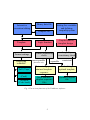
The various functions of TemMaster and their relationship can be seen in Fig. 1
1
This program also serves as a learning aid for chapters 5, 6 and 7 of the lecture notes “Cellular Neural
Networks: Foundations and Primer”, by L. O. Chua and T. Roska, used for the course EE129 at U. C.
Berkeley ( L. O. Chua ) and in a graduate course at the Technical University of Budapest ( T. Roska ).
4
Interactive
generation/editing
Binary data file
Template file
Template
Logic function
Format settings
Linear separability
check
Displaying
truthtable
Full ( Tape )
Minimal
(Card)
Window
(Code book)
non-separable
Setting free variables
and defining
inequalitysystem
Coupled (direct)
template design
Inequality
consistency check
separable
functions only
consistent
Determining quasi
minimal template
sequence
Calculating
optimal template
Quasi minimal
template sequence
files
Optimal template
file
Fig. 1 The various functions of the TemMaster software
5
The main features of the program:
1. There are three possible representations of binary operations given by a CNN template
or given explicitly as a Boolean function:
• The Full Truth-table ( tape ) gives a rigorous description of the CNN’s response to
all possible binary input patterns.
• The Minimal Truth-table ( card ) shows the “fingerprint” of the template ( local rule
and logic function ) at a glance, without carrying all the redundancies of the Full Truthtable ( i.e. not showing the input configurations, the order of outputs is given by the
standard sequence of binary numbers ).
• The Window truth-table ( code book ) shows the actual arrangement of the input
patterns along with the corresponding output, that could be useful when analyzing
binary morphological templates.
2. Linear separability check of explicitly given Boolean functions. If the function is linearly
separable, it can be represented by a single uncoupled CNN template, otherwise see 4.
3. Template optimization. Templates are optimized with respect to their robustness. The
resulting template is optimal in the sense that it represents a hyper-plane which separates all
TRUE vertices from FALSE vertices, whose distance is maximized to the closest vertices
belonging to different groups.
4. Determining a quasi minimal linear decomposition of linearly non-separable logic functions
into a series of separable functions and generating the corresponding sequence of
uncoupled templates.
5. Advanced design of optimal templates by direct definition of an inequality system. This
includes the coupled class of CNN templates in some well defined cases.
Some functions of the program are listed briefly:
• Loading and editing templates
• Loading and editing logic functions
• Defining logic functions via easy-to-use graphical interface
• Three different display modes: two different color formats and a monochrome symbol
format.
• The freedom of modifying the order of binary variables to generate truth tables
• Automatic generation of Visual Mouse and SimCNN compatible script files for easy testing
of the resulting optimal templates and template sequences.
6
2. System Requirements, Installation, Start-up Program
The program requires a computer running Windows 95 operating system, and should be
equipped with a monitor capable of resolution 1024 x 768. The program is shipped with the
CANDY program package and installed automatically, when running CANDY setup, into the
following directory: C:\CANDY\TEMMAST. The installation disk contains the executable code
file WLR32.EXE, the optimization algorithm’s executables, ( PLANECOM3.EXE , and
PLANECMD.EXE ). After proper installation the program can be started by running
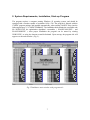
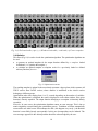
WLR32.EXE, or using the shortcut created beforehand. Upon start-up, the program title will
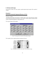
appear over the main window ( Fig. 2 ).
Fig.2 TemMaster main window with program title
7
3. Menu Structure of TemMaster
The basic structure of TemMaster’s menus will be explained in detail in the following sections.
3.1 File menu
Fig. 3 File menu
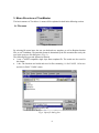
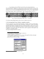
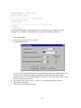
By selecting file menu items, the user can load and save template, as well as Boolean function
files, or exit TemMaster. The particular format is determined by the file extension filter set by the
user in the open-save file dialog box ( Fig. 4 ).
The following file types and formats are allowed:
• *.tem : CANDY compatible single layer linear template file. The results are also saved in
this format.
• *.dat.: The functions are loaded and saved in files containing -1.0 for FALSE, 1.0 for true
and 0.0 for DON’T CARE values.
Fig 4. Open file dialog box
8
The Save sequence item should be selected to save the template sequence generated by one of
the decomposition algorithms. In this case, the file name must have the following format: <group
name ><index of the first template in the group>.tem. E.g. if XOR1 is given the series will be
saved as XOR01.tem, XOR02.tem, …, XOR09.tem. If the initial index is omitted, indices will
start from 1 ( XOR01.tem ).
3.2 Edit menu
At the Edit menu, Fig. 5 the previously loaded template can be edited using an external text
editor ( notepad ), or an arbitrary Boolean function up to nine variables can be defined using a
built-in graphical user interface.
Fig. 5 Edit menu
After setting the number of variables and the arrangement of inputs in the Format menu ( see
section 3.5 ), and activating Function menu item at the Edit menu, the proper number ( 2N ,
where N is the number of variables ) of boxes appears displaying the inputs and the
corresponding output values ( initially, all outputs are set to DON’T CARE, unless a previously
saved function is loaded into the program ).
3.2.1 Graphical Boolean function editor
The graphical function editor can be used to define arbitrary Boolean functions. The function to
be edited is displayed in Window truth-table format. The initial layout follows the settings of the
Format menu. The editor displays inputs and the corresponding outputs in a compact format (
Fig. 6 ).
Index of input
3
Input pixels
Don’t care positions
Output value
9
Fig. 6 Single cell of the Window truth-table used in function definition
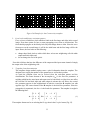
The whole function is displayed as a series of boxes, each in the format shown in Fig. 6. The
frame color of a box ( and the corresponding Boolean function value ) can be set by positioning
the mouse cursor over box and clicking the left mouse button. The frame color changes between
black, white and blue ( TRUE, FALSE, DON’T CARE ) using the default color ( Fig. 7 ).
Fig. 7 Layout of the function editor for N = 5 variables
To edit a previously defined function, select Continue, otherwise select New.
3.2.2 Generating SimCNN and VisMouse compatible script files
In order to apply the newly generated optimal template or template sequence to an input image,
a script file should be written for the actual CNN simulator. TemMaster is capable of generating
SimCNN and VisMouse2 compatible script files. To enable this feature, select Create script in
Edit menu. This menu item is disabled if no template or sequence has been loaded or generated
beforehand. On the other hand, this feature can be used to generate VM script for any
CANDY [5] compatible template.
The steps of script generation are as follows:
Creating script for optimal template:
1. Load template to be optimized ( example: corner.tem )
2. Optimize template ( see section 3.4 )
3. Set the template saving path in Directories menu. The script file will refer to this path.
Save optimized template ( example: o_corner.tem ).
4. Select Create script in Edit menu.
2
SimCNN and VisMouse are part of the CANDY system.
10
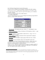
In the VM Script Setting dialog box set the following items:
Script File Name: Arbitrary ( max. 20 characters ) file name with “dde” extension.
Template/Group Name: Template name without extension as saved in step 3 above.
Note, that with proper settings script can be generated for arbitrary ( non TemMaster
generated ) templates.
Script Path: Script file location. The CANDY default is:
C:\CANDY\COMMUNIC
Advanced: In the Advanced Script Settings dialog box the following script parameters
can be set ( with the default values shown ):
Time step (∆t): CNN simulation time step ( default: 1.0 3 ( see footnote! ), range:
0< ∆t ≤ 1.0 )
Number of iterations ( n ): Number of iterations in CNN simulation ( default: 1, range:
1≤ n ≤ 999 )
Boundary: Boundary in CNN simulation ( default: fixed to -1, range: -10.0 ≤ n ≤
10.0, or zeroflux or periodic )
Output sampling (o): Number of iterations after the output transient is displayed
( default: 1 , range: 1≤ o ≤ n )
Same State: In case of templates requiring images loaded to the state. ( default:
unchecked )
Intermediate: In case of template sequences, the intermediate results can be
displayed after each logic operation enabling this checkbox. ( default: unchecked )
Remarks on advanced settings: Default settings can be used for all TemMaster
generated uncoupled templates or template sequences.
Number of cycles: If this value is greater than one, the output of a template operation is
reloaded to the input, and the template is applied to this image again. It has significance,
only if the template operation introduces spatial shift.
3
Although the default value of 1.0 is not correct for the faithful discrete simulation of an arbitrary CNN
transient, it provides equivalent results for uncoupled binary operations, while having short simulation time.
If we are interested in transient results of shorter interval or when using propagating templates, this value
must be set much lower ( e.g. 0.1 ).
11
Example script for optimal corner template:
%********************************************************************
%***************** VM Script Generated by TemMaster ***************
%********************************************************************
{ Start : Corner }
Initialize SimCNN CSD
%************************************* General Settings
TemplatePath C:\CANDY\TEMLIB
WinLayout 3
AssignWinPart 1 INPUT
AssignWinPart 2 OUTPUT
AssignWinPart 3 LLM[2]
TimeStep 1.0
IterNum 1
SendTo INPUT
%************************************* Start Loop
%************************ Cycle 1
%**************** Sequence Item 1
PicFill STATE 0.0
TemLoad Corner.tem
RunTem
Display OUTPUT
%************************ Cycle 2
%**************** Sequence Item 1
PicFill STATE 0.0
TemLoad Corner.tem
RunTem
Display OUTPUT
%************************************* End of Loop
Terminate
{ STOP: Corner }
12
Creating script for template sequence:
1. Load or define a non-separable function ( example: Glife.dat ).
2. Generate template sequence ( see section 3.4 ).
3. Set the template saving path in Directories menu. The script file will refer to this path.
Save sequence as shown in section 3.1 ( example: glife01.tem, glife02.tem ).
4. Select Create script in Edit menu.
In the VM Script Setting dialog set the following items:
Script File Name: Arbitrary ( max. 20 characters ) file name with “dde” extension.
Template/Group Name: template group name without extension and index, as saved in
step 3. Note, that with proper settings, script can be generated for arbitrary TemMaster
compliant sequence.
Script Path: Script file location. The CANDY default is: C:\CANDY\COMMUNIC , it
can also be set in the Directories menu.
Advanced: See earlier in this section.
Number of cycles: If this value is greater than one, the output of a the template sequence
operation is reloaded to the input, and the template is applied to this image again. It has
significance, only if the operation introduces spatial shift. ( example: 2 ).
13
Example script for template sequence implementing the game of life:
%********************************************************************
%***************** VM Script Generated by TemMaster ***************
%********************************************************************
{ Start : Glife }
Initialize SimCNN CSD
%************************************* General Settings
TemplatePath C:\CANDY\TEMLIB
WinLayout 3
AssignWinPart 1 INPUT
AssignWinPart 2 OUTPUT
AssignWinPart 3 LLM[2]
TimeStep 1.0
IterNum 1
SendTo INPUT
%************************************* Start Loop
%************************ Cycle 1
%**************** Sequence Item 1
PicFill STATE 0.0
TemLoad glife01.tem
RunTem
Display OUTPUT
PicCopy OUTPUT LLM[1]
%**************** Sequence Item 2
PicFill STATE 0.0
TemLoad glife02.tem
RunTem
Display OUTPUT
RunLog XOR LLM[1] OUTPUT LLM[2]
Display LLM[2]
PicCopy LLM[2] LLM[1]
%************************ Update Input
PicCopy LLM[2] INPUT
Display INPUT
%************************ Cycle 2
%**************** Sequence Item 1
PicFill STATE 0.0
TemLoad glife01.tem
RunTem
Display OUTPUT
PicCopy OUTPUT LLM[1]
%**************** Sequence Item 2
PicFill STATE 0.0
TemLoad glife02.tem
RunTem
Display OUTPUT
14
RunLog XOR LLM[1] OUTPUT LLM[2]
Display LLM[2]
PicCopy LLM[2] LLM[1]
%************************ Update Input
PicCopy LLM[2] INPUT
Display INPUT
%************************************* End of Loop
Terminate
{ STOP: Glife }
For a detailed description of running script files see VisMouse User’s Guide [11], and
SimCNN User’s Guide [12]. The following is an example for running Glife.dde:
1. Start Visual Mouse
2. Select Script Settings in Options menu
3. Set the following items:
remarks: The communication block name should be the same as the script file name. The
script opens two additional windows to display operands of the consecutive logic
operations ( in case of a template sequence ). Number of Windows and Idle Time values
have no significance in our case.
4. Set “Specified in script settings” at Select script submenu of SimCNN menu.
5. Open a binary image file.
6. Select Run script at SimCNN menu.
15
3.3 Display
The output of the actual template, and a Boolean function previously loaded or defined can be
visualized in three different formats: Minimal truth-table, Full truth-table, and Window truthtable.
Fig. 8 Display menu.
A brief description of these formats:
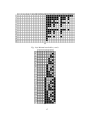
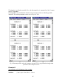
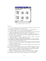
1.Minimal truth table (Fig. 9a): Single table containing all outputs for all possible input
combinations. Since the output is generated for consecutive binary codes of ascending order,
it is not necessary to display these input combinations, thus eliminating the redundancies. The
index of an arbitrary output value is given by output index = ( row index -1 )* 32 + column
index.
2.Full truth table (Fig. 9b): Up to 16 tables containing all the binary input codes and the
outputs for these inputs. Maximum four tables are displayed at a time. One can move between
screens by clicking on forward and rewind buttons using the left mouse button.
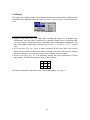
3.Window truth-table (Fig. 9c): Full truth-table showing the actual arrangements of binary
input patterns. The default arrangement of the 9 input variables:
9
6
3
8
5
2
7
4
1
The output is displayed as the frame of the corresponding pattern ( see Fig. 6).
16
(a)
Fig. 9 (a) Minimal truth-table ( card )
(b)
17
(c)
Fig. 9 (b) Full truth-table ( tape ), (c) Window truth-table ( code book ) of Corner template
3.4 Optimize
This menu (Fig. 10) is used to invoke the optimization algorithm. The optimization algorithm can
be used
• to generate an optimal template for the output function defined by a template loaded
beforehand ( i.e. optimize the template ),
• to calculate an optimal template or template series for a previously loaded or defined
arbitrary Boolean function .
Fig. 10 Optimization menu
The resulting template is optimal in the sense that it represents a hyper-plane which separates all
TRUE vertices from FALSE vertices, whose distance is maximized to the closest vertices
belonging to different groups.
Optimization takes time ranging from 1 to 15 seconds depending on the number of variables.
When the optimization is completed, the result is displayed in a text editor window, if the given
function is linearly separable. The output function belonging to a template is inherently linearly
separable.
Remarks: In some cases, the optimization algorithm returns an error message. This is due to
matrix singularity occurred during the optimization process. TemMaster will then automatically
restart with a new initial vector. If this attempt also fails ( this happens very rarely ), the Boolean
function is most likely linearly non-separable. In this case decomposition can be initiated. The
error message appeared in the desktop taskbar should be acknowledged by the user.
18
In the case of arbitrary Boolean functions, the vast majority is non-separable. In this case a
decomposition algorithm can be applied, which derives a quasi minimal set of templates that
implements the function in question. The user can choose between two different algorithms.
While the compact algorithm generates shorter sequences in most of the cases, the CFC
algorithm creates somewhat more robust templates. With the selection of Advanced compact
checkbox (Fig. 11), additional linear separability check can be added to the compact algorithm
after each iteration. This results in slower execution but in some cases shorter sequences
Fig 11. Decomposition methods dialog box
3.5 Format
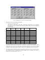
The Format dialog box, appearing after the activation of Format menu, is used to set the
following parameters:
•
•
•
•
•
Input format. The order of binary values arranged in a 3-by-3 window as it is loaded to
the CNN input. Different orders can be defined for templates and functions. The initial
setting for both follows a Default pattern ( see Fig. 12 ). The default pattern can also be
modified. In the case of Boolean functions, the number of input variables can be determined
by setting certain positions to 0. The number of input variables for templates is determined
automatically upon loading.
Initial state of the CNN can be set in the [-100.0, 100.0] range. Alternatively, “same”
can be given entered in this edit box, in which case the output for the template is calculated,
as if the same patterns were loaded to the state and the input. The default value of the initial
state is 0.0.
The maximum value of the optimal templates can be set. If the string“arbitrary” is given,
the optimal templates appear as they are calculated by the optimization algorithm. The
default is “arbitrary”. Max. value is important in the case of circuit design, where the range
of possible values is limited.
The color format of the truth tables. Color 1 ( default ) means TRUE - black, FALSE white, and DON’T CARE - blue; Color 2 means TRUE - red, FALSE - blue, and DON’T
CARE - white; the Monochrome format is the same as Color 1 except the DON’T CARE
values are gray.
Don’t cares. In order to calculate optimal template for a function loaded previously or
defined at the Edit menu, all function values have to be set to either TRUE or FALSE. Since
19
it is allowed to leave certain values of the function as DON’T CAREs during the definition
phase, we have to set a definite value during optimization. At this menu the DON’T CAREs
can be set to TRUE or FALSE or leave it As it is, albeit in this case the optimization cannot
be started.
Fig. 12 Format settings dialog box
3.6 Coupled
The program provides a graphical interface to design templates ( including coupled templates )
implementing binary operations.
Exploiting the a priori knowledge about the template’s format, up to four variables ( and their
opposite (-) ) can be positioned accordingly. If the template has more entries, more than one of
these have to have similar function, thus they can be denoted by a single common variable.
These are the so called symmetric variables ( not to be confused with template symmetry! ).
Symmetric operations have the special property of being invariant to the permutation of the input
entries. The degree of symmetry can be different depending on the group of variables to which
the function is symmetric. The Direct method published in [8] provides a straightforward way
to design templates implementing these functions. This method also allows us to design coupled
templates in some special cases.
Upon invoking this menu item the Template format settings dialog box appears, where the
user can enter the number and position of symmetric variables using scroll boxes. Don’t care
positions should be set to 0.
20
Fig.13 Template format settings for coupled templates dialog box
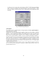
After the parameter selection the whole set of inequalities is generated by the program and
displayed in a format seen in Fig. 14. The user can modify the inequalities according to the
particular design problem by clicking on the desired row of the table using the left mouse button.
Note, that the CNN’s bias ( denoted by i ) is a free parameter by default! The inequality
system can then be submitted to optimization at the Evaluate sub-menu of Coupled menu. If
the inequality set is consistent, the optimization results in an optimal template displayed in a text
editor window at the end of the optimization.
The format of the table of inequalities can be seen in Fig. 14. In addition to the inequalities, it
also contains the possible values of the free parameters ( left ), the output values y, and index
( right ). If the particular parameter is single ( there is only one of it ), its two possible values are
displayed graphically. Otherwise, the possible number of true ( matching ) pixels is given.
21
Fig. 14 Inequality system generated for the direct design method of variables seen in
Fig. 13
4 File formats
The program can load CANDY compatible single-layer linear template files. The results are
also saved in this format. For sequence formats see section 3.1. The functions are loaded and
saved in files with *.dat extension containing -1.0 for FALSE, 1.0 for TRUE and 0.0 for
DON’T CARE values.
22
5. Getting started
In the following, some examples will be discussed starting with simpler ones and advancing to
more complicated ones. The examples introduce the basic steps of uncoupled template design
and optimization
Example I
Logic function definition of Horizontal Line detection:
For simplicity we consider all input patterns a horizontal line if the central pixel is TRUE and has
at least one TRUE horizontal neighbor. Note, that according to the definition, only three
positions must be considered, therefore the rest can be set to DONT CARE.
1. Select Format at the main menu
2. Set input pattern for function according to Fig. 16.
3. Choose the Function sub-menu at Edit and set the values shown in Fig. 17.
Fig. 16 Input arrangement of horizontal line detection
Fig 17 Layout of the definition of Horizontal Line Detection
23
The size and number of the Window tables necessary to describe the logic function is
determined according to the active variables in the input pattern. ( e.g. for horizontal line
detection, only three variables are active, therefore the size of the table is 23 = 1x8 cells )
24
Example II
Calculating Optimal Template for Horizontal Line Detection
Input and desired output of the Horizontal Line Detection ( HLD ) :
Input of the optimization algorithm:
Boolean function of HLD
Output:
Parameters of the optimal separating hyper-plane: a1 x1+ a2 x2+ a3 x3 + b = 0, where a = [a1,
a2, a3] is the normal vector of the plane, b is constant threshold. The resulting template is
expected in the format:
0
A= 0
0
0
1
0
0
0
0
B=
0.0
a1
0.0
0.0
a2
0.0
0.0
a3
0.0
z= b
In general, the elements of
the normal vector are entries of template B, and the threshold is the CNN’s bias.
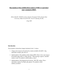
Fig 17 Boolean function of Horizontal Line Detection ( HLD ) and the hyper-cube’s
intersection with the separating hyper-plane
The plane is optimal in the sense that the distance between the separating hyper-plane and the
closest vertex is maximized.
The optimal parameters calculated by our algorithm:
a1 = 1.0
a2 = 2.0
a3 = 1.0
25
b = -1.0
The corresponding template:
0
A= 0
0
0
1
0
0
0
0
B=
0.0
1.0
0.0
0.0
2.0
0.0
0.0
1.0
0.0
z = -1.0
Fig. 18 Output of optimization of Horizontal Line Detection
Example III
Linear decomposition of the ‘Game of Life’ function
This example comes from the world of Cellular Automata. The rules of the game:
• A black pixel turns white if it has more than three or less than two black neighbors.
• A white pixel turns black if it has exactly three black neighbors.
Fig. 18 Minimal truth table for the Game of Life:
26
The function is not linearly separable. Now the decomposition is attempted by both Compact
and CFC algorithms.
Both algorithms have found that the function can be decomposed into two linearly separable
functions. The resulting templates can be seen in Fig. 19a - 19b.
(a)
(b)
Fig 19 Decomposition results by Compact (a) and CFC (b) algorithm. Both algorithm
found the same template values.
Example IV
Decomposition of XOR function of nine variables.
Definition:
f ( x ) = (((( x1 ⊗ x 2 ) ⊗ x3 )... ) ⊗ x 9 )
27
The results are shown in Fig. 20
B1=
1 -1 -1
-1 -1 -1
-1 -1 -1
B2=
-1 1 1
1 1 1
1 1 1
A 2=
0 0 0
0 1 0
0 0 0
B3 =
1 -1 -1
-1 -1 -1
-1 -1 -1
A 3=
0 0 0
0 1 0
0 0 0
z3=
-2
B4=
-1 1 1
1 1 1
1 1 1
A4 =
0 0 0
0 1 0
0 0 0
z 4=
-4
B 5=
1 -1 -1
-1 -1 -1
-1 -1 -1
A5=
0 0 0
0 1 0
0 0 0
z5 =
-4
B 6=
-1 1 1
1 1 1
1 1 1
A6=
0 0 0
0 1 0
0 0 0
z6 =
-6
B 7=
1 -1 -1
-1 -1 -1
-1 -1 -1
A7=
0 0 0
0 1 0
0 0 0
z7 =
-6
B 8=
-1 1 1
1 1 1
1 1 1
A8=
0 0 0
0 1 0
0 0 0
z8 =
-8
B 9=
1 -1 -1
-1 -1 -1
-1 -1 -1
A9=
0 0 0
0 1 0
0 0 0
z9 =
-8
A 1=
0 0 0
0 1 0
0 0 0
z 1=
0
z 2=
-2
Definition:
f ( x ) = (((( x1 ⊗ x 2 ) ⊗ x3 )... ) ⊗ x9 )
Compact decomposition
Calculating optimal templates
28
Fig. 20 Decomposition of XOR of nine variables defined by
f ( x ) = (((( x1 ⊗ x 2 ) ⊗ x3 )... ) ⊗ x 9 )
29
6. Advanced design
In this section a simple, and a more complex coupled template design example will be explained
in detail.
Example V
Horizontal Connected Component Detector ( CCD )
The task is as follows:
In steady state, the output of each image row should contain as many single black pixels starting
from the right end separated by white pixels, as the number of white separated continuous black
sections ( connected components ) in the particular row.
The expected format of the template:
Fig. 21 Settings for horizontal CCD template design
The inequality system complying with the description of the task:
Fig. 22 Inequality system for horizontal CCD template design
30
Choose Evaluate in the Coupled menu. The resulting CCD template:
31
Fig. 23 Optimal horizontal CCD template
Example VI
Connectivity
The task is as follows:
Two binary images are given. The first contains some black objects against white
background. The second is derived from the first one by changing some black pixels to
white. This way some objects become smaller in the second image than in the first. Those
objects, which have become smaller in the second image are considered to be marked. The
task is to design a template, which deletes the marked objects and do not affect the rest of
the image. If we delete a single pixel of a black object and apply this template, all the black
pixels connected to the object will turn white. Hence this template is called Connectivity in
the Template Library.
1.
Global rule
This is a 2D problem. All connected black pixels of the marked objects should change
white, and the rest of the pixels should be unchanged. An example can be seen in Figure
24.
32
First image
Second image
Final output
Figure 24 Example for the Connectivity template.
2.
Local rules and binary activation pattern
First, we have to find those pixels which are black in the first image and white in the second
image. From these points we have to start propagating wave fronts to all directions. The
front should propagate on the black pixels only and change them to white. Since the wave
front moves on the second image, it will be the initial state and the first image will be the
input. Hence, the local rules are the following:
•
•
change those black pixels to white which have at least one neighboring cell with white
output and black input, and
do not change the rest of the pixels.
From this it follows that here the difference of the output and the input counts instead of simply
the output value of the neighboring cells.
3.
Template form determination
This template design method requires some a priori information about the template. The
designer has to supply the number of free parameters as well as their position.
As usual the template form can be derived from the activation pattern and the
classifications. The center element of the A template (a00 ) is the first free parameter. A
neighbor which has the same input and output (can be both black or white) does not affect
the cell. But if it has black input and white output it activates the cell. Hence, the second
free parameter appears in the neighborhood in both the A and the B template, but with
opposite sign. The center element of the B template is the third free parameter. Since the
propagation is asymmetric, the bias z is the fourth free parameter. The template is sought in
the following form:
0 b 0
A = b a b, B =
0 b 0
0 −b 0
− b c − b, z = i
0 − b 0
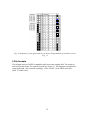
The template format can be set selecting the Design item in the Coupled menu (Fig. 25).
33
(1)
Fig. 25 Settings for Connectivity template design
Remember, bias is a free parameter by default!
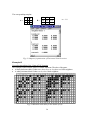
4.
Inequality system generation
Since there are only three valid binary input-output combinations and 5 matching
possibilities, there are 15 different cases. Each case yields a relation. The set of inequalities
is the following:
output
dependency
black (+1)
black (+1)
black (+1)
black (+1)
black (+1)
white (-1)
white (-1)
white (-1)
white (-1)
white (-1)
white (-1)
white (-1)
white (-1)
white (-1)
white (-1)
input
dependency
black (+1)
black (+1)
black (+1)
black (+1)
black (+1)
black (+1)
black (+1)
black (+1)
black (+1)
black (+1)
white (-1)
white (-1)
white (-1)
white (-1)
white (-1)
# of different
pixels
0
1
2
3
4
0
1
2
3
4
0
1
2
3
4
dynamics
desired output
relation
active
inactive
inactive
inactive
inactive
inactive
inactive
inactive
inactive
inactive
inactive
inactive
inactive
inactive
inactive
black (+1)
white (-1)
white (-1)
white (-1)
white (-1)
white (-1)
white (-1)
white (-1)
white (-1)
white (-1)
white (-1)
white (-1)
white (-1)
white (-1)
white (-1)
a+c+i>1
a-2b+c+i<1
a-4b+c+i<1
a-6b+c+i<1
a-8b+c+i<1
-a+c+i<-1
-a-2b+c+i<-1
-a-4b+c+i<-1
-a-6b+c+i<-1
-a-8b+c+i<-1
-a-c+i<-1
-a-2b-c-i<-1
-a-4b-c+i<-1
-a-6b-c+i<-1
-a-8b-c+i<-1
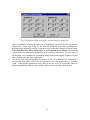
This table contains only the relevant cases. TemMaster generates the inequality system
automatically and it contains all possible cases. The invalid inequalities can be omitted by simply
setting the corresponding outputs to DON’T CARE. The resulting table can be seen in Fig. 26.
The optimal coupled template can then be generated by activating Evaluate menu item. Since
the inequality system is consistent, the optimal template can be calculated. The result is
displayed in a text editor window ( Fig. 27 ).
34
Fig. 26 Inequality system for Connectivity template design
35
Fig. 27 Optimal Connectivity template
References:
[1] L. O. Chua, T. Roska: Cellular Neural Networks: Foundations and Primer Lecture
notes for the course EE129 at U. C. Berkeley 1996-97
[2] L. O. Chua, L. Yang: Cellular Neural Networks: Theory , IEEE Transactions on
Circuits and Systems, Vol. 35, No. 10, pp. 1257-1290, October 1988
[3] L. O. Chua , T. Roska: The CNN Paradigm, IEEE Transactions on Circuits and SystemsI: Analog and Digital Signal Processing, Vol. 40, pp. 147-156, March 1993
[4] T. Roska, L. O. Chua: The CNN Universal Machine: An Analogic Array Computer,
IEEE Transactions on Circuits and Systems-II: Analog and Digital Signal Processing, Vol.
40, No. 3, pp. 163-173, March 1993
[5] Cs. Márton, I. Szatmári, K. László, Cs. Rekeczky, L. Nemes, T. Roska, P. Szolgay, Á.
Zarándy: CADETWin User’s Manual MTA SzTAKI 1997
[6] K.N Crounse, E.L. Fung, L.O. Chua: Efficient Implementation of Neighborhood Logic
for Cellular Neural Automata via the Cellular Neural Network Universal Machine,
IEEE Transactions of Circuits and Systems, 1996
[7] L. Nemes, L. O. Chua, T. Roska: Implementation of Linearly Non-separable Boolean
Functions on the CNN Universal Machine, paper submitted to the CTA special issue
on CNN, to be published in 1998
[8] Á. Zarándy: The Art of CNN Template Design, paper submitted to the CTA special issue
on CNN, to be published in 1998
[9] L. O. Chua: CNN: Paradigm for Complexity, Int. J. of Bifurcation and Chaos, Aug. 1997
[10] CNN Software Library (Templates and Algorithms) Version 7.2, Edited by T. Roska,
L. Kék, L. Nemes, Á. Zarándy, P. Szolgay, and M. Brendel, Computer and Automation
Institute of the Hungarian Academy of Sciences, Budapest, 1998.
[11] Cs. Márton, I. Szatmári, K. László, Cs. Rekeczky, T. Roska, P. Szolgay, Á. Zarándy:
VisMouse - CNN Visual Mouse Platform for Windows, Program Logic Manual
[12] István Szatmári: SimCNN - Multi-layer CNN Simulator Server, User’s Guide
36