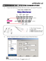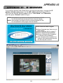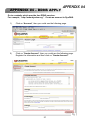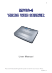
1
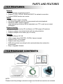
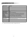
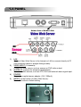
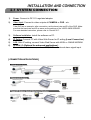
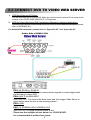
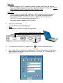
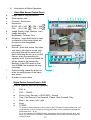
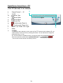
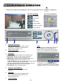
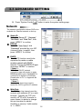
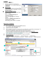
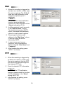
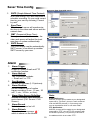
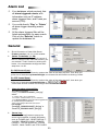
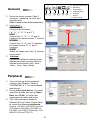
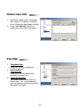
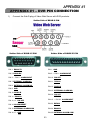
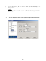
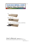
25 Video Web Server 2CH MJPEG VIDEO WEB SERVER User’s Manual Please read instructions thoroughly before operation and retain it for future reference. CPN103_V1.1 Thank-You Note Before You Get Start First of all, we would like to express our gratitude to you for purchasing this product. This product is designed to meet your personal needs with our great industry-designing ability and our everlasting perseverance to the quality of all our products. This manual will introduce to you how to install this apparatus. Please keep it well for your future reference. Now, we would like to invite you to personally experience all of the powerful functions this product offers. Note: Firmware: Kernel: 1.0.1.0 AP application: 1.0.4.3 Note: Any changes of the AP application, please refer to your distributor. Note: Any changes of this manual made to the actual product are subjects to no further notification. IMPORTANT SAFEGUARD CAUTION RISK OF ELECTRIC SHOCK DO NO OPEN CAUTION: To reduce the risk of electric shock, do not expose this apparatus to rain or moisture. Only operate this apparatus from the type of power source indicated on the label. The company shall not be liable for any damages arising out of any improper use, even if we have been advised of the possibility of such damages. The lightning flash with arrowhead symbol, within an equilateral triangle, is intended to alert the user to the presence of uninsulated “dangerous voltage” within the product’s enclosure that may be of sufficient magnitude to constitute a risk of electric shock to persons. This exclamation point within an equilateral triangle is intended to alert the user to the presence of important operating and maintenance (servicing) instructions in the literature accompanying the appliance. CE Mark This apparatus is manufactured to comply with the radio interference requirements. The company does not warrant that this manual will be uninterrupted or error-free. We reserve the right to revise or remove any content in this manual at any time. TABLE OF CONTENTS PARTS AND FEATURES 1.1 1.2 1.3 1.4 FEATURES -----------------------------------------------------------------------------------------------------------PACKAGE CONTENTS -------------------------------------------------------------------------------------------SPECIFICATION ----------------------------------------------------------------------------------------------------PANEL ------------------------------------------------------------------------------------------------------------------ 1 1 2 3 INSTALLATION AND CONNECTION 2.1 2.2 2.3 2.4 2.5 SYSTEM CONNECTION ------------------------------------------------------------------------------------------CONNECT DVR TO VIDEO WEB SERVER -----------------------------------------------------------------SOFTWARE INSTALLATION -----------------------------------------------------------------------------------IP SETTING AND LAN CONNECTION -----------------------------------------------------------------------CONNECT VIA INTERNET --------------------------------------------------------------------------------------- 4 5 6 6 11 OPERATION GUIDE 3.1 SOFTWARE OPERATION ----------------------------------------------------------------------------------------3.2 PLAYBACK OPERATION ----------------------------------------------------------------------------------------3.3 ADVANCED SETTING ---------------------------------------------------------------------------------------------Network -----------------------------------------------------------------------------------------------------------DDNS --------------------------------------------------------------------------------------------------------------Mail ----------------------------------------------------------------------------------------------------------------FTP -----------------------------------------------------------------------------------------------------------------Server Time Config --------------------------------------------------------------------------------------------Alarm ---------------------------------------------------------------------------------------------------------------Alarm List ---------------------------------------------------------------------------------------------------------General ------------------------------------------------------------------------------------------------------------Account -----------------------------------------------------------------------------------------------------------Peripheral ---------------------------------------------------------------------------------------------------------Online User Info ------------------------------------------------------------------------------------------------File Path ------------------------------------------------------------------------------------------------------------ 12 15 16 16 17 18 18 19 19 20 20 21 21 22 22 APPENDIX #1 APPENDIX #2 APPENDIX #3 APPENDIX #4 27 DVR PIN CONNECTION ------------------------------------------------------------- 23 PTZ PIN CONNECTION -------------------------------------------------------------- 25 IE BROWSER -------------------------------------------------------------------------- 26 DDNS APPLY -------------------------------------------------------------------------- 1.1 FEATURES PARTS AND FEATURES Network: JPEG real time compression format Support TCP/IP, PPPoE, DDNS and DHCP for network connection Support DDNS function as a router Alarm: Support alarm trigger recording Full alarm-triggered event list for easy search and quick playback Whenever alarm system triggered, video streaming or pictures will be uploaded over FTP, email as an instant notification. Network Viewing: Support video access by APs (software) or HTML pages (IE explorer) Support multiple user access levels with security protection Support multiple on-line users (up to 5 users) General: Support different PC OS Video output: Up to 30(NTSC), 25(PAL) frames/ second Support NTSC / PAL system Support watch dog function ANR will reactivate recording function automatically when network is reconnected Easy to upgrade firmware 1.2 PACKAGE CONTENTS Video Web Server Licensed Software AP Manual & Quick Start Crossover Cable Adapter NOTE : Please check the package contents to make sure that all accessories are included. 1 1.3 SPECIFICATION Specification CPN103 Video Input 2 channel for analog & digital products, 1.0 Vp-p 75 composite, BNC Alarm Input 4 inputs / 2 outputs Watch dog Yes RS-485 Port Yes Network Interface Ethernet (10/100 Base-T) Image Compression JPEG Video Adjustment Brightness, Contrast and Hue Network Connection Support TCP/IP, PPPoE, DDNS and DHCP for network connection Protocols TCP/IP, ICMP, SMTP, FTP, HTTP, DHCP, DDNS, PPPoE, SNTP Resolution 704x480, 352x240 (NTSC) / 704x576, 352x288 (PAL) Performance Video output: Up to 30(NTSC), 25(PAL) frames/ second Alarm Trigger Recording Yes Trigger & Action Triggered by GPIO Input, Action: E-mail video/images or video/images upload to FTP site's specific accounts Security Password Protection Power Source DC 12V Current consumption 500 mA Design and specification are subject to change without notice. 2 1.4 PANEL Solder Side of DSUB 9 PIN NO COM 1) 2) 3) 4) 5) LAN: Connect Video Web Server to the Internet or LAN or connect directly to PC (Use crossover cable or straight-through cable). VIDEO INPUT (2 channels): Connect to video source, such as camera or DVR video output. ALARM I/O (optional for advanced applications): Connect control devices, such as PTZ, DVR and external alarm signal input. POWER: Plug in the supplied power adaptor (12V / 500mA). RESET (at the bottom of Video Web Server): Press this button to default setting. 3 INSTALLATION AND CONNECTION 2.1 SYSTEM CONNECTION 1) Power: Connect to DC 12V regulated adapter. 2) Video Input: Connect to video outputs of CAMERA or DVR…etc. Take DVR as an example, after connection, set the baud rate and ID of the DVR. Make sure that the baud rate and ID as same as the settings of the VIDEO WEB SERVER. For more detailed instruction, please refer to “Section 2.2”. 3) Software Installation: Install the software on PC. 4) IP Setting: Connect PC with Video Web Server for IP setting (Local Connection). 5) LAN: After IP setting, connect Video Web Server with ADSL or CABLE MODEM. 6) ALARM I/O (Optional for advanced applications) : Connect to control devices, such as PTZ, DVR and external alarm signal input. [ CONNECTION APPLICATIONS ] 4 2.2 CONNECT DVR TO VIDEO WEB SERVER 1) DVR Baud Rate and ID Setting: Set the baud rate and ID of the DVR. Make sure that the baud rate and ID as same as the settings of the VIDEO WEB SERVER (P.21 Peripheral). 2) DVR and Video Web Server PIN Connections (Optional for advanced application): Connect DVR PIN with VIDEO WEB SERVER PIN (For more detailed information, please refer to APPENDIX #1 ). For detailed PIN connection, please refer to “Appendix #2 ” and “Appendix #3” Solder Side of DSUB 9 PIN PIN 1, 6: RS485-A, RS485-B Use RS485-A & RS485-B serial communication signals to control digital units just like that to control DVR. PIN 4, 9, 8, 7: ALARM INPUT Use PIN 4,,9, 8, 7 to receive the alarm input and then trigger Video Server to send mail to users for auto e-mail warning system. . PIN 5: GND Ground PIN 2, 3: NORMAL HIGH, NORMAL LOW Use PIN 2 or 3 to trigger external device to act. Please see the example picture below for 1CH/4CH DVR. It’s recommended to solder these joints 5 2.3 SOFTWARE INSTALLATION 1) Put the attached CD into a CD-ROM and it will start to install application program into PC. 2) Click “Install Video Server“ to run the setup program. 3) Click “Finish” button to complete the setup. And you will see the icon “ “ on the desktop. Note: After physical connection, please go to the next two sections for IP address settings. 2.4 IP SETTING AND LAN CONNECTION 1) Network setting for PC. (This following instruction is based on Win XP OS. If the O/S is Win 2000, the setup procedure is similar to that on Win XP OS.) Step 1- 1: Start Æ Control Panel Æ Network and Internet Connections Æ Network Connections Æ Local Area Connection Status Æ Properties Æ Internet Protocol (TCP/IP). 6 Step 1- 2: Before changing any PC properties setting, please write down the original network setting in order to recover the original PC network setting after “VIDEO WEB SERVER IP SETTING AND LAN CONNECTION” . Step 1- 3: Click on “Use the following IP address” , set IP address and subnet mask. The IP address should be like 192.168.1.XXX (under the same subnet). The setting of “XXX” could be set from 1 to 255 except 10 ( Because 192.168.1.10 is the video web server default IP ). The subnet mask is always 255.255.255.0. 2) After PC IP SETTING, connect PC with Video Web Server. Server Note: Use crossover cable or straight-through cable. crossover cable or straightstraight-through cable RJRJ-45 POWER 3) To configure the Server IP, please click 4) Key in User Name, Password, and Server IP (The default setting of User Name and Password are admin; Server IP 192.168.1.10, Port : 80 ). Then click the green button to connect. 7 twice to enter the setup. 5) When you see the following screen, means successfully logged in the live viewer of the Video Web Server. Click “System Config” to set up. 6) In the Peripheral setting, set “Baud Rate”, “ID” and “Model” which you want to remote control later. Press “APPLY” to enable the change after the setting. The setting of “Baud Rate” , “ID” should be the same as the setting of the external device you want to remote control. 8 7) Click on the Network, set “Server IP”, “Gateway”, “Net Mask” which are provided from your local ISP ( internet service provider ), “Web Port” and “IP type”. Press “APPLY” to enable the change after the setting. Static IP: Dynamic IP: 8) Note: For dynamic IP (PPPoE, DHCP) circumstances, you need apply “Host Name” Name first. Please refer to “APPENDIX #4 – DDNS APPLY” Disconnect PC and Video Web Server, and then connect Video Web Server to the Internet with RJ-45 (crossover cable of straight-through cable). crossover cable or straightstraight-through cable MODEM RJRJ-45 POWER 9 2.5 CONNECT VIA INTERNET 1) Recover PC network setting to the original setting and link PC to the internet. ( Since the PC IP setting has been changed, now it must recover to the original setting for connecting to internet ). 2) Click twice and enter “User Name”, “Password”, “Static IP” and “Port”. Then click the green button to connect. NOTE : The default username and password are both “admin”. Static IP: User Name Password Static IP Address Port Number Dynamic IP: User Name Password DDNS Host Name Port Number 11 OPERATION GUIDE 3.1 SOFTWARE OPERATION After physical connection and network setting of the video web server. Please following the illustrations in this section for software operation. 1) Click twice to enter Login page. 2) Key in “User Name”, “ Password”, and “Server IP” (Static IP) or “Host name”(Dynamic IP). Click the green button to connect. 3) LOGIN AP Icon Explanation: Address Book: Press this button to add frequently-used IP address or choose any preset IP address to access the Video Server. Copy: Press this button to copy all the software installation files, so you could keep all the settings of video web server for next software installation on other PC. Search: Search available IP address of the external device in local area. And modify the network settings of the external device. Upgrade Firmware: Press this button to upgrade firmware. The provided firmware files should be saved at PC first. Player: Press this button to access and play the recorded files saved in the PC. 12 4) Introduction of Basic Operation: Video Web Server Control Panel a. b. c. d. e. f. g. h. i. j. Image transfer rate per second Data transfer rate Connect / Disconnect Resolution: NTSC: 352 × 240 ; 704 × 480 PAL: 352 × 288 ; 704 × 576 Image Quality (High, Medium, Low) Image Adjusting : Brightness / Contrast/ Hue Snapshot : press this button to have a snapshot of the image which will be saved in the designated destination. Record : press this button, the video web server will start to record, and recording files will be saved to PC. Each recording file can up to 18,000 frames, when the recording file capacity is full, the new recorded file will be saved to the second file. Besides, if the HDD space is less than 200MB, the program will stop recording. System config: press this button to enter the setting page of the video web server. Number of online users a b c d e f g h i q. p. m n. k. l. o. Digital Device Control Panel ~ DVR (Take 4 channel DVR for an example) k. l. m. n. o. p. q. CH1-4 PIP/+, QUAD/- Zoom, Lock, Record ( in DVR HDD ), Search Stop, Fast Rewind, Fast Forward , Pause, Slow Forward, Play Menu / up / down / left / right Enter TURBO: To speed up menu selection or the control of the PTZ camera under software AP, you could activate "Turbo" function by clicking this button. You are allowed to change the turbo steps from 1 to 30. . Ex. If you activate the TURBO function, and set the value of the turbo step as 3, then when you press one of the button up/down/left/right, one mouse click will function as clicking 3 times. 13 j Digital Device Control Panel ~ PTZ (Take PTZ (Normal) for an example) k. l. m. n. o. p. q. r. s. t. u. k. Preset Points 1 ~ 16 AUTO Zoom Tele Zoom Wide Focus Near Focus Far Continuously Zoom In Continuously Zoom Out Menu / up / down / left / right Enter TURBO: l. m. n. o. p. q. r. t. u. s. To speed up menu selection or the control of the PTZ camera under software AP, you could activate "Turbo" function by clicking this button. You are allowed to change the turbo steps from 1 to 30. Ex. If you activate the TURBO function, and set the value of the turbo step as 3, then when you press one of the button up/down/left/right or “ “ , one mouse click will function as clicking 3 times. 14 3.2 PLAYBACK OPERATION Please find a manual recorded file in the PC and double click on One click to activate to playback. AP Config. Setting Box : • De-interlace • De-blocking • OSD • AVI Convert • Config. Setting •Open Previous File • Open Next File A A. B C Playback Information : Display information such as “Date”, “Time”, “Resolution”, “ Rewind / Forward Speed”, “Status” and “Functions”, etc.. B. Time Progress Bar : Show the playback progress status. C. Functions : D E F NOTE: The file type of the recorded files could use the licensed software to view the playback. Or convert to AVI format and playback with other software (such as Media Player or RealPlayer). De-interlace: Reduce the vibration of the paused picture. De-blocking: Reduce the video mosaic phenomenon. OSD: Display the OSD of the AP playback window. AVI convert: Convert the entire recorded file to AVI format. Config. Setting: Enter AP config. setting box, and set the file destination, text color and text color of progress status. * Mute: Play back the video only (without audio). * AV Sync.: Play back with the audio and video synchronously. Open Previous File: Open previous backup video. Open Next File: Open next backup video. D. Playback Control Buttons : Play / Stop / Pause / Fast Rewind / Fast Forward E. Snapshot : Press this button to take a snapshot of the current image which will be saved in the designated destination. F. Close the Player. Player 15 To snap video, right click of the mouse to make a starting point (red) and click one more time to make a ending point. Then right click to convert to AVI format. 3.3 ADVANCED SETTING Press “System Config ” button to enter the system setting page. Network The network configuration allows DVR to be available for Ethernet network or dial-up. c Static IP: Enter the “Server IP”, IP “Gateway”, Gateway “Net Mask” Mask and “Web Port”, Port then press “APPLY” APPLY to confirm. d PPPoE: Enter the “User Name” Name and “Password” provided by your ISP Password (Internet Sever ) supplier, then press “APPLY” APPLY to confirm. e DHCP: This DHCP function need to be supported by router route or cable modem network with DHCP service. service Choose the DHCP IP type and press “APPLY” APPLY to confirm. ***Note***: PPPoE and DHCP network connection type will require to apply DDNS service to get a “Hostname Hostname” to correspond to dynamic IP address. Please refer to P.17 or Appendix #4 for details. ***Note***: Some router brand may need to restart the DVR to get the IP address. f Web Port: The DVR can be viewed over the network with software AP or a web browser. Typically the TCP port used by HTTP is 80. However in some cases it is better to change this port number for added flexibility or security. Valid number is 1 ~ 65535. 16 DDNS DDNS is a service for transforming “Dynamic IP” to a corresponding specific “Hostname”. DDNS Apply: Go to a website which provide free DDNS services and apply a “Hostname”. See the example below. Enable the DDNS function: function Enter your DDNS user name into “User Name” column. Enter your DDNS password into “Password” column. Enter your host name into “Domain” column. Choose one DDNS system name from “System Name” column. After setting, press “APPLY” to confirm. c d e DDNS APPLY EXAMPLE: Go to a website which provide free DDNS services. For example, “http://www.dyndns.org”. Create an account in DynDNS. After creating one account, you will receive an confirmation e-mail within a few minutes. To complete the registration, please follow the instructions received. You must complete these steps within 48 hours to complete the registration. If the confirmation e-mail was not received within an hour, request “password reset” (http://www.dyndns.org/account/resetpass/). Use the DDNS username and password to login the DynDNS. Create Hostname: Login → “Account” → “My Service” → “Add Host Services” → “Add Dynamic DNS Host” → Enter and choose the hostname → Click on “Add Host” → DDNS Hostname created. YourHostName 1 2 4 YourHostName 3 5 17 Mail c When the recording is triggered by an alarm or a motion, a video copy file can be captured. The DVR will send an e-mail notification to the assigned recipients (up to 5 recipients). ***Note***: To activate the e-mail notification function, please enable the function of e-mail notification in the “Alarm” setting first (P.19). d Add the recipients’ email accounts in the “Mail Account” column. The detailed information (SMTP server, username and password) refers to e-mail system suppliers. e Please type the entire email address in the “Mail from” column to ensure emails will not be blocked by SMTP. f In some cases, mail servers require to verify the password. Please enter the “User Name” and “Password”. g After finishing the setting, press “APPLY” to confirm. FTP c d e When the recording is triggered by an alarm or a motion, a video copy file can be captured. And the DVR will upload the captured images to the assigned FTP site. Enter the detailed FTP information. ***Note***: To activate the FTP notification function, please enable the function of FTP notification in the “Alarm” setting first (P.19). After finishing the setting, press “APPLY” to confirm. 18 Sever Time Config ● Correct time from SNTP server : SNTP (Simple Network Time Protocol) Protocol is for time setting. So it also concerns to schedule recording. Or you could correct time by your own by choosing “Correct by user”. d Sync Time: Time The video web server will synchronize the time in the video web server and the network time. e GMT (Greenwich Mean Time): Once you choose the time zone, the video web server will adjust the local area time of system automatically. f SNTP Server: Server You could simply use the automatically SNTP server, or could set up another SNTP server by your own. c ● Correct time from user : Alarm c d e f g h i Alarm Trigger: Trigger Enable or disable Email and FTP notification function. Alarm Method: Method Two notification methods — Email and / or FTP. Post Number: Number Set MJPEG pictures (1-10 pictures). Alarm Duration: Duration Set the duration time of motion trigger recording (3 sec., 15 sec., 30 sec., 1 min., 30 min., or Auto). Alarm Video Source Definition: Definition Allocate the alarm video sources for each channel (CH1 Source / CH2 Source). Alarm Record: Record Select alarm record on/ off. Alarm Refresh: Refresh Clean the alarm message “ ” which is shown on the screen. Note: Email Notification: MJPEG pictures will be made at your designated space set in “File Path”, plus an e-mail contained with the MJPEG pictures (1-10 pictures) to be sent to the address which is set under “Mail”. FTP Notification: MJPEG pictures will be made at your designated space set in “FTP”, plus a FTP file contained with the MJPEG pictures (1-10 pictures) to be sent to the address which is set under “FTP”. 19 Alarm List c It’s a database, which precisely lists all alarm triggered events, with information such as IP address, alarm triggered time, and Frame per second (FPS). d You could directly “Play” or “Delete” all alarm trigger recording events easily. e All the alarm triggered files will be listed systematically for easy search. Click on the “Refresh” button to update the database list. General c d Show information of Video Web Server firmware version (1.0.1.0.) in this window. Select “Turbo Step” Step” (1 - 30). 30) To speed up menu selection or the control of the PTZ camera under video web servers, you can activate "Turbo" function by clicking this button. You are allowed to change the turbo steps from 1 to 30. Ex. DVR Control Panel: If you activate the TURBO function, and set the value of the turbo step as 5, then when you press one of the button up/down/left/right, one mouse click will function as clicking 5 times. Ex. PTZ Control Panel: If you activate the TURBO function, and set the value of the turbo step as 5, then when you press one of the button up/down/left/right or “ “ , one mouse click will function as clicking 5 times. e Name the alarm triggered files: The naming format is “TCH_YYYYMMDDHHMMSS_XXX.jpg”, where: “T” means “Title”, up to 8 characters. “CH” means “Channel Name”, up to 3 characters. “YYYYMMDDHHMMSS” means the alarm triggered time at “Year/Month/Day/Hour/Min/Sec”. “XXX” means image index within the second. For example: “DoorDVR DoorDVR_20060602164057_001 _20060602164057_001.jpg .jpg” or “DoorPTZ DoorPTZ_20060602164057_001 _20060602164057_001.jpg .jpg”. f Server Log : Press “Server Log” button to pop up the server log list window. It shows information such as “POWER ON”, “RESET DEFAULT”, “ALARM”, “REMOTE LOGIN”, “REMOTE LOGOUT”, “PPPOE SUCCESS”, “PPPOE FAILED”, “MAIL FAILED” and “FTP FAILED”. 20 Account a c Set up the user’s account ( Max 5 accounts) , password, life time, and authority level. (Max 5 users on line at the same time). time d User’s level: SUPERVISOR — Control all the functions (“a”, “b”, “c”, “d”, “e” and “f” ). HIGH — Control only “a”, “b”, “c”, “d” and “e” functions, but cannot control “f” function. NORMAL — Control only “a”, “d”, and “e” functions, but cannot control “b”, “c” and “f” functions. GUEST — Watch the image only. Only “a” function can be used. e Life time : According to different authority levels, different accounts can stay online for different time periods (1min., 5min., 10min., 1hour, 1day, infinity). Peripheral c You could set up all the peripheral setting in this Windows. (Refer to “APPENDIX#1 & 2” for more detailed instructions). d Set up video input device. You could select the devices then set up “Baud Rate” and “ID No.” to control the equipments via video web server e This video web server supports different AP Live Viewer Control Panel to control the following peripherals: Camera, 1CH DVR, 4CH DVR (Full), 4CH DVR (Basic), 4CH DMR, 9 CH DMR, 16 CH DMR, 4 CH DQR, PTZ(Normal), 4 CH MPEG 2 DVR and PTZ(P-D). 21 b c d e f a. b. c. d. e. f. g. Connect / Disconnect Resolution: Image Quality Image Adjusting Snapshot Record System config Online User Info c Get all the online users’ information here (Name, IP Address, Authority Level, Resolution and Image Quality). d Press “Info Refresh” button to update the online user information. File Path Snapshot Path: Path Assign the route for saving the snapshot picture. d Record Path: Path Assign the route for saving the manually recorded file. e Alarm Audio Path: Path The default alarm audio sound is “alarm.wav”. You could customize your own alarm sound file (by giving the specific file path). c 22 APPENDIX #1 APPENDIX #1 – DVR PIN CONNECTION 1) Connect the Sub-D plug of Video Web Server with DVR products. Solder Side of DSUB 9 PIN NO COM Solder Side of DSUB 15 PIN Solder Side of DSUB 25 PIN 13 12 11 10 9 8 7 6 5 4 3 2 1 8 7 6 5 4 3 2 1 25 24 23 22 21 20 19 18 17 16 15 14 15 14 13 12 11 10 9 16 17 PIN 1. RS232RS232-TX PIN 1. GND PIN 2. RS232RS232-RX PIN 2. ~ PIN 9. ALARM INPUT PIN 3. ~ PIN 6. ALARM INPUT PIN 10. PIN OFF PIN 7. EXTERNAL ALARM NC. PIN 11. TXD232 PIN 8. EXTERNAL ALARM NO. PIN 12. RS485RS485-A PIN 9. GND PIN 13. EXTERNAL ALARM NO. PIN 10. RS485RS485-B PIN 14. PIN OFF PIN 11. RS485RS485-A PIN 15. ~ PIN 22. ALARM INPUT PIN 12, 13. PIN OFF PIN 14. ALARM RESET PIN 23. RXD232 PIN 15. EXTERNAL ALARM COM PIN 24. RS485RS485-B PIN 16, 17. GND PIN 25. EXTERNAL ALARM COM 23 2) Set the “Baud Rate”, “ID” and “Remote Mode (RS-232 / RS-485)” in the DVR products. NOTE : The settings above must be as same as “Peripheral” setting in the Video Web Server. 3) Set the “Peripheral Control” in the system config of Video Web Server. 24 APPENDIX #2 APPENDIX #2 – PTZ PIN CONNECTION 1) Connect the Sub-D plug of Video Web Server with our own brand PTZ products. Solder Side of DSUB 9 PIN NO COM 1 2 3 4 2) Video Output Connector Power Cable RS485-B (orange color line) RS485-A (brown color line) Set the “Peripheral Control” in the system config of Video Web Server. Note: Set the ID as the PTZ ID value. The default value is “0”. 25 APPENDIX #3 – IE BROWSER APPENDIX #3 You could go access Video Web Server through the web page. Just type the IP address of video web server into the URL address box and press Enter. Then you will see the following pages. Key in “User Name” and “Password”, and then press “Submit” button to log in. NOTE: AP application is provided in the CD ((Licensed Software AP CD). You can also download the latest AP version from this this website. NOTE: JAVA program is provided in the CD (Licensed Software AP CD) . You can update the JAVA program from the website. NOTE: Download JAVA Program (1) Press “Download Java” Java” button to go to JAVA website. (2) Press “Download JRE 5.0 Update 7” 7”. (3) Press “Accept License Agreement” Agreement”. (4) Choose “Windows offline installation” installation” or “Windows online installation” installation”. (5) Take “Windows offline installation” installation” for example. After download the setup file. Run the setup file on the PC. 26 APPENDIX #4 – DDNS APPLY APPENDIX #4 Go to a website which provide free DDNS services. For example, “http://www.dyndns.org”. Create an account in DynDNS. 1) Click on “Account”, then you could see the following page. 2) Click on “Create Account”, then you could see the following page. Register the information and then click on “Create Account”. 27 3) After created account, you will receive an confirmation e-mail within a few minutes. To complete registration, please follow the directions that you will receive. You must complete these steps within 48 hours to complete the registration. If you do not the confirmation e-mail within an hour or so, request a “password reset” (http://www.dyndns.org/account/resetpass/) 4) Enter Username and Password to login. 5) Create Host Name. Name Login → “Account” → “My Service” → “Add Host Services” → “Add Dynamic DNS Host” → Enter and choose the hostname → Click on “Add Host”. YourHostName 1 2 4 YourHostName 3 5 6) DDNS Host Name Created. YourHostName YourHostName.dyndns.org 28