1
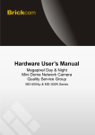
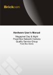
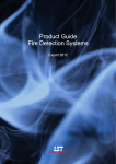
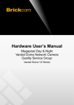
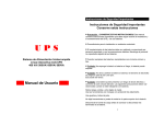
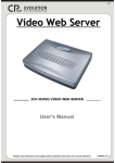
Hardware User’s Manual Megapixel Day & Night Fixed Box Network Camera Quality Service Group FB-500A&FB-300N Series Review History: 1. Separate User Manual into HW and SW. 2. Merge FB-130Ap/FB-200Ap/FB-300Ap v3/FB-400Ap/FB-500Ap Series into this User Manual. 3. Merge FB-300Np into this User Manual. Product name: Network Camera (FB-500A&FB-300N Series) Release Date: 2012/5 Manual Revision: V1.2 Web site: www.brickcom.com Email: [email protected] [email protected] © 2011 Brickcom Corporation. All Rights Reserved Table of Contents Before You Use This Product ...................................................................... 0 Regulatory Information ............................................................................. 1 Package Contents ..................................................................................... 0 Fixed Box Network Camera Overview ........................................................... 1 LED Behavior .......................................................................................... 4 Installation ............................................................................................... 6 Hardware Installation ................................................................................................... 6 System Requirements .................................................................................................. 9 Camera Connection .................................................................................................... 10 Before You Use This Product In many countries, there are laws prohibiting or restricting the use of surveillance devices. This Network Camera is a high-performance, web-ready camera which can be part of a flexible surveillance system. It is the user’s responsibility to ensure that the operation of this camera is legal before installing this unit for its intended use. Upon opening the product’s package, verify that all the accessories listed on the “Package Contents” are included. Before installing the Network Camera, read the warnings in the “Quick Installation Guide” to avoid misuse. When installing the Network Camera, carefully read and follow the instructions in the “Installation” chapters to avoid damages due to faulty assembly or installation. Regulatory Information Federal Communication Commission Interference Statement This equipment has been tested and found to comply with the limits for a Class B digital device, pursuant to Part 15 of the FCC Rules. These limits are designed to provide reasonable protection against harmful interference in a residential installation. This equipment generates uses and can radiate radio frequency energy and, if not installed and used in accordance with the instructions, may cause harmful interference to radio communications. However, there is no guarantee that interference will not occur in a particular installation. If this equipment does cause harmful interference to radio or television reception, which can be determined by turning the equipment off and on, the user is encouraged to try to correct the interference by one of the following measures: - Reorient or relocate the receiving antenna. - Increase the separation between the equipment and receiver. - Connect the equipment into an outlet on a circuit different from that to which the receiver is connected. - Consult the dealer or an experienced radio/TV technician for help. FCC Caution: Any changes or modifications not expressly approved by the party responsible for compliance could void the user’s authority to operate this equipment. This device complies with Part 15 of the FCC Rules. Operation is subject to the following two conditions: (1) This device may not cause harmful interference, and (2) this device must accept any interference received, including interference that may cause undesired operation. IMPORTANT NOTE : FCC Radiation Exposure Statement : This equipment complies with FCC radiation exposure limits set forth for an uncontrolled environment. This equipment should be installed and operated with minimum distance 20cm between the radiator & your body. This transmitter must not be co-located or operating in conjunction with any other antenna or transmitter. The availability of some specific channels and/or operational frequency bands are country dependent and are firmware programmed at the factory to match the intended destination. The firmware setting is not accessible by the end user. Package Contents Please check to make sure that the product package contains all the accessories listed below. a. Network Camera b. CS mount Lens (Optional) c. Product CD d. Camera Stand e. Warranty Card f. A/V Cable g. Power Adapter (Optional) h. Easy Installation Guide i. Allen Key j. C Mount Ring 0 Fixed Box Network Camera Overview The Brickcom Fixed Box series offers a reliable and efficient solution for 24-hour video surveillance. The Fixed Box series offers highly efficient H.264 video compression, which reduces bandwidth and storage requirements without compromising image quality. M-JPEG and MPEG-4 are also supported for flexibility. With the megapixel progressive sensor and removable IR-cut Filter, this series delivers extremely clear and detailed images that CCTV cameras cannot offer. The internal SD/SDHC memory card slot allows for local storage, which prevents data loss if the data connection is lost. Users can view live feed anywhere by internet browser or 3G mobile phone. Also, the Fixed Box series can transmit the video to portable devices through other technology, such as WiMax, NAS, Digital Frame and power line. The Fixed Box series receives power through the same cable as for data transmission. This makes installation easy because there is no external power supply needed. For easy setup, the Fixed Box series offers a step-by-step installation package. “Easy Config” makes the configuration simple even for users without an IT background. With IEEE 802.11 a/b/g/n wireless compliance, network installation is not restricted by location or landforms. The Wireless Fixed Box series can be installed in any location with wireless coverage. It can easily be used to cover remote districts and historic spots. In addition to the motion detection function, the Fixed Box advanced Series can also support Intelligent Video Analysis which can be used for applications such as object tracking, people counting, and forbidden region alarm. 1 Device Appearance Description <Front Panel> Light Sensor <Rear Panel> Reset Button Monitor PAL/NTSC USB Port for 3G/4G Power Connector (DC12V in) Ethernet RJ45 Socket Micro Slot SD/SDHC Extension I/O Terminal Block Microphone/Line In Audio Out NOTE 1. (*) These are optional features. Please refer to the Product List for the full list of optional features available for the product. 2 <CS Mount Lens> <Optional Lens> <Vari-focal Lens with Manual Iris> --- CS Mount Iris Controller (*) Focus Controller Zoom Controller (*) <Optional Lens> <Vari-focal Lens with Auto Iris (DC Drive)> --- CS Mount Zoom Controller Focus Controller 3 LED Behavior Function LED Behavior Blinking Link Link Unlit Power Continuous Illumination Power Unlit Description Remark Blinking while connecting to the network No connection Rear Left (Orange) Normal Operation Power off Rear Left (Orange) Rear Right (Green) Rear Right (Green) Extension I/O Terminal Block The Network Camera provides an extension I/O terminal block which is used to connect the camera with external input/output devices. The pin definitions are listed as below. Pin 1 2 3 4 5 6 Function RS485RS485+ Ground Digital Input Digital Output Power+5V DI/DO Diagram 4 Reset Button Hardware Reset The Reset Button can be used to reboot the camera or restore it to factory default settings. If the camera experiences a problem, rebooting the camera may correct the problem. If the problem remains, please restore the camera to factory default settings and reinstall the software. To Reboot - Press and hold the Reset Button for one second using a paper clip or thin object. Wait for the camera to reboot. To Restore – Press and hold the Reset Button for ten seconds until the LED light turns off. When successful restored, the LED will be blue during normal operation. Note - By restoring the camera, all settings will be restored to the factory default settings. SD Card Capacity (*) The network camera is compatible with SD/SDHC (Maximum 32GB) cards. (*) These are optional features. Please refer to the Product List for the full list of optional features that are available for this product 5 Installation Hardware Installation Mounting the CS-Mount Lens to the Camera <Vari-focal Lens with Manual Iris> --- Optional Lens 1. Connect the CS-mount lens to the camera by turning it clockwise onto the camera mount until it stops. 2. If necessary, adjust the iris controller, focus controller, and zoom controller to get the best resolution. To adjust the lens: 1. Adjust the iris ring controller to control the amount of light coming through the lens. The more the iris is opened, the brighter the scene will be. 2. The zoom controller can be manually adjusted to control the zoom factor on the camera. 3. Users can create a tighter or wider view of the site being recorded. Adjust the focus controller to control the focus range of the lens. 6 <Vari-focal Lens with Auto Iris> --- Optional Lens 1. Connect the CS-mount lens to the camera by turning it clockwise onto the camera mount until it stops. 2. If necessary, adjust focus controller, and zoom controller to get the best resolution. 3. Connect the lens cable plug (DC Iris control cable) to the camera side connector. To adjust the lens: 1. The zoom controller can be manually adjusted to control the zoom factor on the camera. 2. Users can create a tighter or wider view of the site being recorded. Adjust the focus controller to control the focus range of the lens. *For further information of vari-focal lens with auto iris, please refer to the supplied lens’ instruction manual. 7 Connect a Monitor to the Camera: Use an A/V Cable to view the camera’s video feed and manually adjust the lens iris, focus, and zoom to get the desired image quality. 1. Connect the A/V Cable to the monitor. 8 System Requirements Operating System: Microsoft Windows XP Home Edition SP2 Microsoft Windows XP Professional SP2 Computer: IBM PC/AT Compatible CPU: Pentium 3GHz or faster Memory: 1024 MB or more Monitor: 1024 x 768 pixels or more, 24-bit True color or better Network Interface: 10/100Mbps Network interface card must be installed Web Browser: Microsoft Internet Explorer 6.0 SP2 or higher Adobe Reader: Adobe Reader 8.0 or higher Audio: The audio function will not work if a sound card is not installed in the PC. Audio may be interrupted depending on network traffic. 9 Camera Connection Basic Connection (Without PoE) 1. To attach external devices, such as sensors and alarms, connect them to the extension I/O terminal block. 2. Connect the camera to a switch using an Ethernet cable. 3. Connect the supplied power cable to the camera and plug it into a power outlet. Depending on the user’s application, an Ethernet cable may be needed. The Ethernet cable should meet the specs of UTP Category 5 and not exceed 100 meters in length. When powering up, the power LED will light up and the camera will boot up. The link LED will be an illuminate as amber when obtaining the IP address. After obtaining the IP address, the link LED will flash orange while the network connection is processing. 10 Power over Ethernet (PoE) Connection The Fixed Box is PoE compliant, so there are two options for connecting the camera to a power and Ethernet source. The camera can either be connected to a PoE-enabled switch or a non-PoE switch. A. If using a PoE-enabled switch: 1. Use a single Ethernet cable to connect the camera to the PoE-enabled switch. B. If using a non-PoE switch: 1. Use a standard RJ-45 cable to connect the camera to a PoE Injector. 2. Use a standard RJ-45 cable to connect the PoE Injector to the non-PoE switch. 3. Use a standard power cable to connect the PoE Injector to a power outlet. 11