1
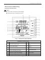
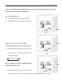
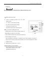
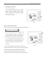
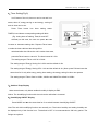
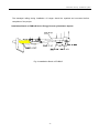
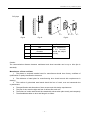
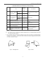
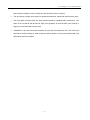
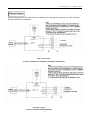
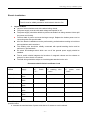
Energy Recovery Ventilation System Installation and Usage Instruction This Instruction is suitable for the following models: D Series: FHBQ-D3.5-K,FHBQ-D5-K FHBQ-D8-K, FHBQ-D10-K FHBQ-D15-M, FHBQ-D20-M Gree Electric Appliances,Inc. of Zhuhai Preface Contents --------------------------------------------------------------------------1 Introduction to Products ---------------------------------------------------------1 Main Features ------------------------------------------------------------------------1 Feature of Structure -----------------------------------------------------------------2 Main Unit -------------------------------------------------------------------------2 Wired Controller (Standard Fitting) --------------------------------------------------3 Outline and Dimension ---------------------------------------------------------9 Equipment Installation -----------------------------------------------------------9 General Description -----------------------------------------------------------------9 Project Design -----------------------------------------------------------------------10 Project Construction ---------------------------------------------------------------13 Installation of Wired Controller ------------------------------------------------------13 Manufacture of Duct and Parts ---------------------------------------------------14 Field Construction ------------------------------------------------------------------16 Electric Project --------------------------------------------------------------------18 Electric Installation ------------------------------------------------------------------19 Operation and Maintenance----------------------------------------------------------20 Check befor Trial Run------------------------------------------------------------------20 Trial Run ----------------------------------------------------------------------------20 Daily Maintenance ------------------------------------------------------------------20 Fault Diagnose -----------------------------------------------------------------------21 Notice for Safety ------------------------------------------------------------------------22 Gree energy recovery ventilation system Preface Our living environments are more and more affected by modern civilization. As the application of air-conditioning system and various composite materials, popularization of office equipments and development of closeness of constructions and for the purpose of energy saving and reduction of cost which cause decrease of fresh air volume, harmful gas and pollution of creature won’t be diluted properly and replaced. Healthy, energy-saving, simple and reliable fresh-air system and equipment has been the focus for engineers and users. Gree energy recovery ventilation system has solved this problem. This kind of system has two-way air exchange function so that the change of indoor temp is little during air exchange. The indoor air can be efficiently filtered by the air filter. New technology and new materials and special technique applied in the unit can ensure low energy consumption, great performance ,low noise and easy installation. Introduction to Products Main Features 1. Replacement and Ventilation Function It introduces fresh air into room and discharges indoor airout of room to make you feel comfortable as in the nature. 2. Energy-recovery Function Internal heat exchanger makes the discharged air and introduced air for cooling and heating exchange. Energy-recovery rate above 70% keeps heat preservation and ventilation realized. 3. Low-noise Design Special low-noise ventilation fan is set. 4. Air Filtration and Purge Function Internal air filter keeps the fresh air introduced into room pure and dustless. 5. Various Series and Multiple Specifications There are various series to match with the buildings of various structures. -1- Gree energy recovery ventilation system Features of Structure Gree heat-recovery ventilation system consists of main unit, wired controller (standard fitting), etc. Main Unit Some parts like low-noise centrifugal fan, heat exchanger and so on are set in the main unit. The air can be filtered effectively against dust particles, fibre etc. before entering into heat exchanger. The filter in the unit can be taken out after opening the service door. The bonded place between case and service door is sealed with long-acting sealing materials to prevent leakage of case. The case is made of hot-galvanized steel plate and the surface of it is bound with insulating sponge to resist noise resulted from operation of ventilation fan and prevent condensate in summer or winter. Fig.1 is the sketch of main structure (service door has been taken out) 1 . R o o m a ir o u tle t 2 .C a s e 3 . F re s h a ir in le t 4 .L iftin g lu g 5 . A ir filte r 6 .H e a t e x c h a n g e r 7 .E le c tric b o x 8 . F re s h a ir o u tle t 9 .R o o m a ir in le t Fig 1 FHBQ-D series heat-recovery ventilation system (standard) -2- Gree energy recovery ventilation system Wired Controller (Standard fitting) Instruction to Wired Controller Notice! ● Never install it in the place with water leakage. ● Never knock, drop or frequently turn on/off it. Fig. 2 Front panel of wired controller Constitution of wired controller 1 Timer display 10 Mode button 2 Energy-saving status display 11 Setting button 3 Setting humidity display 12 Setting humidity decrease button 4 Ambient humidity display 13 Fan speed button 5 Air exchange mode (half-half exchange ,discharge and supply) * 14 Reset/Switch button 6 Fan speed display (high, mid, low) * 15 Timer button 7 Mode(auto, by-pass, heat exchange) 16 On/Off button 8 Error status display 9 Cleaning status of filter display -3- air humidity increase Gree heat recovery ventilation system Notice: For FHBQ-D15-M and FHBQ-D20-M, there is no air discharge and supply function in Item 5 and the fan speed in Item 6 is unadjustable. 1) Turn On / Off the Unit Press ON/OFF button to start the unit. (Fig.3) Press ON/OFF button once again to stop the unit. Fig.3 2)Fan Speed Control (Fig.4,5)(The figure is about relative display area , the same as below) During half-half air exchange, With each press of FAN button, the fan speed will change in the Fig.4 following order(Fig.4): →Low→Med.→High→ Note: No change to fan speed of FHBQ-D15-M and FHBQ-D20-M during control During air discharge and air supply, with each press of FAN button, the fan speed with switch between high speed and low -4- Fig.5 Gree heat recovery ventilation system speed(Fig.5). →Low→High→ Note:No this function for FHBQ-D15-M and FHBQ-D20-M during control 3)Humidity Adjustment (Fig.6) If there is humidifying function in the unit, press humidify button: ▲:Used to increase setting humidity. ▼:Used to decrease setting humidity. Once press of this button, the temperature will increase or decrease by 5%. Note:Lock function: Pressing ▲ and ▼ simultaneously for 5s, the place of setting humidity will display EE and all response to the buttons Fig.6 will be shielded. And then press ▲ and ▼ simultaneously for 5s to release Lock Function. When long-distance monitoring or centralized control shield displayer, the signals of buttons and from remote controller will be shielded, and CC will be displayed in the place of setting humidity. Setting range of humidity: 30%~70% 40%~60%RH 4)Reset/ Switch Function Setting Not having pressed Timer button, long press Reset/ Switch button for 5s to clear operation time and icon. -5- Gree heat recovery ventilation system After pressing of Timer button: Under On status of the unit: short press Reset/ Switch button to switch among Timer off setting, Energy saving startup setting,Energy saving stop setting and Clear time setting. Fig.7 5)Running Mode Setting (Fig.8) Each press of this button, the operation mode will change as follow, →Auto→By pass →Heat exchange Bypass Under Auto mode, the letter of Auto will light, so the system will operate according to temperature and temperature difference between room and outdoors. Under By pass mode, the letter of By Pass will light, so the fan will operate according to setting Fan mode and fan speed. Make this mode operate in transient season to prolong service life of the core of heat exchanger. Fig.8 Under Heat Exchange mode, the letter of Heat Exchange will light. After shutdown of air valve, the fan will operate according to setting fan mode and fan speed. Under this mode, the total heat exchange of temperature and humidity can be realized along with exchange of fresh air, which is energy saving and healthy. -6- Gree heat recovery ventilation system 6)Timer Setting(Fig.9) In off status of the unit, timer on can be set and in on status, timer off, energy-saving on and energy –saving off and air clear can be set. Press Timer button into timer setting status. TIMER,Hr and letters corresponding setting will blink. (E.g. during timer off setting, Timer,Hr and OFF will flash).In this case, the user can press ▲or ▼to increase or decrease setting time. Repress Timer button to make the timer valid and the timing will be Fig.9 calculated after that. When the unit is under timer state, press theTimer button to cancel it. The time interval is 0.5 hr. The setting range of Timer on/off is 0.5-24hr. The setting range of Energy Saving On is 2-5hr and the default is 2hr. The setting range of Energy Saving Off is 1-4hr and the default is 1hr. (Note: press FAN and ▼ at the same time for 5s only after energy saving timer setting, the energy saving function can operate. The setting range of Timer Clear is 1250hr, 2500hr and 00000.The default is 1250hr. 7)Ambient Temp Display Under normal state, only indoor ambient humidity is display at ENV. Notice: The humidifying function with the unit can be valid after it is started. 8)Humidifying ON/OFF Display Press MODE and ▼at the same time for 5s to switch between humidifying ON/OFF. Note:The unit with humidifying function can normally run. The indoor humidity and setting humidity can be displayed only If this function is on. The default is OFF. It is recommended to ON in dry period. The fittings are optional. -7- Gree heat recovery ventilation system 9)Fan Mode Display Press FAN and ▲ at the same time for 5s to switch among half-half air exchange, discharge and supply. Refer to Fig.2 for details. The fan mode is selected by the users. E.g. plus pressure is needed in the room, fan mode can be adopted and if negative pressure is needed, air discharge mode can be adopted. Half-half air exchange is for normal station. 10)Energy Saving Mode Display Press FAN and ▼ at the same time for 5s to switch between energy saving on/off. If under energy saving on state, Energy Saving will be displayed. Refer to Fig.2 for details. If the unit needn’t operate for a long time, energy saving mode can be adopted to meet the demands of both function of fresh air exchange and quality of indoor air by users. 11)Fault Display If fault happens during operation of the system, “ERROR” and error code will be displayed in the displayer.(Timer can not be displayed) Error Code Error E6 Communication error F0 Indoor temp sensor error L1 Humidity sensor error F3 Outdoor temp sensor error L0 Air valve and relevant fitting error or wrong connection of centralized control wiring of air valve 12)Intelligent 0n-off Intelligent on-off which is applied in a unit to connect air valves in many rooms is also centralized control to air valve. A piece of pinboard can be used to connect with up to 18 air valves. Many pieces of -8- Gree heat recovery ventilation system Outline and Dimension pinborad can also be used to connect with more air valves. The pinboard is special fitting. Fig. 10 Outline and Dimension Model A A1 B B1 C C1 D E F G H N FHBQ-D3.5-K 879 823 800 852 306 125 90 125 175 136 416 197 FHBQ-D5-K 879 823 800 852 306 125 90 125 175 136 416 197 FHBQ-D8-K 1016 960 832 884 380 165 90 150 230 155 372 246 FHBQ-D10-K 1016 960 832 884 380 165 90 150 230 155 372 246 FHBQ-D15-M 1215 1159 1210 1262 452 200 100 190 277 178 737 297 FHBQ-D20-M 1215 1159 1210 1262 452 200 100 190 277 178 737 297 Equipment Installation General Description Models selection and project design should be performed by professional engineer in terms of heating and ventilation and the project should be constructed by experienced construction organizations according to national criteria and rules. Once the unit can not operate normally because the user fails to conform to the requirements for installation, our company will charge the user for after-sales service. -9- Gree heat recovery ventilation system Project Design This unit should be equipped with two ventilating ducts for two-way ventilation between room and outdoors. One duct is used to introduce fresh air into room and the other one is used to discharge indoor airout of room. Some resistance will result to the air through the duct. The greater the resistance is, the lower the ventilation quantity is, so long duct, small caliber, or big quantities of elbows will result in great resistance to the air in the duct and low ventilation quantity. Please perform design and installation according to the following principles: 1. Either of the ducts can not exceed 15─30m long(according to models).Internal cross-sectional area of the duct is decided by internal fan speed, about 8m/s in main pipe and about 5m/s in branch pipe. If rectangular duct is used, the scale of length between two sides can not exceed 4.The duct should be made of noncombustible materials. 2. Use elbows as few as possible, which should be within 3 for either duct. The bending part can never be 90º but arc, as shown in fig.12,13. Fig.11 Elbow type Fig.12 Arrangement of duct 3. The inwall of the duct should be slick, dustless and unfolding. 4. Keep air resistance of decorative vent on outdoor wall and indoor ceiling low. It is better to install rectangular aluminum alloy diffuser or two-layer louver with caliber of above 200×200mm.If the outdoor vent is waterproof louver, its caliber area should be 3-4 times bigger than cross-sectional area of duct connecting with it. The air flow can pass through the louver smoothly. The selection of outdoor vent is shown as fig.13. 5. The distance between the two vents should be above 1000 ㎜ to prevent exhausted air from returning into room from fresh air inlet. - 10 - Fig.13 Outdoor vent Fig.14 >1000mm <1000mm Gree heat recovery ventilation system Distance between outdoor vents 6. If the user intends to lower the indoor noise as much as possible, muffler can be concatenate with duct and be installed with the guidance of professionals. The noise at vent of unit can usually be decreased by 4—6 dB after setup of suitable muffler. 7. If electric heater is set in the duct, its switch should be interlocked with that of ventilation system, i.e. it only can start after ventilation fan start to run. The duct had better adopt incombustible materials. 8. The air filter core should be replaced periodically, so maintenance space should be reserved at one side of fresh air ventilation system during installation. 9. The steel hanger should be pre-built in the ceiling for cassette energy recovery ventilation system according to its specification and weight to ensure firmness and reliability of installation. If the project is reconstructed, the hanger should be put after drilling holes in the ceiling, as shown in Fig.15 (a).If it is not convenient to drill holes, through chiseling the concrete, find out the inner steel bars which can hang the hanger as shown in fig.15 (b). Hanger Ceiling Fig.15(a) Inner steel bar Hanger Ceiling Fig.15(b) - 11 - Gree heat recovery ventilation system The damaged ceiling during installation of hanger should be repaired and recovered before completion of the project. Installation Sketch of FHBQ-D Series Energy Recovery Ventilation System Fig.16 Installation Sketch of FHBQ-D - 12 - Gree heat recovery ventilation system During installation, the two ducts (fresh air inlet and indoor airoutlet) outside the room must be installed with anti-condensate and heat insulating materials, and the ones inside the room should also be installed with them if temperature and humidity in the ceiling is high. The ducts outside the room should be kept inclined 1/50~1/30 to avoid water into room. In order to clean and maintain the filter and heat exchanger core in the system, do keep service space, as shown in fig.17. 新风进口 污风出口 ! W a r n in g 检修口space Service 新风出口 Fresh air outlet 污风进口 Dirty air inlet Fig.17 Maintenance space figure Project Construction Installation of Wired Controller 1. Locate the installation position firstly, and then reserve a groove or hole for embedding of communication wire according to its dimension. 2. If wired controller and indoor communication wire are mounted visibly, 1#PVC pipe can be used and corresponding grooves should be set in the wall (fig.18).If in hidden, 1#PVC pipe can be used (as shown in fig.19). 3.Whether mounted visibly or in hidden, drill two holes (keep level) in the wall as the distance (60mm) between the two holes in underplate of wired controller, and then inset stopper into the holes through which the wired controller can be fixed. Insert communication wire in the control board. At last, clasp the controller panel. Note: During installation of underplate of wired controller, pay attention to its direction. The side with 2 breaches must be kept downwards. - 13 - Gree heat recovery ventilation system PVC管 PVC pipe 1 Fig.18 Fig.19 2 3 4 Fig.20 No. Name Remarks 1 Wall 2 Underplate of wire controller 3 Screw M4X10 The appearance of the controller should be subject to entity. 4 Controller panel Caution: The communication distance between mainboard and wired controller can be up to 20m (8m is standard). Manufacture of Duct and Parts 1. The plates or sectional material used for manufacture should have factory certificate of qualification or quality identification document. 2. The thickness of steel plate for manufacturing duct should accord with requirements in drawing. 3. The surface of galvanized steel metal should be free of crack, scar and watermark but crystal texture. 4. The specification and dimension of duct must accord with design requirements. 5. The joint of duct must be tight and free of defects like crack etc. 6. The surface of carbon steel should be coated with anticorrosion paint evenly and compactly. 7. The allowable deviation to duct and flange is as follow: - 14 - Gree heat recovery ventilation system Allowable deviation to manufacture of duct and flange Allowable No. Item deviation Check Method mm 1 2 External diameter of round duct The longer edge of rectangle duct φ>300mm 4 Diameter of rectangle flange 5 Difference Diameters form 90° measured 0 by ruler 0 -1 0 >300mm Diameter of round flange -1 -2 <=300mm 3 between 0 φ<=30mm Check by ruler -2 +2 Diameters form 90° measured 0 by ruler +2 0 diagonal 3 Check by ruler Check by ruler lines of rectangle flange 6 Planeness of flange 2 7 Planeness of weld joints of 1 flange Put them on the platform to check with feeler 10. The absolute value of difference between diagonal lines of rectangle flange should be |L1-L2|≤3, as shown in fig.21. 11. The verticality tolerance between the flanges at two ends of the elbow of rectangle flange should be 3.0(90°elbow), the absolute value of difference between diagonal lines should be |L1-L2|≤3, as shown in fig.22. Fig.21 Fig.22 Elbow Rectangle duct - 15 - Gree energy recovery ventilation system Field Construction 1. Never lay wires, cables and pipes with toxic, inflammable or explosive gas or liquid in the duct. 2. The dismountable ports and adjustable parts of duct and fittings can not be installed in the wall or floorslab. 3. The sundries and filth in or on the duct and fittings should be cleaned before installation. 4. The construction of bracket or hanger of the duct should accord with the following specifications: 1) The build-in fitting, setting nail or expansion bolt for bracket or hanger should be placed correctly and firmly .The inlet part should be free of oil soil and painting. 2) The layout of the bracket or hanger should accord with design specifications. If there is no design specification, following specifications will apply. a. Pole bracket or inclined bracket is applicable for horizontal duct against wall or pole and support bracket for that far from wall or pole. Strip hanger is applicable for the duct with diameter or length of side below 400mm. b. Arm bracket or inclined bracket is applicable for vetical duct against wall or pole and anchor ear bracket for that far from wall or pole .The vertical pipe outside the room or on the roof should be fixed with derrick or dragline. 3) The hanger’s rod should be flat and its screw thread should be full and smooth. Either threaded connection or welding is suitable for joint of hangers. If the former one is adopted, connecting thread of either end should be longer than diameter of hanger; moreover, anti-loosing measure should be made. If the later one is adopted, lapping joint is applicable and its length should be 6 times longer than diameter of hanger at least at two sides. 4) The holes on the bracket and hanger should be drilled mechanically and not with gas cutting. 5. The bracket and hanger can not set at air vent, valve or service door. The hanger can not be directly fixed at flange. The distance between horizontal duct bracket and hanger can not exceed 4m.If the duct is installed vertically, the distance between them should not exceed 4m - 16 - Gree energy recovery ventilation system and the built-in fittings of each vertical duct should be more than 2 pieces. 6. The duct flange, hanger and hanger for equipment should be coated with anticorrosion paint. 7. The floor plate and wall which the duct passes should be repaired after construction. The holes on the external wall should be kept 2/100 gradient at level direction (the internal is higher) to avoid rainwater into the room. 8. Installation of duct and connection between air vent and duct should be firm. The frame and decorative surface should be solid, external surface should be level and indeformable and adjustment should be flexible. - 17 - Gree energy recovery ventilation system Electric Project External wiring figure of the unit(If this one is different from wiring figure of junction box, take the wiring box of junction box as standard) Fig23 Wiring figure (suitable for FHBQ-D3.5-K;FHBQ-D5-K;FHBQ-D8-K;FHBQ-D10-K) Fig24 Wiring figure (suitable for FHBQ-D15-M;FHBQ-D20-M) - 18 - Gree energy recovery ventilation system Electric Installatrion ! Notice The AC must be reliably earthed to avoid electric shock or fire. 1. Layout of Wires z Layout of wires should accord with national wiring criteria. z The power supply must be with rated voltage and special for AC. z The power supply should be reliable to prevent terminals from being stressed. Never pull the power cord forcibly. z The line width of power cord must be large enough. Replace the broken power cord or connecting wire with special cable. z All of the electric installation must be performed by professionals according to local laws and regulations and instructions. z The earthing wire should be reliably connected with special earthing device and be performs by professionals. z Air switch and leakage switch which can cut off the general power supply should be installed. z The air switch should integrate the functions of magnetic release and hot release to protect it for short circuit or overload. z The field wiring should be subject to circuit diagram attached on the unit. Recommended Air Switch and Power Cord Applied models Power supply Capacity of air switch (A) Min. sectional area of earthing wire (mm2) Min. sectional area of power cord (mm2) FHBQ-D3.5-K 220V~ 50Hz 6 1.0 1.0 FHBQ-D5-K 220V~ 50Hz 6 1.0 1.0 FHBQ-D8-K 220V~ 50Hz 6 1.0 1.0 FHBQ-D10-K 220V~ 50Hz 6 1.0 1.0 FHBQ-D15-M 380V 3N~ 50Hz 6 1.0 1.0 FHBQ-D20-M 6 1.0 1.0 380V 3N~ 50Hz Note: The power cord of the unit must be copper cored cable, and working temp can not exceed specified value. b. Increase the sectional area of power cord above 15 meters to avoid overload. - 19 - Gree energy recovery ventilation system 2. Earthing Requirements z Reliable earthing measure must be adopted. The yellow green earthing wire with the only use never can be cut off and fixed with tapping screws to avoid electric shock. z Earthing resistance should be accord with national criteria GB17790. z Power supply must be reliably earthed. The earthing wire can not connect with: 1. Tap water pipe; 2. Gas pipe; 3. Blowing tube; 4. Place which specialist considers unreliable. Warning: Cut off the power supply before installation and maintenance to avoid electric shock. Arrange wirings according to requirements strictly to avoid malfunction, electric shock or fire. Special Notice: The company won’t be responsible for bad results because users self-modify the electric control system without consent of the company. Operation and Maintenance Check the connecting wires and perform trial run after installation work. Check before trial run 1. Check of pipeline system According to design drawing and instruction check bearings of duct, firmness of hanging of the equipment, anticorrosion paint of hanger and the said items which should be paid attention to as well as operation space for replacement of air filter, installation location of duct muffler, the inside or top of the duct or equipment for sundries or mounting tool and firmness of installation of duct vent. 2. Check of circuit system According to circuit diagram, check the connection and voltage of power cords. Trial Run (1) Power the unit on to start the unit. Refer to the section of instruction to operation of wired controller. (2)If there is any malfunction, cut off the power supply and refer to fault diagnosis and check. Daily Maintenance Air filter must be installed, if not, heat exchange core will be covered with feculence and dust so that its performance will be reduced. If airflow volume or discharge air volume is obviously decreased, filter should be replaced for overmany dust. Setting of replacement period may be displayed in the displayer or according to actual condition in each area. - 20 - Gree energy recovery ventilation system Fault Diagnose After debugging and trial run, the unit can be normally used by the user. If any fault occurs, remove it firstly by yourself according to the following table before you contact us. Phenomenon Airflow volume at air outlet/inlet is obviously decreased after a period of time. Noise occurs at air vent The system can not be started Possible causes Too much dust gathers on the air filter Installation of air vent is loose No power supply or power cord is incorrectly connected Terminals of mainboard transformer are loose Communication fault (E6) Air valve and relative fittings are faulted(L0) The centralized controller of air valve of mainboard is not connected (L0) - 21 - Solutions Replace or clean air filter Re-fix the collecting place of air vent Repair the power supply and check power cord according to circuit diagram on the unit Re-insert and connect transformer terminals Check the connecting wire between displayer and mainboard Check by-pass door and drive structure of the unit and fix it Connect CONTROPL port of mainboard with live line or pinboard of air valve Gree energy recovery ventilation system Before installation, please carefully read Notice for Safety. Be sure to conform to the following items to prevent damage to users or others. Notice for Safety The damage and degrees resulted from incorrect operation are as follow: ! Danger This mark means that dangerous cases like death or grievous harm will happen. This mark means that dangerous cases like death or grievous harm may happen. ! Warning This mark means that injury or damage to property may happen. ! Notice The contents needed to be conformed are defined as follows. This mark means that something can not be performed. ! These marks mean that something must be performed. ! Warnig lease ask professionals for installation.Never install, move or refit the unit by yourself. Improper operation will cause falling, electric shock ,fire and so on. Forbid Install the unit strictly according to the instruction. Improper operation will cause electric shock ,fire and so on. ! ! Dangerous Dangerous Install bird net and suchlike things at air exchange vent. The air inlet should be installed at the place far from exhaust vent for fuel gas. ! ! Clean up sundries like nest to avoid deficiency of oxygen in the roon. Notice ! Notice It's easy to cause deficiency of oxygen in the roon. Dangerous The unit should be installed at the place with enough strength and reliability. The electric project should be constructed according to national rules and constructio instruction. Install the air inlet at the place where exhausted air can not flow backwards. ! It's easy to cause pollution of the room and damage the health. Force The earthing wire can not connect with gas pipe,water pipe, lightning rod, phone line and so on. Some places are not strong enough for structure of the buildings. Poor capacity of power cord or improper construction will cause electric shock ,fire and so on. Improper earthing will cause electric shock. Dangerous Turn off the switch and special circuit breaker during maintenance of the unit. ! Dangerous - 22 - It's easy to cause electric shock. Gree energy recovery ventilation system !Warning Never insert finger or stick into suction or discharge vent. It is easy to cause injury that the fan runs at high speed. Forbid Use the unit according to rated voltage. It is easy to cause electric shock or fire. Forbid Ventilate the room by opening the window if flammable gas leaks. Never refit ,disassemble or repair the unit by yourself. ! Danger Improper repair may cause electric shock or fire. The spark electric contact may cause explosion or fire after the unit starts. Forbid Stop the unit and turn off special breaker once paticular smell occurs. Never put animals or plants against air vent. ! ! Continuous operation in abnormal state may cause malfunction Danger ,electric shock or fire. It may cause bad effect to animals and plants. Notice Make insulated layer between pipe and wall if metal pipe goes through metal sheet or mesh of wooden building ! It is easy to cause electric shock or leakage. Must For easy repair and cleaning of filter and heat exchanger core in the unit, make sure to reserve proper maintenance space. - 23 - Gree energy recovery ventilation system ! Notice Take waterproof m esures for the unit. Do not put the buruning appliances at the place against the air vent. ! It is easy to cause insufficient burning of the burning appliances. If water leaks, it will enter into the unit and dam age electrical insulator . Forbid ! It is easy to cause incorrect operation and result in bad effect to switch and internal relay. Notice Periodically clean the filter. ! If water leaks, it will enter into the unit and dam age electrical insulator and cause electric shock. Danger O perate the switch correctly. Never quickly repeat. Too m uch dust attached on the filter will cause hypoxia in the room . Notice Do wear gloves to clean filter and heat exchanger. It is easy to cause injury. Forbid Turn off the breaker if the unit will not be in use for a long tim e to ensure safety. ! Too m uch dust will heat and cause fire. Notice Do not install the unit against fire soure or at the place where there is naked flam e. It is easy to cause electric shock or leakage. It is easy to cause electric shock. Forbid Notice Do not install the unit at the wet place like bathroom ,etc. Never operate the switch with wet hand. It is easy to cause electric shock. Danger ! It is easy to cause fire. Forbid Never wash the m ain unit with water. ! Do not use flam m able spayer near the m ain unit. Do not install the unit at the place where there is leakage of flam m able gas. It is easy to cause heat or fire. Forbid If there is leaked gas around the unit, fire is easy to result. Forbid Do not install the unit at the place where there is acid,alkaline , organic resolvent,paint and other harm ful or corrosive gas, like chem ical plant,etc. M aintenance space m ust be reserved.(m aintenace place) It is easy to cause poisoning and fire. ! Forbid Notice !Danger Open system burning equipmets (warm air) for air exchange can not be used. If gas or oil heater is used in the room,special ventilation equipment must be used. Forbid - 24 - It is convenient to clean heat exchanger core and filter and m aintain the equipment. Gree energy recovery ventilation system In order to install and use this unit correctly, please read this installation and usage instruction carefully. Gree Electric Appliances , Inc. of Zhuhai 66176036 66129902253