1
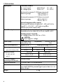
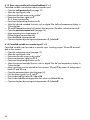
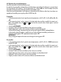
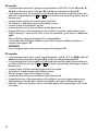
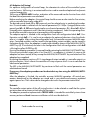
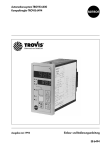
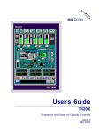
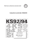
Automation System TROVIS 6400
Compact Controller TROVIS 6494
Edition June 1994
Mounting and operating instructions
EB 6494 E
Contents
Page
1.
Description
4
1.1
1.2
Version
Technical data
4
6
2.
Installation
7
3.
Electrical connections
8
4.
Operation
10
4.1
4.2
Control panel, displays and operating elements
Operation of the three levels
10
12
4.2.1
Operating level
Modify setpoint W1
Display sensor line breakage
12
12
13
4.2.2
Parameterization level
Determine and modify the control parameters
Open the parameterization level
Proportional-action coefficient P (Kp)
Integral-action (reset) time I (Tn)
Derivative-action (rate) time d (Tv)
Derivative-action (rate) gain dP
Output variable limits Y__and Y—
Working point YP
Limit values 1A and 2A
Differential gap 1H and 2H
Duration of switching period and motor operating time t1
Dead band (neutral zone) td
Hysteresis th
14
14
14
15
15
15
15
15
15
15
15
16
16
16
4.2.3
Configuration level
Determine and modify controller functions
Open the configuration level
Select input signal In
Measuring range limits In__and In—
Decimal point Ind
Select the current or voltage ranges of controlled variable x with In0
Unit of temperature Int
Digital filter InF
Select the input circuitry of the D (derivative)-action component with dI
Select setpoint SP
Setpoint ramp SPr
Inhibit (HOLD) modification of setpoint SPH
Lock (HOLD) the MANUAL/AUTOMATIC key YH
17
17
17
18
18
18
18
19
19
19
19
20
20
20
2
Page
Contents
Select controller output Y
Operating direction Yr
Select the current range of controller output Y with Y0
Safety output (restart) value YSt
Limit alarm condition for switching output Y1
Switching output Y1 as break or make contact Y1C
Limit alarm condition for switching output Y2
Switching output Y2 as break and make contact Y2C
Adaption (self-tuning) AdP
Enter code numbers CPA and CCO
Code number for servicing
Figure, setpoint ramp SPr
20
20
20
21
21
21
21
22
22
22
23
23
5.
Switching outputs Y1 and Y2
24
5.1
5.2
5.2.1
5.2.2
5.2.3
5.2.4
5.2.5
5.2.6
Three-step controller with internal feedback (Y = 1)
Limit contacts
General definition
Assignment of the limit alarm conditions for switching outputs Y1 and Y2
Monitor output signal Y
Pulse-modulated on-off controller output at switching output Y1 and/or Y2
On-off pulse-modulated controller output with limit alarm
Two pulse-modulated on-off switching outputs
25
26
26
27
27
28
28
28
6.
Start-up procedure
29
6.1
6.1.1
6.1.2
6.1.3
6.2
6.3
6.4
EEPROM version
Configure the different controller outputs
Continuous-action controller (Y = 0)
Three-step controller with internal feedback (Y = 1)
Controlled variable x as recorder input (Y = 2)
Optimize the control parameters
Adaption (self-tuning)
Checklist
29
29
29
30
30
31
33
34
Figure depicting front view, see folding page on back cover
36
3
1. Description
TROVIS 6494 is a digital controller integrating many sophisticated functions into a single compact module used to automate plants used in industrial applications and process engineering.
Its well-thought functional design, which takes user needs into mind, allows diverse control circuit arrangements to be configured. TROVIS 6494 can be effectively used in a wide-range of
applications as a either a continuous-action controller, on-off (two-step) controller or three-step
controller with the option of P (proportional), PI (proportional-plus-integral), PD (proportionalplus-derivative) or PID (proportional-plus-integral-plus-derivative) action.
Self-tuning, a standard option, uses the built-in intelligence capabilities to automatically determine and set the appropriate control parameters.
Operation of this advanced controller is designed according to the concept of user friendliness
and uses the following three-level operating structure: 1) operating level (standard operation),
2) parameterization level and 3) configuration level.
The first level, the operating level, contains visual displays for standard control operation and
can be accessed at any time, whereas the parameter and configuration levels are protected by
user-definable code numbers. Functions in the second level, the parameterization level, include
modification of control parameters and optimum adaption to the controlled system. Selection of
controller functions is facilitated in the third level, the configuration level.
Controller input options include the following: Pt 100 resistance thermometers, Ni 100 resistance thermometers and standardized current/voltage signals.
The controller’s command variable, to be called the setpoint (SP) in the remainder of this text for
reasons of conformity, can be selected between setpoint W1 and setpoint W2 via a key, or by
means of a binary signal.
Bumpless transfer in the respective operating mode (MANUAL or AUTOMATIC) is facilitated by
means of the MANUAL/AUTOMATIC key.
1.1 Version
This compact controller is delivered in panel-mount design according to DIN 43 700 (dimensions of front frame: 48 mm x 96 mm) as the following versions:
Universal input options:
Ni 100 or Pt 100 resistance thermometer in three-wire circuit, standardized mA/V signals
Standard controller output:
Continuous/on-off/three-step/limit contact
Power supply:
100 to 253 V AC (TROVIS 6494-0111)
20 to 30 V AC (TROVIS 6494-0121)
Connection:
Crimp contacts or optional screw terminals
This manual applies to controllers implementing firmware version 1.00 or later
WARNING
Assembly, commissioning and operation of this controller may only be performed
by experienced personnel.
4
Fig. 1 ⋅ Functional structure of controller
5
X
In
In0
0
Digital filter
1,2,3
SPh
InF
W1
On
2,3
1,2
SPr
Setpoint ramp
W2
4
_
+
SP
dI
ext. BE
P
dP
d
P
I
P
D
I
P
Setpoint key W1/W2
Inhibition (HOLD) of setpoint modification
Y PID
Yr
Operating
direction
+
MANUAL/
AUTOMATIC
key
YSt
Safety output
(restart) value YH
YHd
Y
1
0,2
0,2
Y0
YY-
0
1,2
Three-step
on-off
-Switching
-Clocked
for Y = 1
————————
Limit contacts
for Y = 0,2
Output analog
0(4) to 20 mA
Y or X
1.2 Technical data
Input options
Controlled variable x
d.c. current signal
d.c. voltage signal
Ri = 50 Ω
Ri > 100 kΩ
4(0) to 20 mA
2(0) to 10 V
Resistance thermometer Pt 100 (three-wire circuit)
Measuring ranges
–100.0 to 400.0 °C
–30.0 to 150.0 °C
Resistance thermometer Ni 100 (three-wire circuit)
Measuring ranges
–60.0 to 180.0 °C
–20.0 to 90.0 °C
External changeover of the setpoint
Binary input for selection of setpoint W1 – W2 with 24 V d.c.
Signal 0 V → W1; 24 V → W2 (select using SP) or
external restart of the setpoint ramp
Controller outputs
Standardized output signals
Standardized current signal 4(0) to 20 mA, load RB < 650 Ω
Switching outputs Y1 and Y2
a.c. voltage contacts 24 to 250 V a.c./0.5 A
CAUTION:
Never apply d.c. voltage
Power supply
Permissible temperature
Measuring accuracy
mA, V, Pt 100, Ni 100
Temperature effect
100 to 253 V a.c.
48 to 62 Hz, 7 VA
Ambient 0 to 50 °C
or optionally
20 to 30 V AC/DC
7 VA
Shipping and storage 0 to 70 °C
Linearity error
Zero error
Span error
0.2 %
0.2 %
0.2 %
Zero error
Span error
Pt 100, Ni 100
0.3 % / 10 °K
0.3 % / 10 °K
mA, V
0.2 % / 10 °K
0.2 % / 10 °K
Utilization category
according to DIN 40 040
Humidity rating F
Degree of protection
IP 54 (front side), IP 20 (encapsulation)
Power failure
All control parameters and configuration blocks are stored in a
non-volatile EEPROM protected against power down (i.e. nobattery design)
Weight
6
0.3 kg
2. Installation
TROVIS 6494 is smartly engineered as a panel-mount unit, the front dimensions of which compactly measure 48 x 96 mm2. A panel cut-out of 45+0.6 x 92+0.8 mm2 is to be fabricated for assembly of the plastic enclosure. After sliding the controller in the panel cut-out, the supplied
clamps depicted in Fig. 3 are to be locked in place at the top and bottom in the accommodating
pins of the enclosure. A screw driver can consequently be used to turn the threaded rods, clamping the controller’s front frame against the panel.
123 (4.84)
48 (1.89)
96 (3.78)
89.5 (3.52)
111 (4.37)
Fig. 2 ⋅ Dimensions in mm (inch)
Front
Pivot
Front
2)
Lock in
place
1)
Inserting on pivot
and turning
Fig. 3 ⋅ Assembly
3)
Screw tight
7
3. Electrical connections
The easy-to-install compact controller is equipped with plug-type connectors (snap-in contacts)
for lead sizes 0.3 to 0.8 mm2 and an insulating diameter of 1.3 to 2.4 mm2 or screw terminals
for lines 0.5 to 1.5 mm2. When connecting the electric leads, note the pertinent VDE 0100 regulations and the currently valid regulations mandated by the country where the controller is intended for use.
Wiring information
The signal and sensor leads are to be isolated from those of the controller and power supply.
To avoid measuring errors when radio interference is present, use shielded lines for signals and
sensors.
The power supply lines of each controller are to be led separately to the corresponding distributing bus bar.
Suppress contactor circuits located in the vicinity against interference using an RC element.
Terminals X1
Snap-in Contacts
Back
X1
X2
A1
B2
C3
A1
B2
C3
D4
E5
E5
F 6
G7
H8
G7
H8
Power supply
100 to 253 V a.c.
or 24 V a.c./d.c.
Three-step switching output
for a current >0.5 A requires
contactors or relays
2 x limit contacts (TRIAC)
1 C
5
F
7 H
5 F
7 H
Y2
+
_
_
+
N
L
Y1
Note:
Y1 or Y2 can only be operated with
a.c. voltage. Note correct phase
connection of power supply.
Code
L
N
Terminals X2
Controller input (controlled variable x)
Pt 100/Ni 100
5
E D
4(0) to 20 mA
2(0) to 10 V
4 C
3 C
+ mA
+ -
Screw terminals
H 7 F 5 C 1
X1
5 E C/D 4 3 2 A/B 1
Back
X2
Binary input BE
0/24 V
2
B
+ -
V
Controller output (output signal y)
(continuous) 4(0) to 20 mA
1
A
+ mA
Note:
When using a three-step switching output or limit contacts,
the continuous controller output is available as analog output
for controlled variable x.
Fig. 4 ⋅ Terminal assignment
8
Pt 100
Ni 100
x-Recorder
4(0) to 20 mA
V
mA
5
E
D
PE
PE
PE
+ -
HE
4
C
+
_ I
3
C
+
_U
+
Y_
1
A
Y1
F
5
Y2
L N
BE
+ _
1 C
2 B
PE
7
H
t
A
+ L
HE
+ _
24 V DC
_
N PE
+
Y1 and Y2 can defined by the user for use
as limit values or motor drive
Fig. 5 ⋅ Diagram of connections
WARNING
Always disconnect the power supply lines prior to plugging/removing the plug
connectors.
If this is ignored, the glass fuse Type T63 mA/250 V (order no. 8834-0298) contained on the power board in the device may be required to be exchanged.
9
4. Operation
4.1 Control panel, displays and operating elements
°C
11
1
XD
10
2
Y
W2
7
3
XD
5
4
Y1
Y2
8
W2
W1
6
9
Fig. 6 ⋅ Front view
1
Controlled variable display (top display)
Controlled variable x, sometimes referred to as the Process Variable PV, is displayed in the
operating level. The value of the selected entry option is can be viewed in the parameterization and configuration level.
2
Setpoint (SP) display
The current setpoint is displayed in the operating level. The display mode can be modified
in the following sequence by actuating the operating key (7): setpoint W1, control deviation
(error) XD, output variable Y, setpoint W2.
Configuration blocks and parameters values are presented in both the configuration and
parameterization levels, resp.
3
Control deviation
Whenever xd is greater than 0.9 % or less than –0.9 %, the red LED (light-emitting diode) illuminates.
4
Display of switching outputs Y1 and Y2
Two red LEDs display indicate the circuit state of the three-step/on-off controller output, or
the limit alarms.
10
5
Cursor keys
Increase displayed value
Decrease displayed value
Function in the operating level (standard operation):
After selecting setpoint W1 or W2 → (modify setpoint directly), acknowledge the value
using ENTER key (8).
In MANUAL operating mode:
Direct adjustment of output signal Y.
Function in the parameterization/configuration level:
Selection of the individual entry options in both directions.
Adjustment of the related numeric value in the top display (1).
6
MANUAL/AUTOMATIC changeover
When selecting manual adjustment to either controller output Y or switching outputs Y1 and
Y2, the yellow LED located in the key illuminates:
Using the MANUAL/AUTOMATIC key, the controller can be bumplessly switched over from
MANUAL to AUTOMATIC operation (or vice versa).
The MANUAL setting allows the user to directly operate the connected control valve. Controller output value Y can be modified using cursor keys (5)
and . In MANUAL operating mode, the controller output value can be viewed in the bottom display panel.
7
Operating key
Function in the operating level (standard operation):
Switch over to select the controller variables in one direction; following sequence: setpoint
W1, XD, output variable Y, setpoint W2 (see section 4.2.1).
Function in the parameterization/configuration level:
Return to the operating level (standard operation) from the current levels.
8
ENTER key
Function in the operating level (standard operation):
Accept and store the numeric value specified for setpoint W1 or W2. Access the code numbers for parameterization level PA and configuration level C0.
To acknowledge the code number entered and simultaneously enter the selected level.
Function in the parameterization/configuration level:
Selection of the entry options (flashes when selected).
Accept and store the numeric value entered.
9
Changeover between setpoints W1 and W2
Choice between setpoint W1 and W2. When setpoint W2 is active, the yellow LED located
in the key illuminates.
In addition, selection can be made between setpoint W1 to W2 by applying 24 V d.c. to an
external signal (note configuration block SP, page 19).
10 Display variables XD, Y and W2
The three yellow LEDs indicate which variable (control deviation XD, controller output Y, setpoint W2) is displayed in the bottom display panel that was selected using the operating
key (7). Setpoint W1 is usually displayed here.
11 Label for physical unit of temperature
Physical unit specification of the top and bottom display. It is attached above the top display
panel using the supplied adhesive label. For this purpose, first remove the clamped-on
frame.
11
4.2 Operation of the three levels
Operation of the controller is divided into the following three levels of operation, also referred to
as operating modes: 1) operating level (standard operation), 2) parameterization level and 3)
configuration level.
4.2.1 Operating level
This is the standard operating level of the controller.
Controlled variable x is displayed in the top display panel; setpoint W1 is
displayed in the bottom display panel.
Controlled variable x
The range of values in the display depends on the minimum and maximum
measuring range limits, which are to be specified in the configuration level
(see page 18) with In__and In—.
Setpoint W1
Setpoint W2 is displayed in the bottom display panel. If no LED (10) illuminates, setpoint W1 is selected in the display. The range of values depends
on the measuring range limit In__ and In— specified for controlled variable x. Any decimal points are displayed analogous to the controlled variable display.
Modify setpoint W1
The displayed value can be modified to the desired value using cursor keys
(5)
and .
After a single press of a cursor key (5), the display of the setpoint flashes, indicating that a new value may now be set.
Afterwards actuate the ENTER key (8) to accept and store the value, which is
then retained in non-volatile memory even in event of power loss. If the new
setpoint is not to be stored or activated, return can be made to the operating
level (standard operation) by means of the operating key (7).
If other controller variables are to be displayed in the bottom display panel,
the operating key (7) must be actuated each time.
In the sequence of the defined display, the following control parameters are
displayed in the bottom display in conjunction with a yellow LED (10):
Control deviation (error) xd (xd = w – x)
The numeric value of the control deviation is displayed in the bottom display
panel. In connection with this yellow LED, XD illuminates for the display
mode control deviation (10). The displayed value is specified as a percent.
Output variable y
The numeric value of the output variable is displayed as a percent in the bottom display panel. The range of values in the display depends on the
measuring range limit, which is to be specified with Y__and Y— in the parameterization level. The yellow LED (10) of output variable Y illuminates.
12
Modify setpoint W2
Setpoint W2 is presented for viewing purposes in the bottom display panel.
A change of setpoint W2 is performed analogous to that of setpoint W1.
The yellow LED (10) of setpoint W2 illuminates.
If no LED (10) illuminates, W1 is selected as active setpoint in the display.
Display sensor line breakage
If a sensor wire break or short-circuit is detected at the controller input or an
input range is exceeded in either direction, three bars appear in the top display panel, designated o (over) or u (under). In this case, the output signal is
automatically set to the value specified in configuration block YSt (safety
output value to restart) when AUTOMATIC mode is enabled.
After correcting the defect, the controller operates in standard operation.
13
4.2.2 Parameterization level
Control parameters can be set in the parameterization level.
Values set in this level are protected against unauthorized access by means of a code number
(personal security code lock).
Access to the parameterization level must be first obtained by entering the code number before
set values can be modified.
The code number is pre-set (factory configuration) to 0 and can be modified in configuration
block CPA (see page 22).
Determine and modify the control parameters
If control parameters are to be set, the parameterization level is opened after the code number
has been entered and accepted.
Select the desired parameterization option using cursor keys (5)
and . If the yellow ENTER
key (8) is consequently pressed, the selected option flashes in the bottom display panel.
Use cursor keys (5)
and
to set the desired value in the top display; press the ENTER key (8)
to accept and store this value.
Advance to the next parameterization option using cursor keys (5)
and , or return to the
operating level (standard operation) by pressing the operating key (7).
Open the parameterization level
Press yellow ENTER key (8)
PA appears in the bottom display panel; code number 0 appears in the top
display panel.
Press ENTER key (8). PA flashes in the bottom display panel.
Enter the specified code number (if no number was entered, the factory default value 0 is assumed) in configuration block CPA using cursor keys (5)
and .
Press ENTER key (8) again to open the parameterization level. P appears
as the first control parameter in the display.
If the wrong code number is entered, the controller returns to the operating
level.
The following parameterization options listed can be selected and modified using cursor keys (5)
and .
14
Proportional-action coefficient P (Kp), P-action component of the controller
Range of values 0.1 to 100.0
Integral-action (reset) time I (Tn), I-action component of the controller
Range of values 0 to 2000 s, disabled when set to 0
Derivative-action (rate) time D (Tv), D-action component of the controller
Range of values 0 to 2000 s, disabled when set to 0
Derivative-action (rate) gain dP, gain of the D-action component
Range of values 0.0 to 10.0 (D-action component only enabled when a
value >0 is specified for dP.
Y__= –110.0 % to Y—
Y— = Y__to +110.0 %
This limit is ineffective for MANUAL function.
Selection of the output variable range determines the lower-limit (start) and
upper-limit (end) value of the output signal range. The numeric values are
displayed as percents of the selected controller output range.
Example: Y0 = 0, current range 0 to 20 mA
Y__= 20 %, Y— = 80 % → controller output Y = 4 to 16 mA
Output variable limits
Working point YP (only active if I-action component = 0)
The setting range of working point YP corresponds to the setting range for
output variable Y.
To set working point YP, the current value of the output variable display must
be read when the plant is in the steady-state and set as value for the working
point. Thus, the offset (steady-state deviation) of a P or PD controller is eliminated when the setpoint is fixed-set.
The limit value and the differential gap for switching outputs Y1 and Y2 are defined with the displays shown below:
Selection of the limit value and the alarm condition is set in the configuration level via configuration block Y1 or Y2.
Further explanations on the switching outputs can be found in chapter 5.
For Y = 0 or 2
Limit value Y1
For Y = 0 or 2
Differential gap for Y1
For Y = 0 or 2
Limit value for Y2
For Y = 0 or 2
Differential gap for Y2
15
For Y = 0 or 2
Duration of period for pulse-pause
Switching output (Y1/Y2 = 8 or 9)
Setting range: 1 to 9999 sec.
For Y = 1
Motor operating time of the final control
element connected
Setting range: 1 to 9999 sec.
Dead band (neutral zone) td
Range of values 0.1 to +100.0 % in reference to the output signal.
The dead band (for Y = 1) is entered for the three-step controller, and the
minimum pulse duration is entered for the switching outputs (see chapter 5,
page 9 for further details).
For Y = 1
Differential gap
Range: 0.1 to 100.0 %
After actuating the operating key (7), the controller returns to the operating level (standard
operation).
16
4.2.3 Configuration level
In the configuration level, the controller function is determined for the required control task to be
solved.
Access can be made to the configuration level by entering the code number.
The code number is preset (factory preconfiguration) to 0 and can be modified in configuration
block CCO (see page 22).
Determine and modify the controller functions
If controller functions are to be set, the configuration level is opened, considering the code number has been entered and stored first.
Use cursor keys (5)
and
to select the desired configuration block. If the yellow ENTER key
(8) is subsequently pressed, the block chosen flashes in the bottom display panel.
Now use cursor keys (5)
and
to set the desired value or selection block in the top display
panel. Accept and store this entry by pressing the ENTER key (8).
After modifying a value and actuating the ENTER key (8), the controller operates in MANUAL
mode.
Use cursor keys (5)
and
to advance to the next configuration block, or press the operating
key (7) to return to the operating level.
The MANUAL function is activated, and switch was made to output variable Y in the bottom display. Switch can be made to AUTOMATIC operation by actuating the MANUAL/AUTOMATIC
key (6).
Open the configuration level
Press the yellow ENTER key (8); PA appears in the bottom display panel.
Press cursor key . CO appears in the bottom display panel. Code number
0 appears in the top display panel.
Press ENTER key (8); CO flashes in the bottom display panel.
Use cursor keys (5)
and
to set the specified code number in configuration block CCO (if no number was entered in CCO, the factory default 0
remains in force).
Press the ENTER key (8) to confirm the code number and open the configuration level. The first configuration block In appears.
If the wrong code number is entered, the controller returns to the operating
level (standard operation).
All the configuration blocks listed below can be selected and modified via
and .
cursor keys (5)
17
Select input signal In
Configuration block In determines the controller input signal. The following
input options can be defined using selection options 0 to 5:
0—
1—
2—
3—
4—
5—
Pt 100
Pt 100
Current
Voltage
Ni 100
Ni 100
– 30.0 to 150.0 °C
–100.0 to 400.0 °C
0(4) to 20 mA
0(2) to 10 V
– 20.0 to 90.0 °C
– 60.0 to 180.0 °C
Measuring range limits In__and In—
In__ — Starting value (minimum value)
In— — End value (maximum value)
The measuring range of controlled variable x is determined in configuration
block In. Using In__and In—, the measuring range can be determined by the
user in the range of In. Both the lower-limit and upper-limit range value mutually limit each other. If, for example, the configuration is assigned In = 0
(for Pt 100 with –30.0 to 150.0 °C measuring range), the measuring range
of controlled variable x is defined at In__ = –30.0 and In— = 150.0. This
measuring range can be modified within limits In__ and In—. For the input
signals involving current or voltage, the measuring range is determined at
In__ = 0.0 and In— = 100.0 in the configuration process. If the measuring
range limits are modified in the range from –1999 to 9999 with variable
decimal point, the input signals are only converted for display purposes.
Example: x-input = 0 to 20 mA, In__= 100.0, In— = 300.0
x = 50 % = 10 mA = display 200.0
Decimal point Ind (for In = 2 or 3)
The decimal point and the controlled variable can be selected by the user in
the bottom display and top displays, resp.
e.g., W1 = 132
0 — No decimal point
e.g., W1 = 13.2
1 — One decimal point
e.g., W1 = 1.32
2 — Two decimal points
3 — Three decimal points e.g., W1 = 0.132
When input signal of resistance thermometers Pt 100 or Ni 100 is selected,
Ind = 1 is set; i.e., a decimal point is shown.
Select the current or voltage ranges of controlled variable x with In0
0 — 0 to 20 mA or 0 to 10 V
1 — 4 to 20 mA or 2 to 10 V
(inapplicable for Pt 100 or Ni 100)
18
Depending on the selection
Depending on the selection
Unit of temperature Int
Temperatures can be displayed in either °Celsius or °Fahrenheit.
0 — °C
1 — °F
Any change of this configuration block causes the new measuring range
limits to be stored.
Example: In = 0 → Measuring range In__= –30.0 and In— = 150.0 in °C
(with Int = 0).
Change the unit of temperature to Fahrenheit with Int = 1.
The new measuring range is now modified according to the limits below:
In__= –22.0 and In— = 302.0 in °F.
Digital filter InF
Digital filter InF has the function of filtering analog input x. Range of values
0.0 to 120.0 sec., with 0.0 disabled; e.g., for fast controlled systems.
Select the input circuitry of the D (derivative)-action component with dI
The differential-action component of the controller can be either directly applied to controlled variable x, or behind the setpoint/actual reference junction of xd (Fig. 1).
0 — To x-input
1 — To control deviation xd
Select setpoint SP
Switching between setpoints W1 and W2 is accomplished either by actuating the W1/W2 key (9), or applying an external signal (+24 V) via terminal connections 2 and B of the binary input. Selection and combination options of the setpoints are determined via configuration block SP.
0 — W1 active, W2 disabled
1 — W1/W2 Switchover only permitted via key
2 — W1/W2 Switchover permitted by either key or binary input
(binary input has priority, i.e.,:
BE = 0 → Switchover permitted via key
BE = 1 → Switchover not permitted via key, W2 is active)
3 — Switchover permitted only via binary input
4 — Restart the setpoint ramp via binary input BE beginning from existing
x-value; W2 is disabled.
19
Setpoint ramp SPr
(explanatory Fig. 7, see page 23)
The setpoint ramp causes a modification of the setpoint over a defined time.
Range of values: 0 to 9999 sec.
The time in which a modification of the setpoint by 100 % should be set. This
time ramp is effective for every modification of setpoint. To disable this option, set the parameter to 0.
In this context, note configuration block SP = 4, which performs an x-tracking (w = x) by enabling the binary input of the setpoint. After the input is
switched back (disabled), the setpoint is modified with the set speed until the
set value is reached.
Inhibit (HOLD) modification of the setpoint SPH
0—
1—
2—
3—
W1/W2 can be modified
W1 can be modified, W2 inhibited
W2 can be modified, W1 inhibited
W1/W2 inhibited
Lock (HOLD) the MANUAL/AUTOMATIC key YH
0 — Switchover to MANUAL/AUTOMATIC permitted with key
1 — Switchover to MANUAL upon sensor breakage; safety output value YSt
applied
2 — Switchover to MANUAL/AUTOMATIC locked using key
Select controller output Y
0 — Continuous controller output with limit contacts Y1 and Y2
1 — Three-step controller and recorder input for controlled variable x
2 — Continuous controller output is available as recorder input for
controlled variable x, with limit contacts Y1 and Y2
Operating direction Yr
Setting
Inverse <>,
0
1
Direct >>,
Increasing x → decreasing Y or
decreasing x → increasing Y
Increasing x → increasing Y or
decreasing x → decreasing Y
Select the current range of controller output Y with Y0
0 — 0 to 20 mA
1 — 4 to 20 mA
20
Safety output (restart) value YSt
Should the sensor line break, this is used as the restart value following
power failure
If the senor line breaks, the controller output is automatically set to specified
value Yst. The controller output value can be set from –10.0 to 110.0 % of
the output variable range.
For Y = 1: YSt < 0.0 % → – Signal is output
YSt > 100.0 % → + Signal is output
YSt in the range from 0.0 to 100.0 %; no signal is output.
Limit alarm condition for switching output Y1
For Y = 1, Y1 is inactive and cannot be modified. The alarm condition refers
to the numeric value of the value entered under parameterization option 1A.
0—
1—
2—
3—
4—
5—
6—
7—
8—
9—
Switching output Y1 is not set
Contact Y1 switches when x falls below the limit value
Contact Y1 switches when x exceeds the limit value
Contact Y1 switches when xd falls below the limit value
Contact Y1 switches when xd exceeds the limit value
Contact Y1 switches when lxdl exceeds the limit value
Contact Y1 switches when y falls below the limit value
Contact Y1 switches when y exceeds the limit value
Clocked controller output positive
Clocked controller output negative
Switching output Y1 as break or make contact Y1C
0 — Make (NC) contact
1 — Break (NO) contact
Limit alarm condition for switching output Y2
For Y = 1, Y2 is inactive and cannot be modified. The alarm condition refers
to the numeric value of the value entered under parameterization option 2A.
0—
1—
2—
3—
4—
5—
6—
7—
8—
9—
Switching output Y2 is not set
Contact Y2 switches when x falls below the limit value
Contact Y2 switches when y exceeds the limit value
Contact Y2 switches when xd falls below the limit value
Contact Y2 switches when xd exceeds the limit value
Contact Y2 switches when xd exceeds the limit value
Contact Y2 switches when y falls below the limit value
Contact Y2 switches when y exceeds the limit value
Clocked controller output positive
Clocked controller output negative
21
Switching output Y2 as break and make contact Y2C
0 — Break (NO) contact
1 — Make (NC) contact
Adaption (self-tuning) AdP
0 — Off, no adaption
1 — Ready for adaption, optimize following disturbance z
Adaption is an auto-tuning function implemented in the start-up phase
which allows the controller to independently adapt (tune) itself to the conditions of the controlled system and calculate the optimum control parameters. For those controlled systems which are critical and extremely fast,
those in which the control valve is not adjusted abruptively, configuration
block is to be set to AdP = 0 and, hence, disabled (see also section 6.3).
Enter code numbers CPA and CCO
Code numbers CPA and CCO
CPA — Code number of the parameterization level
CCO — Code number of the configuration level
Range of values 0 to 9999
Procedure for entering/modifying the code number:
Press yellow ENTER key (8); PA appears in the bottom display.
Press cursor key (5) ; CO appears in the bottom display.
Press ENTER key (8); CO display flashes. Default code number 0 is displayed in the top display panel.
If a code number has already been defined, enter this number using cursor
keys (5)
and
(subsequent modification is then possible).
Press ENTER key (8)—. The configuration level is opened and the first configuration block In is displayed.
Actuate cursor keys (5)
and
until either configuration block CPA appears for the parameterization level or configuration block CCO appears
for the configuration level.
Press ENTER key (8)—. CPA or CCO, resp. flash. 0 or the previously entered
code number appear in the top display.
Use the cursor keys (5)
and
to enter or modify the desired code number.
Press ENTER key (8) in order to accept and store the personal code number
Actuate operating key (7) in order to return the controller to the operating
level (standard operation)
22
Code number for servicing
Page 33 of this operating manual contains the subordinate code number for servicing which
should be memorized. This special code allows, despite the entered code number CPA and
CCO, values to be modified in the configuration level. In order to prevent this code number from
access by unauthorized persons, either cut out or scribble over this number on page 33, making
it unrecognizable. Access can be made to configuration level CO by entering the special code
number described above.
The code numbers for the parameterization level can be interrogated and modified in configuration block CPA. The configuration level can be manipulated similarly in configuration
block CCO.
In– – In–
Gradient ∆W(t) =
(cel./sec)
SPr
———————————————————————————
Desired time ramp for setpoint W:
W1 Setpoint ramp
Xd
W2
Comparator
W = ∆(W(t) ⋅ TW) + In–
X
W – In–
TW =
∆W(t)
W = W1 or W2
Setpoint ramp
_
In
∆ W(t)
In _
Boiler temperature
T/cel
W
Tw = 60
SPr Ramp time
t /sec
Desired course
t /sec
Tw = 60
Setpoint W
W
Ramp on
Fixed value
Actual value X
Ramp off
X-tracking
(w = x)
Ramp Fixed value
on
t /sec
W
Binary input
Tw = 60
t /sec
SP=4
On
Off
t /sec
Start of ramp by setting SPr or NETZ on or binary input OFF
Fig. 7 ⋅ Setpoint ramp SPr
23
5. Switching outputs Y1 and Y2
Depending on how configuration block Y was selected, the output signal is defined in
TROVIS 6494 as either a three-step or on-off output signal and/or limit contacts.
Continuous-action
controller section
YPID
W
X
Switching outputs
Positioner
tH
td
Y1C
1
Y2C
1
Y1
PID
Y2
YR
Y=1
t1
Internal feedback
Motor operating time t1
X-Value for recorder input
Y=1,2
Fig. 8 ⋅ Switching outputs
24
X-Recorder
0(4) to 20 mA
5.1 Three-step controller with internal feedback (Y = 1)
The three-step controller incorporating internal feedback is selected in the configuration level
with configuration switch Y = 1.
In this configuration scheme, switching output Y1 is then active when the difference between the
calculated YPID signal and the internal feedback is positive. Switching output Y2 is always active
when this difference is negative.
With dead band td, a range (neutral zone) can be defined in which the switching signal is still
not to be active.
Dead band td applies in equal proportions for positive and negative output signals (50% each).
The hysteresis which can be commonly set for both switching points is set as a percentage using
parameter tH.
Example:
YPID = 20 %; YR = 16 %;
Y = YPID – YR = 20 % – 16 % = 4 %.
In a situation where the set dead band td = 10 %, Y1 is not active. Reason: 5 % dead band for
positive output signals is not exceeded. If differential gap tH is set with 1 %, then Y1 is only active
when Y > 5 %. Y1 is then disabled whenever Y < 4 %.
The internal feedback is to be adapted, in seconds, to the installed actuator using parameter t1
(motor operating time). The internal feedback simulates the behaviour of the installed actuator.
By inserting an internal feedback, the discontinuous-action controller output takes on a behaviour resembling that of a continuous controller output (quasi-continuous controller output).
Manual
td
Y1
tH
PE
Y1
YPID
(from continuous-action
controller section)
N
+
_
%
Y2
L1
Comparator Y R
YR
MANUAL/
Y2
AUTOMATIC
key
t1
Internal feedback Motor operating time t1
X-Value for recorder input
X-Recorder
0(4) to 20 mA
Fig. 9 ⋅ Three-step switching
t1 = Operating time of the implemented actuator (in seconds)
td = Dead band as a percentage
tH = Hysteresis as a percentage
For the selection of three-step controller providing internal feedback (Y = 1), configuration
blocks Y1 and Y2 are insignificant and cannot be altered.
25
5.2 Limit contacts (Y = 0 or 2)
5.2.1 General definition
Each limit contact (Y1 and Y2) can, independent of one another, be assigned a value. This value
can be monitored to determine whether it is exceeded in either direction. Limit contacts are assigned using configuration block Y1 (switching output Y1) and configuration block Y2 (switching output Y2).
The limit value is set in the paramterization level as a percentage using parameter 1A or 2A.
This is set absolutely (assignment to input signal X) or as a percent (assignment to an internal
signal Y or XD) using parameter 1A or 2A, resp.
A limit contact, similar to an on-off controller output, contains a differential gap which is set as a
percentage with parameter 1H or 2H, referring to the range of the monitored variable.
The limit alarm contact basically contains two circuit states (closed/opened), triggered by
means of a snap-action element. If the switching condition of the limit value is satisfied, the
switching output is closed; otherwise it is open.
Fig. 10 clarifies the behaviour of the activated limit alarm contact Y1 or Y2 when it is exceeded
in either direction. The controller output is disabled up to a set limit value. After limit value 1A is
exceeded - minus the differential gap 1H -, the limit contact is open.
Underrange of a limit value is monitored analogous to that of an exceeded limit value. The controller output remains disabled until the limit contact is reached. After the limit value has been
fallen short of, the contact is closed. As soon as the limit value plus differential gap has been exceeded, the contact is opened.
When limit value fallen short of
When limit value exceeded
Y1/2
Y1/2
On
On
Off
1A or 2A
Limit value
Off
1A or 2A
Limit value
1H or 2H
Differential gap
Fig. 10 ⋅ Limit contacts with snap-action element
26
Monitored variable
(X, XD, Y)
1H or 2H
Differential gap
5.2.2 Assignment of the limit alarm conditions for switching outputs Y1 and Y2
Limit alarm contact Y1 is assigned in configuration block Y1. Y2 is assigned with configuration
block Y2. The default configuration does not assign an alarm condition to the limit alarm contacts (configuration switches Y1 = 0 and Y2 = 0).
Only the assignment options for limit alarm contact Y1 are described in the following section.
Note that limit alarm contact Y2 functions in the same way as that of contact Y1. Input variable X
can be monitored to determine if a limit value is fallen short of (Y1 = 1) or exceeded (Y1 = 2).
There is also the possibility of monitoring controlled deviation XD. In this case, it is possible to
monitor the controlled deviation to determine if it is fallen short of (configuration switch Y1 = 3)
or exceeded (configuration switch Y1 = 4).
When XD is monitored with configuration switch Y1 = 5, the value can be evaluated to identify
whether or not XD has been exceeded.
Likewise, controller output Y can be monitored to determine if it has fallen short of ( Y1 = 6) or
exceeded (Y1 = 7). The method of monitoring output signal Y is described in the next section.
5.2.3 Monitor output signal Y
Output signal Y can be monitored to determine if it the limit value is exceeded in either direction.
Apart from the pure two-output used to determine if a limit value is exceeded in either direction,
a three-step action can be implemented when configuration blocks Y1 and Y2 are appropriately set.
With the combination Y1 = 6 and Y2 = 7 or Y1 =7 and Y2 = 6, a three-step switching output is
implemented which uses fixed switching points. No internal feedback is applied in this case.
In this type of configuration, either a P or PD algorithm (set P, d, dP) is recommended. Working
point YP should be set, and the output variable limit Y__should be set to –100.0 %.
Y1
1H
On
Off
2A
1A
On
2H
+ Y (%)
Y2
Fig. 11 ⋅ Switching 2*on-off output with Y1 = 7 and Y2 = 6
27
5.2.4 Pulse-modulated on-off controller output at switching output Y1 and/or Y2
The pulse-modulated controller output is a switching output in which the output signal is a pulse
frequency. In this case, the pulse-pause ratio is varied for a specified period of time ( t1). Here,
the period is entered in seconds with parameter t1. The minimum on-time is set as a percentage
using parameter td.
Selection of the pulse-modulated switching output is made in configuration block Y1 = 8/9
and/or Y2 = 8/9. Y1 = 8 selects a clocked controller output in a positive direction of output signal Y. When configuration switch Y1 = 9, a clocked control controller output Y1 is selected in a
negative direction of output signal Y. Switching output Y2 operates similarly, with Y2 = 8 or 9.
The switching action operates the same as an on-off controller output with internal feedback.
Y2
Y1
On
On
Y=75 %
Y=25 %
Off
tmin
t1 = 100 s
t
Off
tmin
t1 = 100 s
tmin =
Fig. 12 Clocked controller output
td ⋅ t1
100 %
t
Example:
Period t1 = 100 s
Min. puls time td = 5 %
This corresponds to: tmin =
5 % ⋅ 100 s
=5s
100 %
5.2.5 On-off pulse-modulated controller output with limit alarm
In this type of output circuit, a switching output (Y1 or Y2) is pulse modulated in either a positive
output signal direction (Y1 or Y2 = 8) or negative output signal direction (Y1 or Y2 = 9). In this
case, the period of time t1 and the minimum pulse duration td is set for the pulse-modulated
controller in the parameterization level.
The other switching output is activated upon an alarm condition. The limit alarm condition is set
with configuration switch Y1 = 1 to 7 (controller output Y1) or Y2 = 1 to 7 (controller output Y2).
This limit condition refers to the parameter 1A (for Y1) or 2A (for Y2) set in the parameterization
level. In addition, the differential gap must be set with parameter 1H (controller output Y1) or 2H
(controller output Y2).
5.2.6 Two pulse-modulated on-off switching outputs
In order to achieve two pulse-modulated controller outputs which are effective with positive
and/or negative output signals Y, configuration switch Y1 = 8/9 and Y2 = 8/9 must be set. In
this case, the period of time t1 and the minimum pulse duration td are simultaneously set for
both pulse-modulated controller outputs.
Example:
Configuration switch Y1 = 8 sets the pulse-modulated two-point switching output which is set by
positive output signal Y. Configuration switch Y2 = 9 sets a pulse-modulated switching output for
negative output signals Y.
Pulse-modulated on-off controller outputs are suitable to control heating — cooling applications.
28
6. Start-up procedure
EPROM version: After switching on the power supply, the controller displays the current EPROM
version installed for a few seconds in the bottom display panel; e.g., 1.00,. Device type 6494 is
displayed in the top display panel (note: important information to be specified when servicing
or placing customer inquiries!).
IMPORTANT
Always proceed in the following order: 1) configuration, 2) parameterization, 3) optimization (same order as described in this manual!)
1) Configuration: After power is supplied to the controller and all inputs/outputs have been
connected, the controller must be adapted (tuned) to the control task to be solved by determining
functions in the configuration level. For this purpose, individual configuration blocks are to be
configured and set as detailed in section 4.2.3.
2) Parameterization: Whether the controller shall operate as a P, PI, PD or PID controller must be
determined in the parameterization level. Even in this case, all parameterization options must
be set (section 4.2.2).
3) Optimization: Control parameters P, I and d for adaption to the controlled system must be set
and modified in the optimization procedure (section 6.2). P, I and d represent Kp, Tn and Tv
(proportional, reset and rate), resp.
6.1 Configure the different controller outputs
The different controller output signals also require a different procedure in the commissioning
phase. Proceed in the order presented below:
6.1.1 Continuous-action controller (Y = 0)
—
—
—
—
—
—
—
—
—
—
Open the configuration level (page 17)
Select the input signal via In
Determine the input range via In__and In—
Determine the output signal via Y = 0 (continuous)
Determine the operating direction via Yr
Select the desired extended function such as digital filter InF, temperature display in
°Fahrenheit Int or alarm conditions for limit contacts Y1 and Y2
Open the parameterization level (page 14)
Limit output signal Y via Y__and Y—
Enter desired limit values for 1A, 2A
Optimize the plant by entering control parameters P, I, d and dP
29
6.1.2 Three-step controller with internal feedback (Y = 1)
Controlled variable x can also be used as a recorder input.
—
—
—
—
—
—
—
—
—
—
Open the configuration level (see page 17)
Select the input signal via In
Determine the input range via In__and In—
Determine the output signal via Y:
Y = 1, three-step controller.
Determine the operating direction via Yr
Select the desired extended functions such as digital filter InF and temperature display in
°Fahrenheit Int.
Y1 and Y2 cannot be used as limit contacts here any more. Therefore, set both of these to 0.
Open the parameterization level (see page 14)
Motor operating time via parameter t1
Differential gap via parameter tH
Enter dead band via parameter td
Optimize the plant by entering control parameters P, I, d and dP
6.1.3 Controlled variable x as recorder input (Y = 2)
Controlled variable x can be used as a recorder input. Switching outputs Y1 and Y2 are available as limit contacts.
—
—
—
—
—
—
—
—
—
—
—
—
30
Open the configuration level (see page 17)
Select the input signal via In
Determine the input range via In__and In—
Determine the output signal via Y = 2
Determine the operating direction via Yr
Select the desired extended function such as digital filter InF and temperature display in
°Fahrenheit Int
Alarm conditions can be selected for limit contacts Y1 and Y2 by means of configuration
blocks Y1 and Y2, resp.
Open the parameterization level (see page 14)
Limit the output signal Y via Y__and Y—
Enter the desired limit values for 1A and 2A
Enter the desired differential gap of the limit values via 1H and 2H, rep.
Optimize the plant by entering control parameters P, I, d and dP
6.2 Optimize the control parameters
(tune the controller to the controlled system)
In order for the controller to keep the control deviations caused by disturbances in certain limits
(or eliminate) for all setpoints, control parameters P, I, d and dP are used to adapt (tune) the
controller to the dynamic performance of the controlled system.
Note that control parameters and setpoints entered are only effective after they have been accepted and stored by pressing the yellow ENTER key (8).
P controller
— In the parameterization level, specify control parameters with P = 0.1, I = 0 = off and d = 0 =
off.
— In the operating level, set the setpoint to the desired value and then modify the output variable using cursor keys (5)
and
such that the control valve slowly opens, and xd
becomes zero.
— Switch to AUTOMATIC.
— Increase P value until the controlled system inclines to oscillate.
— Slightly decrease P value until no more oscillation can be determined.
Correct offset (steady-state deviation) by setting working point Y0 as indicated below:
In the steady-state of the plant, read the current value of output variable y and enter as
value for working point YP in parameterization option YP.
IMPORTANT:
Every change of setpoint also causes a change of working point YP.
PI controller
— In the paratmerization level, specify control parameters with P = 0.1, I = 2000 (maximum)
and d = 0 = off.
— In the operating level, set the setpoint to the desired value and then modify the output variable using cursor keys (5)
and
such that the control valve slowly opens, and xd
becomes zero.
— Switch to AUTOMATIC.
— Increase P value until the controlled system inclines to oscillate.
— Slightly decrease the P value until no more oscillation can be determined.
— Decrease I value until the system inclines to oscillate.
— Slightly increase I value until no more oscillation can be determined.
31
PD controller
— In the parameterization level, specify control parameters with P = 0.1, I = 0 = off and d = 0 =
off, and set derivative-action (rate) gain dP normally to a value between 5 and 10.
— In the operating level, set the setpoint to the desired value and then modify the output variable with using cursor keys (5)
and
such that the control valve slowly opens, and xd
becomes zero.
— Increase P value until control system inclines to oscillate.
— Set d value to 1s and then increase until oscillations cease.
— Increase P value until oscillations resume.
— Increase d value until no more oscillations can be determined.
— Proceed a few times in the same manner until oscillations cannot be suppressed any more.
Slightly decrease P value and d value so that the controlled system comes to abatement
again.
Correct offset by setting working point YP as indicated below:
In the steady-state of the plant, read the current value of output variable y and enter as
value for working point YP.
IMPORTANT:
Every change of setpoint also causes a change of working point YP.
PID controller
— In the parameterization level, specify control parameters with P = 0.1, I = 2000 and d = 0
off and set derivative-action (rate) gain dP to a value normally between 5 and 10.
— In the operating level, set the setpoint to the desired value and then modify the controller output value with the cursor keys (5)
and
such that the control valve slowly opens, and xd
becomes zero.
— Increase P value until the controlled system inclines to oscillate.
— Set d value to 1s and increase until oscillations cease.
— Slowly increase P value until oscillations resume.
— Increase d value until no more oscillations can be determined.
— Proceed a few times in the same manner until oscillations cannot be suppressed any more.
— Slightly decrease P and d value so that the controlled system comes to abatement again.
— Decrease I value until the plant inclines to oscillate again and increase again until oscillations cease.
32
6.3 Adaption (self-tuning)
For optimum configuration of control loops, the characteristic values of the controlled system
must be known. Self-tuning is an automized function used to record and optimize the dynamic
system characteristics.
Self-tuning of TROVIS 6494 involves evaluation of the measured transfer function from which
the ideal control parameters are calculated.
Before conducting the adaption, the control loop should assume a calm state for five minutes,
with an controller output value under 80%.
The desired control mode (PI or PID response) must be selected prior to conducting the adaption. PI control mode is selected with the control parameters P, I > 0 (for I (integral)-action component) and dP = 0; PID control mode implies use of control parameters P, I > 0 and dP > 0 (for I
(integral)-action component and D (derivative)-action component). Select the operating direction and the controller output prior to proceeding with the adaption.
The adaption option is selected in the configuration level with configuration block AdP. Configuration switch AdP = 1 is used to set an adaption for optimum behaviour when the disturbance z is instabile. After exiting the configuration level, the controller assumes MANUAL operation. Controlled variable x can be viewed in the top display; output variable y can be viewed in
the bottom display. Now, the adaption is ready to be started by means of the MANUAL/AUTOMATIC key (6). If not desired, de-select in the configuration level with configuration switch AdP
= 0 using the yellow ENTER key (8).
Running the adaption procedure is accomplished by actuating the MANUAL/AUTOMATIC key.
If the current controller output value is less than 80 %, no adaption is initiated. As soon as the
adaption has been started, all keys except the MANUAL/AUTOMATIC key are locked until the
adaption has completed.
By starting the adaption routine, a 20 % step change of output variable y is controller output in a
positive direction, which informs the controller of a step response which it uses to calculate the
ideal control parameters.
The LED in the MANUAL/AUTOMATIC key continues to flash until the control parameters are
calculated and stored.
If necessary, the adaption procedure can be aborted at any time using the MANUAL/AUTOMATIC key.
After the adaption is finished, the controller assumes MANUAL operation. All control parameters determined by the adaption are stored and in non-volatile and memory protected
against power loss. Their values can be changed as desired in the parameterization level.
Restraint:
The controller output option of the self-tuning function is to be selected so small that the system
excitation does not assume a critical value for the process.
The adaption procedure implemented in TROVIS 6494 is intended for controlled systems where
recovery action and dead time are crucial factors which must be dealt with.
Code number for servicing
1732
33
Checklist:
Device:
Plant:
Selection Designation
option/
block
Process designation:
Date:
Range of values
Start-up
values/
modifications
Factory
default
Operating level:
X
Controlled variable
Dep. on input
—
—
W1
Internal setpoint 1
In__to In
0
XD
Control deviation (error)
–100.0 to 100.0 %
—
Y
W2
Output variable
Y__to Y
—
—
—
Internal setpoint 2
0
In__to In
Parameterization level:
P
Proportional-action coefficient Kp
0.1 to 100.0
1.0
I
Integral (reset) time Tn
0 = Off
0 to 2000 s
0
d
Derivative (rate) time Tv 0 = Off
0 to 2000 s
0
dP
Derivative (rate) gain
0.0 to 10.0
0 = Off
0.0
—
Min. output variable limit
–110.0 to Y %
Y
Max. output variable limit
Y__to 110.0 %
YP
Working point
–110.0 to 110.0 %
0.0
1A
Limit value Y1
Acc. to alarm cond.
0.0
1H
Differential gap Y1
0.1 to 100.0 %
1.0
2A
Limit value Y2
Acc. to alarm cond.
0.0
2H
Differential gap Y2
0.1 to 100.0 %
1.0
t1
Period
1 to 9999 s
120
Motor operating time
1 to 9999 s
120
Dead band (Y = 1)
0.1 to 100.0 %
1.0
Min. pulse duration
0.1 to 100.0 %
2.0
Hysteresis
0.1 to 100.0 %
1.0
Y__
—
td
tH
34
0.0
100.0
Checklist:
Device:
Plant:
Selection Designation
option/
block
Process designation:
Date:
Range of values
Start-up
values/
modifications
Factory
default
Configuration level:
Type of input signal
0 to 5
Min. measuring range limit X
Depending on In
–100.0
Max. measuring range limit X
Depending on In
400.0
Ind
Decimal point
0 to 3
1
In0
Range selection current/voltage
0 or 1
1
Int
Unit of temperature °C/°F
0 or 1
0
InF
Digital filter
0.0 to 120.0 s
dI
D-action component
0 or 1
0
SP
Selection of setpoint (SP)
0 to 4
0
SPr
Setpoint ramp
0 to 9999 s
0
SPH
Inhibition of setpoint modification
0 to 3
0
YH
Lock MANUAL/AUTOMATIC key
0 to 2
0
Y
Select controller output
0 to 2
0
Yr
Operating direction
0 or 1
1
Y0
Select the current range output
0 or 1
1
YSt
Safety output (restart) value
–110.0 to 110.0 %
Y1
Limit alarm condition
0 to 9
0
Y1C
Make or break contact Y1
0 or 1
0
Y2
Limit alarm condition
0 to 9
0
Y2C
Make or break contact Y2
0 or 1
0
AdP
Adaption
0 or 1
0
CPA
Code no. of parameterization level
0 to 9999
0
CCO
Code no. of configuration level
0 to 9999
0
In
In__
In
—
1
0.5
–10.0
35
Front view
Unit of temperature label
Control deviation
display (10)*
Controlled variable display
(or value specification)
Controller output
display (10)
Setpoint (SP) display
(or entry option)
Setpoint (SP)
display (10)
Operating key (7)
Control deviation
display (3)*
Cursor keys (5)
Switching output
display (4)
ENTER key (8)
MANUAL/AUTOMATIC
key (6)
Setpoint (SP) key (9)
* Due to technical reasons, the term control deviation XD has been used to represent the
setpoint error (e = w – x). The correct abbreviation reads correctly as e.
36
37
EB 6494 E
S/C 03.95
SAMSON AG ⋅ MESS- UND REGELTECHNIK
Weismüllerstraße 3 ⋅ D-60314 Frankfurt am Main
Postfach 10 19 01 ⋅ D-60019 Frankfurt am Main
Telefon (0 69) 4 00 90 ⋅ Telefax (0 69) 4 00 95 07