1
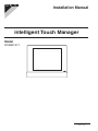
Installation Manual
intelligent Touch Manager
Model
DCM601A71
3P291714-2B
Disclosure
To the User in USA
Part 15 of FCC
Note: This equipment has been tested and found to comply with the limits for a Class B
digital device, pursuant to part 15 of the FCC Rules. These limits are designed to provide
reasonable protection against harmful interference in a residential installation. This equipment generates, uses and can radiate radio frequency energy and, if not installed and used
in accordance with the instructions, may cause harmful interference to radio communications. However, there is no guarantee that interference will not occur in a particular installation. If this equipment does cause harmful interference to radio or television reception,
which can be determined by turning the equipment off and on, the user is encouraged to
try to correct the interference by one or more of the following measures:
- Reorient or relocate the receiving antenna.
- Increase the separation between the equipment and receiver.
- Connect the equipment into an outlet on a circuit different from that to which the receiver
is connected.
- Consult the dealer or an experienced radio/TV technician for help.
FCC CAUTION
Changes or modifications not expressly approved by the party responsible for compliance
could void the user’s authority to operate the equipment.
To the User in CANADA
Canadian ICES-003
This Class B digital apparatus complies with Canadian ICES-003.
Cet appareil numérique de la classe B est conforme à la norme NMB-003 du Canada.
Safety Considerations
All phases of the field-installation, including, but not limited to, electrical, piping, safety, etc.
must be in accordance with manufacturer’s instructions and must comply with national,
state, provincial and local codes.
Read these SAFETY CONSIDERATIONS carefully before installing the controller.
After completing the installation, ensure that the controller operates properly during the
startup operation.
Train the customer to operate and maintain the controller. Inform customers that they
should store this Installation Manual with the User’s Manual for future reference.
Always use a licensed installer or contractor to install this product. Improper installation
can result in electrical shock, fire, or explosion.
Meanings of WARNING, CAUTION, and NOTE Symbols.
WARNING
CAUTION
NOTE
Indicates a potentially hazardous situation which, if not
avoided, could result in death or serious injury.
Indicates a potentially hazardous situation which, if not
avoided, may result in minor or moderate injury.
It may also be used to alert against unsafe practices.
Indicates situations that may result in equipment or property-damage accidents only.
WARNING
•• Only qualified personnel must carry out the installation work.
•• Consult your Daikin dealer regarding relocation and reinstallation of the controller.
Improper installation work may result in electric shocks or fire.
•• Install the controller in accordance with the instructions in the installation manual.
Improper installation may cause electrical shocks or fire.
•• Use only specified accessories and parts for installation work.
Failure to use specified parts may result in electric shocks, fire, or the unit falling.
•• Do not disassemble, reconstruct, or repair.
Electric shock or fire may occur.
•• Make sure that all wiring is secured, that specified wires are used, and that no
external forces act on the terminal connections or wires.
Improper connections or installation may result in fire.
•• Before touching electrical parts, turn off the unit.
English
Installation Manual 3P291714-2B
DCM601A71 intelligent Touch Manager
3
CAUTION
•• Keep water out of the controller.
•• To avoid electric shock due to entry of water or insects, fill the wiring throughhole with putty.
•• Do not wash the controller with water as it may result in electrical shocks or
fire.
•• Do not touch the controller buttons with wet fingers.
Touching the buttons with wet fingers can cause an electric shock.
•• Do not install the controller in the following locations:
(a) Where a mineral oil mist or oil spray or vapor is produced, for example, in a
kitchen.
Plastic parts may deteriorate and fall off.
(b) Where corrosive gas, such as sulfurous acid gas, is produced.
(c) Near machinery emitting electromagnetic waves.
Electromagnetic waves may disturb the operation of the control system and cause
the unit to malfunction.
(d) Where flammable gas may leak, where there is carbon fiber or ignitable dust
suspensions in the air, or where volatile flammables such as thinner or gasoline are handled.
Operating the unit in such conditions can cause a fire.
(e) High temperature area or directly flamed point.
Heating and/or fire can occur.
(f) Moist area, where there is exposure to water.
If water enters the inside of the controller, it may cause electric shock and electrical
components may fail.
NOTE
•• Install the control wires for the controller at least 3.5 feet (1 meter) away from
televisions or radios to prevent image interference or noise.
Depending on the radio waves, a distance of 3.5 feet (1 meter) may not be sufficient
to eliminate the noise.
4
Installation Manual 3P291714-2B
DCM601A71 intelligent Touch Manager
English
Contents
1
Before Installation .................................................................................................... 7
1.1
Checking that all accessories are included ................................................................................. 7
1.2
Understanding external dimensions ........................................................................................... 8
1.3
Understanding where terminals and switches are located ....................................................... 10
1.3.1 Rear face ........................................................................................................................ 10
1.3.2 Front panel ..................................................................................................................... 11
1.3.3 Side face ......................................................................................................................... 12
1.3.4 Wiring of cables .............................................................................................................. 12
1.4
Determining installation place ................................................................................................... 13
1.4.1 Installation place and mounting direction ....................................................................... 13
1.4.2 Environmental conditions ............................................................................................... 13
1.4.3 Required space .............................................................................................................. 13
2
Electric Wiring ......................................................................................................... 14
2.1
Removing wiring cover from rear face ...................................................................................... 14
2.2
Connecting DIII-NET-compatible air conditioning equipment ................................................... 14
2.2.1 Terminal location and schematic connection diagram .................................................... 15
2.2.2 Wiring specifications ....................................................................................................... 16
2.2.3 Precautions for using multiple centralized controllers ..................................................... 16
2.3
Connecting a LAN cable ........................................................................................................... 17
2.3.1 Terminal location and schematic connection diagram .................................................... 18
2.3.2 Wiring specifications ....................................................................................................... 18
2.4
Connecting I/O module ............................................................................................................. 19
2.4.1 Terminal location and schematic connection diagram .................................................... 19
2.4.2 Wiring specifications ....................................................................................................... 19
2.4.3 Address setup ................................................................................................................ 20
2.5
Connecting an emergency stop input device or power meter ................................................... 20
2.5.1 Terminal location and schematic connection diagram .................................................... 20
2.5.2 Wiring specifications ....................................................................................................... 21
2.6
Connecting iTM plus adaptors .................................................................................................. 21
2.6.1 Terminal location and schematic connection diagram .................................................... 22
2.6.2 Wiring specifications ....................................................................................................... 22
2.7
Connecting power supply ......................................................................................................... 23
2.7.1 Terminal location and schematic connection diagram .................................................... 23
2.7.2 Wiring specifications ....................................................................................................... 24
3
Secure installation of intelligent Touch Manager ................................................ 25
3.1
Wall mounting ........................................................................................................................... 25
3.1.1 Parts to be used ............................................................................................................. 25
3.1.2 Installation procedure ..................................................................................................... 26
English
Installation Manual 3P291714-2B
DCM601A71 intelligent Touch Manager
5
3.2
Flush wall mounting .................................................................................................................. 27
3.2.1 Parts to be used ............................................................................................................. 27
3.2.2 Wall opening dimensions ................................................................................................ 27
3.2.3 Installation procedure ..................................................................................................... 28
3.3
Mounting to control enclosure .................................................................................................. 30
3.3.1 Parts to be used ............................................................................................................. 30
3.3.2 Wall opening dimensions ................................................................................................ 30
3.3.3 Installation procedure ..................................................................................................... 30
4
Basic setup of intelligent Touch Manager ............................................................ 32
4.1
Setting backup battery to ON ................................................................................................... 32
4.2
Turning on power supply for intelligent Touch Manager and air conditioners ........................... 32
4.3
Setting up locale ....................................................................................................................... 33
4.4
Setting time zone ...................................................................................................................... 33
4.5
Setting current time and daylight saving time ........................................................................... 34
4.6
Confirming air conditioner auto registration results .................................................................. 34
4.7
Setting DIII-NET address for each air conditioner .................................................................... 35
4.7.1 Names of buttons and display areas .............................................................................. 35
4.7.2 Setting address with wired remote controller ................................................................. 36
4.7.3 Setting address with navigation remote controller .......................................................... 38
4.7.4 Setting an unique address to each unit (when Power Proportional Distribution (option) is used) .... 39
5
6
Quick Operation Guide .......................................................................................... 40
5.1
Viewing target area and management point information in list format ...................................... 40
5.2
Displaying areas and management points ................................................................................ 40
5.3
Starting/stopping an area or management point ...................................................................... 41
Installation Manual 3P291714-2B
DCM601A71 intelligent Touch Manager
English
1
Before Installation
Before you start installing the intelligent Touch Manager, perform the following preparatory
checks.
•• Check that the intelligent Touch Manager comes with all accessories.
•• Confirm where the terminals and switches of the intelligent Touch Manager are located.
•• Check that an appropriate space for installing the intelligent Touch Manager is available.
1.1
Checking that all accessories are included
Based on the following accessory list, check that all accessories for the intelligent Touch
Manager are included. If there is any missing or defective part, contact your DAIKIN dealer
where you purchased the product.
<Accessories included with intelligent Touch Manager>
A
B
D
d-1
d-2
E
e-1
a-1
b-1
b-2
b-3
e-2
C
F
f-1
c-1
c-2
c-3
c-4
f-2
A (a-1) intelligent Touch Manager body (1 pc.)
B Wall mounting parts
(b-1) Round-head wood screw (φ4.1×25), 4 pcs. (b-2) P-tight screw (φ3×8), 1 pc.
(b-3) Wall mounting metal plate, 1 pc.
C Flush wall mounting parts
(c-1) Flat-head screw (M4×40), 4 pcs. (c-2) Pan-head screw (M4×14, with spring
washer and plain washer), 4 pcs.
(c-3) Frame bracket, 1 pc. (c-4) Angle bracket, 2 pcs.
D Control enclosure securing parts
(d-1) Pan-head screw (M4×40, with spring washer and plain washer), 4 pcs.
(d-2) Nut (φ4), 4 pcs.
English
E
(e-1) Clamp, 1 pc. (e-2) Push mount tie, 3 pcs.
F
(f-1) Installation manual (This manual), 1 pc. (f-2) Paper template, 2 pcs.
Installation Manual 3P291714-2B
DCM601A71 intelligent Touch Manager
7
1.2
Understanding external dimensions
•• intelligent Touch Manager body
10-3/32
3/16
3/16
8-5/32
3/16
31/32
5-31/32
5/16
1-5/32
31/32
5/16
3/16
5/16
9-9/16
5/16
10-23/32
11-13/32
(in.)
•• Wall mounting metal plate
7-17/32
9-7/32
2-3/8
1-9/16
Thickness 1/32
8
Installation Manual 3P291714-2B
DCM601A71 intelligent Touch Manager
(in.)
English
•• Frame bracket
11-3/32
9-1/2
8-3/16
9-7/32
8-13/16
2-7/16
9/32
2
17/3
Φ1-
8-27/32
Thickness 1/16
(in.)
•• Angle bracket
1-1/8
9-29/32
8-13/16
8-5/16
4-13/32
15/32
25/32
1-23/32
Thickness 1/16
English
Installation Manual 3P291714-2B
DCM601A71 intelligent Touch Manager
(in.)
9
1.3
Understanding where terminals and switches are located
Understand the arrangement of terminals and the location of openings on the unit and
plan how to route the cable and in which order to connect its wires to facilitate the installation procedure. For connection details including the cable type and terminal size, refer to
“2. Electric Wiring”.
1.3.1
Rear face
Most terminals are located on the rear face of the intelligent Touch Manager. However,
they are covered with a terminal cover for safety reasons. Remove 2 screws to detach the
cover, and you can see various types of ports (terminals).
<Rear face of intelligent Touch Manager>
A [POWER] The power line connection terminals. A power supply voltage of 24 VAC (at
60 Hz) is required. Near the terminal block, there is a blue resin cable mount for
securing the power supply cable with the clamp.
B [DIII] The communication line connection terminals for “DIII-NET”, which enables
communications with DAIKIN’s air conditioning equipment.
C [LINE, PHONE] The port used when subscribing to the DAIKIN “Air Conditioning
Network Service System” online monitoring service for air-conditioning systems. To
use the “Air Conditioning Network Service System” service, you need to sign a separate maintenance contact.
D [RESERVE] No Use.
E
[RS-485] The terminals for connecting serial equipment.
F
[plus ADP IF] The terminals for connecting one or more iTM plus adaptors when the
intelligent Touch Manager is used to control more air conditioning devices.
G [Di (1-4), COM] The terminals for stopping air conditioners according to the external
signal in an emergency, for connecting a power meter to calculate the electricity
usage of individual air conditioners, or for other operations.
H [LAN] The port for connecting the intelligent Touch Manager to an Ethernet network.
10
Installation Manual 3P291714-2B
DCM601A71 intelligent Touch Manager
English
1.3.2
Front panel
Located below the monitor display on the front panel are four LEDs that indicate the operating status of the intelligent Touch Manager. Sliding the front slide cover down and then
removing a screwed cover reveals terminals used during the setup after installation or
during maintenance work.
<Front face of intelligent Touch Manager>
A [SERVICE LAN] The port for temporarily connecting the intelligent Touch Manager
to a LAN from its front face, instead of its rear face, during the operations such as
installation or maintenance.
B [LAN SW] This is for switching between the LAN port on the back and the SERVICE
LAN port on the front.
You cannot close the cover when the switch set to “FRONT”. To close the cover, select
“BACK”.
C [BACKUP] The switch for turning on/off the backup power supply for retaining the
current settings.
D [DIII MASTER] The switch for setting “MASTER” or “SLAVE” when there are multiple
DIII-NET centralized controllers such as intelligent Touch Manager.
E
[CPU ALIVE] LED (Green) The LED that indicates that the CPU is operating normally. The CPU is operating normally when this LED is blinking and malfunctioning
when it is on or off.
(It takes about 10 seconds for detection of the abnormality.)
On: Software error
Off: Hardware error or power off
F
[LAN LINK] LED (Green) The LED that indicates whether or not the hardware connection is established normally between the intelligent Touch Manager and the equipment connected to the LAN port. It is lit when there is no error.
G [DIII MONITOR] LED (Yellow) This LED blinks when data is sent or received via DIIINET communication line.
H [MONITOR] key and LED (Orange/Green) Each time you press this key, the monitor
display turns on/off. The color of the LED also changes simultaneously.
Off: The monitor is powered off.
On (Orange): The monitor display is off.
On (Green): The monitor display is on.
I
English
[RESET//] The switch for restarting the intelligent Touch Manager.
Installation Manual 3P291714-2B
DCM601A71 intelligent Touch Manager
11
1.3.3
Side face
On the left side of the intelligent Touch Manager, there is a USB port. The USB port is used
for making settings, performing maintenance or other operations after the installation of
the intelligent Touch Manager is completed. Also, on this side a label is attached on which
the information such as product name, weight, power supply and serial number are
printed.
<Side face of intelligent Touch Manager>
[ ] Open this cover to connect the memory to the USB port. This port can be turned 90
degrees to the front direction. You can connect to this port from the front direction if there
is not enough space on the side.
1.3.4
Wiring of cables
To flush-mount the intelligent Touch Manager to the wall, you need to route in advance the
cables through the cable hole of the frame bracket.
The following pictorial wiring diagram (example) shows the state after connections to the
intelligent Touch Manager rear face are completed.
<Pictorial cable wiring diagram (example)>
B
A
A Push mount tie
B Clamp
C
C To conduit tube
Be sure to fix all cables using the supplied push mount ties.
Fix the power supply cable to the blue resin cable mount using the white clamp, then tie
the cable and other cables with the black push mount tie, as shown in the cable wiring
diagram (example).
When using the black push mount tie, pass its tale through its hole to tie the cables.
12
Installation Manual 3P291714-2B
DCM601A71 intelligent Touch Manager
English
1.4
Determining installation place
Be sure to install the intelligent Touch Manager in a place that meets the conditions
described in 1.4.1 to 1.4.3.
1.4.1
Installation place and mounting direction
Below are the description of the installation place and mounting direction. Be sure to
confirm.
•• Installation place: Indoor, free from dust and water splashes
(For details, refer to CAUTION in the section of Safety Considerations.)
•• Mounting direction: Vertical only.
1.4.2
Environmental conditions
Check that the installation environment meets the following conditions.
•• The ambient temperature : 32 to 104 °F.
•• The ambient humidity : 85% RH or less (without condensation).
•• The electromagnetic wave does not affect the operation of the intelligent Touch Manager.
1.4.3
Required space
The figure shown below indicates the space required for installation. The following conditions must be met. Make sure that there is a minimum clearance of 1-3/16 in. from the top
edge, 3-15/16 in. from the left side edge, 1-3/16 in. from the right side edge, and 2-3/8 in.
from the bottom edge of the unit.
<Installation space required for intelligent Touch Manager>
Required installation space
A
1-3/16
3-15/16
1-3/16
3-15/16
9-9/16
MONITOR
MONITOR
MONITOR
MONITOR
11-13/32
2-3/8
B
2-3/8
(in.)
A Top
B Wall
English
Installation Manual 3P291714-2B
DCM601A71 intelligent Touch Manager
13
2
Electric Wiring
This chapter describes the procedure for connecting the intelligent Touch Manager with
DAIKIN air conditioning devices and other equipment.
In addition to air conditioners, the intelligent Touch Manager can monitor and control a
wide range of equipment. However, the required connection procedures vary depending
on the equipment to be connected.
Do not connect more than two wires to the same terminal.
Required procedures
•• 2.2 Connecting DIII-NET-compatible air conditioning equipment
Equipment-specific procedures
•• 2.3 Connecting a LAN cable
•• 2.7 Connecting power supply
•• 2.4 Connecting I/O module
•• 2.5 Connecting an emergency stop input device or power meter
•• 2.6 Connecting iTM plus adaptors
WARNING
•• Do not turn on the power supply before all wire connections are completed.
When there is an earth leakage breaker or a local switch installed on the circuit,
make sure that the circuit is securely interrupted. Otherwise, an electric shock
may result.
•• After the wiring is completed, double-check that all wires are connected correctly before turning on the power supply.
•• All field supplied parts and materials, electric works must conform to local codes.
•• All wiring must be performed by an authorized electrician.
2.1
Removing wiring cover from rear face
<Removing wiring cover>
Remove the wiring cover from the rear face. Take out
two screws using a Phillips screwdriver to remove
the wiring cover.
2.2
Connecting DIII-NET-compatible air conditioning equipment
DIII-NET is the DAIKIN’s original communication method used between air conditioners.
Using DIII-NET, you can centrally control multiple DAIKIN DIII-NET-compatible air conditioning devices by connecting them to your intelligent Touch Manager.
WARNING
•• Be sure to perform the operation during power-off conditions. Not doing so
may cause an electric shock.
•• The maximum length of adhered wiring of high current electrical line of power
wires and weak current line of communication wires must be kept to 65 ft. or less.
14
Installation Manual 3P291714-2B
DCM601A71 intelligent Touch Manager
English
2.2.1
Terminal location and schematic connection diagram
To connect the DIII-NET communication line, use F1 and F2 terminals that are located on
the rear face and indicated with “DIII” mark. These 2 terminals have no polarity. An example of connecting more than two air conditioning devices is shown in the following conceptual connection diagram.
CAUTION
Make sure that the wires you are connecting to the F1 and F2 terminals are not
power wires. Inadvertently connecting power wires to these terminals results in
a failure of the air conditioner or intelligent Touch Manager.
<Conceptual connection diagram with air conditioning equipment>
N, P
N, P
N, P
N, P
N, P
N, P
N, P
N, P
N, P
N, P
A Outdoor unit
B OUT - OUT communication (terminal)
C IN - OUT communication (terminal)
D Indoor unit
English
E
A maximum of 16 indoor units can be connected per remote controller group.
F
A maximum of 64 remote controller groups (128 indoor units) can be connected.
When the power proportional distributions is applied, the maximum number of indoor
units is 64.
Installation Manual 3P291714-2B
DCM601A71 intelligent Touch Manager
15
NOTE
•• What’s a remote controller group?
A single remote controller can simultaneously control a maximum of 16 indoor units.
This capability is referred to as group control. A remote controller group is a group of
indoor units controlled under the same remote controller.
[Schematic diagram of remote controller group]
A
F1, F2
N, P
F1, F2
N, P
F1, F2
N, P
F1, F2
N, P
A Max.16 Indoor units
2.2.2
Wiring specifications
•• Cable type: 2-core vinyl-insulated vinyl-sheathed cable/vinyl cabtyre cable or 2-core
shielded cable
•• Core thickness: AWG 18-16
•• Terminal treatment: Use a round crimp-type terminal (M3.5) with insulating sleeve
CAUTION
•• Do not use multicore cables with three or more cores.
•• When using a shielded cable, connect only one end of the cable to the ground.
•• The maximum wiring length is 3280 ft. and total wiring length is 6561 ft. or less.
When using a shielded wire, the total wiring length is limited to 4921 ft. or less.
2.2.3
Precautions for using multiple centralized controllers
The “centralized controller” refers to the equipment (e.g. the intelligent Touch Manager)
that controls multiple air conditioners. Besides the intelligent Touch Manager, the DAIKIN’s
product portfolio includes a wide range of centralized controllers suitable for different
applications or building sizes, which can be used in combination to construct an optimal
air conditioning control system.
If multiple centralized controllers are connected on the DIII-NET network, you must set
MASTER and SLAVE relationship for those controllers.
Assign only one of those controllers to MASTER, and other controllers to SLAVE.
The intelligent Touch Manager is set to MASTER by default. Change the setting to SLAVE
in any of the following cases:
•• Where Interface for use in BACnet is installed in parallel.
•• Where Interface for use in LONWORKS is installed in parallel.
•• If there is another intelligent Touch Manager or iTM plus adaptor which is assigned to
MASTER.
16
Installation Manual 3P291714-2B
DCM601A71 intelligent Touch Manager
English
<DIII MASTER>
To change the setting of the intelligent Touch Manager to SLAVE, turn the DIII MASTER switch located
under the front slide cover. Placing the DIII MASTER
switch in the upper position (labeled as “SLAVE”)
changes it to a SLAVE.
When installing multiple centralized controllers, set only the highest-priority controller to
MASTER and all other controllers to SLAVE according to the following order of priority.
(1) Interface for use in BACnet
(2) Interface for use in LONWORKS
(3) intelligent Touch Manager (Main), iTM plus adaptor (Main)
(4) Central Remote Controller (Main)
(5) intelligent Touch Manager (Sub), iTM plus adaptor (Sub)
(6) Central Remote Controller (Sub)
(7) ON/OFF Controller (Main)
(8) ON/OFF Controller (Sub)
High
Priority
Low
Centralized controllers that cannot be connected to the same network as the intelligent Touch Manager.
•• CALCULATE UNIT
•• intelligent Processing Unit
•• Parallel Interface
•• intelligent Touch Controller
•• DIII-NET Plus Adapter
•• Residential Central Remote Controller
•• Schedule Timer
•• Wiring Adaptor for Electrical Appendices (1) (KRP2)
2.3
Connecting a LAN cable
By connecting the intelligent Touch Manager with a PC via Ethernet, you can remotely
perform operations such as operation setup and maintenance of air conditioning system.
WARNING
Do not clamp the LAN cable with high current cables.
NOTE
For how to connect the intelligent Touch Manager to a PC network, contact your network administrator.
English
Installation Manual 3P291714-2B
DCM601A71 intelligent Touch Manager
17
2.3.1
Terminal location and schematic connection diagram
Using a LAN cable, connect the LAN port to the network hub.
<LAN connection schematic diagram>
A Rear face of intelligent Touch Manager
B LAN cable
C Hub
D PC
2.3.2
Wiring specifications
•• Applicable cable standard: 100Base-TX or 10Base-T
•• Connector standard: RJ-45
<SERVICE LAN socket and LAN SW
switch>
NOTE
•• When you connect the intelligent Touch Manager to the LAN temporarily during installation
or maintenance, use the SERVICE LAN port
located on the front face.
The SERVICE LAN port is enabled by changing the position of the LAN SW switch beside
the SERVICE LAN to the FRONT position.
•• You cannot close the cover when the switch
set to “FRONT”. To close the cover, select
“BACK”.
A SERVICE LAN
B LAN SW
18
Installation Manual 3P291714-2B
DCM601A71 intelligent Touch Manager
English
2.4
Connecting I/O module
In combination with the I/O module, the intelligent Touch Manager can monitor and control
a maximum of 960 contacts of non-DAIKIN peripheral devices such as lighting equipment
and security systems. Connect the intelligent Touch Manager to the termination of the
RS-485 wiring.
WARNING
•• Be sure to perform the operation during power-off conditions. Not doing so
may cause an electric shock.
•• Do not clamp the cables with high-current lines such as a power cable.
2.4.1
Terminal location and schematic connection diagram
<Schematic drawing of I/O module connection>
RS-485
MONITOR
Wattmeter
Lighting
The number of contacts per node
is up to 120. The maximum
number of nodes is 30.
Fan
Connect to the RS-485 terminals located on the rear face. As the terminals have polarity,
be sure to connect the positive core wire to the + (positive) terminal and the negative core
wire to the – (negative) terminal, respectively.
2.4.2
Wiring specifications
•• Cable type: CPEV or FCPEV cable (shielded type also acceptable)
•• Cable length: 1640 ft. or less
•• Core thickness: AWG 22-19
CAUTION
When using a shielded cable, be sure to connect the cable to the G (ground)
terminal.
English
Installation Manual 3P291714-2B
DCM601A71 intelligent Touch Manager
19
2.4.3
Address setup
<Bus coupler>
The bus coupler located at the left end of nodes has
rotary switches for setting the addresses.
Set a unique address for each node.
For details, refer to the “Commissioning Manual
Supplementary Volume (External Management Points
(EM11A026))”.
2.5
Connecting an emergency stop input device or power meter
The intelligent Touch Manager can perform operations such as an emergency stop of air
conditioners according to the external signal input device, and an electricity usage calculation for each air conditioner (for power proportional distribution) according to the pulse
inputs from a power meter.
WARNING
•• Be sure to perform the operation during power-off conditions. Not doing so
may cause an electric shock.
•• Do not clamp high-current cables together with low-current cables.
2.5.1
Terminal location and schematic connection diagram
Connect the contact input signal wire or pulse signal wire to Di1, Di2, Di3, Di4, or COM
terminal on the orange connector on the rear face. Each of these terminals has different
function.
[Di1] Emergency stop input
[Di2] [Di3] [Di4] Pulse input, contact signal input
[COM] Common
However, the function settings for these terminals can be changed later. For how to change
the function settings, refer to the “Commissioning Manual (EM11A022)”.
<Schematic drawing of Di connection>
NOTE
The COM terminals are all connected internally.
So, you can use either of them. However, you
can connect up to two wires simultaneously to
each COM terminal. When using an open collector type output, connect the COM terminal to
the negative side.
20
Installation Manual 3P291714-2B
DCM601A71 intelligent Touch Manager
Di1
Di3
COM COM
Di2
Di4
COM COM
English
2.5.2
Wiring specifications
•• Cable type: CPEV cable
•• Core thickness: AWG 22-19
•• Cable length: 656 ft. or less
<Pulse width>
A
B
A Pulse width: 20 to 400 ms
B Pulse interval: 100 ms or more
CAUTION
•• The contact connected to the contact input terminal must be capable of handling 10 mA at 16 VDC.
•• If an instantaneous contact is used for triggering an emergency stop, use one
that has an energization time of 200 ms or more.
NOTE
Once the emergency stop input signal is turned on, all air conditioners stop and do not
restart until the emergency stop input is cleared. When the manual reset is specified for
the resetting method, you need to clear the emergency stop using the intelligent Touch
Manager.
2.6
Connecting iTM plus adaptors
If you have many air conditioners, use iTM plus adaptors to connect them. It is a fact that
the number of indoor groups you can control using a single intelligent Touch Manager is
limited to 64. By using iTM plus adaptors, you can add 64 indoor unit groups per iTM plus
adaptor. Moreover, considering that the intelligent Touch Manager can be connected with
a maximum of seven iTM plus adaptors, you can control a total of 512 groups of indoor
units at a maximum using a single intelligent Touch Manager.
WARNING
•• Be sure to perform the operation during power-off conditions. Not doing so
may cause an electric shock.
•• Do not clamp high-current cables together with low-current cables.
English
Installation Manual 3P291714-2B
DCM601A71 intelligent Touch Manager
21
2.6.1
Terminal location and schematic connection diagram
Connect the iTM plus adaptor to the plus ADP IF terminal located on the rear face. Connect the intelligent Touch Manager to the plus ADP IF terminal. As the terminals have
polarity, be sure to connect the positive wire to the “+” terminal and the negative wire to
the “–” terminal without fail. Connect the intelligent Touch Manager to the termination of
the RS-485 wiring.
<Terminal location and schematic connection diagram>
A intelligent Touch Manager
B iTM plus adaptor
C plus ADP IF (intelligent Touch Manager)
D plus ADP IF (iTM plus adaptor)
E
2.6.2
iTM plus adaptor on which termination resistor must be enabled
(For details, refer to the “iTM plus adaptor installation manual” (EM11A030).)
Wiring specifications
•• Cable type: CPEV or FCPEV cable
•• Core thickness: AWG 22-19
•• Cable length: The overall cable length between the intelligent Touch Manager and the
terminal iTM plus adaptor is 164 ft. or less.
•• Wiring connection type: Sequential connections
NOTE
Each air conditioner controlled via an iTM plus adaptor is also assigned a DIII address
between “1-00” to “4-15”. From the intelligent Touch Manager, it is recognized as “2:100”, “3:1-02”, or the like, with the DIII-NET port number prefixed.
22
Installation Manual 3P291714-2B
DCM601A71 intelligent Touch Manager
English
2.7
Connecting power supply
Connect the intelligent Touch Manager to an power supply.
WARNING
Be sure to perform the operation during power-off conditions. Do not turn the
power supply on until all connections are made. Not doing so may cause an
electric shock.
2.7.1
Terminal location and schematic connection diagram
<Schematic power connection diagram>
Connect the power supply to the three terminals, L
(Live), N (Neutral), and ground in the POWER section.
A Earth
B Earth leakage breaker
C Power supply 24VAC 60 Hz
English
Installation Manual 3P291714-2B
DCM601A71 intelligent Touch Manager
23
2.7.2
Wiring specifications
•• Cable type: Ordinary tough rubber sheathed cord (60245 IEC 53) equivalent or higher
Ordinary polyvinyl chloride sheathed cord (60227 IEC 53) equivalent or higher
•• Core thickness: P
ower wire: AWG 17-14
Earth lead: Size must comply with local codes.
•• Terminal treatment: Use a round crimp-type terminal (M4) with insulating sleeve.
•• Power supply voltage: Single phase 24 VAC (at 60 Hz)
•• Voltage fluctuation: ±10% or less
•• Electric power consumption: 23 W
CAUTION
•• An earth leakage breaker capable of shutting down power supply to the entire
system must be installed.
•• Turning on/off the earth leakage breaker turns on/off the power supply to the
intelligent Touch Manager.
•• When using an earth leakage breaker, make sure to select one useful for to
protection against overcurrent and short-circuit. When using an earth leakage
breaker only for earth device, make sure to use a wiring interrupter together.
•• The power supply requires earth leakage breaker installation and earth wire
connection. After installing an earth leakage breaker, be sure to connect only
the intelligent Touch Manager to it.
•• To prevent accidents due to wire breakage or disconnection, secure the power
supply cables to the blue resin cable mount with cable ties.
•• Be sure to connect the earth wire.
•• Do not connect the earth wire to gas or water pipes, lighting rod, or telephone
earth wire.
•• Replace the unit when the unit cannot be turned on due to the blowing of the
electrical fuse.
24
Installation Manual 3P291714-2B
DCM601A71 intelligent Touch Manager
English
3
Secure installation of intelligent Touch Manager
There are the following three ways to install the intelligent Touch Manager.
•• Wall mounting: Fix the intelligent Touch Manager to the metal plate which is attached to
the wall.
•• Flush wall mounting: Embed the back of the intelligent Touch Manager into the wall
using the frame bracket and angle brackets.
•• Direct mounting to control enclosure: Fix the intelligent Touch Manager directly to the
control enclosure using screws only (with no brackets).
<Ways of installation>
Wall mounting
3.1
Wall mounting
3.1.1
Parts to be used
Flush wall mounting
Direct mounting to control enclosure
To wall-mount the intelligent Touch Manager, use the following accessory mounting parts:
•• Wall mounting metal plate, 1 pc.
•• Round-head wood screw (φ4.1×25), 4 pcs.
•• P-tight screw (φ3×8), 1 pc.
(Check that there are all accessories listed in section 1.1: see the accessories included
with intelligent Touch Manager B.)
English
Installation Manual 3P291714-2B
DCM601A71 intelligent Touch Manager
25
3.1.2
Installation procedure
CAUTION
•• The wall mounting metal plate has a number of holes for attaching the roundhead wood screws. Though you can use any of these holes to fix the plate, we
recommend you to use ones closer to the edge in order to prevent wobbling.
•• Secure the round-head wood screws at four points.
<Wall mounting installation>
A
C
D
C
C
C
MO
NI
TO
R
B
NOTE
•• How to use the P-tight screw
Screw in from the bottom of the intelligent Touch Manager.
Remove the rear cover before starting installation.
E
B
D
A Wall
B P-tight screw
C Round-head wood screw
D Wall mounting metal plate
E
26
intelligent Touch Manager
Installation Manual 3P291714-2B
DCM601A71 intelligent Touch Manager
English
3.2
Flush wall mounting
3.2.1
Parts to be used
To flush-mount the intelligent Touch Manager to the wall, use the following accessory
mounting parts:
•• Frame bracket, 1 pc.
•• Angle bracket, 2 pcs.
•• Flat-head screw (M4×40), 4 pcs.
•• Pan-head screw (M4×14, with spring washer and plain washer), 4 pcs.
(Check that there are all accessories listed in section 1.1: see the accessories included
with intelligent Touch Manager C.)
3.2.2
Wall opening dimensions
Use the following dimensional drawing to provide a sufficient opening.
NOTE
•• The supplied paper template helps you mark the dimensions of the required wall
opening.
•• Use the supplied paper template (Flush wall mounting).
<Wall opening dimensions for flush wall mounting>
10-5/32
4
B
A
8-13/16
8-5/16
E
C
D
9-1/2
(in.)
A Inner wall material
B Beams of building (frame)
C intelligent Touch Manager
D 2-3/8 in. min.
E
English
Opening
Installation Manual 3P291714-2B
DCM601A71 intelligent Touch Manager
27
3.2.3
Installation procedure
1. Insert the mounting frame bracket and angle brackets into the wall opening and secure
them to the wall in such a manner that the wall is sandwiched between the brackets
with flat-head screws.
NOTE
•• You need to route in advance the cables connected to the rear face of the intelligent
Touch Manager through the cable hole provided at the bottom of the frame bracket.
•• Install the rear face terminal cover while the intelligent Touch Manager is removed.
<Securing frame bracket and angle brackets>
A
D
B
C
B
B
B
A Wall
B Flat-head screw
C Frame bracket
D Angle bracket
NOTE
When securing the frame bracket, be careful not to drop the angle brackets inside the
wall.
2. Remove the front panel from the front face of the intelligent Touch Manager. The front
panel is originally attached to the monitor screen.
28
Installation Manual 3P291714-2B
DCM601A71 intelligent Touch Manager
English
<Removing front panel>
B
A
MO
NIT
OR
A Front panel
B Main body
3. Insert the intelligent Touch Manager into the frame bracket attached to the wall and fix
the intelligent Touch Manager to the frame bracket using four screw holes around the
monitor screen and the pan-head screws.
<Installing intelligent Touch Manager body>
A
A
A
A
A Pan-head screw
4. Attach the front panel of the intelligent Touch Manager back to its original position.
English
Installation Manual 3P291714-2B
DCM601A71 intelligent Touch Manager
29
3.3
Mounting to control enclosure
3.3.1
Parts to be used
To mount the intelligent Touch Manager directly to the control enclosure, use the following
accessory mounting parts:
•• Pan-head screw (M4×40, with spring washer and plain washer), 4 pcs.
•• Nut (φ4), 4 pcs.
3.3.2
Wall opening dimensions
Use the following dimensional drawing to provide a sufficient opening.
NOTE
•• The supplied paper template helps you mark the dimensions of the required wall
opening.
•• Use the supplied paper template (Direct mounting to control enclosure).
<Wall opening dimensions for direct mounting to control enclosure>
10-1/8
B
A
4
3-5/8
E
8-5/32
2-3/8
C
10-23/32
D
(in.)
A Control enclosure face plate
B Control enclosure bottom board
C intelligent Touch Manager
D 31/32 in. min.
E
3.3.3
Opening
Installation procedure
1. Remove the front panel of the intelligent Touch Manager, referring to Removing front
panel in section 3.2.3 Installation procedure.
This frame is snapped into the edge of the monitor display.
You can remove it by hand as it is not screwed.
After removing the front panel, the four holes (two holes on each right/left side) appears
around the monitor screen.
2. Insert the intelligent Touch Manager into the opening of the control enclosure and
install it to the control enclosure using the pan-head screws.
3. Attach the front panel of the intelligent Touch Manager back to its original position.
30
Installation Manual 3P291714-2B
DCM601A71 intelligent Touch Manager
English
<Installing intelligent Touch Manager body to control enclosure>
B
B
B
A
B
A
A
MO
NIT
OR
A
A Pan-head screw
B Nut
CAUTION
If the intelligent Touch Manager is directly mounted to the control enclosure, you
will be exposed to the power line connection terminals when opening the control
enclosure door.
Touching electrical junctions by hand may result in an electric shock. Attach the
terminal cover to the rear face for your safety.
A
B
C
A Terminal cover
B Control enclosure
C intelligent Touch Manager
English
Installation Manual 3P291714-2B
DCM601A71 intelligent Touch Manager
31
4
Basic setup of intelligent Touch Manager
After checking that all connections are completed, start the intelligent Touch Manager
basic setup. The basic setup refers to the preparative settings for monitoring and controlling the air conditioning system using the intelligent Touch Manager.
Make each setting by following the guidance displayed on the screen after you turn on the
power supply of the intelligent Touch Manager.
The setting assignment made through this procedure may be changed at a later time.
4.1
Setting backup battery to ON
To retain the settings even in the event of a power outage, the intelligent Touch Manager
has a built-in battery. This battery is disabled by default. So first you need to change the
battery setting to ON.
< BACKUP switch >
1. Open the front slide cover. Take out screws using
a Phillips screwdriver to remove the front switch
cover.
2. Turn ON the BACKUP switch and attach the front
switch cover back to its original position. If the
power supply is left off for a long period of time
(six months or more), turn OFF the BACKUP
switch.
4.2
Turning on power supply for intelligent Touch Manager and
air conditioners
Turn on the power supply for the intelligent Touch Manager and devices that are connected to the intelligent Touch Manager.
1. First turn on the power supply for the air conditioners, and then for intelligent Touch
Manager. The Title screen appears and, after a while, the message “Ready to set up
A/C centralized address” appears.
Set the DIII-NET addresses using the remote controller of the air conditioner. For
details, refer to section 4.7 Setting DIII-NET address for each air conditioner.
2. Touch Close.
The Locale Settings screen appears.
CAUTION
Before turning on the power supply, double-check that all installations and connections are completed correctly.
NOTE
The message “Turn ON Battery Backup switch” may be displayed instead of the Locale
Setting screen. This message is displayed if you do not turn ON the data backup battery
switch in the step 4.1. If the message is displayed, make the setting according to section 4.1 Setting backup battery to ON. When done, touch the OK button shown with the
message on the screen. Then, the Locale setup screen appears.
32
Installation Manual 3P291714-2B
DCM601A71 intelligent Touch Manager
English
4.3
Setting up locale
Set the display type of date/time, unit of temperature, decimal point type, etc.
<Locale Settings screen>
1. [LOCALE] Set the following items on the screen.
[Date] Select the date display format.
[Time] Select the time display format (24-hour or 12-hour clock).
[Celsius / Fahrenheit] Select the temperature display unit (Celsius or Fahrenheit).
[Decimal point / CSV separate] Select the marks used as the decimal point and CSV
separator. For details, refer to the “User’s Manual (EM11A017)”.
[Icon Color] Select the icon color.
2. When setup is done, touch OK.
The Time Zone Settings screen appears.
4.4
Setting time zone
Set up the local standard time zone you want to use for the system clock.
<Time Zone Settings screen>
1. On the Time Zone Settings screen, select the time zone of desired region from the list
box.
2. Touch OK.
The Time/DST Setup screen appears.
English
Installation Manual 3P291714-2B
DCM601A71 intelligent Touch Manager
33
4.5
Setting current time and daylight saving time
Adjust the clock and set up the daylight saving time schedule.
<Time/DST Setup screen>
1. On the Time/DST Setup screen, set up the date/time and the daylight saving time
schedule. (Enable or disable the daylight saving time function. If enabled, select the
start time and the end time.)
2. Touch OK.
The A/C Auto Register screen appears.
4.6
Confirming air conditioner auto registration results
On the A/C Auto Register screen, the message “Below connected A/C units are found. Do
you want to register into Management Points? Reboot after registering ∙∙∙” appears.
1. Check that the number of all air conditioners that are set in section 4.7 Setting DIIINET address for each air conditioner is correctly displayed.
If you see any problem, touch the Refresh button to reload the up to data information,
or review the DIII address settings.
2. When the confirmation dialog appears, touch Yes.
The intelligent Touch Manager restarts and Main screen appears. The intelligent Touch
Manager setup has now been completed.
NOTE
When iTM plus adaptor is connected, power on the iTM plus adaptor in advance.
34
Installation Manual 3P291714-2B
DCM601A71 intelligent Touch Manager
English
4.7
Setting DIII-NET address for each air conditioner
The DIII-NET system has the control address used to identify each air conditioner group.
This is called “DIII-NET address”. You must set the DIII-NET address manually using the
remote controller of air conditioner. There are several types of the remote controller, and
the setting method differs depending on the controller type. This section describes commonly used two types of remote controllers, wired and navigation remote controllers, as
examples.
NOTE
For how to set the address for the Ventilator (Heat Reclaim Ventilator) or different adapters (such as a universal adapter), refer to the manuals supplied with those devices.
4.7.1
Names of buttons and display areas
The followings are the names of buttons and display areas of the wired remote controller.
<Wired Remote Controller>
A Address display area
B Parameter number display area
C Programming time buttons
A
D Temperature setting buttons
E
SCHEDULE button
F
Inspection / Test operation button
B
C
D
E
F
The followings are the names of buttons and display area of the navigation remote controller.
<Navigation Remote controller>
A Liquid-crystal display (with backlight)
B Up button
C Menu / OK button
D Right button
E
Cancel button
A
B
F
Down button
C
D
E
F
English
Installation Manual 3P291714-2B
DCM601A71 intelligent Touch Manager
35
4.7.2
Setting address with wired remote controller
The operation procedure of the wired remote controller is as follows.
NOTE
After power-on, the controller shows the symbol “88” for about 1 minute after displaying
all information on its display. During this period, it may not accept your operation. If so,
try operating the remote controller again after “88” disappears.
1. Press and hold the Inspection/Test Operation button for 4 seconds or more.
<Step 1>
F
HH
2. “SETTING” appears in the center of remote controller display. Using the Temperature Setting buttons, change the value shown in the parameter number display area to “00”. In the address display area, the current address setting is displayed. (This area will
show “–” if no address is set.)
<Step 2>
GROUP
SETTING
NOTE
The parameter number cannot be changed to “00” when the intelligent Touch Manager
is not powered on.
Power on the intelligent Touch Manager and wait for a while before trying to operate the
remote controller. You cannot change the parameter number to “00” also when the intelligent Touch Manager is not communicating with the indoor units normally. Check that
the cables are connected correctly.
3. Press the SCHEDULE button to make the “GROUP” indicator blink.
You are now ready to change the DIII-NET address.
<Step 3>
GROUP
36
SETTING
Installation Manual 3P291714-2B
DCM601A71 intelligent Touch Manager
English
4. Using the Programming time buttons, select the address you want to set.
<Step 4>
GROUP
SETTING
5. Press the SCHEDULE button to make the “GROUP” indicator stay lit.
The DIII-NET address has been set.
<Step 5>
GROUP
SETTING
6. Press the Inspection/Test Operation button.
You are now brought back to the screen shown in Step 6-2.
<Step 6-1>
GROUP
SETTING
<Step 6-2>
F
English
HH
Installation Manual 3P291714-2B
DCM601A71 intelligent Touch Manager
37
4.7.3
Setting address with navigation remote controller
The operation procedure of the navigation remote controller is as follows.
NOTE
You cannot perform the following procedure when the display backlight is off. In this
case, press any key to turn on the backlight before starting the procedure.
1. Press and hold the Cancel button for 4 seconds or more.
The “Service setting” menu is displayed.
<Step 1>
Cool
Thu
5 31 P
Room
Set to
82 F
78 F
2. Using the Up/Down buttons, select “Group Address” and press the Menu/OK button.
The “Group Address” menu is displayed.
<Step 2>
Ser vice Settings
2/3
Group Address
Indoor unit AirNet Address
Error Histor y
Indoor Unit Status
Outdoor Unit Status
Forced Fan ON
Setting
NOTE
The “Group Address” menu is not displayed when the intelligent Touch Manager is not
powered on. Power on the intelligent Touch Manager and wait for a while before trying
to operate the remote controller. The “Group Address” menu is not displayed also when
the intelligent Touch Manager is not communicating with the indoor units normally.
Check that the cables are connected correctly.
3. Using the Up/Down buttons, select “Group Address (Group)” and press the Menu/OK button.
The current address setting is displayed.
<Step 3>
Group Address
Group Address (Group)
Group Address (Unit)
Setting
4. Press the Menu/OK button to release the current address setting.
The mode indication changes from “Set” to “Release”. You are now ready to change the
DIII-NET address.
<Step 4>
Group Address (Group)
Gr Addr.
Set
1-00
Release
38
Installation Manual 3P291714-2B
DCM601A71 intelligent Touch Manager
English
5. Using the Up/Down buttons, select the address you want to set.
<Step 5>
Group Address (Group)
Gr Addr.
Release
1-00
Change
6. Press the Menu/OK button.
The indication changes from “Release” to “Set” and the DIII-NET address is set.
<Step 6>
Group Address (Group)
Gr Addr.
Set
1-03
Release
7. Press the Cancel button three times. You are now brought back to the screen shown in
Step 7-2.
<Step 7-1>
Group Address (Group)
Gr Addr.
Set
1-03
Release
<Step 7-2>
Cool
Thu
5 35 P
Room
Set to
82 F
4.7.4
86 F
Setting an unique address to each unit (when Power Proportional Distribution (option) is used)
When power distribution is enabled, you need to set a unique address for each unit. For
how to set an address, refer to the “Commissioning Manual Supplementary Volume (Power
Proportional Distribution (EM11A027))”.
English
Installation Manual 3P291714-2B
DCM601A71 intelligent Touch Manager
39
5
Quick Operation Guide
This chapter describes how to start/stop the areas and management points registered
with the intelligent Touch Manager and display their information quickly. For detailed operation procedures, refer to the “User’s Manual (EM11A017)”.
5.1
Viewing target area and management point information in
list format
C
A
A
List
B
C
Icon
A Touch the List button.
B The screen changes to the list view, where selecting “Indoor” in the Type combo box
causes the name, operation mode, setpoint, and fan speed of all areas and indoor
units to be listed.
C Touch the Icon button to return the Icon view screen.
5.2
Displaying areas and management points
A
B
C
B
Down
C
Up
A The level of the current area and management point is displayed.
B Touch the Down button to go to the area being selected and view the areas and
management points in it.
C Touch the Up button to go to the area one level above the current area.
40
Installation Manual 3P291714-2B
DCM601A71 intelligent Touch Manager
English
5.3
Starting/stopping an area or management point
B
A
B
On
A Select the area or management point you want to start or stop.
B Select Start or Stop in the On/Off buttons. When operation is started, the icon color
changes to green or red (depending on the system setting). When operation is
stopped, the color changes to grey.
English
Installation Manual 3P291714-2B
DCM601A71 intelligent Touch Manager
41
3P291714-2B EM11A018A (1306) HT