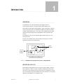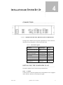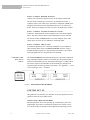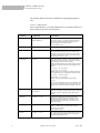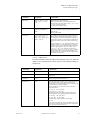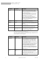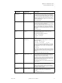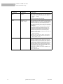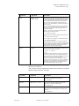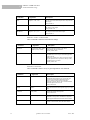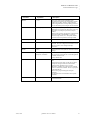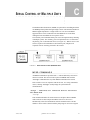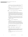
1
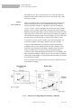
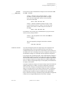
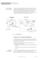
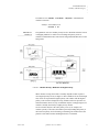
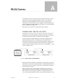
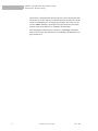
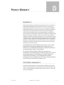
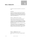
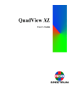
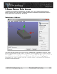
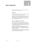
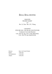
QuadView Plus
Video Windowing System
User Manual
e-mail: [email protected]
tel: 08-52 400 700 fax: 08-520 18121
RGB Spectrum
950 Marina Village Pkwy.
Alameda, CA 94501
P/N 350-7313
June 6, 2002
QuadView Plus User Manual
June 6, 2002
TABLE OF CONTENTS
Chapter 1
Introduction
1
General
Window Inputs
Output
Control of the QuadView Plus
System Features
Chapter 2
Supplied Components
5
Standard Supplied Components
Optional Items
Chapter 3
System Basics
7
Serial Control of the QuadView Plus
Windows
Selecting and Displaying Windows
Visibility of Window Imagery
Chapter 4
Installation and System Set Up
Connectors
Installing the QuadView Plus
System Set Up
Chapter 5
Serial Command Set
17
General
Serial Command Set Usage
Control Software For Windows
Chapter 6
Technical Specifications
Chapter 7
Troubleshooting
31
Troubleshooting Guide
How to Contact RGB Spectrum
Firmware Updates/README Files
Appendix A
RS-232 Control
33
Connecting the RS-232 Port
29
13
Appendix B
Updating System Firmware
37
Appendix C
Serial Control of Multiple Units
39
MPSD Commands
MPSD Example: Baud Rate Change
Appendix D
Product Warranty
43
Warranty
Extended Warranty
QuadView Plus User Manual
June 6, 2002
1
I NTRODUCTION
.....
................................ .
GENERAL
................................................
The QuadView Plus video windowing system displays four live
video/computer windows on a high-resolution, RGB display device.
Each channel accepts high-resolution RGB, Y PB PR Component, composite
video, and S-Video sources for simultaneous display in windows on a highresolution, RGB display device. The system comes standard with four input
channels. Each input signal can be independently scaled, postioned, and
zoomed.
The QuadView Plus processor outputs a high-resolution image, at a userselected scan rate.
RS-232 is the standard remote control method, allowing access to all the
QuadView Plus processor’s functionality.
Video
windows
Text and
graphics
windows
FIGURE 1. QuadView Plus Displays Four Inputs on a Single Monitor
WINDOW INPUTS
................................................
Each channel on the QuadView Plus accepts four types of inputs—NTSC or
PAL Composite, S-Video, Y PB PR Component, and RGB. All of the input
connectors can be populated with sources but only one is displayed at a given
time. Note that the Component and RGB are on one connector so you use that
channel for either RGB or for component video.
June 6, 2002
QuadView Plus User Manual
1
1
INTRODUCTION
Output
Video inputs can come from such devices as a TV camera, video cassette
recorder, DVD player, or video teleconferencing system. Analog RGB inputs
typically come from a computer and can be interlaced or non-interlaced, up to
1600x1200 pixels, and between 15 and 90kHz. The computer inputs can be of
any sync format (sync on green, composite sync, or separate H- and V-drive).
FIGURE 2. QuadView Plus Rear Panel, with Four Inputs in a 2RU Enclosure
OUTPUT
................................................
All input signals to the QuadView Plus are converted for display in the output
high-resolution format, up to 1600 pixels by 1200 lines, with horizontal scan
rates from 15 to 100 kHz.
The output is available on the ANALOG OUTPUT connector and can be
connected to a computer monitor or to other high scan-rate display devices.
The QuadView Plus also offers an optional DVI digital output, up to
1280x1024 pixels.
CONTROL OF THE QUADVIEW PLUS
................................................
The QuadView Plus has a PRIMARY RS-232 serial port which connects to an
ASCII terminal or to any computer with a serial port. Commands are sent from
the terminal or computer to the QuadView Plus. The commands have a simple
syntax and are described in Chapter 5, “Serial Command Set”.
The QuadView Plus also has an AUXILIARY RS-232 port, which allows
multiple QuadViews to be daisy-chained and controlled by a single terminal or
computer. Certain other products from RGB Spectrum also have two serial
ports, allowing these units to be part of the chain.
SYSTEM FEATURES
................................................
•
2
Accepts four inputs—each input channel accepts NTSC/PAL Composite,
S-Video, Y PB PR Component, and high-resolution RGB signals.
QuadView Plus User Manual
June 6, 2002
.....
INTRODUCTION
System Features
May 9, 2002
•
Up to six user-defined presets can be stored and recalled for later use.
These presets store information about window size and position, image
controls, and overall arrangment of inputs on the screen.
•
Input windows can be positioned, scaled, and clipped to an arbitrary size or
shape. Scaling of each window is continuous up to the full size of the
display raster. Zooming in on a region of interest is also supported.
•
Windows are controlled via the RS-232 serial port.
•
Many control parameters are automatically saved in nonvolatile memory
and can be recalled for later use.
•
The system provides a high-resolution analog RGB output, for display on a
computer monitor or high scan rate projector.
•
The system automatically detects and locks to all computer sync signals.
Industry standard and custom video timings are supported.
•
Each input window can be individually frozen.
•
Full 24-bit color processing is used throughout.
•
Optional control software for Microsoft Windows environments is
available from RGB Spectrum.
QuadView Plus User Manual
3
1
4
INTRODUCTION
System Features
QuadView Plus User Manual
June 6, 2002
2
S UPPLIED C OMPONENTS
.....
................................ .
STANDARD SUPPLIED COMPONENTS
................................................
The following equipment is included in the QuadView Plus shipping carton:
TABLE 1. Stand ard Su ppli ed Comp onen ts
Item
Part Number
QuadView Plus
---
QuadView Plus User Manual
350-7313
Power cord (110 or 220 volt)
520-1188 or 520-0271-1
Spare fuse - installed in IEC socket
180-7207
Equipment Warranty Registration Card
330-5477
OPTIONAL ITEMS
................................................
RGB Spectrum provides other equipment which may be useful in operating the
QuadView Plus. These items may be purchased separately:
TABLE 2. O pti onal It ems
June 6, 2002
Item
Part Number
Description
VGA Cable
520-0298-1
15-pin HD Male to 15-pin
HD Male, 6 ft. This cable can
be used to connect your
analog output/inputs to
sources with a female VGA
connector.
VGA-to-BNC Adapter
520-0251-1
15-pin HD Male to a 5 BNC
cable bundle Male, 6 ft. 10
inches. This cable can be
used to connect the analog
output/inputs to sources with
BNC connectors.
QuadView Plus User Manual
5
2
SUPPLIED COMPONENTS
Optional Items
TABLE 2. O pti onal It ems
6
Item
Part Number
Description
VCP for QuadView Plus
720-7283
Virtual Control Panel for the
QuadView Plus. This is a
Windows compatible
software application that
provides a graphical user
interface to serial control of a
QuadView Plus.
DVI cable
---
This cable is used to connect
the optional DVI digital
output to a DVI-capable
display device. Contact RGB
Spectrum for details.
QuadView Plus User Manual
June 6, 2002
S YSTEM B ASICS
.....
................................ .
3
The QuadView Plus video windowing system displays four live
video/computer windows on a high-resolution, RGB display device.
Each channel accepts RGB, component video, composite video, and S-Video
sources for simultaneous display in windows on a high-resolution, RGB display
device. Each video signal is displayed in a dedicated window on the output
display, and can be independently scaled, postioned, and zoomed.
SERIAL CONTROL OF THE QUADVIEW
PLUS
................................................
The QuadView Plus is controlled with ASCII commands sent from a computer,
or serial console, via the serial port. During your initial experimentation with
the QuadView Plus serial port, you will probably find it easier to use a terminal,
or a terminal-emulator program (i.e. Hyperterminal or Procomm) running on a
computer, in order to try out the examples listed in this manual. Optionally,
RGB Spectrum offers software control programs for Microsoft Windows
environments.
WINDOWS
................................................
Each input to the QuadView Plus is displayed in its own window on the highresolution display device. A window’s size, position, video, and image
parameters are controlled using serial port commands that identify the desired
window as being “1”, “2”, “3”, or “4”.
In the factory default configuration, window 1’s top left corner is placed 50
pixels to the right of the monitor’s top left corner, and 50 lines down from the
top—i.e., at the screen position (50, 50). Window 2 starts another 50 pixels over
and another 50 lines down—i.e., at (100, 100). Window 3 starts at (150, 150)
and window 4 at (200, 200). The exact positioning of the windows may differ
from that described above, depending on the resolution of the output. Also note
that only RGB inputs will be visible by default; video inputs signals will not be
displayed until you change the input type for a particular window.
SELECTING AND DISPLAYING WINDOWS
................................................
This section discusses the interaction of zoom, pan, window size, and window
position and their control via the serial port.
June 6, 2002
QuadView Plus User Manual
7
3
SYSTEM BASICS
Selecting and Displaying Windows
The QuadView Plus maps a user-specified portion of each live input into a
dedicated window on the monitor. This process involves both a source and a
destination rectangle.
IMAGE
.............
RECTANGLES
Image scaling and window size, positioning and clipping (at the edge of the
screen) are all affected by the source and destination rectangles for each
window input. Both rectangles are adjustable by using the Command Set.
A source rectangle selects a rectangular portion of an input image, and this
portion is seen in a window on the monitor. Typically, the source rectangle is
defined to contain the entire image. Only the currently selected portion of each
input image can be viewed, and it is shown in only one window. The QuadView
Plus automatically changes an input’s source rectangle as you use various zoom
and pan controls to select and zoom in on portions of the full-size image.
A destination rectangle specifies a window’s size and screen position. The
content of the window is the imagery defined by the source rectangle.
To help you understand what the specification of source and destination
rectangles involves, we will explain the nature of these rectangles in more
detail. The source rectangle for each input is defined in terms of the input
image’s coordinate space—its top left corner is positioned using these
coordinates, and its width and height are defined the same way. Similarly, each
input’s destination rectangle is defined in terms of the screen space coordinates
of the monitor. Each window is sized and positioned on the monitor as specified
by its destination rectangle.
Next, we’ll look at some examples of how to specify the coordinates of source
and destination rectangles.
FIGURE 3. Selection of an Image Segment for Display in a Window
8
QuadView Plus User Manual
June 6, 2002
.....
SYSTEM BASICS
Selecting and Displaying Windows
SERIAL
.............
CONTROL
The selection of source and destination rectangles is achieved with the WSR
and WDR commands.
Example––define the source rectangle in Figure 3. That is,
for window 1, set the rectangle’s top left corner to begin at
(200, 150) of the input image, and use a section 210 pixels
wide and 150 lines high:
>wsr 1 200 150 210 150
Example––define the destination rectangle in Figure 3. That
is, place the top left corner of window 1 at (300, 700) of the
display’s raster, and use a window 600 pixels wide and 250
lines high:
>wdr 1 300 700 600 250
The QuadView Plus provides query commands that let you get the current
value(s) of most system parameters.
Example––query the QuadView Plus on the current WDR values for window 1:
>wdr 1
The system responds by listing the frame buffer coordinate
values:
>300 700 600 250
.............
ASPECT RATIO
Any desired rectangular portion of an input image can be displayed in the
corresponding window. Also, the window itself can be set to have any
rectangular shape and be any desired size on the monitor, up to the full size of
the output raster. The size and shape of the source rectangle are independent of
the destination rectangle’s size and shape. This has important consequences.
Let us suppose that you defined an input’s source and destination rectangles so
that the central 320 pixels by 240 lines of a video source image were mapped
into a 640x480 window. In this case, the destination rectangle is larger than the
source rectangle, but has the same shape and the same width-to-height aspect
ratio (4:3). Thus, the original input image is scaled equally in both dimensions
for display on the monitor.
Varying the destination rectangle’s size but preserving its aspect ratio makes the
displayed image larger or smaller. As long as its proportions correspond to
those of the source rectangle, the displayed image will resemble the input
image. If you independently vary the shape of either the source or destination
rectangle, so that their aspect ratios are no longer the same, your displayed
picture will appear stretched or squeezed compared to the original image.
Figure 3 shows how the image is stretched by using a destination rectangle with
a different, more elongated shape than that of the source rectangle.
June 6, 2002
QuadView Plus User Manual
9
3
SYSTEM BASICS
Visibility of Window Imagery
POSITIONING
.............
AND CLIPPING
A window can be positioned anywhere on the output raster. If the window’s
destination rectangle is defined so that a portion of the window is off the screen,
that portion of the windowed image is clipped (until it is moved back into
view). This “image clipping” is illustrated in Figure 4. The window is
positioned by specifying the screen coordinates of its top left corner. Negative
coordinate values clip from the left and top edges of the window.
FIGURE 4. A Clipped Window
VISIBILITY OF WINDOW IMAGERY
................................................
The QuadView’s output consists of a high-resolution image assembled from a
specified number of input images. It is important to understand which of these
inputs will be visible on the monitor.
The following factors determine the visibility of window imagery and
background host computer graphics:
TURNING
.............
WINDOWS ON
10
•
The window’s source must be active and connected to an input channel that
is turned on.
•
A window or windowed region of interest must be unobstructed by other
windows.
The first factor determining whether a window input will be visible is simple—
the source must be powered on and properly connected to one of the
QuadView’s input channels. Also, the channel’s associated window must itself
QuadView Plus User Manual
June 6, 2002
.....
SYSTEM BASICS
Visibility of Window Imagery
be turned on. The WINdow <window#> <ON|OFF> command turns
windows on and off.
Example––turn window 2 on:
>window 2 on
PRIORITY
.............
LEVELS
The QuadView Plus uses window priority levels to determine which of several
overlapping windows are visible. You can change the priority levels of
windows so that different ones come into the foreground and others move to the
background.
FIGURE 5. Window Priority—Window 2 has Higher Priority
When windows overlap, their relative visibility depends on their respective
user-assigned priority levels (see Figure 5). The available levels are one through
four, where one represents the highest priority. The window with the highest
priority is the one that is displayed on top; windows with lower priorities are
stacked beneath it. However, keep in mind that only the overlapped region of a
window is actually obscured by a higher priority window.
No two windows may have the same priority level. If, for example, one
window’s priority is increased, the window previously holding that priority is
decreased one priority level. Promoting (or demoting) one window leaves the
priorities of the other windows unchanged relative to each other.
June 6, 2002
QuadView Plus User Manual
11
3
SYSTEM BASICS
Visibility of Window Imagery
Priority levels are assigned with the PRIority <window#> <1..4>
command.
Example––set window 2 to priority level 1:
>priority 2 1
Since level one corresponds to the highest priority level, window 2 has priority
over all other video windows, and hides any overlapped window with a lower
priority level.
12
QuadView Plus User Manual
June 6, 2002
4
I NSTALLATION AND S YSTEM S ET U P
.....
................................ .
CONNECTORS
................................................
FIGURE 6. QuadView Plus Rear Panel, With Four Inputs in a 2RU Enclosure
The figure above illustrates the rear panel of QuadView Plus. The connectors,
their physical type and gender, are listed in the table below.
TABLE 3. Co nnect or Types
Connector
Physical Type
Gender
Composite video window input
BNC
Female
S-Video input window input
4-pin mini-DIN
Female
RGB/YUV window input
15-pin HD D-Sub
Female
Analog Output
15-pin HD D-Sub
Female
DVI Output (optional)
DDWG DVI
Female
Auxiliary RS-232
9-pin D-Sub
Female
Primary RS-232
9-pin D-Sub
Female
INSTALLING THE QUADVIEW PLUS
................................................
To install a QuadView Plus, follow the steps outlined below:
STEP 1: POWER
Connect a power cord to the QuadView Plus. The QuadView Plus is equipped
with a universal, 100-220 V, 50-60 Hz power supply.
June 6, 2002
QuadView Plus User Manual
13
4
INSTALLATION AND SYSTEM SET UP
System Set Up
STEP 2: CONNECT WINDOW SOURCES
Connect your video and/or computer sources to the windows labeled 1-4
You can connect multiple types of sources to each numbered window—a
Composite source, an S-Video source, and either a Component or RGB source.
Though all the connectors can be populated with sources, you will have to
choose which one to display since only one source can displayed per window.
STEP 3: CONNECT THE ANALOG/DIGITAL OUTPUT
Connect the ANALOG OUTPUT of the QuadView Plus to the desired display
device. This device must be able to accept RGB inputs of at least 100 kHz.
You can also connect the DVI OUTPUT to the desired display device. This
option can be use in lieu of, or in addition to, the analog output.
STEP 4: CONNECT SERIAL PORT
To control the QuadView Plus, connect the COM port of your computer or
other terminal control device to the PRIMARY RS-232 connector. Using a
terminal emulation program (i.e. Hyperterminal or Procomm), you can then
control the QuadView Plus using ASCII serial commands.
CONTROLLING
MULTIPLE
.............
UNITS
The AUXILIARY RS-232 serial communications port is provided to implement
daisy-chaining of multiple systems. The Auxiliary port of an upstream unit is
connected to the Primary port of a downstream unit (Figure 7). When a unit is
not selected, it passes all commands to its downstream port, and passes all
responses from its Auxiliary port back to the console. See Appendix C, “Serial
Control of Multiple Units,” for details.
FIGURE 7. Serial Control of Two QuadViews
SYSTEM SET UP
................................................
The QuadView Plus generates sync internally. To set up a QuadView Plus for
operation, follow the steps outlines below.
INTERACTIVE TIMING ADJUSTMENT
When the QuadView Plus is first powered up, it automatically syncs to the
output display device that is connected (the output is also referred to as the
host). This procedure is adequate for most applications and timings, but for
14
QuadView Plus User Manual
June 6, 2002
.....
INSTALLATION AND SYSTEM SET UP
System Set Up
greater accuracy you can fine-tune and store host settings. This fine-tuning is
done either by feeding the exact timing numbers (using the HostTiming
command) or by an interactive adjustment procedure through the serial port.
The interactive timing adjustment procedure is described below:
Step 1 - Verify connections To perform the interactive timing adjustment,
make sure the output display is switched on and connected at the QuadView’s
ANALOG OUTPUT.
Step 2 - Begin Interactive Timing Adjust (ITA) Using a terminal program,
type HostInteractive and press enter—a white box and cross hair appear
on your output display.
Step 3 - First adjustment Starting with the upper-left corner of the box, use
the keyboard controls indicated to position the top left corner of the box at the
top left corner of the display monitor.
Step 4 - Second adjustment With the upper-left properly adjusted, use the
keyboard controls indicated to position the botton right corner of the box at the
bottom right corner of the display monitor. Type "q" to save changes.
Step 5 - Repeat adjustment procedure Perform the adjustment procedure for
each corner twice. This repetition is necessary to accurately fine-tune the timing
parameters.
Saving adjustment Once you have adjusted your host, you should save it to
the host list. The next time you use the same host, the QuadView Plus will
recall your saved settings and use them for the output timing. To save a host,
use the HostSave command.
Once you have completed the ITA procedure, finish the set up of your unit by
adjusting the four input windows. Refer to the "Input Commands" on page 20
for more information.
June 6, 2002
QuadView Plus User Manual
15
4
16
INSTALLATION AND SYSTEM SET UP
System Set Up
QuadView Plus User Manual
June 6, 2002
S ERIAL C OMMAND S ET
.....
................................ .
5
This section discusses the QuadView Plus serial control commands. The
command set provides access to all of the unit’s functions.
An optional software control program, called the Virtual Control Panel (VCP),
is also available. See "Control Software for Windows" on page 27 for more
information on this program.
GENERAL
................................................
The command set is made up of ASCII characters and is not case sensitive. The
commands can be spelled out or abbreviated. For example, the Brightness
command can be specified as brightness, BRIGHTNESS, BRI, or bri.
The entire serial command set for the QuadView Plus is presented in this
chapter.
Both forms of the command (long and short) are listed, as well as their
associated parameters and descriptions. To execute serial instructions, each
command line must be followed by a carriage return.
For example, at the prompt (>), a command would be as follows:
bri 3 123
Typing bri 3 123 will change the brightness of input 3 to a
new brightness value of 123.
Illegal commands or arguments generate error messages and correct usage
instructions.
SERIAL COMMAND SET USAGE
................................................
The serial command set can be used to control the QuadView Plus. For
example, to set the brightness level of input 1 to 123, type in BRI 1 123. The
serial command set can also be used to find out the current state for a particular
parameter. For example, to find out the brightness level of input 1, type BRI 1.
The QuadView Plus will return the current value (i.e. Brightness = 123).
The uppercase letters in the command name can be used to abbreviate the
command on the prompt line. For example, BRIghtness, you can use BRI, and
for CONTrast, you can use CONT. A space is required between a command
and its argument. To execute serial commands, each command line must be
followed by a carriage return.
June 6, 2002
QuadView Plus User Manual
17
5
SERIAL COMMAND SET
Serial Command Set Usage
The following tables list all of the commands for controlling the QuadView
Plus.
INPUT COMMANDS
These commands allow you to make adjustments for your inputs and then save
these settings into the unit’s internal memory.
Command
18
Arguments
Description
INput
<input # | ALL> [AUTO |
LOCK | DEBUG]
Sets the input mode for the specified input. Auto engages
the autosync circuitry. Lock turns the autosync circuitry
off. Debug provides information on input status and
reports changes to measured parameters.
Factory default: AUTO
INputDELete
<1…50>
Deletes the specified saved input from the Input List.
INputFormat
<input #>
InputFormat is a read-only command for checking the
video format of the current video input selection. The
command is only valid when Input Type is set to either
Composite, Component, or S-Video. The response to the
command will be NTSC or PAL.
INputInteractive
<input#>
Enters input interactive mode to visually adjust timing
parameters of the specified input. A white box frame and
cross hair appear over the full screen input.
Starting with the upper-left corner of the image, use these
keyboard controls to position the image within the white
frame:
i = move up
m = move down
j = move left l = move right
With the upper-left corner properly adjusted, address the
lower-right corner next by using these keyboard controls:
I = move up
M = move down
J = move left L = move right
With the image properly adjusted, quit the utility:
q = quit
After you have adjusted the input to your satisfaction, use
the Input Name command to name your input source, and
the Input Save command to store the setting to the Input
List.
INputLIST
[<1…50>] [<1…50>]
[<ACTIVE>]
Displays the entire Input List of saved input timings. If
arguments are supplied, displays only the portion of the list
requested. The Active argument displays all saved list
entries.
INputLOAD
<input #> <1…50>
Loads the indicated entry from the Input List to the
specified input channel. The entry is loaded only if it
matches the measured parameters of the signal—sync
format and polarity, interlace state, vertical total, and
horizontal frequency.
INputName
<input #> <name>
Assigns a name to the specified input. The argument can
be up to 17 alphanumeric characters with no spaces
(underscore is acceptable).
Factory default: Auto_1
INputSave
<input#> <1…50>
Saves the specified input to the selected entry in the Input
List. These settings are recalled whenever the signal is
reapplied to the QuadView Plus.
QuadView Plus User Manual
June 6, 2002
.....
SERIAL COMMAND SET
Serial Command Set Usage
Command
Arguments
Description
INputTiming
<input #> <hfp> <hs> <hbp>
<hact> <vfp> <vs> <vbp>
<vact>
Sets the timing of the selected input.
Note: The vertical total cannot be changed from the
measured value; that is, the total of <vfp> + <vs> + <vbp>
+ <vact> must remain constant.
See Table 4 for acceptable ranges.
INputTYPE
<input#> <COMPOSITE |
SVIDEO | COMPONENT |
RGB>
The command selects between the four possible inputs
types for each channel. One input type per channel can be
used at a time.
Factory default: RGB
LoadInputList
<1...50> <name> <hfp> <hs>
<hbp> <hact> <vfp> <vs>
<vbp> <vact> <hfreq> <sync>
<hpol> <vpol> <il>
The LoadInputList command lets you define input timing
strings without requiring the input signal to be present.
For example, if one SuperView system had an Input List
which must be copied to a second unit, the LoadInputList
command could be used to enter in the list entries one by
one.
The first argument, <1…50>, indicates the Input List entry
number to which to store the timing string. The second
argument, <name>, gives a customized name to the signal.
The next eight arguments, <hfp> <hs> <hbp> <hact>
<vfp> <vs> <vbp> <vact>, define the signal’s timing.
The next five, <hfreq> <sync> <hpol> <vpol> <il>, define
the horizontal frequency, sync format and polarity, and
interlace status. All 15 arguments must be supplied for the
command to be successful.
HOST COMMANDS
The Host commands control the output of the QuadView Plus. They define the
output or “host” timing and sync format, and save, load, and delete timings to
the Host List.
Command
June 6, 2002
Arguments
Description
ClearHostList
(none)
Clears the Host List of all user-defined hosts.
HOST
(none)
A query command which returns information on the selected
host timing.
HostDELete
<1..10>
Deletes the specified user-defined host.
HostInteractive
(none)
Enters the host interactive mode. This is an adjustment mode
for changing the Host Timing values to better suit your
display device. Once in the interactive mode, a white box and
cross hair appear on the output display.
Starting with the upper-left corner of the box, use these
keyboard controls:
i = move up
m = move down
j = move left l = move right
With the upper-left corner properly adjusted, address the
lower-right corner next by using these keyboard controls:
I = move up
M = move down
J = move left L = move right
With the image properly adjusted, quit the utility:
q = quit
After you have adjusted the input to your satisfaction, use the
Host Name command to name your input source, and the Host
Save command to store the Host List.
QuadView Plus User Manual
19
5
SERIAL COMMAND SET
Serial Command Set Usage
Command
Arguments
Description
HostLIST
[<1…64>] [<1…64>]
Displays the entries in the Host List (Table 5). Without
arguments, the command returns the entire list. With one
argument, it returns information on the specified Host List
entry. With both arguments, it returns the portion of the Host
List specified by the arguments.
The first 10 entries are user-defined. That is, these slots are
reserved for host timing strings the user defines with the
HostTiming and/or HostInteractive commands, and saves
with the HostSave <1…10> command.
Entries 11 through 54 include both progressive (noninterlaced) and interlaced hosts with a standard 4:3 or 5:4
aspect ratio. They are listed in order of decreasing resolution
and frequency. Entries 55 through 63 are 16:9 wide screen
hosts. Entry 64 is a 1600x1200 pixel host.
Factory default: Host #11
HostLOAD
<1…64>
Loads the indicated host from the Host List.
HostName
<name>
Assigns a name to the current host. The argument can be up to
17 alphanumeric characters with no spaces (underscore is
acceptable).
Factory default: Auto_1
HostSave
<1…10>
Saves the current host settings into the Host List. The
argument specifies which Host List position is used.
HostTiming
<input #> <hfp> <hs>
<hbp> <hact> <vfp> <vs>
<vbp> <vact>
Sets the timing for the current host.
Factory default: Host #11, 1280x1024, 75 Hz
See Table 5 for a description of Host List.
WINDOW POSITIONING/VISIBILITY
This section contains commands for controlling the display configuration, zoom
and pan operations, and freezing inputs.
Command
20
Arguments
Description
DoubleBuffer
<input#> <ON | OFF>
The double buffering feature eliminates pointer crossover.
This is a visual artifact which can be visible in imagery
containing horizontal motion—for example, a camera
panning from left to right—or scene changes. It appears as a
brief, horizontal break in the picture. Your eye may not
discern it, but what you are seeing is a portion of one frame
of video and a portion of another.
With DoubleBuffer ON, pointer crossover is eliminated. The
trade off is that horizontal motion may appear a little jerkier.
DoubleBuffer is applicable to both RGB and video inputs.
When setting DoubleBuffer for input 1, first select the
specific input type with the INputType command.
DoubleBuffer is only valid if the output host is progressive
(non-interlaced), and if the input is an RGB signal, it must
also be progressive. DoubleBuffer is also valid for all video
inputs.
Factory default: ON
FreeZe
<input# | ALL> <ON |
OFF>
Turns freeze status of selected input on or off. If Freeze is
on, it delays action of Brightness, Contrast, and Gamma
commands until Freeze is turned off. The freeze status is
maintained through switches between display
configurations, as it is the input that is frozen, not the output.
Any change to the host timing resets the freeze status to off.
Factory default: OFF
QuadView Plus User Manual
June 6, 2002
.....
SERIAL COMMAND SET
Serial Command Set Usage
Command
June 6, 2002
Arguments
Description
MotionFilter
<input #> <ON | OFF>
This command sets the motion filter level for the specified
input. When Off, you get the greatest vertical resolution but
a possible side effect of motion artifiacts such as "feathered
edges" on moving objects. When motion filter is On, motion
artifacts are removed, but at the expense of some vertical
resolution. Motion filter only applies to video inputs and has
no effect on RGB inputs.
Factory default: OFF
OVERSCAN
<input #> <ON | OFF>
Overscan performs an automatic 2% enlargement on video
inputs only. It has no effect on WSR values, and it applies to
all video inputs for the specified channel.
Overscan is useful in trimming out excess blanking in video
signals or head switching for VTR sources. Unlike WSR,
when Overscan is turned on, the enlargement is automatic
and constant even when switching between the various video
input types.
Factory default: OFF
PAN
<input #>
Activates the pan utility for the selected input. Only a
zoomed input can be panned.
The controls for the utility are as follows:
i = pan up
m = pan down
j = pan left l = pan right
q = quit
POSition
<input #> [<direction>
<repetition>]
Activates the position utility, allowing you to the specified
input window around the output display. The controls for the
utility are as follows:
i = move up
m = move down
j = move left l = move right
q = quit
The direction and repetition arguments allow you to repeat a
movement in one direction without repeatedly pressing the
key. For example, to move window 1 to the left 20 times,
you can type:
> POS 1 j 20
The actual pixels or lines that a window moves is determined
by the Setrate command. In the above example, the window
will move 400 pixels to the left (20 times the default rate of
20 pixels).
Position affects the WDR value for the input.
PRIority
<input # | ALL> <1..4>
Priority numbers run from one through four. Priority one is
the highest priority level, meaning a window with priority
one appears "in front of" all other windows.
If a windows’ priority is increased, the window previously at
that priority level moves down one and, if necessary, lower
priority windows also move down. In other words, no two
inputs can have the same priority level.
The All argument allows you to change the priority level for
all inputs at once.
RSR
<input#>
Resets the source rectangle (WSR) to default value, that is
equal to the HACT and VACT measurements of the
specified input signal. RSR “unzooms” a zoomed image.
RSR also resets brightness, contrast, gamma, hue, saturation,
and sharpness values to defaults.
SETRATE
<x-rate> <y-rate>
This command determines the number of pixels (x-rate) or
lines (y-rate) a window will move with the Position
command.
Factory default: x= 20, y= 20
QuadView Plus User Manual
21
5
SERIAL COMMAND SET
Serial Command Set Usage
Command
22
Arguments
Description
SIZE
<input #>
Activates the size utility, allowing you to resize the specified
input window. The controls for the utility are as follows:
s = smaller
l = larger
q = quit
Size affects the WDR value for the input.
WDR
<input #> <x> <y>
<width> <height>
This command sets both the position and size of an input’s
destination rectangle. The <x> and <y> arguments represent
the monitor coordinates of the rectangle’s top left corner, but
hardware limitations may cause the actual placement to
differ slightly from that specified. (When you read WDR for
any window, the numbers given accurately reflect the state of
the hardware.)
The <width> and <height> arguments represent the pixel
width and line height of the destination rectangle. The
rectangle can be positioned and sized so that part of it is
positioned off the screen. WDR is limited to the output
resolution of the QuadView Plus (full screen display).
Example—with an output host resolution of 1024 x 768, set
window 4 to be full screen:
>WDR 4 0 0 1024 768
Example—place a 100 pixel by 100 line video window at
column 300, line 400 on the monitor for input window 2:
>WDR 2 300 400 100 100
WINdow
<input# | ALL> <ON|
OFF>
The Window command is used to turn off one or all inputs.
If Window is Off and the input to that channel is removed
and reapplied within two seconds then the status remains off.
If Window is On and signal is removed for more than two
seconds and then reapplied, the window status reverts to on.
This allows for the use of a switcher and maintaining the
desired on/off status. It also means that when a previously
unused channel is used, the window automatically turns on
allowing the new input to be displayed.
The WIN ALL command is used to turn all windows on or
off simultaneously.
Factory default: ALL ON
QuadView Plus User Manual
June 6, 2002
.....
SERIAL COMMAND SET
Serial Command Set Usage
Command
Arguments
Description
WSR
<input#> <x> <y>
<width> <height>
Sets the source rectangle for the selected input. The source
rectangle is the portion of the original input that is displayed
on screen. By default, WSR is set to show the entire image.
That is, the default value for RGB inputs is equal to the
HACT and VACT measurements of the specified input
signal. For video, WSR defaults to 720x480 for NTSC and
720x574 for PAL.
The source rectangle is used to zoom in or out on an image.
The <x> and <y> coordinates represent coordinate screen
starting point from which to draw the supplied values of
<width> and <height>.
Example—To zoom in on the upper left quadrant of an
800x600 input, the WSR values are:
wsr <input#> 0 0 400 300
To display only the bottom right quadrant, the WSR values
are:
wsr <input#> 400 300 400 300
The full, default source rectangle for this 800x600 input is:
wsr <input#> 0 0 800 600
WSR resets to defaults whenever the signal is acquired or
reacquired. That is, if you remove or replace the input signal,
or if you change the input type selection on a single channel
with the INputTYPE command, then WSR resets to the
default values for the newly acquired signal.
ZooM
<input#>
Activates the zoom utility. Zoom affects the WSR value for
the input. The zoom utility controls are:
i = zoom in o = zoom out
q = quit
The maximum zoom is limited in all cases to no more than
two times the original image. Not all inputs generate a 2x
zoom ratio, however. The amount of available zoom range is
dependent on the pixel rate of the input signal.
Zoom resets to an unzoomed state whenever the signal is
acquired or reacquired. That is, if you remove or replace the
input signal, or if you change the input type selection on a
single channel with the InputType command, then Zoom
resets to the default values for the new signal.
IMAGE CONTROLS
After you have made your adjustments with the Input Commands, you can then
adjust the image controls for each input.
Command
June 6, 2002
Arguments
Description
BRIght
<input# | ALL> <-500…500>
Sets brightness value of the selected input. The ALL
argument sets brightness for all four inputs.
Factory default: 0
CONTrast
<input# | ALL> <0…199>
Sets contrast value of the selected input. The ALL
argument sets contrast for all four inputs.
Factory default: 100
GAMma
<0.5…2.0>
Sets a gamma value for the QuadView Plus. For RGB
inputs, the value is automatically saved with InputSave
command.
Factory default: 1.0
QuadView Plus User Manual
23
5
SERIAL COMMAND SET
Serial Command Set Usage
Command
Arguments
Description
HUE
<input#> <-180…180>
Sets hue value of the selected input. Hue is only valid for
video inputs.
Factory default: 0
SATuration
<input#> <0…199>
Sets saturation value of the selected input. Saturation is
only valid for video inputs.
Factory default: 100
SHARPness
<input#> <0 | 1 | 2 | 3>
Sets sharpness value of the selected input.
Factory default: 2
SERIAL PORT FUNCTIONS
These commands control the baud and echo settings.
Command
Arguments
Description
BAUDrate
<1200 | 2400 | 9600 | 19200 |
38400 | 57600 | 115200>
Sets the serial port baud rate. The value is
automatically saved in NVRAM.
Factory default: 9600
ECHO
<ON | OFF>
Turns the serial echo On/Off. The value is saved in the
NVRAM. The echo is only on commands typed and
sent to the unit.
Note: Echo setting has no effect on responses issued
by the QuadView Plus; responses are always visible,
regardless of the echo status.
Factory default: ON
MISCELLANEOUS
These commands control a variety of general QuadView Plus functions.
Command
24
Arguments
Description
AUTOSAVE
<ON | OFF>
The AutoSave feature automatically stores the system
configuration approximately every ten seconds. The
process stores configuration information such as
HostList, InputList, Host settings, and display
parameters. AutoSave allows you to turn the NVRAM
automatic update mode on or off.
Factory default: ON
DEMO
(none)
Demo runs the built-in demo sequence. Type “q” to quit
demo.
FrontPanel
<ON | OFF>
Enables and disables the front panel.
Factory default: ON
Help
[<command>]
Help, without an argument will display the entire serial
command set. Help, with a command as an argument
will display detailed information about that command.
ID
(none)
Displays the product identification, product name,
firmware version number, date, and serial number.
QuadView Plus User Manual
June 6, 2002
.....
SERIAL COMMAND SET
Serial Command Set Usage
Command
June 6, 2002
Arguments
Description
PRESET
<1...6>
Stores your current screen configuration to the
designated preset position. This configuration includes
window size, position, and order, image parameters,
input timing parameters, and output timing parameters.
You can reload these presets using the Recall command.
RECALL
<1...6> [<all>]
Recalls a previously saved preset configuration.
Without the ALL argument, the SuperView recalls only
the position, size, and priority level for each input
window.
With the ALL argument, the SuperView recalls all of the
parameters stored in the EEPROM (i.e. input type
selection, image controls, etc.). This option will take
more time since more parameters are being recalled.
RestoreFactoryDefaults
(none)
Restores all user settings to their factory default values.
SAVECONFIGuration
(none)
Forces an update and explicit save of the system’s
NVRAM. This stores configuration information such as
HostList, InputList, Host settings and display
parameters.
STATus
(none)
Returns the Status of the QuadView Plus and its current
settings.
TestPattern
<OFF | MovingBars |
GrayScale | ColorBars>
This command turns the designated TestPattern (moving
bars, grayscale, or color bars) on. Use the Off argument
to turn the TestPattern off.
Factory default: OFF
UpdateFirmWare
(none)
This command updates the firmware for the QuadView
Plus.
If the baud rate is other than 115,200, the user will be
prompted to change the baud rate of the terminal
emulator and the QuadView Plus to 115,200.
When this is complete, the Updatefirmware command
must be re-issued and confirmed. The user is prompted
to download the file.
On the screen, progress dots appear during the
download.
See Appendix B for more information on the update
procedure.
VERSION
(none)
Version returns firmware, hardware, and bootcode
revision information.
QuadView Plus User Manual
25
5
SERIAL COMMAND SET
Serial Command Set Usage
TABLE 4. De fin iti ons and Ran ges for I nput Timi ng Par amet ers
Parameter
Definition
Range
HFP
Horizontal front porch
0 to 640 pixels
HS
Horizontal sync
16 to 640 pixels
HBP
Horizontal back porch
0 to 640 pixels
HACT
Horizontal active
VFP
Vertical front porch
0 to 512 lines
VS
Vertical sync
2 to 32 lines
VBP
Vertical back porch
0 to 512 lines
VACT
Vertical active
HFREQ
Horizontal frequency in Hz
SYNC
Sync format
HPOL
Horizontal sync polarity
1 or 0
VPOL
Vertical sync polarity
1 or 0
IL
Interlaced/Noninterlaced
1 or 0
16 to 1600 pixels
12 to 1200 lines
15 to 90 kHz
3, 4, or 5 wires
TABLE 5. Ho st List
26
#
NAME
HFP HS HBP HACT
1
.
(user defined hosts)
.
10
11 VESA_1280x1024_75 16
144 248 1280
VFP VS
VBP VACT HFREQSYNC HPOL VPOL IL
1
3
38
1024 799805
1
1
12 VESA_1280x1024_60 48
112
248
1280
1
3
38
1024 639835
1
1
0
13 1280x1024___59.94
48
112
248
1280
1
3
38
1024 638975
1
1
0
14 1280x1024______50 52
116
250
1280
1
3
38
1024 532995
1
1
0
15 VESA_1280x960__60 96
112
312
1280
1
3
36
960 600025
1
1
0
16 1280x960____59.94
96
112
312
1280
1
3
36
960 599415
1
1
0
17 1280x960_______50 96
112
312
1280
1
3
36
960 500005
1
1
0
18 EIA_1260x946___30 44
136
164
1260
8
8
61
473 306925
1
1
1
19 EIA_1164x874___30 36
112
140
1164
6
6
59
437 283425
1
1
1
20 SUN_1152x900___66 30
128
194
1152
2
4
31
900 617975
1
1
0
21 APPLE_1152x870_75 32
128
144
1152
3
3
39
870 686815
1
1
0
22 VESA_1152x864__75 64
128
256
1152
1
3
32
864 675035
1
1
0
23 EIA_1080x809___30 26
96
118
1080
6
6
54
404 262445
1
1
1
24 1024x768______100 24
136
160
1024
3
6
29
768 806065
1
1
0
25 VESA_1024x768__85 48
96
208
1024
1
3
36
768 686815
1
1
0
26 VESA_1024x768__75 16
96
176
1024
1
3
28
768 600245
1
1
0
27 VESA_1024x768__70 24
136
144
1024
3
6
29
768 564785
0
0
0
28 VESA_1024x768__60 24
136
160
1024
3
6
29
768 483655
0
0
0
29 1024x768____59.94
24
134
158
1024
3
6
29
768 483115
0
0
0
30 1024x768_______50 24
136
160
1024
3
6
29
768 403035
0
0
0
31 VESA_1024x768__43 8
176
56
1024
0
8
41
384 356015
1
1
1
32 EIA_900x674____30 20
64
80
900
5
5
45
337 218705
1
1
1
QuadView Plus User Manual
0
June 6, 2002
.....
SERIAL COMMAND SET
Control Software For Windows
33 APPLE_832x624__74 32
64
224
832
2
3
38
624 497165
1
1
0
34 EIA_832x624____30 16
56
64
832
5
5
41
312 202535
1
1
1
35 800x600_______100 32
96
128
800
1
2
22
600 625005
1
1
0
36 VESA_800x600___85 32
64
152
800
1
3
27
600 536735
1
1
0
37 VESA_800x600___75 16
80
160
800
1
3
21
600 468755
1
1
0
38 VESA_800x600___72 56
120
64
800
37
6
23
600 480795
1
1
0
39 VESA_800x600___60 40
128
88
800
1
4
23
600 378805
1
1
0
40 800x600_____59.94
128
88
800
1
4
23
600 376425
1
1
0
41 VESA_800x600___56 24
72
128
800
1
2
22
600 351565
1
1
0
42 800x600________50 32
96
128
800
1
2
22
600 312505
1
1
0
43 PAL_768x576____25 22
70
84
768
5
5
39
288 156255
0
0
1
44 640x480_______100 16
96
48
640
10
2
33
480 525015
0
0
0
45 VESA_640x480___85 56
56
80
640
1
3
25
480 432695
0
0
0
46 VESA_640x480___75 16
64
120
640
1
3
16
480 375005
0
0
0
47 VESA_640x480___72 24
40
128
640
9
3
28
480 378605
0
0
0
48 VESA_640x480___60 16
96
48
640
10
2
33
480 314735
0
0
0
49 640x480_____59.94
16
96
48
640
10
2
33
480 314735
0
0
0
50 640x480________50 16
96
48
640
10
2
33
480 262505
0
0
0
51 NTSC_640x480___30 44
112
104
1280
6
6
29
242 157345
0
0
1
52 VESA_720x400___85 36
72
108
720
1
3
42
400 379275
0
1
0
53 VESA_640x400___85 32
64
96
640
1
3
41
400 378605
0
1
0
54 VESA_640x350___85 32
64
96
640
32
3
60
350 378605
1
0
0
55 1280x768_______56 48
112
248
1280
1
3
30
768 451165
0
0
0
56 1280x720______100 110
40
220
1280
5
5
20
720 750015
0
0
0
40
57 1280x720_______60 108
40
214
1280
5
5
20
720 450005
0
0
0
58 1280x720____59.94
112
40
224
1280
5
5
20
720 449555
0
0
0
59 1280x720_______50 110
40
220
1280
5
5
20
720 375005
0
0
0
60 852x480_____60
66
52
852
6
6
33
480 314915
0
0
0
20
61 852x480_____59.94
20
62 1360x1024__75.1
32
66
136
52
852
6
6
33
480 314685
272
1360
3
3
35
1024 80000 5
0
1
0
0
1
0
63 1360x768__60
92
40
276
1360
3
6
18
768 47700 5
1
1
0
64 1600x1200_____60
55
164
259
1365
1
3
46
1200 75001 5
1
1
0
CONTROL SOFTWARE FOR WINDOWS
................................................
RGB Spectrum offers an optional software control program which runs under
Microsoft Windows 95/98/2000/ME/XP/NT. The QuadView Plus Virtual
Control Panel (VCP) is a graphical user interface for RS-232 serial control.
[screen shot of VCP-will be figure 8]
With the VCP, you have push button control over all functions of the QuadView
Plus. The VCP requires the same serial connections as described in Appendix
A, "RS-232 Control".
The VCP comes with an online help feature, so the application is not covered in
this User Manual. If you have purchased the VCP control software, please refer
to the online help, accessible on each section of the software via the “Help”
button located in the bottom right corner of the screen.
June 6, 2002
QuadView Plus User Manual
27
5
28
SERIAL COMMAND SET
Control Software For Windows
QuadView Plus User Manual
June 6, 2002
T ECHNICAL S PECIFICATIONS
.....
................................ .
6
Input Signals (in windows)
Number
Four RGB/video channels
Type
RGB: 640x480 to 1600x1200 pixels
Video: NTSC/PAL Composite, S-Video, Y PB PR Component
Horizontal Scan
Rate
15 kHZ to 90 kHz interlaced or non-interlaced
Video Levels
0.7 V to 1.0 V
Sync Type
Sync on green, separate composite sync, or separate H-Drive and VDrive
Connectors
RGB/Component: 15-pin HD D-Sub (female)
Composite: BNC (female)
S-Video: 4-pin mini DIN (female)
Image Controls
Position, scaling, freeze, pan and zoom, brightness, contrast, saturation,
hue, gamma, and motion filter
Output Signal
Free Run Mode
User configurable internally generated sync
Analog Output
Resolution
Same as above, up to 1600x1200 pixels
Digital Output
Resolution
DVI, up to 1280x1024 pixels
Other
June 6, 2002
User Interfaces
- (2) RS-232 serial ports
- Virtual Control Panel software (optional)
Power
100-264 VAC, 47-63 Hz
Less than 100 Watts
Size
Width 17.5" (44.5 cm)
Depth 18.0" (45.7 cm)
Height 3.5" (8.9 cm)
Weight
Approximately 22 lbs (10 kg)
QuadView Plus User Manual
29
6
30
TE C H N I C A L S P E C I F I C A T I O N S
QuadView Plus User Manual
June 6, 2002
T ROUBLESHOOTING
.....
................................ .
7
Problems with the QuadView Plus’s operation may result from inappropriate
system connections and settings. In the event of difficulty or anomalous results,
first check cable connections, the video format associated with each input, the
monitor timing selected, and any system options currently in effect. Some of
these are discussed in Table 6. Please note that the QuadView Plus’s hardware
should only be modified or repaired by RGB Spectrum’s technicians.
TROUBLESHOOTING GUIDE
................................................
TABLE 6. Tr oubl esho oti ng G u ide
June 6, 2002
Symptom
Recommendations
No Power or Lights
Check that the QuadView Plus is plugged in and powered on. Check the
fuse located in the line filter. Remove the fuse cover from the power
connector panel. The unit is supplied with two fuses; the second one is a
spare. If the primary fuse appears blown, replace it with the spare.
No Signal/Poor Signal on
Monitor for Computer Input
Make sure a suitable host is loaded from the Host List.
No Windows
Ensure that at least one window is enabled.
Windows have wrong aspect
ratio (i.e., are stretched) or are
not positioned correctly
Use the HostInteractive command to adjust timing parameter values.
Verify that the window source rectangle (WSR) and window destination
rectangle (WDR) have the same aspect ratio.
Blank Video Window
(window is black)
Ensure that the window’s video source is properly connected to the system,
powered on and generating a signal. Ensure that the correct type is selected
(Composite, Component, or S-Video) with the INputTYPE command.
Frozen Window(s)
If a window is frozen after system start-up, turn freeze off. Use the FreeZe
OFF command.
Missing Window Imagery
Check the WSR value to ensure the entire image is being processed. Check
WSR and WDR to ensure the source and destination rectangles are
delivering the entire video image.
Poor Quality Video
Check the video source for proper operation. Ensure that video sources are
not doubly terminated. (Double termination can occur when one video
source is split into two using a “T” connector instead of a distribution
amplifier.) If you are using a VCR, check the quality of the tape. Adjust
the brightness and contrast controls.
Motion Blur on Frozen or
Live Video with Fast Moving
Imagery
Turn the motion filter on using the MotionFilter serial command.
QuadView Plus User Manual
31
7
TR O U B L E S H O O T I N G
How to Contact RGB Spectrum
Symptom
Recommendations
No Text on a terminal
Enable the echo mode when using an ASCII terminal or terminal emulation
program to control the system from the RS-232 port, if you wish to see
your own typed entries. Use the ECHO command to enable or disable the
echo mode.
When using an application program running on a computer to control the
QuadView Plus’s functions over the RS-232 port, you may need to disable
the echo mode.
Unreliable Control of the
QuadView Plus from a
computer application
See the recommendation immediately above. You may need to disable
echo.
Check that the baud rate for the QuadView Plus and your console device
are set to the same speed.
HOW TO CONTACT RGB SPECTRUM
................................................
RGB Spectrum can be reached via phone, fax, mail and e-mail:
RGB Spectrum
950 Marina Village Parkway
Alameda, CA 94501
Phone:
(510) 814-7000
Fax:
(510) 814-7026
E-Mail:
[email protected] (for technical support)
[email protected] (for sales and product info)
Website:
http://www.rgb.com
FIRMWARE UPDATES/README FILES
................................................
Please visit our website (www.rgb.com) for product, technical, sales and other
company information.
The system firmware can be updated in the field. On our website, under the
“Support” section, you will find any available firmware updates (see Appendix
B for details) and README files, offering late-breaking technical information
on our products.
32
QuadView Plus User Manual
June 6, 2002
RS-232 C ONTROL
.....
................................ .
A
The QuadView Plus has two RS-232 serial communications ports for remote
control of its functions, enabling the QuadView Plus to receive data and
instructions from host applications, and to be explicitly controlled with
commands sent via the serial port from a computer (or ASCII terminal). This
port is configured according to the Electronic Industries Association Standard
RS-232-C published in August 1969.
Physically, the RS-232 ports are 9-pin D-Sub female connector.
CONNECTING THE RS-232 PORT
................................................
The QuadView Plus can be explicitly controlled with ASCII Command Set
instructions sent via the Primary RS-232 serial port from either a computer or
an ASCII terminal. See Chapter 5 for details of the Command Set.
The Auxiliary serial communications port is provided to implement daisychaining of multiple systems. The Auxiliary port of an upstream unit is
connected to the Primary port of a downstream unit (Figure 9). When a unit is
not selected, it passes all commands to its downstream port, and passes all
responses from its Auxiliary port back to the console. See Appendix C, “Serial
Control of Multiple Units.”
FIGURE 9. Serial Control of Two QuadViews
Determine whether the computer’s serial port has a 9-pin D-Sub or 25-pin DSub connector. Use a 9-pin to 9-pin serial cable to connect the QuadView Plus’s
serial port to that of the computer (with a 9-pin to 25-pin adapter to complete
the connection if necessary).
When controlled from an ASCII terminal, the QuadView Plus must echo
characters as they are typed—this enables you to see characters as you enter
them. However, if you are using a serial port on a UNIX workstation, the
“echo” option must be disabled to ensure correct operation. Selection of “echo”
June 6, 2002
QuadView Plus User Manual
33
A
RS-232 CONTROL
Connecting the RS-232 Port
or “no echo” is made with the ECHO command. If the QuadView Plus is
connected to a computer configured as Data Communications Equipment
(D.C.E.), you need to use a null modem. See “The Null Modem” on page 36.
Almost all ASCII terminals, and most computer serial ports, are configured as
D.T.E. To connect these to QuadView Plus, you need a “straight-through” cable
with pins 1 through 8 connected. “Straight-through” implies that pin 1 is
connected to pin 1, pin 2 to pin 2, and so on (Figure 10). The cable will have a
9-pin male plug on QuadView Plus’s end, and the appropriate gender of a 9-pin
connector on the other end. Most ASCII terminals and host computers have a 9pin female connector for their RS-232 port.
The serial cable can be up to 50 feet long for regular cable, or substantially
longer for low capacitance cable. Depending on the signals used, one or more of
the conductors internal to the cable may not be needed.
PINOUT
.............
DESCRIPTION
The 9-pin D-Sub connector is configured as Data Communications Equipment
(D.C.E.) with the following signals:
TABLE 7. RS- 232 Serial P o rt Pi nout
D-Sub 9-pin
Circuit
Description
1
CD
Carrier Detect
2
TD
Transmit Data
3
RD
Received Data
4
(not connected)
5
AB
Signal Ground (common return)
6
DSR
Data Set Ready
7
CTS
Clear to Send
8
RTS
Request to Send
9
(not connected)
As seen in Figure 10, the pins are numbered from top to bottom, right to left.
So, looking at the connector, pin #1 is located in the upper right corner, and pin
#9 is in the lower left corner.
5
1
9
6
FIGURE 10. 9-pin D-Sub RS-232 Female Connector
34
QuadView Plus User Manual
June 6, 2002
.....
RS-232 CONTROL
Connecting the RS-232 Port
RS-232
.............
Ensure that your device is set up with these default serial port parameters.
PARAMETERS
TABLE 8. RS- 232 Paramet e rs
Duplex:
Full
Baud rate:
9600 (default setting)
Data bits:
8
Start bit:
1
Stop bit:
1
Parity:
no parity
Physical:
9-pin D-Sub connector (female)
Configuration:
D.C.E.
Handshake:
X-On / X-Off
Ensure that the controlling host computer or ASCII terminal is set for 9600
baud, 8 data bits, 1 start bit, 1 stop bit and no parity. These are the default serial
port parameters. The baud rate and handshake settings can be changed.
Ensure that the Echo/No Echo mode is set appropriately. Transmitted Data is
considered an input, and Received Data is considered an output because these
signals are named from the perspective of the Data Terminal Equipment
(D.T.E.) to which the D.C.E. will normally be connected. Transmitted Data is
the signal which communicates commands from the host computer RS-232
port, or the ASCII terminal, to the QuadView Plus. Received Data is the signal
that returns status, parameter values and, if the SuperView is being controlled
by an ASCII terminal, echoes the commands.
Request to Send is a handshaking signal generated by the Data Terminal
Equipment. It is always asserted.
Clear to Send is a signal generated by the Data Communications Equipment
in response to the Data Terminal Equipment’s assertion of Request to Send. It
indicates that the Data Communication Equipment has recognized the Request
to Send and is not busy (i.e. it is ready to receive data). Clear to Send is always
asserted.
Data Set Ready is a signal generated by the Data Communications
Equipment, normally to indicate it has power. It is used by the Data Terminal
Equipment to verify that the cable is connected, that there is Data
Communications Equipment on the other end of the cable and that the
equipment is switched on. Data Set Ready is always asserted.
Received Line Signal Detector (sometimes known as Data Carrier Detect)
is a signal generated by the Data Communications Equipment. Received Line
Signal Detector is always asserted.
June 6, 2002
QuadView Plus User Manual
35
A
RS-232 CONTROL
Connecting the RS-232 Port
Almost all ASCII terminals, and most computer serial ports, are configured as
Data Terminal Equipment. To connect these to the QuadView Plus, you need a
“straight through” cable with pins 1 through 8 connected. “Straight through”
implies that pin 2 is connected to pin 2, etc. The cable will have a 9-pin male
plug on QuadView Plus’s end, and the appropriate gender of a 9-pin connector
on the other end. Most ASCII terminals and host computers have a 9-pin female
connector for their RS-232 port. This cable may be up to 50 feet long for regular
cable, or substantially longer for low capacitance cable. Depending on the
signals used, one or more of the conductors internal to the cable may not be
needed.
THE NULL
.............
MODEM
36
You may need to connect the QuadView Plus’s serial port to a host computer
configured as Data Communications Equipment. This is done using a null
modem. The net effect of a null modem is to reverse the Transmitted Data and
Received Data connections. Also, the Request to Send and Clear to Send
connections are reversed. This may be done by using a special “null modem”
cable, or by inserting a small “null modem” box or cable in series with a regular
“straight through” cable.
QuadView Plus User Manual
June 6, 2002
U PDATING S YSTEM F IRMWARE
.....
................................ .
B
The firmware version in the QuadView Plus can be field updated via the RS232 serial port. The firmware is like the operating system in your computer—it
instructs the QuadView Plus in all of its operations.
...................................................
Required for the procedure:
1. Computer or terminal capable of serial communications at a 115,200
baud rate;
2. Current firmware update file and update instructions
Do not proceed to update firmware without these two items!
...................................................
If a firmware update has been published, the file can be downloaded from the
RGB Spectrum website at http://www.rgb.com, in the Support section. The
firmware would also be available on disk directly from RGB Spectrum.
Instructions and release notes accompany the update file.
Note: The update firmware process cannot be used from within the QuadView
Plus VCP control software. You must use a terminal emulation program—such
as HyperTerminal or Procomm—or a dumb terminal capable of communicating
at 115,200 bps.
After the firmware update procedure is complete, the system is restored to
factory defaults. The baudrate is set to 9600 bps and all data previously stored
to the EEPROM is erased.
June 6, 2002
QuadView Plus User Manual
37
B
38
UPDATING SYSTEM FIRMWARE
QuadView Plus User Manual
June 6, 2002
S ERIAL C ONTROL OF M ULTIPLE U NITS
.....
................................ .
C
The Multi-Product Serial Driver (MPSD) is a protocol for controlling more than
one RGB Spectrum product through a single console. The maximum number of
MPSD supported products in a single chain is ten. An extra non-MPSD
supported device can be connected to the last MPSD device in the chain,
making the total controllable devices equal to eleven.
The Auxiliary serial communications port is used to implement daisy-chaining
of multiple systems. The Auxiliary port of an upstream device is connected to
the primary port of a downstream device (see Figure 11). When a device is not
selected, it passes all commands to its downstream port, and passes all
responses from its Auxiliary port back to the console.
FIGURE 11. Serial Control of Two QuadView Units
MPSD COMMANDS
................................................
All MPSD commands are preceded with “:” and are buffered by each device
that receives them. The devices must be placed in MPSD mode with the
:assign command before any other MPSD commands can be issued.
If the console receives no response from the devices, or a wrong command is
issued, entering :assign usually brings the system back into
communication.
:assign - identifies all connected devices and enters
into MPSD mode
:assign
This command identifies all connected devices and places them in MPSD
mode. Each device has a unique ID number from 0 to 9. Device 0 is
automatically selected to communicate with the terminal console. The ID
number or device name is shown with the prompt sign so users can recognize
June 6, 2002
QuadView Plus User Manual
39
C
SERIAL CONTROL OF MULTIPLE UNITS
MPSD Commands
which device they are working with. Since all MPSD commands are buffered,
Device 0 is responsible for echoing MPSD commands to the console.
:unassign - cancels MPSD mode for all connected devices
:unassign
This command removes all connected devices from MPSD mode. Device 0 then
communicates with the console as a stand-alone device.
:select - selects a particular device to communicate
with
:select <device number|device name>
Selects a particular device to communicate with the console. Other devices
which do not match the device number or device name are deselected. If a nonvalid number or name is entered, the console cannot receive any responses to
commands or queries because none of the devices is selected. Entering the
:select command with a valid argument re-establishes communication with
the console.
If a non-MPSD device is connected to the end of the chain and a non-valid
device number or name is entered, the non-MPSD device is selected. However,
if the intent is to control a non-MPSD device in a chain of devices, use the
:auxdevice command.
:auxdevice - select a non-MPSD device
:auxdevice
To send serial commands to a non-MPSD device installed at the end of the
MPSD chain, use the :auxdevice command. If no such device is
connected, the console will not receive any response. When the non-MPSD
device is selected, an error message in response to the initial MPSD command
may be shown on the console because the non-MPSD device cannot recognize
it.
To re-establish communication with the MPSD devices, use either the
:assign or :select command.
:addname - assign a name to a particular device
:addname <device number> [<device name>]
This command allows you to assign a name to an MPSD device. The name is
permanently stored in the QuadView Plus’s memory. The device can be
connected to different positions on the chain and the device’s name remains
attached to it.
If the [device name] argument is not entered, the name of the selected
device is deleted.
40
QuadView Plus User Manual
June 6, 2002
.....
SERIAL CONTROL OF MULTIPLE UNITS
MPSD Example: Baud Rate Change
Example—assign the name “Screen2” to the second SuperView in the MPSD chain:
Device 0> :addname 1 Screen2
:report - check the identity of one or all MPSD device(s)
in the chain
:report <device number | device name>
Reports the identification of one or all MPSD device(s) in the chain.
If the command is entered without argument, all MPSD devices respond by
sending a single line of device information to the console. If a device number or
device name follows the command, that particular device responds to the
console with its identifying information.
MPSD EXAMPLE: BAUD RATE CHANGE
................................................
In this example of changing the baud rate by MPSD control, the first step is to
place all of the five connected devices in MPSD mode. Next, the baud rate is
changed from 9600 (default) to 115200 for each of the five MPSD devices.
Then, the baud rate of the terminal console is changed to 115200. Keep in mind
that Device 0 is automatically selected to communicate with the terminal
console when in MPSD mode. Device 0 is responsible for echoing and relaying
MPSD commands. When out of MPSD mode, Device 0 is communicating with
the terminal console as a stand-alone unit.
STEP ONE
> :assign
identify all connected devices and enter them
into MPSD mode
STEP TWO
Device 0> :select 4
Device 4> baudrate 115200
> :select 3
Device 3> baudrate 115200
> :select 2
Device 2> baudrate 115200
> :select 1
Device 1> baudrate 115200
> :select 0
Device 0> baudrate 115200
select Device 4 to receive commands
set baud rate of Device 4 to 115200
select Device 3 to receive command
set baud rate of Device 3 to 115200
select Device 2 to receive command
set baud rate of Device 2 to 115200
select device 1 to receive command
set baud rate of Device 1 to 115200
select Device 0 to receive command
set baud rate of Device 0 to 115200
STEP THREE
The baud rate on the console can now be changed to 115200, and then:
> :unassign
> :assign
Device 0>
June 6, 2002
disengage MPSD mode and clear out serial buffer
re-establish MPSD communication mode
QuadView Plus User Manual
41
C
SERIAL CONTROL OF MULTIPLE UNITS
MPSD Example: Baud Rate Change
The baud rate is changed starting from the last device in the chain because after
the baud rate is set, there will be no communication between that device and the
console. Even though there is no prompt sign returned to the console, we still
can enter MPSD commands. Selecting the next upstream device in the chain,
which is still at the old baud rate, re-establishes communication.
After changing the baud rate for the console, the :unassign command is
issued to clear out the serial buffer before re-establishing communication once
again with Device 0.
42
QuadView Plus User Manual
June 6, 2002
P RODUCT W ARRANTY
.....
................................ .
D
WARRANTY
................................................
RGB Spectrum (RGB) warrants that this product will be free from defects in
material and workmanship, under normal use and service when correctly
installed and maintained, for a period of one (1) year from date of shipment.
RGB’s liability under this warranty is limited solely to replacing, repairing or
issuing credit for any product which is shown to be defective during the
warranty period. Purchaser shall (i) notify RGB promptly in writing of any
claims, and (ii) provide RGB with an opportunity to inspect and test the product
claimed to be defective. Warranty does not cover misuse, abuse, improper
installation or application, improper maintenance or repair, alteration, accident
or negligence in use, improper temperature, humidity or other environmental
condition, storage, transportation or handling. RGB shall have no obligations
under this warranty with respect to any defect unless it receives notice and a
description of such defect no later than five (5) business days following the
expiration of the warranty period.
THE WARRANTIES STATED HEREIN ARE IN LIEU OF ALL OTHER
WARRANTIES, EXPRESS OR IMPLIED, INCLUDING (BUT NOT
LIMITED TO) ANY IMPLIED WARRANTIES OF MERCHANTABILITY
OR FITNESS FOR A PARTICULAR PURPOSE.
IN NO EVENT SHALL RGB BE LIABLE FOR ANY SPECIAL,
INCIDENTAL OR CONSEQUENTIAL DAMAGES FOR LOSS, DAMAGE
OR EXPENSE DIRECTLY OR INDIRECTLY ARISING FROM THE
PURCHASER’S INABILITY TO USE THE PRODUCT EITHER
SEPARATELY OR IN COMBINATION WITH ANY OTHER EQUIPMENT
OR FACILITIES, OR FROM ANY OTHER CAUSE.
EXTENDED WARRANTY
................................................
An annual extended warranty may be purchased. Should the product fail to
operate properly during the covered period, RGB will repair the product and
restore it to normal operation without charge for labor and parts. Consult the
factory for information.
June 6, 2002
QuadView Plus User Manual
43
D
44
P R O D U C T WA R R A N T Y
Extended Warranty
QuadView Plus User Manual
June 6, 2002