1
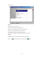
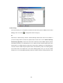
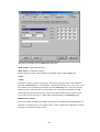
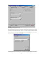
802.11b WLAN Outdoor Bridge WAP-5100 User’s Manual Copyright Copyright 2004 by PLANET Technology Corp. All rights reserved. No part of this publication may be reproduced, transmitted, transcribed, stored in a retrieval system, or translated into any language or computer language, in any form or by any means, electronic, mechanical, magnetic, optical, chemical, manual or otherwise, without the prior written permission of PLANET. PLANET makes no representations or warranties, either expressed or implied, with respect to the contents hereof and specifically disclaims any warranties, merchantability or fitness for any particular purpose. Any software described in this manual is sold or licensed "as is". Should the programs prove defective following their purchase, the buyer (and not this company, its distributor, or its dealer) assumes the entire cost of all necessary servicing, repair, and any incidental or consequential damages resulting from any defect in the software. Further, this company reserves the right to revise this publication and to make changes from time to time in the contents hereof without obligation to notify any person of such revision or changes.. All brand and product names mentioned in this manual are trademarks and/or registered trademarks of their respective holders. Federal Communication Commission Interference Statement This equipment has been tested and found to comply with the limits for a Class B digital device, pursuant to Part 15 of FCC Rules. These limits are designed to provide reasonable protection against harmful interference in a residential installation. This equipment generates, uses, and can radiate radio frequency energy and, if not installed and used in accordance with the instructions, may cause harmful interference to radio communications. However, there is no guarantee that interference will not occur in a particular installation. If this equipment does cause harmful interference to radio or television reception, which can be determined by turning the equipment off and on, the user is encouraged to try to correct the interference by one or more of the following measures: 1. Reorient or relocate the receiving antenna. 2. Increase the separation between the equipment and receiver. 3. Connect the equipment into an outlet on a circuit different from that to which the receiver is connected. 4. Consult the dealer or an experienced radio technician for help. FCC Caution: To assure continued compliance.(example-use only shielded interface cables when connecting to computer or peripheral devices). Any changes or modifications not expressly approved by the party responsible for compliance could void the user’s authority to operate the equipment. This device complies with Part 15 of the FCC Rules. Operation is subject to the Following two conditions: (1) This device may not cause harmful interference, and (2 ) this Device must accept any interference received, including interference that may cause undesired operation. Federal Communication Statement Commission (FCC) Radiation Exposure This equipment complies with FCC radiation exposure set forth for an uncontrolled environment. In order to avoid the possibility of exceeding the FCC radio frequency exposure limits, human proximity to the antenna shall not be less than 20 cm(8 inches) during normal operation. R&TTE Compliance Statement This equipment complies with all the requirements of DIRECTIVE 1999/5/CE OF THE EUROPEAN PARLIAMENT AND THE COUNCIL OF 9 March 1999 on radio equipment and telecommunication terminal Equipment and the mutual recognition of their conformity (R&TTE) The R&TTE Directive repeals and replaces in the directive 98/13/EEC (Telecommunications Terminal Safety This equipment is designed with the utmost care for the safety of those who install and use it. However, special attention must be paid to the dangers of electric shock and static electricity when working with electrical equipment. All guidelines of this and of the computer manufacture must therefore be allowed at all times to ensure the safe use of the equipment. Revision User’s Manual for PLANET 802.11b WLAN Outdoor Bridge Model: WAP-5100 Rev: 1.0 (January, 2004) Part No. EM-WAP5100 TABLE OF CONTENTS CHAPTER 1 INTRODUCTION .................................................................................................. 1 1.1 PACKAGE CONTENTS ......................................................................................................... 1 1.2 SYSTEM REQUIREMENTS .................................................................................................... 1 1.3 FEATURES ......................................................................................................................... 2 1.4 SPECIFICATION .................................................................................................................. 2 1.5 W IRELESS PERFORMANCE ................................................................................................. 3 CHAPTER 2 HARDWARE INSTALLATION ............................................................................. 4 CHAPTER 3 PLANET OUTDOOR WLAN MANAGEMENT SYSTEM..................................... 7 3.1 INTRODUCTION .................................................................................................................. 7 3.2 INSTALLATION .................................................................................................................... 7 3.3 USING PLANET OUTDOOR WMS .................................................................................... 10 3.3.1 Kick Start ................................................................................................................ 10 3.3.2 Hosts View ............................................................................................................. 14 3.3.3 Trap View................................................................................................................ 32 CHAPTER 4 TROUBLESHOOTING....................................................................................... 33 Chapter 1 Introduction WAP-5100 is an IEEE 802.11b Wireless Outdoor Bridge, which links two or more remote sites together. It offers up to 11Mbps transmission rate that is higher than an E1 or T1 line, and also eliminates the installation and maintenance cost of a lease line or cable. The special designed housing allows WAP-5100 to be installed in exposed locations under the rigorous weather conditions including heavy rain, wind, and snow. WAP-5100 integrates multi-level security including WEP 64/128-bit encryption, protocol filtering, and SNMP authentication for accessing the management settings. The intelligent antenna alignment feature allows multiple WAP-5100s to get the accurate alignments and have best performance. The POE (Power Over Ethernet) design reduces power cables installation fee and provides more flexibility when selecting the location of WAP-5100 1.1 Package Contents Make sure that you have the following items: • • • • • • • • WAP-5100 x 1 Power Adapter x 1 DC injector x 1 Mounting kit x 1 25m CAT5 cable with RJ-45 plug and ODU connector x 1 0.3m N-type to N-type cable x 1 Quick Installation Guide x 1 Utility and User's manual CD x 1 Note: If any of the above items are missing, contact your supplier as soon as possible. 1.2 System Requirements Before installation, please check the following requirements with your equipment. • • • An x86-based microcomputer running Microsoft Windows 95, 98, Me, NT 4.0, 2000, or XP Microsoft Internet Explorer 4.01 or later A connection to an Ethernet network Particular versions of Windows have the following additional requirements: 1. On Windows 95, Microsoft DCOM95 must be installed. You can obtain DCOM95 from the following Microsoft Web page: http://www.microsoft.com/com/dcom/dcom95/download.asp DCOM95 can also be found on the Microsoft Visual Basic 5.0 CD-ROM (Enterprise, Professional, or Standard edition), in the directory \Pro\Tools\DCOM95. 2. On Windows 98 (with the exception of Windows 98SE, which already includes this component), Microsoft DCOM98 must be installed. You can use the following link to download it: http://www.microsoft.com/com/dcom/dcom98/download.asp 3. On Windows NT 4.0, Service Pack 4 or later must be installed. -1- 1.3 Features • Wireless LAN IEEE802.11b compliant • Solid housing provides protection against rigorous weather conditions • Multi-level security includes 64/128-bit WEP encryption, protocol filtering, and SNMP access control • One detachable N-type female connectors can connect to external antenna for expanding connection distance • Intelligent antenna alignment feature • High speed data transfer rate up to 11Mbps • Auto fall-back data rate for long-distance communication and noisy environments • Provide powerful Windows-base SNMP utility for installation and management • Support DHCP Client • Power over Ethernet design 1.4 Specification Model WAP-5100 Standard IEEE 802.11b Signal Type DSSS (Direct Sequence Spread Spectrum) Modulation BPSK, QPSK, CCK Port 10Base-TX (RJ-45) * 1 Antenna Connector N-type Female * 1 Output Power 100mW Sensitivity -84dBm Operating Mode AP 64/128-bit WEP encryption Security Password protect Protocol filtering Operating Mode Point to Point, Point to Multipoint Frequency Band 2.4 – 2.484GHz Data Rate Up to 11Mbps (1/2/5.5/11) Dimensions (L x W x H) 165 x 135 x 55mm Weight 1130g Operating temperature: -20 – 70 degree C Environmental Specification Storage temperature: -30 – 80 degree C Relative humanity: 5% – 95% (non-condensing) Power Requirement 12V DC, 2.0A -2- Electromagnetic FCC, CE Compatibility 1.5 Wireless Performance The following information will help you utilizing the wireless performance, and operating coverage of WAP-5100. 1. Site selection To avoid interferences, please locate WAP-5100 away from transformers, microwave ovens, heavy-duty motors, refrigerators, fluorescent lights, and other industrial equipments. 2. Environmental factors The wireless network is easily affected by many environmental factors. Every environment is unique with different obstacles, construction materials, weather, etc. It is hard to determine the exact operating range of WAP-5100 in a specific location without testing. 3. Antenna adjustment Please check the specification of the antenna you want to use, and make sure it can be used on WAP-5100. -3- Chapter 2 Hardware Installation Before you proceed with the installation, it is necessary that you have enough information about the WAP-5100. 1. Locate an optimum location for the WAP-5100. 2. Assemble the antennas to WAP-5100. Try to place them to a position that can best cover your wireless network. The antenna’s position will enhance the receiving sensitivity. 3. Using provided CAT5 waterproof cable; connect the waterproof connector port of the WAP-5100 to the ODU port of DC Injector. 4. Using Category 3 or higher UTP or STP cable, connect the RJ-45 port of DC Injector to a 10Mbps or 10/100Mbps Ethernet hub or switch, and connect the management station to a hub or switch on the same LAN. 5. Connect the output cord of power adapter to the DC Injector’s DC input jack, and plug it into an AC outlet to power up the WAP-5100. 6. Connect the green grounding wire on WAP-5100 to the same grounding system with the AC wall outlet. The grounding system must comply with the National Electrical Code and safety standards that apply in your country. Always check with a qualified electrician if you are in doubt as to whether your outdoor installation is properly grounded. Note: ONLY use the power adapter supplied with the WAP-5100. Otherwise, the product may be damaged. -4- ! OUTDOOR INSTALLATION WARNING IMPORTANT SAFETY PRECAUTIONS: LIVES MAY BE AT RISK! Carefully observe these instructions and any special instructions that are included with the equipment you are installing. CONTACTING POWER LINES CAN BE LETHAL. Make sure no power lines are anywhere where possible contact can be made. Antennas, masts, towers, guy wires or cables may lean or fall and contact these limes. People may be injured or killed if they are touching or holding any part of equipment when it contacts electric lines. Make sure there is NO possibility that equipment or personnel can come in contact directly or indirectly with power lines. Assume all overhead lines are power lines. The horizontal distance from a tower, mast or antenna to the nearest power line should be at least twice the total length of the mast/antenna combination. This will ensure that the mast will not contact power if it falls either during installation or later. TO AVOID FALLING, USE SAFE PROCEDURES WHEN WORKING AT HEIGHTS ABOVE GROUND. l Select equipment locations that will allow safe, simple equipment installation. l Don’t work alone. A friend or co-worker can save your life if an accident happens. l Use approved non-conducting lasers and other safety equipment. Make sure all equipment is in good repair. l If a tower or mast begins falling, don’t attempt to catch it. Stand back and let it fall. l If anything such as a wire or mast does come in contact with a power line, DON’T TOUCH IT OR ATTEMPT TO MOVE IT. Instead, save your life by calling the power company. l Don’t attempt to erect antennas or towers on windy days. MAKE SURE ALL TOWERS AND MASTS ARE SECURELY GROUNDED, AND ELECTRICAL CABLES CONNECTED TO ANTENNAS HAVE LIGHTNING ARRESTORS. This will help prevent fire damage or human injury in case of lightning, static build-up, or short circuit within equipment connected to the antenna. l The base of the antenna mast or tower must be connected directly to the building protective ground or to one or more approved grounding rods, using 1 OAWG ground wire and -5- corrosion-resistant connectors. l Refer to the National Electrical Code for grounding details. IF A PERSON COMES IN CONTACT WITH ELECTRICAL POWER, AND CANNOT MOVE: l DON’T TOUCH THAT PERSON, OR YOU MAY BE ELECTROCUTED. l Use a non-conductive dry board, stick or rope to push or drag them so they no longer are in contact with electrical power. Once they are no longer contacting electrical power, administer CPR if you are certified, and make sure that emergency medical aid has been requested. -6- Chapter 3 PLANET Outdoor WLAN Management System 3.1 Introduction The bundled PLANET Outdoor WMS (WLAN Management System) is a powerful utility for managing WAP-5100. This utility is fully compatible with the industry-standard Simple Network Management Protocol (SNMP). A powerful auto-discovery algorithm is built into WMS. With a simple click on the Auto Discovery icon, all compatible devices within the subnet will be discovered. This discovery feature is based on the following techniques: • • DHCP client and IP recovery: The WAP-5100 has a built-in DHCP client, and will request an IP address from a DHCP server so that SNMP management can be carried out. Should there be a failure of the DHCP server, the WAP-5100 will auto-assign itself an IP address (see next) and then automatically negotiate for a new IP address when the server recovers. Auto-IP: When the WAP-5100 cannot get an IP address from a DHCP server, it will auto-assign itself an IP address of 169.254.x.x and a subnet mask of 255.255.0.0. A Windows-based system configured as a DHCP client will use the same algorithm to assign itself an IP address in the same subnet. When the DHCP server comes back on line, users may need to renew their stations’ IP settings; otherwise, Windows may continue to use the previous IP address instead of executing the auto-IP procedure. 3.2 Installation 1. Insert the bundled CD in the CD-ROM drive to initiate the autorun program. Click on the "PLANET Outdoor WLAN Management System" hyperlink to activate the program. Or you can start the installation as follows. A. Click on Start Menu/ Run. B. Enter “E:\UTILITY\Setup.exe” in the appeared box, where “E” is the letter of your CD-ROM drive. C. Click on “OK” button. 2. A Welcome window will appear as below. Please click “Next” to continue. -7- 3. You can click “Browse” to specify the Destination Folder that you want to install the utility. Or you can keep the default setting and click ”Next” to continue. 4. Click “Next” to continue. -8- 5. The setup will start to copy necessary files to your computer. When the Setup Complete window appears, click “Finish” to complete the software installation. -9- 3.3 Using PLANET Outdoor WMS After successfully installing the utility, you can found the icon on your desktop. To activate WMS, you can double click this icon or click Start > Programs > PLANET > PLANET Outdoor WLAN Management System. The main WMS window will then open. 3.3.1 Kick Start It is recommended to use Kick Start function when initial setting up a WAP-5100. Open Start menu and select Kick Start, or click on the icon from the main WMS window, then the Kick Start window appears as below. - 10 - 3.3.1.1 Find This function helps you to quickly locate all compatible devices (include AP and Bridge). Open the Start menu and select Find, or click on the icon , or press F5. Few seconds later, the MAC addresses of all compatible devices will be listed below. If you select a specific device from the left field, its detailed settings will be shown in the right field. - 11 - 3.3.1.2 Preference You can set the parameters for the Kick Start as desired. Open the Start menu and select Preference, a dialog box will appear as below. After completing desired modifications, click OK to close the dialog box and apply the changes to Kick Start. 3.3.1.3 New If the MAC address of the device is already known, you can use this function to connect it directly. Open the Edit menu and select New, or click on the icon , a dialog box will pop up. Enter the MAC address of the device and click OK to make the connection. 3.3.1.4 Delete If you want to remove a specific device from the list, select its MAC address, open the Edit menu and select Delete, or click on the icon . The device will disappear from the list immediately. 3.3.1.5 Delete All It is the similar function as Delete. Open the Edit menu and select Delete All, or click on the icon , all devices will be removed from the list immediately. 3.3.1.6 Ping Test You can use this function to test the IP connectivity between the administrative PC and a specific device. Select the MAC address of the device you want to test from the list, open the Tools menu and select Ping Test, or click on the icon , the test will be executed right away. A dialog box will pop up to inform you whether the test passes or not. If the test fails, please make sure your administrative PC and the device are in the same IP segment. - 12 - 3.3.1.7 Change IP Settings This function allows you to change the IP address of a specific device. Highlight the MAC address of the device from the list, open the Tools menu and select Change IP Settings, or click on the icon , a dialog box will pop up as below. Please note the modified IP address must be in the same subnet as Local Computer; otherwise the OK button remains unavailable. The default password of WAP-5000 is admin. 3.3.1.8 Change Password This function allows you to change the administrative password of the device. Highlight the MAC address of a device from the list, open the Tools menu and select Change Password, or click on the icon , a dialog box will pop up. Type the Old Password, New Password, and confirm New Password again, then click OK button to close the box and apply the changes to the device. 3.3.1.9 Reboot This function allows you to reboot the device without unplugging its power adapter. Highlight the MAC address of a device from the list, open the Tools menu and select Reboot, or click on the icon , a dialog box will pop up and ask for the administrative password. Type in the correct password, then click OK button to close the box and reboot the device. - 13 - 3.3.1.10 Restore Default This function allows you to restore default settings of the device. Highlight the MAC address of a device from the list, open the Tools menu and select Restore Default, or click on the icon ,a dialog box will pop up and ask for the administrative password. Type in the correct password, then click OK button to close the box and restore default settings. 3.3.2 Hosts View Hosts View is the major part of the WMS. It supports not only individual remote management, but also batch mode operation, including multi-monitor, batch upgrade, batch reset, and batch load default settings. Batch mode operation can efficiently reduce administrative efforts when deploying multiple WAP-5100s. Open Start menu and select Start Hosts View, or click on the icon from the main WMS window, then the Hosts View window appears as below. 3.3.2.1 Auto Discovery This function helps you to quickly locate all compatible devices in the same IP subnet as the administrative PC. Open the Host menu and select Auto Discovery, or click on the icon , or press F5. Few seconds later, all compatible devices will be listed below with their information. 3.3.2.2 Monitor Device This function allows you to view the status, statistics, and other configuration information of WAP-5100. Open the Host menu and select Monitor, or click on the icon - 14 - , a monitoring window will pop up as below. Identity The information shown here is read-only. • Device Name: WMS system default category name • Name: Device name assigned by the user for easier identification • S/W Version: Shows the device software version number • H/W Version: Shows the device hardware version number • Current Channel: Shows the wireless channel currently in use on the device Statistics The Statistics window shows both Ethernet and Wireless traffic statistics. Click the icon to start getting the statistics, and click the icon - 15 - to stop. 3.3.2.3 Config This function allows you to configure the parameters of WAP-5100. Open the Host menu and select Config, or click on the icon , a configuration window will pop up. IP WAP-5100 is a DHCP client by default. It will automatically ask the DHCP server for IP address. If you want to assign static IP to WAP-5100, please clear the check box in front of Obtain IP Settings Automatically (By DHCP). Please note WAP-5100 will directly transfer SNMP response packets (confirmation packets) to an administrative PC if it is within the same network segment (the same subnet mask). If an SNMP response packet from a WAP-5100 is destined for an administrative PC on another LAN, the SNMP response packet needs to be forwarded by routers. The default gateway is the closest router to the WAP-5100. If the correct default gateway is set, you can use a WMS manager (i.e. a PC running WMS) physically located in a different subnet to manage this WAP-5100. - 16 - Filter This is a one-way protocol filtering mechanism that prevents the WAP-5100 from transmitting specified protocols packet from a wired Ethernet LAN into the wireless LAN. If you do not require particular protocols on the wireless part of your network, you can save bandwidth by enabling the protocol filter. From the Filter window, there are six protocols listed may be selected for filtering out: • IP Protocol • IPX Protocol • NetBEUI Protocol • AppleTalk Protocol • Other Protocols • Internet Multicast Frames - 17 - Wireless The Wireless window allows you to configure wireless settings of WAP-5100. - 18 - • Name: Assigns the WAP-5100 a unique name that allows the device to be easily identified on the network. • SSID: Identifies the wireless domain that this WAP-5100 is in. A wireless domain, in the case of outdoor bridges, is ordinarily composed of two or more WAP-5100 that are in communication with each other via radio links. Wireless outdoor bridges that will be in communication with each other must be set to use the same SSID in order to be able to establish a wireless link or links. You can type an existing domain name or create a new one. An SSID is case-sensitive and can contain up to 32 characters. • Transmission Rate: Sets the transmission rate of the WAP-5100. In high-interference environments a lower rate can increase overall transmission speed by reducing resends of lost packets. • Basic Rates: This value determines the basic rates used and reported for this BSS by the WAP-5100. The highest rate specified is the rate that the WAP-5100 will use when transmitting broadcast/multicast and management frames. • Channel Number: You can change the channel used by the WAP-5100 from here. WAP-5100 that will be in communication with each other must be set to use the same channel in order to be able to establish a wireless link or links. • Regulatory Domain: Identifies the Regulatory Domain where the WAP-5100 is used. Each country has defined its available channel numbers and transmission power. Bridge Mode There are two selectable options in Bridge Mode. • Point to Point: This is for connecting two remote sites. Each bridge has to know its peer bridge ’s - 19 - MAC address. For example, if Bridge A is to connect with Bridge B, then Bridge B ’s MAC address must be entered on this page for Bridge A, and Bridge A’s MAC address must be entered here for Bridge B. • Point to Multipoint: This is for connecting more than two remote sites. At least one of the WAP-5100 must be set to Point-to-Multipoint mode in such network topology. Other WAP-5100 can be set to either Point-to-Point or Point-to-Multipoint mode. In this mode, up to six other bridges can be connected. Their MAC addresses must be entered here. For example; if Bridge A is the master bridge and needs to connect with Bridge 1 and Bridge 2, then when setting Bridge A, the MAC addresses of Bridge 1 and Bridge 2 must be entered on the Bridge Mode page. Likewise, Bridge 1 and Bridge 2 must be set to Point to Point mode, and Bridge A ’s MAC address must be entered as the peer bridge MAC address. - 20 - Encryption Click the Encryption tab to set up the security settings of WAP-5100. - 21 - There are two selectable options in Method pull-down menu: • WEP: Disable - Disable data encryption • WEP: Enable - Enable data encryption If data encryption is enabled, there would be two available options in Key Length menu: • 64-bit • 128-bit There are two ways to generate a security key. The first is by entering any text in the Passphrase field. Click the Generate button. For 64-bit WEP, it will generate four keys, Key 1, Key 2, Key 3, and Key 4. Select a key number from the dropdown list of the Default Key box. If you do not manually select a key, key 1 will be selected. For 128-bit WEP, only one key will be generated. Click OK. Another WEP key generation method is to insert the key values directly from the keyboard. Enter your own key into one of the Key 1~4 fields. Select that field number in the Default Key field. SNMP Access Control WAP-5100 contains an SNMP access table to limit access to its configurations. By default there is no restriction on accessing the AP. For security reason, access to WAP-5100 configuration should be restricted to only those who require access. - 22 - When you select SNMP Access Control, the system will display four blank fields for setting (maximum of 4 SNMP devices can be set). Right-click on a blank in the list and click Edit Address. The New/Edit Address dialog box will appear. Type in the IP address and set the password for the SNMP device. There are two levels of access rights can be assigned: • Read: The user can read all information except the Access Control settings, but is not allowed to alter anything. • Read/Write: The user can read and change all settings. Please note do not set all SNMP devices in the table to Read only; otherwise the WAP-5100 is impossible to be modified. The only solution is to reset the device back to factory defaults by using Kick Start. Trap Server When the WAP-5100 is powered on, or an Ethernet port becomes active, an event log will be generated indicating the time, the IP address of the reporting WAP-5100, and the event. You can view and save the event logs from the station as a Trap Server. To assign a trap server, click Trap Server tab. - 23 - Click the icon and assign a station as a trap server by entering its IP address. To remove a trap server from the list, highlight it and click the icon . Click the icon to remove all assigned trap servers from the list. Advanced You may set the packet size of RTS Thresholds and Fragmentation Thresholds in the Advanced window. - 24 - Export/Import Configuration Profile The configuration file can be saved to a text file and safely kept. This configuration file can also be imported to recover the WAP-5100’s setting, if there is an accident. This profile can also be copied to the other WAP-5100. To do this, first click the Export button in the Config window. Then enter the file name for the configuration profile to be saved to. A configuration file can also be imported to recover the WAP-5100’s original settings. This profile can - 25 - also be copied to the other WAP-5100. To do this, first click the Import button in the Config window. Then enter the file name for the configuration profile to be imported from. Click Next. On Step 2 screen, you can select or clear the sessions of the configuration profile to be imported. Click Next. The configuration profile does not contain the security key settings. The attributes of security keys are externally write-only and cannot be saved into the configuration file. If you select Encryption session to be imported, it will display the Encryption window before Step 3 screen and ask you to enter the security key settings manually. - 26 - Confirm the configurations again in Step 3 screen, then click Import button to start the process. 3.3.2.4 Antenna Alignment The WAP-5100 is usually used to connect two or more separate LANs via the radio link with a directional antenna to extend the distance between two wireless bridges. Sometimes the distance between two LANs might be several kilometers. Owing to the nature of the directional antenna, the higher the antenna gain is, the narrower the angle of the wave propagation will be. In order to achieve the best radio performance of WAP-5100, the antenna alignment utility is developed to help the technician in easily installing the antenna as well as achieving the best radio performance. Step 1: Access the Antenna Alignment function Open the Host menu and select Antenna Alignment, or click on the icon Alignment window will pop up. - 27 - , an Antenna Step 2: Set the parameters for testing The calculation of the antenna alignment is conducted by the following procedure: • Bridge A sends a packet to Bridge B • When Bridge B successfully receives the packet from Bridge A, it will automatically echo the packet back. • When Bridge A receives the packet echoed back by Bridge B, it can calculate the throughput and can present it as PPS (packets per second) and KBPS (kilobytes per second). The higher the throughput is, the better alignment is achieved. Since every installation is different (for example, the difference in distance, temperature, humidity, and alignment angle) no standard reference can be given. The user can specify the following parameters for each test: • Packet Length: Ranges from a minimum of 64 bytes to a maximum of 1514 bytes, as Ethernet does. The larger the packet size is, the higher the error rate is likely to be. • Packet Count: The packet number to be sent during the test. The larger the packet count is, the more time the test will take. • Peer Bridge: In a Point to Multi-Point application environment, all the wireless bridges configured to communicate with each other are shown in the pull-down Peer Bridge box. A peer bridge has to be specified by indicating its MAC address before starting the antenna alignment test. The selected bridge must be set up to be able to communicate with the bridge initializing the alignment test. Tips in setting the parameters: - Rough alignment: When the bridges are first set up, the antennas of the bridges are not yet aligned under an optimum condition. It is recommended to use a shorter size and a smaller packet count to perform the test so that test results can be obtained quickly. - Fine Alignment: Once the test reveals that the antenna is just about aligned, enter a longer packet size and larger packet count for the fine alignment. - 28 - Step 3: Execute the test and evaluate the performance After all the parameters have been properly entered, click Start on the right side of the window to execute the test. Test results are immediately presented as a three-dimension graphic. During the antenna alignment test, the bridge might receive interference owing to some unexpected reason. Under this circumstance, the wireless communication data rate will automatically fall back. The numbers of packets sent or received at different data rates can be viewed as shown below . Step 4: Save the test results to a file The tests may be repeated as described in Step 3 until the antenna is aligned at the optimum position. Then store the test configuration and test results in a file for later use. Click the Save Current Alignment Info icon on the toolbar to open the Save As box. A previously saved test data file can also restored back and shown in the window. Use the previously - 29 - stored file as a reference to compare with the latest test results and evaluate the difference between them. In the following figure, the red line represents the latest test results and the green line represents the previous test results. Step 5: View test results as a three-dimensional graphic The Antenna Alignment utility allows the user to view the test results in multiple ways: • 2D (two-dimensional) or 3D (three-dimensional) • Zoom in for a magnified view or zoom out for a wider view • Rotation: rotate the view angle from side view • Elevation: rotate the view angle from top view 3.3.2.5 Restart You can restart a selected WAP-5100 by opening the Host menu and select Restart, or click on the icon . A warning message will pop up for confirmation. Click OK button to restart the device. The restart process will take about 30 seconds. During this period, the WMS program will not be able to query the WAP-5100 via the SNMP protocol. 3.3.2.5 Factory Reset If you want to reset the WAP-5100 to its factory default settings, you can open the Host menu and select Factory reset, or click on the icon . A warning message will pop up for confirmation. Click Yes button to reset factory settings. 3.3.2.6 Upgrade Firmware To upload the latest firmware to the WAP-5100, you can open the Host menu and select Upgrade Firmware, or click on the icon . A dialog box will pop up. You may either enter the file name in - 30 - the Firmware File field or browse the file by clicking the Browse button, then click Upgrade button to start the process. 3.3.2.7 New/Edit/Delete Host Address Click the icon to open the New/Edit Address dialog box. After enter the IP address of a WAP-5100, WMS will automatically find the device and list it on the Host Table. You can also select any WAP-5100 on the table and click the icon to delete it whenever it is no longer necessary. 3.3.2.8 Import/Export Host Table The Host Table is a very powerful function to support a mass deployment of PLANET outdoor WLAN products. You can combine several WAP-5100s together with WAP-5000 to form a group with a specific Host Table name so that you can divide the wireless network into many small groups. • Create Host Table via Automatic Discovery Click Automatic Discovery icon to find all compatible devices. Select the desired devices (for example, located in building A). Choose Export Host Table to save the Host Table to a file (for convenience, you can save the Host table on a network disk for ease of access). • Import Host Table to check device’s availability Import the Host Table from a file (for convenience, you can retrieve the Host table on a network disk for the ease of access). Once the Host Table is imported, WMS will automatically check the availability of APs and other compatible devices listed in the Host Table. This is an extremely powerful feature to make up for the inadequacy of Auto-Discovery. Auto-Discovery can only find compatible devices when they are alive. Failed devices cannot be found via Auto-Discovery. The devices listed in the Host Table should be available and provide the service. If they do not exist, WMS can report their absence immediately so that the system administrator can take immediate action. - 31 - 3.3.3 Trap View If the administrative PC has been assigned as a Trap Server of a WAP-5100, you can use Trap View to view the trap log information of the WAP-5100. Open Start menu and select Start Trap View, or click on the icon from the main WMS window, then the Trap View window appears as below. The log shows the time, the IP address of the reporting WAP-5100, and the event. You can save, open, and delete log files through the File menu. - 32 - Chapter 4 Troubleshooting This chapter provides solutions to problems usually encountered during the installation and operation of the WAP-5100. How do I set the WAP-5100 back to its factory default settings? You can apply Factory Reset option from the menu of the WLAN Management System (WMS) or use Kick Start function by the following way: w Connect the WAP-5100 to your PC. Please make sure the Ethernet connection is normal. w Open WLAN Management System (WMS) application and click Kick Start icon. w Click Find icon from WLAN Kick Start window or press <F5> key to search the WAP-5100. Right-click the WAP-5100 that you want to reset and select Restore Default option. The WMS utility cannot detect a WAP-5100 on the same network. w Make sure the WAP-5100 is powered on and connected to an Ethernet network. w Check the IP addresses assigned to the WAP-5100 and WMS terminal PC. They should be in the same subnet and unique. For example, if the WAP-5100’s IP address is 192.168.1.5 with a mask of 255.255.255.0, then the PC’s IP address should be 192.168.1.x with a mask of 255.255.255.0. Do the antennas need line of sight to operate? The antennas connecting to a WAP-5100 need not only visual line of sight, but also radio line of sight. Radio line of sight includes an elliptical region around the visual line of sight called the Fresnel zone. For optimal performance, make sure the Fresnel zone is clear of all obstructions including trees, power lines, buildings, and geographic obstacles. The throughput rate is slow. Check the following: w Verify the antenna, connector, and cabling are well connected. w Change the direction of the antenna slightly. w There may be interference, possibly caused by a microwave oven, 2.4-GHz wireless phone, or metal objects. Move these interference sources or change the location of the wireless PC or AP. w Change the wireless channel on the WAP-5100. w Verify the network traffic does not exceed 37% of bandwidth. w Lower the broadcast rate of wired network to no more than 10 broadcast messages per second w Verify wired network topology and configuration. If Technical Support assistance is required, please prepare the following information ready before you contact us. w LED status w A list of the product hardware (including revision levels), and a brief description of the network structure w Details of recent configuration changes, if applicable If it appears that more in-depth support is required, have the following information on hand before seeking assistance: w What you were doing when the error occurred w What error messages you saw w Whether the problem can be reproduced w The serial number of the product w The firmware version and the debug information - 34 -