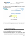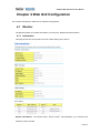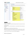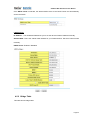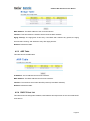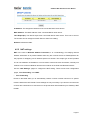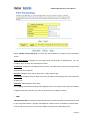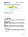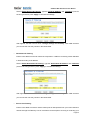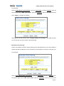
1
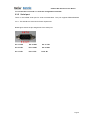
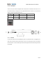
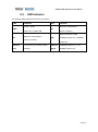
JetWave IWC 5630 Series Industrial-grade WLAN controller User Manual V1.0 Sep.15, 2015 JetWave IWC 5630 Series User Manual Copyright Copyright © 2014 all rights reserved. No part of this publication may be reproduced, adapted, stored in a retrieval system, translated into any language, or transmitted in any form or by any means without the written permission of the supplier. About This Manual This user manual is intended to guide professional installer to install the JetWave IWC 5630 and how to build the infrastructure centered on it. It includes procedures to assist you in avoiding unforeseen problems. Conventions For your attention on important parts, special characters and patterns are used in this manual: Note: This indicates an important note that you must pay attention to. The Blue Wording is important note that you must pay attention to. The Blue Wording with Big Case is very important note you must pay more attention to. Warning: This indicates a warning or caution that you have to abide. The Red wording is very important you must avoid. Bold: Indicates the function, important words, and so on. JetWave IWC 5630 Series User Manual Federal Communication Commission Interference Statement This equipment has been tested and found to comply with the limits for a Class B digital device, pursuant to Part 15 of the FCC Rules. These limits are designed to provide reasonable protection against harmful interference in a residential installation. This equipment generates uses and can radiate radio frequency energy and, if not installed and used in accordance with the instructions, may cause harmful interference to radio communications. However, there is no guarantee that interference will not occur in a particular installation. If this equipment does cause harmful interference to radio or television reception, which can be determined by turning the equipment off and on, the user is encouraged to try to correct the interference by one of the following measures: - Reorient or relocate the receiving antenna. - Increase the separation between the equipment and receiver. - Connect the equipment into an outlet on a circuit different from that to which the receiver is connected. - Consult the dealer or an experienced radio/TV technician for help. This device complies with Part 15 of the FCC Rules. Operation is subject to the following two conditions: (1) This device may not cause harmful interference, and (2) this device must accept any interference received, including interference that may cause undesired operation. FCC Caution: Any changes or modifications not expressly approved by the party responsible for compliance could void the user's authority to operate this equipment. JetWave IWC 5630 Series User Manual FCC Radiation Exposure Statement: This equipment complies with FCC radiation exposure limits set forth for an uncontrolled environment. To avoid the possibility of exceeding radio frequency exposure limits, you shall beep a distance of at least 100cm between you and the antenna of the installed equipment. This transmitter must not be co-located or operating in conjunction with any other antenna or transmitter. The availability of some specific channels and/or operational frequency bands are country dependent and are firmware programmed at the factory to match the intended destination. The firmware setting is not accessible by the end user. JetWave IWC 5630 Series User Manual Content Chapter 1 Introduction ......................................................................................................................... 2 1.1 Introduction .............................................................................................................................. 2 1.2 JetWave IWC 5630 Series Appearance .................................................................................. 3 1.3 JetWave IWC 5630 Major Features......................................................................................... 3 1.4 Supported AP models .............................................................................................................. 4 1.5 Product Package ..................................................................................................................... 4 Chapter 2 Hardware Installation ......................................................................................................... 6 2.1 Professional Installation Required ........................................................................................... 6 Safety Precautions .......................................................................................................................... 6 2.2 Power Installation .................................................................................................................... 6 2.2.1 2.3 DC Input ........................................................................................................................... 6 Power Installation .................................................................................................................... 7 2.3.1 Wiring your Ethernet Port ................................................................................................. 7 2.3.2 SFP socket ....................................................................................................................... 7 2.3.3 USB port ........................................................................................................................... 7 2.3.4 Reset ................................................................................................................................ 7 2.3.5 Serial port ......................................................................................................................... 8 2.3.6 Serial port ......................................................................................................................... 9 2.3.7 Ground .............................................................................................................................. 9 2.4 LED Indicator ......................................................................................................................... 10 Chapter 3 Prepare for Management ................................................................................................. 12 3.1 Basic Factory Default Settings .............................................................................................. 12 3.2 System Requirements ........................................................................................................... 12 3.3 How to Login the Web-based Interface ................................................................................. 13 3.4 Fail to login the Web GUI....................................................................................................... 13 Chapter 4 Web GUI Configuration .................................................................................................... 16 4.1 Monitor ................................................................................................................................... 16 JetWave IWC 5630 Series User Manual 4.1.1 Information...................................................................................................................... 16 4.1.2 Access Points ................................................................................................................. 17 4.1.3 Statistics ......................................................................................................................... 17 4.1.4 Event/Alarm .................................................................................................................... 18 4.2 System ................................................................................................................................... 19 4.2.1 Basic Settings ................................................................................................................. 19 4.2.2 Time Settings .................................................................................................................. 20 4.3 Access Points ........................................................................................................................ 21 4.3.1 AP Settings ..................................................................................................................... 21 4.3.1.1 AP model settings --WIFI ............................................................................................ 22 4.3.1.2 AP model settings --Cellular ....................................................................................... 27 4.3.1.3 Per-AP settings ........................................................................................................... 28 4.4 WLANs ................................................................................................................................... 29 4.4.1 4.5 WLAN profile .................................................................................................................. 30 Network Settings .................................................................................................................... 33 4.5.1 IP Settings ...................................................................................................................... 33 4.5.2 Bridge Table .................................................................................................................... 35 4.5.3 ARP Table ....................................................................................................................... 36 4.5.4 DHCP Client List ............................................................................................................. 36 4.5.5 NAT settings ................................................................................................................... 37 4.6 Security .................................................................................................................................. 39 4.6.1 Firewall settings .............................................................................................................. 39 4.6.2 MAC ACL ........................................................................................................................ 42 4.7 AAA ........................................................................................................................................ 42 4.7.1 Radius settings ............................................................................................................... 42 4.7.2 Radius server ................................................................................................................. 43 4.8 Management .......................................................................................................................... 44 4.8.1 Remote Setting ............................................................................................................... 44 4.8.2 SMTP Configuration ....................................................................................................... 46 4.8.3 Password Settings .......................................................................................................... 47 JetWave IWC 5630 Series User Manual 4.8.4 Firmware Upgrade .......................................................................................................... 47 4.8.5 Configuration File ........................................................................................................... 48 4.8.6 Certificate File................................................................................................................. 49 4.9 Tools ...................................................................................................................................... 50 4.9.1 System Log..................................................................................................................... 50 4.9.2 Ping ................................................................................................................................ 51 4.10 Main Entry .......................................................................................................................... 52 4.10.1 Save ............................................................................................................................... 52 4.10.2 Logout ............................................................................................................................. 52 4.10.3 Reboot ............................................................................................................................ 52 Chapter 6 Troubleshooting ............................................................................................................... 55 5.1 General Question................................................................................................................... 55 5.1.1 How to know the MAC address of the WLAN controller?............................................... 55 5.1.2 What if I would like to reset the unit to default settings? ................................................ 55 5.1.3 What if I cannot access the Web-based management interface? .................................. 55 Revision History ................................................................................................................................. 56 JetWave IWC 5630 Series User Manual Chapter 1 Introduction Page 1 JetWave IWC 5630 Series User Manual Chapter 1 Introduction 1.1 Introduction The user manual is applied to Korenix JetWave IWC 5630 Series Industrial-grade WLAN controller. For detail product specification, please download the latest datasheet from Korenix web site. Page 2 JetWave IWC 5630 Series User Manual 1.2 JetWave IWC 5630 Series Appearance Figure - JetWave IWC 5630 Appearance 1.3 JetWave IWC 5630 Major Features • Central-managed wireless network: Integrated AP auto discovery and auto provision for fast installation and deployment • Enhanced wireless security: Minimal deployment for built-in secure gateway and built-in RADIUS server • Advanced wireless mobility: Less than 100ms server-based fast roaming • WPA2-personal/enterprise and IEEE 802.11i-compliant wireless security • IEEE 802.1x/RADIUS supported • Up to 25 managed APs and 1000 concurrent users • Up to 8 WLAN radio profiles supported & 8 VAPs per profile • IP30 grade sheet metal chassis • -40~75℃ operating temp • DC 9~36V power input with polarity auto reverse protection • EN50022 DIN-rail mount Page 3 JetWave IWC 5630 Series User Manual 1.4 Supported AP models Supported AP models are JetWave 3200 series include all JetWave 3200/3300/3400 product series with dedicated firmware. Please make sure you are using controller-based AP firmware. 1.5 Product Package The product package you have received should contain the following items. If any of them are not included or damaged, please contact your local vendor for support. Package: JetWave IWC5630 Unit Din-Rail Mounting Kit 2-pin Power connector Quick Installation Guide Console cable (3pin/DB9) Note: Please download the Utility, User Manual from Korenix Web Site. Note 1: Check the Korenix web site order information for new accessories, new version user manual, MIB file, firmware and Utility. Note 2: Different model needs different number of the accessories. If you are not familiar with the feature of the accessories, please consult with our Sales or Technical Service Engineer. Page 4 JetWave IWC 5630 Series User Manual Chapter 2 Hardware Installation Page 5 JetWave IWC 5630 Series User Manual Chapter 2 Hardware Installation This chapter describes safety precautions and product information before installing JetWave IWC 5630 Series. 2.1 Professional Installation Required 1. Please seek assistance from a professional installer for field installation or professional IT Engineer for indoor installation. 2. The JetWave IWC 5630 series is distributed through distributors and system installers with professional technicians and will not be sold directly through retail stores. Safety Precautions 1. To keep you safe and install the hardware properly, please read and follow these safety precautions. If you are installing JetWave IWC 5630 series in the field box, for your safety as well as others’, 2. please seek assistance from a professional installer who has received safety training on the hazards involved. Keep safety as well as performance in mind when selecting your installation site, especially where there are electric power and phone lines. Please note the following things as well: 3. Do not use a metal ladder; Do not work on a wet or windy day; Wear shoes with rubber soles and heels, rubber gloves, long sleeved shirt or jacket. If you are installing JetWave IWC 5630 series in the indoor office or factory, be aware of the power source and grounding must be well installed. 4. Note that Field EMD (Lightning) DAMAGE IS NOT COVERED UNDER WARRANTY. 2.2 Power Installation The system provides DC power input. 2.2.1 DC Input 1. There is one 2-pin terminal block within the package for screwing the DC wires. It is a good practice to turn off the system power, and to unplug power terminal block before making wire Page 6 JetWave IWC 5630 Series User Manual connections. 2. Insert the positive and negative wires into the V+ and V- contact on the terminal block connector. Tighten the wire-clamp screws to prevent DC wires from being loosened. The range of the suitable electric wire is from 12 to 24 AWG. 3. The typical and suggest power source is DC 24V, the acceptable range is range from 9~36V. Please note that while you connect 36VDC, make sure the inrush voltage shall be under 10% (39.6V). 2.3 Power Installation 2.3.1 Wiring your Ethernet Port There are four Gigabit Ethernet ports. The 4 ports are standard RJ-45 form factor. They can support 10Base-TX, 100Base-TX and 1000Base-T. The 10/100Base-TX also supports both full and half duplex mode. All the Ethernet ports will auto-detect the signal from connected devices to negotiate the link speed and duplex mode. Auto MDI/MDIX allows users to connect another switch, hub or workstation without changing straight through or crossover cables. In some cases, the MDI/MDI-X may requests the connected device support auto-negotiation. Available Cable Type: 10Base‐T: 2‐pair UTP/STP Cat. 3, 4, 5 cable (100m) 100 Base‐TX: 2/4‐pair UTP/STP Cat. 5 cable (100m) 1000 Base‐T: 4‐pair UTP/STP Cat. 5 cable (100m) 2.3.2 SFP socket SFP socket is 100/1000 fiber SFP socket combo, combo with 10/100/1000Base-T. It can be used as a WAN port. 2.3.3 USB port The port supports USB flash device. This interface is reserved for future requirement. 2.3.4 Reset There is one Reset button located at the bottom of the device. This is design for user to reboot the system port or force reset the configuration to default. The function is depended on how much time you press the button. Press 3 seconds to reboot the device. Page 7 JetWave IWC 5630 Series User Manual Press more than 7 seconds can reset the configuration to default. 2.3.5 Serial port There is one RS232 serial port for serial communication. The port supports RS232/422/485 3-in-1. This interface is reserved for future requirement. Below figure shows the pin assignment of the serial port. Pin 1: DCD Pin 2: RXD Pin 3: TXD Pin 4: DTR Pin 5: GND Pin 6: DSR Pin 7: RTS Pin 8: CTS Pin 9: RI Page 8 JetWave IWC 5630 Series User Manual 2.3.6 Serial port There is one 3-pin console for diagnostic and command line on the bottom of the device. The 3 pin indicates below pin assignment of the typical RS-232 serial connection. You can wire the cable by yourself or purchase from Korenix. Pin 1 Pin 2 Pin 3 Diag. Socket GND(Ground) Receive Data (RD) Transmit Date (TD) D-Sub 9 GND(Ground) Transmit Date (TD) Receive Data (RD) 2.3.7 Ground To ensure the system will not be damaged by noise or any electrical shock, we suggest you to make exact connection with the Earth Ground. There is one earth ground screw on the bottom side of the device. Loosen the earth ground screw then tighten the screw after earth ground wire is connected. Page 9 JetWave IWC 5630 Series User Manual 2.4 LED Indicator The following table indicates the LED of your device. LED Indication Power LED Status PWR Indication Status for Customization S1 Green ON = System ON (Green or Amber) Status of the SFP socket Status for Customization S2 SFP 1000Mbps (Green on) / 100Mbps (Green or Amber) (Amber on) Ethernet Link (Green on) / Activity (Green Ethernet 1000Mbps (Amber on) / 10 or Port blinking) Speed 100Mbps (Amber off) Page 10 JetWave IWC 5630 Series User Manual Chapter 3 Prepare for Management Page 11 JetWave IWC 5630 Series User Manual Chapter 3 Prepare for Management Using Web GUI Configuration to setup JetWave IWC 5630 Series. This chapter describes the preparation for management. In your first time access the device, you can refer to the Basic Factory Default Settings to know the default settings and the default IP of the device. 3.1 Basic Factory Default Settings We’ll elaborate the JetWave IWC 5630 Series basic factory default settings. You can re-acquire these parameters by default. This info is easier for you to find the device and access the WLAN controller’s configuration interface. For further info, please refer to configuration guide of the feature set. Table 1 JetWave IWC 5630 Basic Factory Default Settings Features Factory Default Settings Username admin Password admin Model Name IWC 5630 Device Name korenixXXXXXX (X represents the last 6 digits of Ethernet MAC address) Default IP IP Address 192.168.10.1 Subnet Mask 255.255.255.0 Gateway 0.0.0.0 Console Type 3-pin (Tx, Rx, GND), 115200, N/8/1 3.2 System Requirements Before configuration, please make sure your system meets the following requirements: A computer coupled with 10/100/1000 Base-T(X) adapter; Configure the computer with a static IP address of 192.168.10.x (X cannot be 0, 1, nor 255), as the default IP address of JetWave IWC 5630 Series is 192.168.10.1 (Eth 1/2/3 of IWC 5630). A Web browser on PC for configuration such as Microsoft Internet Explorer 6.0 or above, Google Chrome or Firefox is preferred. Note: If you want to do throughput test, not just configure the switch, please notice that the throughput of the high performance and low performance CPU must be different. Page 12 JetWave IWC 5630 Series User Manual 3.3 How to Login the Web-based Interface The system provides you with user-friendly Web-based management tool. Open Web browser and enter the IP address (Default: 192.168.10.1) into the address field. You will see the WELCOME page as below. Figure – Web GUI Login Page Enter the name of Account (Default: admin) and password (Default: admin) respectively and click “Login” to login the main page of the device. As you can see, this management interface provides main options in the above, which are Monitor, System, Access points, WLANs, Network Settings, Security, AAA, Management, Tools, Save, Logout and Reboot. Remember to save to flash after configuration applied to keep consistency between system reboot. Note: The username and password are case-sensitive! 3.4 Fail to login the Web GUI If you failed to login the web GUI, there are something you can do for troubleshooting. 1. Korenix web management page is developed by JAVA. It allows you to use a standard web-browser such as Microsoft Internet Explorer, or Mozila, to configure and interrogate the switch from anywhere on the network. The IE 5.0 or later versions do not allow Java applets to open Page 13 JetWave IWC 5630 Series User Manual sockets by default. Users have to directly modify the browser settings to selectively enable Java applets to use network ports. 2. Please disable the firewall setting of your browser. The firewall setting may block the connection from your PC to the device. The firewall may stop the firmware upgrade, configuration backup and restore as well. Note that after finished the setting, re-enable your firewall to protect your PC. 3. Check the IP Setting, your PC and managed device must be located within the same subnet. 4. The Web UI connection session of the device will be logged out automatically if you don’t give any input after 30 seconds. After logged out, you should re-login and key in correct user name and password again. 5. The new JAVA version may have different security policy in different versions, please contact Korenix engineer ([email protected]) once you have problem for login. Page 14 JetWave IWC 5630 Series User Manual Chapter 4 Web GUI Configuration Page 15 JetWave IWC 5630 Series User Manual Chapter 4 Web GUI Configuration This chapter describes the Web GUI for Software Configuration. 4.1 Monitor The Monitor feature set includes Information, Access point, Statistics and Event/alarm. 4.1.1 Information This page shows the current status and some basic setting of the device. System Information: The Model Name, Device Name, Country/Region you selected and Firmware version number. Page 16 JetWave IWC 5630 Series User Manual WAN Setting: It shows the Access type, IP Address, Subnet Mask, Default Gateway, DNS 1/2 and MAC Address of the WAN interface. LAN Setting: It shows the IP Address, Subnet Mask and MAC Address of the LAN interface. Port Status: This table shows the Interface Name, MAC Address, Status and Rate. 4.1.2 Access Points This table shows instant APs list that are discovered by IWC 5630. The status field can be pending, connecting and connected. Pending implies the AP are discovered but not approved. Connecting applies the AP is during the process of approval. When status is connected, it implies the AP is managed by IWC 5630. In action field, you can decide to approve specific AP to be managed by IWC 5630. Poll Interval: The poll interval time setting, range from 0~65534 seconds. If you want to change the poll interval time, press “Stop” and then enter new value, press “Set Interval” to activate new setting. Set Interval: Set new Interval time after enter new poll interval time. Stop: Stop polling the associated clients. 4.1.3 Statistics This page shows the packet counters for transmission and reception regarding to LAN port and WAN port. Page 17 JetWave IWC 5630 Series User Manual Poll Interval: The poll interval time setting, range from 0~65534 seconds. If you want to change the poll interval time, press “Stop” and then enter new value, press “Set Interval” to activate. Set Interval: Set new Interval time after enter new poll interval time. Stop: Stop polling the associated clients. 4.1.4 Event/Alarm This table shows system events. You can observe system activities here, for example, AP joined, AP disconnected or AP deleted, etc. Page 18 JetWave IWC 5630 Series User Manual 4.2 System For users who use the JetWave IWC 5630 series for the first time, it is recommended that you begin configuration from the “System” page shown below: In System pages, there are some configuration pages for the system settings. These setups are introduced in below pages. 4.2.1 Basic Settings Use this page to configure the basic parameters of the device. Device Name: User could give a name for identifying a particular access point here. It allows maximum 15 characters and no spaces. Lan port: 1/2/3 Data Rate: Configure the Speed/Duplex of the port Eth 1. The default value, Auto means Auto-Negotiation. Force speed/duplex is available to setup here. Page 19 JetWave IWC 5630 Series User Manual Wan port: Data Rate: the setting is the same as Lan port Data rate. Country/Region: Select the country you are installed. The channel number may be different based on your country. 802.1Q VLAN: Enable or Disable 802.1Q VLAN. With 802.1Q enabled, the packet will attach the 1Q VLAN tag inside. To assign the VLAN ID for each AP profile, you should enable 802.1Q VLAN first. Here is the global VLAN Enable setup. Management VLAN ID: This is the management VLAN ID of the device. Only the client within the same management VLAN can access the device’s management interface. To enable Management VLAN ID, you must enable “802.1Q VLAN” and assign “VLAN ID” for each AP profile first. 4.2.2 Time Settings Use this page to configure the Time Settings. You can configure current time, time zone and configure NTP protocol to synchronize system time with a public time server over the internet. Page 20 JetWave IWC 5630 Series User Manual Current Time: You can manually type the current time or get the time from you PC. Click “Get PC time”, the current time will be updated according to your PC’s time. Time Zone Select: Select the time zone of your country from the dropdown list. NTP: You can select “Enable NTP client update” in this page, then the NTP feature will be activated and synchronize from the remote time server. NTP Server: Select the time server from the “NTP Server” dropdown list or manually input the IP address of available time server into “Manual IP”. Press “Apply” to activate the settings. 4.3 Access Points In Access Points category, you can set pre-configured AP model setting and per-AP settings for APs that are managed by IWC 5630. Pre-configured AP model settings are categorized by AP model. For example, JetWave 3220 has dual radios. You can configure +radio settings for each radio and all JetWave 3220 share the same AP model settings by default. For specific AP configuration, per-AP setting is also supported for dynamic RF environment. For example, AP model setting set to channel 6 and per-AP model setting set to channel 11. Once per-AP settings applied, it will override model radio settings. To clear an AP from IWC 5630 system, you can “delete AP” and AP-related information will be removed. In such circumstance, the AP will be viewed as a brand-new AP in AP discovery stage. 4.3.1 AP Settings Use this page to configure the parameters for wireless LAN access points. Page 21 JetWave IWC 5630 Series User Manual Model list: Supported JetWave AP models will be listed in the list. Select the model you want to configure and the related settings will be display below. Radio selection will be on the right of Model list. 4.3.1.1 AP model settings --WIFI Use this page to configure WIFI radio of JetWave devices. The following picture uses JetWave 3220 as example. Auto-Approval: Check the button to automatically approve join requests from the APs if you do not want to manually approve each AP of them. Disable Wireless LAN Interface: Check this option to disable WLAN interface, then the wireless module of the AP will stop working and no wireless device can connect to it. Model name: The field shows the model name of the AP, not editable. Page 22 JetWave IWC 5630 Series User Manual 802.11 Mode: The AP/Gateway can communicate with wireless devices of 802.11n/a/g. You can also select 802.11A only, 802.11G only, 801.11A/N and 802.11 G/N and make it work under an appropriate wireless mode automatically. Frequency/Channel: Channel varies much as the available band differs from country to country. Select a proper operating channel in the drop-down list according to your situation. The 802.11G and 802.11G/N are 2.4G band which supports 12~13 channels. The 802.11A and 802.11A/N are 5.8G band, this product support Band 1 (36, 40, 44, 48) and Band 4 (149, 153, 157, 161, 167) Extension Channel : The attribute will be only displayed when using 802.11 A/N mode. Channel Mode: Two levels are available: 20MHz and 20/40MHz. The latter one can enhance the data rate more effectively, but takes more bandwidth, thus cause potential interference. The attribute will be only displayed when using 802.11 A/N mode. WLAN Profile: Select the WLAN profile for this radio. Please refer to section 4.4 WLAN category for the configuration of WLAN profile. Check “Show Advanced Setting” to proceed advance settings. These settings are only for more technically advanced users who have a sufficient knowledge about wireless LAN. Some of these settings should not be changed unless you know what effect the changes will take. And some of the modification on them may negatively impact the performance of your wireless network. Page 23 JetWave IWC 5630 Series User Manual HT Protect: Enable HT (High Throughput) protect to ensure HT transmission with MAC mechanism. Under 802.11n mode, wireless client can be divided into HT STA and Non-HT STA, among which the one with HT protect enabled gets higher throughput. Maximum Output Power: Specify the signal transmission power. The higher the output power is, the wider the signal can cover, but the power consumption will be greater accordingly. Usually “Full” with proper antenna is preferred. Half: 1/2 of Full (Full -3dBm), Quarter: 1/4 of Full (Full -6dBm), Eighth: 1/8 of Full (Full – 9dBm). Date Rate: Usually “Auto” is preferred. Under this rate, the AP/Gateway will automatically select the highest available rate to transmit. In some cases, however, like where there is no Page 24 JetWave IWC 5630 Series User Manual great demand for speed, you can have a relatively-low transmit rate for compromise of a long distance. Extension Channel Protection: This is to avoid conflict with other wireless network and boost the ability of your device to catch all 802.11g transmissions. However, it may decrease wireless network performance. Compared to CTS-Self; the transmission amount of CTS-RTS is much lower. WMM Support: WMM (Wi-Fi Multimedia) is a subset of 802.11e. It allows wireless communication to define a priority limit on the basis of data type, thus those time-sensitive data, like video/audio data, may own a higher priority than common one. A-MPDU/A-MSDU Aggregation: Under AP mode, the data rate of your AP could be enhanced greatly with this option enabled; however, if your wireless clients don’t support A-MPDU/A-MSDU aggregation, it is recommended not to enable it. Short GI: Under 802.11n mode, enable it (Short Guard Interval) to obtain better data rate if there is no negative compatibility issue. RTS Threshold: The AP/Gateway sends RTS (Request to Send) frames to certain receiving station and negotiates the sending of a data frame. After receiving an RTS, that STA responds with a CTS (Clear to Send) frame to acknowledge the right to start transmission. The setting Page 25 JetWave IWC 5630 Series User Manual range is 0 to 2347 in byte. Fragmentation Threshold: Specify the maximum size in byte for a packet before data is fragmented into multiple packets. Setting it too low may result in poor network performance. Leave it at its default of 2346 is recommended. Beacon Interval: Specify the frequency interval to broadcast packets. Enter a value between 20 and 1024. The default value is 100ms. DTIM Interval: DTIM, which stands for Delivery Traffic Indication Message, is contained in the data packets. It is for enhancing the wireless transmission efficiency. The default is set to 1. Enter a value between 1 and 255. Preamble Type: It defines some details on the 802.11 physical layer. “Long” and “Short” are available. IGMP Snooping: IGMP snooping is the process of listening to IGMP network traffic. By enabling IGMP snooping, the AP will listen to IGMP membership reports, queries and leave messages to identify the ports that are members of multicast groups. Multicast traffic will only be forwarded to ports identified as members of the specific multicast group or groups. RIFS: RIFS (Reduced Interframe Spacing) is a means of reducing overhead and thereby increasing network efficiency. Link Integration: This is also known as Link Fault Pass-Through. This feature allows you to bind the Ethernet port 1 (Eth1) and Wireless LAN interface together. Once one of them fails, the other interface becomes down as well. Disable: Disable the Link Integration. WLAN links LAN: Single direction only while the WLAN failure, the binding Ethernet port will become link down. LAN links WLAN: Single direction only while the LAN Ethernet port failure, the binding WLAN radio will be shut down. WLAN and LAN link each other: This is Bi-directional integration no matter while LAN Ethernet port failure or WLAN radio failure. Page 26 JetWave IWC 5630 Series User Manual Space in Meter: To decrease the chances of data retransmission at long distance, the AP/Gateway can automatically adjust proper ACK timeout value by specifying distance of the two nodes. This is very important especially for long distance transmission. Correct Space in Meter helps to get better response time and performance. Press “Apply” to activate the new setting. 4.3.1.2 AP model settings --Cellular Use this page to configure cellular radio of JetWave devices. The following picture uses JetWave 3320 as example. Auto-Approval: Check the button to automatically approve join requests from the APs if you do not want to manually approve each AP of them. Disable 3G/Cellular Interface: You can disable the 3G/LTE interface manually. APN: Every ISP has a specific APN (Access Point Name) assigned to its cellular network. The system can read this name from the SIM card. You can also find this setting by contacting your ISP to know this. Once you failed to connect your 3G/LTE cellular network, this is the first way you can check. Please check with your ISP to know the APN and correctly input the setting through the page. Page 27 JetWave IWC 5630 Series User Manual User Name: The user name for the 3G/LTE connection. Normally, this is provided by your ISP. Password: The password for the 3G/LTE connection. Normally, this is provided by your ISP. Authentication Type: You can select CHAP or PAP per your ISP request. Normally, this is provided by your ISP. Reconnection Delay: Reconnection Delay time is the delay time for each 3G/LTE Retry. Reconnection Retries: This is the times of Reconnection Retry. While 3G/LTE is not connected, the system will retry the connection according to the Reconnection Delay time and Retry times. WAN Redundancy: The product can support WAN redundancy feature. In default, the setting is Fixed 3G/Cellular, that means you can use 3G/LTE and Ethernet WAN port at the same time. You can change the settings to WAN First. WAN first means the 3G/LTE feature is only activated when the Ethernet WAN port link down or failure. Auto IP Report: Most of the ISP assigns the dynamic IP address to the 3G/LTE clients and change the IP address every period of time. While you need to remotely control the gateway, you may need additional information generated from the remote 3G/LTE client device. The Auto IP Report in JetWave 3320/3420 can meet your need while you need to know the IP address from the product. Enable Auto IP Report: Press Enable Auto IP Report, the system will automatically update the system information to remote server/URL. IP Report to URL: Type the correct URL here for your Gateway report to. You can build your own server, rent URL address from ISP or Google Cloud service also supports this functionality. Please check with your ISP or create through Google cloud. Press “Apply” to activate the new setting. 4.3.1.3 Per-AP settings Currently managed AP will be listed in per-AP setting. Click Edit to enter Per-AP setting configuration page. The description of the AP will be displayed when mouse pointer over Edit button. This is helpful to make sure you are configuring the AP you want. You can click the MAC Page 28 JetWave IWC 5630 Series User Manual address to retrieve the current settings of the AP. Please refer to 4.3.1.1 and 4.3.1.2 for the settings of WIFI and cellular settings for specific AP settings. 4.4 WLANs In WLAN category, you can configure WLAN profiles for AP radios. Up to 8 WLAN profiles are supported. There will be a default WLAN profile that functions as the default settings of WIFI radio. Default WLAN profile can’t be deleted but editable. Click Add button to create a new WLAN profile and click Edit/Del to edit/delete an existing WLAN profile. Page 29 JetWave IWC 5630 Series User Manual 4.4.1 WLAN profile In WLAN profile settings configuration page, you can configure the profile name and description. You can have an outlook of all VAP settings in the page and up to 8 VAP profiles can be configured. Click Enable checkbox to enable a configured VAP in the WLAN profile. Click Edit to edit the settings of the VAP. VAP configuration page Click Edit in WLAN profile settings page to enter VAP configuration page. There will be 2 categories: basic settings and security settings. Page 30 JetWave IWC 5630 Series User Manual In basic settings: VAP description: Enter the description of the VAP. Wireless Network Name (SSID): This wireless network name is shared among all associated devices in your wireless network. Keep it identical on all those devices. Note that the SSID is case-sensitive and cannot exceed 32 characters. Broadcast SSID: Under AP mode, hiding network name is necessary when you are in a wireless environment that may have potential risk. By disabling broadcast SSID, the clients cannot scan and find the AP/Gateway, so that malicious attack by some illegal clients could be avoided. Wireless Separation: Wireless separation is an ideal way to enhance the security of network transmission. Under the AP mode, enable “Wireless Separation” can prevent the communication among associated wireless clients. WMM Support: WMM (Wi-Fi Multimedia) is a subset of 802.11e. It allows wireless communication to define a priority limit on the basis of data type, thus those time-sensitive data, like video/audio data, may own a higher priority than common one. Page 31 JetWave IWC 5630 Series User Manual Max. Station Num: In Wireless AP mode, you can define the maximum amount of wireless clients allowed to be connected. The maximum client of the system is 64. The most user access at the same time may cause system busy and the performance becomes lower. It is suggested to assign the value depends on how much bandwidth your client generally need, and totally bandwidth suggest is under 250Mbps for TCP based data transmission. In security settings: Network Authentication Open System: It allows any device to join the network without performing any security check. Shared Key: Data encryption and key are required for wireless authentication. WPA with RADIUS: With warrant (username, password and etc.) offered by user, this kind of authentication can be realized with specific RADIUS server. This is the common way to be adopted in large enterprise network. WPA2 with RADIUS: As a new version of WPA, only all the clients support WPA2, can it be available. If it is selected, AES encryption and RADIUS server is required. WPA-PSK: It is a simplified WPA mode with no need for specific authentication server. In this so-called WPA Pre-Shared Key, all you have to do is just pre-enter a key in each WLAN node and this is the common way to be adopted in large and middle enterprise as well as residential network. WPA2-PSK: As a new version of WPA, only all the clients support WPA2, can it be available. If it is selected, the data encryption can only be AES and the passphrase is required. Data Encryption If data encryption is enabled, the key is required and only sharing the same key with other wireless devices can the communication be established. None: Available only when the authentication type is open system. 64 bits WEP: It is made up of 10 hexadecimal numbers. 128 bits WEP: It is made up of 26 hexadecimal numbers. 152 bits WEP: It is made up of 32 hexadecimal numbers. TKIP: Temporal Key Integrity Protocol, which is a kind of dynamic encryption, is co-used with WPA-PSK. Page 32 JetWave IWC 5630 Series User Manual AES: Advanced Encryption Standard, it is usually co-used with WPA2-PSK. Eap Type: for WPA/WPA2 with Radius. The system supports TTLS, LEAP, TLS, PEAP and MSCHAPv2, GTC Eap types. Select the Eap type and type the User Name, Password for the WAP/WPA2 with Radius. Press “Apply” to activate the setting. Note: We strongly recommend you enable wireless security on your network! Only setting the same Authentication, Data Encryption and Key in the JetWave and other associated wireless devices, can the communication be established! 4.5 Network Settings In Network Settings you can configure the network connectivity includes: IP settings, bridge table, ARP table, DHCP client list and NAT settings. 4.5.1 IP Settings Use this page to configure WAN/LAN ports network settings. Page 33 JetWave IWC 5630 Series User Manual WAN Settings: WAN Access Type: Static IP IP Address: Once Static IP is selected, the IP Address field allows you to set the device’s WAN IP address manually. Subnet Mask: This is the subnet mask address for your WAN interface. Set the IP subnet mask manually. Default Gateway: Set the default gateway IP address manually. DNS 1 & 2: The Domain Name System (DNS) is how the Internet translates domain or website names into Internet addresses or URLs. Your ISP will provide you with at least one DNS Server IP Address. If you wish to use another, enter that IP Address in DNS 2 field. WAN Access Type: DHCP Client. Page 34 JetWave IWC 5630 Series User Manual Once DHCP Client is selected, the WAN interface acts as the DHCP Client and automatically search the DHCP LAN Settings: IP Address: The IP Address field allows you to set the device’s WAN IP address manually. Subnet Mask: This is the subnet mask address for your WAN interface. Set the IP subnet mask manually. DHCP Server: Enabled / Disabled 4.5.2 Bridge Table This table shows bridge table. Page 35 JetWave IWC 5630 Series User Manual MAC Address: The MAC address of the connected device. Interface: This field shows the interface which learnt the MAC Address. Aging Timer(s): The aging time of this entry. If the MAC didn’t transmit any packet, the aging time will start counting, and delete the entry after aging timeout. Refresh: Refresh the table. 4.5.3 ARP Table This table shows the ARP table. IP Address: The IP Address leant from the interface. MAC Address: The MAC Address leant from the interface. Interface: The interface which learnt the ARP packet (IP and MAC Address). Refresh: Refresh the table. 4.5.4 DHCP Client List This table shows the assigned IP address, MAC address and expire timer of the connected DHCP client device. Page 36 JetWave IWC 5630 Series User Manual IP Address: The assigned IP address of the connected DHCP client device. MAC Address: The MAC Address of the connected DHCP client device. Time Expired(s): The DHCP expire timer connected DHCP client device. Time unit is second. The number can be changed in DHCP Server Lease Time setting. Refresh: Refresh the table. 4.5.5 NAT settings NAT is the short of Network Address Translation, it is a methodology of modifying network address information in IP packet headers while they are in transit across a Gateway/Router for the purpose of remapping one IP address space into another. The simple type of NAT provides one to one translation of IP address. It can be used to interconnect two IP networks, normally one network is for Local Area Network and the other network is for Wide Area Network/Internet. Use the “NAT Settings” pages to configure the NAT setting. There are two main configuration pages, “Port Forwarding” and “DMZ”. • Port Forwarding Entries in this table allow you to automatically redirect common network services to a specific machine behind the NAT firewall. These settings are only necessary if you wish to host some sort of server like a web server or mail server on the private local network behind your Gateway’s NAT firewall. Page 37 JetWave IWC 5630 Series User Manual Select “Enable Port Forwarding” and then type the parameters to create the port forwarding entries. Public Port Range: Configure the port range which will be public to WAN/Internet. You can configure one or a range of TCP/UDP port number. IP Address: Configure the IP Address of the LAN PC. The traffic from the public port range will be redirected to this IP address. Protocol: Configure TCP, UDP or Both (TCP + UDP) protocol type. Port Range: Configure the port range of the LAN, the traffic from the public port will be redirected to these port. Comment: Add information of the entry. Press “Apply” to activate the settings. After applied, there is one popup screen shows you already configured new entry. And then you can see the entries you configure in below. • DMZ A Demilitarized Zone is used to provide Internet services without sacrificing unauthorized access to its local private network. Typically, the DMZ host contains device accessible to Internet traffic, such as Web (HTTP) servers, FTP servers, SMTP (e-mail) servers and DNS servers. Page 38 JetWave IWC 5630 Series User Manual Select “Enable DMZ” and assign the IP address of the “DMZ Host IP Address”. This is the DMZ computer’s IP address. If you configure the DMZ function for your office network, please make sure this is agreed by the IT administrator. Press “Apply” to activate the settings. 4.6 Security 4.6.1 Firewall settings The follow Firewall Settings pages to configure the Firewall setting. There are different types firewall settings, you can enable the setting, configure the rules, check the table you configured and Delete Select/All rules. “Src IP Filtering”: Source IP addresses Filtering from your LAN to Internet through the gateway. “Dest IP Filtering”: Destination IP addresses Filtering from the LAN to Internet through the gateway. “Src Port Filtering”: Source Ports Filtering from the LAN to Internet through the gateway. “Dest Port Filtering”: Destination Ports Filtering from the LAN to Internet through the gateway. • Source IP Filtering Entries in this table are used to restrict certain types of data packets from your local network to internet through the Gateway. Use of such filters can be helpful in securing or restricting your local network. Page 39 JetWave IWC 5630 Series User Manual Select “Enable Source IP Filtering”, type the “Local IP Address” and “Comment” (note for the entry) and then press “Apply” to activate the settings. After applied, the Web GUI will show “Change settings successfully”. Click “OK” and then you can see the new entry shown in the below table. • Destination IP Filtering Entries in this table are used to restrict the computers in LAN from accessing certain websites in WAN according to IP address. Select “Enable Destination IP Filtering”, type the “Destination IP Address” and “Comment” (note for the entry) and then press “Apply” to activate the settings. After applied, the Web GUI will show “Change settings successfully”. Click “OK” and then you can see the new entry shown in the below table. • Source Port Filtering Entries in this table are used to restrict certain ports of data packets from your local network to Internet through the Gateway. Use of such filters can be helpful in securing or restricting your Page 40 JetWave IWC 5630 Series User Manual local network. Select “Enable Source Port Filtering”, type the “Port Range” of below “Protocol” type, the protocol type can be UDP, TCP or Both. Type the “Comment” (note for the entry) and then press “Apply” to activate the settings. After applied, the Web GUI will show “Change settings successfully”. Click “OK” and then you can see the new entry shown in the below table. • Destination Port Filtering Entries in this table are used to restrict certain ports of data packets from your local network to Internet through the Gateway. Use of such filters can be helpful in securing or restricting your local network. Select “Enable Destination Port Filtering”, type the “Port Range” of below “Protocol” type, the protocol type can be UDP, TCP or Both. Type the “Comment” (note for the entry) and Page 41 JetWave IWC 5630 Series User Manual then press “Apply” to activate the settings. After applied, the Web GUI will show “Change settings successfully”. Click “OK” and then you can see the new entry shown in the below table. 4.6.2 MAC ACL This page allows you configure the Wireless Access Control list. You can configure Allow list or Deny list for your wireless network on the AP/Gateway. Access Control Mode: Allow Listed or Deny Listed. MAC Address: Type the MAC address of the client which you want to Allow or Deny. Comment: fill in the comment of the rule. Press “Apply” to activate the new settings. The lower screen shows the Wireless Access Control list you configured. Press “Delete Selected” or ‘Delete All” to delete part of or all of the entries. Press “Refresh” to refresh the table. 4.7 AAA 4.7.1 Radius settings Use this page to configure the RADIUS Server Setting. RADIUS (Remote Authentication Dial-In User Service) is a server for remote user authentication and accounting; it plays a central role in the network in providing the capabilities of authenticating, authorizing, accounting, alarming and etc. It allows an organization to maintain Page 42 JetWave IWC 5630 Series User Manual user profiles in a central database that all remote servers can share. Authentication RADIUS Server IP Address: Enter the IP address of the Radius Server; Port: Enter the TCP port number of the Radius Server; the default port number is 1812. Shared Secret: This secret, which is composed of no more than 31 characters, is shared by the device and RADIUS server during authentication. Global-Key Update: Check this option and specify the time interval between two global-key updates. Key renewal: Set the time interval between two authentications. 4.7.2 Radius server User database of built-in RADIUS can be managed in this configuration page. User ID: The field is used to protect the mapping between an account and username. For example, an account Chris uses username/password as rd_dep2/pwd_rd_dep2 to authenticate Page 43 JetWave IWC 5630 Series User Manual with RADIUS server. User name: The field will be used as username in RADIUS authentication. Password: The field will be used as password in RADIUS authentication. Repeat Password: The field is used to check whether the password matches. 4.8 Management The “Management” feature set pages allow users to configure the remote settings, event warming type, SNMP, SMTP, password and firmware update, configuration file, certification file upload. 4.8.1 Remote Setting Use this page to configure the remote management privacy, select the event warming type and SNMP settings. Remote Management Privacy: You can select which kinds of remote service should be opened Page 44 JetWave IWC 5630 Series User Manual in your environment. The services include Telnet, SNMP, SMP Trap, SSH, Force HTTPS and E-mail Alert. Select the service and press “Apply” to activate the settings. Event Warning Type: The event warming type selection. Wlan association: The client associated to the AP event. Authentication Fail: The client failure of authentication event. Config Changed: The configuration of the AP/Gateway is changed event. SNMP Settings: Protocol Version: Select the SNMP version, the product supports SNMP V1, V2c and V3. While selecting the SNMPv3, continue to configure the SNMPv3 User Name and Encryption in lower screen. Server Port: Change the server port for a service if needed; however you have to use the same port to use that service for remote management. Get Community: Specify the community name (password) for the incoming SNMP_Get and SNMP_GetNext requests from the management station. By default, it is set to public and allows all requests. Set Community: Specify the community name (password) for the incoming SNMP_Set requests from the management station. By default, it is set to private. Trap Destination: Specify the IP address of the station to send the SNMP traps to. Trap Community: Specify the community name (password) sent with each trap to the manager. By default, it is set to public and allows all requests. Note: For security concern, it is recommended change the Community Name before you connect the WLAN controller to the network. The experience engineer who familiar with SNMP protocol can easily discovery and change the configuration of the WLAN controller through SNMP once you use the default communication name. Page 45 JetWave IWC 5630 Series User Manual 4.8.2 SMTP Configuration The AP/Gateway supports E-mail Warning feature. The AP/Gateway will send the occurred events to remote E-mail server. The receiver can then receive notification by E-mail. The E-mail warning is conformed to SMTP standard. This page allows you to enable E-mail Alert, assign the SMTP Server IP, Sender E-mail, and Receiver E-mail. If SMTP server requests you to authorize first, you can also set up the username and password in this page. SMTP Server IP: The IP address of the SMTP Server. Email Account: The sender’s Email Account. Authentication Protocol: If SMTP server requests you to authorize first, select the Authentication Protocol and following User Name and Password. User Name: The User Name of the Sender Email account. Password: The Password of the Sender Email account. Confirm Password: Confirm the Password of the Sender Email account. Rcpt Email Address 1: The first Receiver’s email address. Rcpt Email Address 2: The second Receiver’s email address. Press “Apply” to activate the setting. Page 46 JetWave IWC 5630 Series User Manual 4.8.3 Password Settings Use this page to set the password of the AP/Gateway. Type the New Password and Confirm Password again. Press “Apply” to activate the new password. 4.8.4 Firmware Upgrade In this section, you can update the latest firmware for your AP/Gateway. Korenix provides the latest firmware in Korenix Web site. The new firmware may include new features, bug fixes or other software changes. We’ll also provide the release notes for the update as well. From technical viewpoint, we suggest you use the latest firmware before installing the AP/Gateway to the customer site. Note that the system will be automatically rebooted after you finished upgrading new firmware. Please remind the attached users before you do this. Type the path of the firmware in Select File: field. Or click “Browse…” to browse the firmware file. Press “Upgrade” to upload the firmware file to the WLAN controller. After finishing transmitting the firmware, the system will copy the firmware file and replace the firmware in the flash. During the progress, please DO NOT power off your system. Page 47 JetWave IWC 5630 Series User Manual 4.8.5 Configuration File The AP/Gateway provides Configuration File Backup (Save Setting to File), Restore (Load Setting from File) and Reset Setting to Default features. With Backup command, you can save current configuration file saved in the WLAN controller’s flash to admin PC. This will allow you to go to Restore command later to restore the configuration file back to the WLAN controller. Before you restore the configuration file, you must place the backup configuration file to specific folder in the PC. Users can also browse the target folder and select existed configuration file. The WLAN controller can then download this file back to the flash. This Browse… mode is only provided by Web UI. For CLI, please type specific path of the configuration file. Backup (Save Setting to File): Press “Save…” to backup the configuration file to specific path/folder in your computer. Restore (Load Setting from File): Type the path of the configuration file or click “Browse…” to browse the firmware file. The Browse feature is only supported in Web GUI. Press “Upload” after the file is selected. Reset Settings to Default: Press “Reset” can reset all the configurations, but not included default IP address to default settings. If you want to reset the IP address to default value, select “Include IP Settings”. Page 48 JetWave IWC 5630 Series User Manual 4.8.6 Certificate File Use this page to import/delete user certificate file. You can import user certificate file, select “Browse…” to select the certificate file and press rd “Import”. You can generate the file by 3 tool, web site or get from the IT administrator. Following is the security setting under “WPA with Radius” Authentication mode, the EAP type is TLS. You can see the “User Certificate file” is assigned. The AP must use the same certificate file as your Radius Server under this setting. Page 49 JetWave IWC 5630 Series User Manual 4.9 Tools The “Tools” feature set pages provides some additional useful tools. The System Log help you see the occurred event logs, wireless AP site survey, Ping Watchdog, Data Rate Test, Antenna Alignment and Ping tool. 4.9.1 System Log Use this page to set remote log server and show the system log. Select “Enable Remote Syslog Server”, type the IP Address and Port number of your syslog server. The default port number is 514. Press “Apply” to activate the setting. In the lower screen, it displays the occurred system logs. Each entry has the index, occurred time, source MAC address and the message. You can monitor the system by this screen, however, the logs will be removed after system reboot. Press “Clear” allows you to remove all of entries. Press “Refresh” allows you to refresh the table. Page 50 JetWave IWC 5630 Series User Manual 4.9.2 Ping This is a simple Ping tool for you to check the status of remote station. Type the target IP address in the “Destination:___________” field then press “Ping”. The system will ping the remote station 4 times and list the ping result in the web GUI. Page 51 JetWave IWC 5630 Series User Manual 4.10 Main Entry The main entry provides the system tools, for example Save the configuration, Logout and Reboot the system. 4.10.1 Save Use this page to save configuration to flash. Every time while you finished the configuring the device, please remember to save the configuration to flash. Otherwise, the configuration will be lost after reboot the system. Press “Save to Flash” to save the configuration to flash. 4.10.2 Logout After finished configuring and leave, please remember to Logout the system. Without Logout the system, the login session will not timeout for couple minutes, it is a risk that other user may login your system without password checking before timeout. Another affect is that the user can NOT access at the same time if someone already login the system. Use this page to logout. Press “Yes” to logout. 4.10.3 Reboot Use this page to reboot the system. Press “Yes” to reboot system. Page 52 JetWave IWC 5630 Series User Manual The below warming message will appear after you reboot the system. Page 53 JetWave IWC 5630 Series User Manual Chapter 6 Troubleshooting Page 54 JetWave IWC 5630 Series User Manual Chapter 6 Troubleshooting This chapter provides troubleshooting procedures for basic problems with the JetWave IWC 5630. For warranty assistance, contact your service provider or distributor for the process. 5.1 General Question 5.1.1 How to know the MAC address of the WLAN controller? MAC Address distinguishes itself by the unique identity among network devices. There are two ways available to know it. Each device has a label posted on the side of the controller. There are MAC addresses for Ethernet. On the Web-based management interface, you can view the MAC Address from “Monitor” -> “Information”. 5.1.2 What if I would like to reset the unit to default settings? You may restore factory default settings by click the “Reset” button above 7 seconds. By press Reset button, you will reset the IP address to default IP 192.168.10.1. Or you can reset the unit to default setting in Web GUI. You can reserve the IP address setting. 5.1.3 What if I cannot access the Web-based management interface? Please check the followings: Check whether the IP address of PC is correct (in the same network segment as the unit) Login the unit via other browsers such as Firefox, Google Chrome. If everything is correct, but, you still can’t access the web GUI, we suggest you connect the console cable to do further checking. Please refer to the pin assignment in hardware installation chapter. Check whether the power supply is OK; Try to power on the unit again. If the web GUI can’t be accessed issue occurred again, please contact our technical service engineer. We may ask you connect console cable and provide us more information. Page 55 JetWave IWC 5630 Series User Manual Revision History Version Description Date Editor Sep, 2015 Latrell Wang st V1.0 1 release for JetWave IWC 5630 Page 56