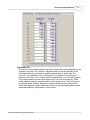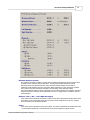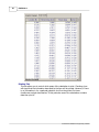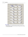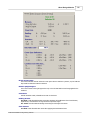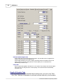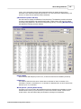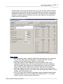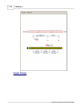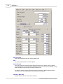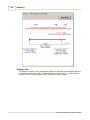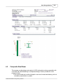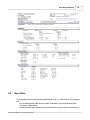
1
Structural Engineering Library
Version 5.8
by Michael D. Brooks, S.E., P.E.
A product of
ENERCALC, INC.
ENERCALC
©1983-2003 ENERCALC Engineering Software
All rights reserved. No parts of this work may be reproduced in any form or by any means - graphic, electronic, or
mechanical, including photocopying, recording, taping, or information storage and retrieval systems - without the
written permission of the publisher.
Products that are referred to in this document may be either trademarks and/or registered trademarks of the
respective owners. The publisher and the author make no claim to these trademarks.
While every precaution has been taken in the preparation of this document, the publisher and the author assume no
responsibility for errors or omissions, or for damages resulting from the use of information contained in this document
or from the use of programs and source code that may accompany it. In no event shall the publisher and the author be
liable for any loss of profit or any other commercial damage caused or alleged to have been caused directly or
indirectly by this document.
Publisher
ENERCALC, INC.
Managing Editor
Michael D. Brooks, S.E., P.E.
ENERCALC Engineering Software
Post Office Box 188
Corona del Mar, CA 92625
(949) 645-0151
(800) 424-2252
Fax: (949) 645-3881
Technical Services: (949) 645-0441
Sales: [email protected]
Tech Support : [email protected]
Web : www.enercalc.com
Vesion 5.8 User's Reference
December 2003
Newport Beach, CA
Contents
I
Table of Contents
Foreword
1
Part I Welcome
5
Part II Structural Analysis Modules
8
1 Single Span Beam
...................................................................................................................................
Analysis
9
2 Beam on Elastic
...................................................................................................................................
Foundation
22
3 Rigid Diaphragm
...................................................................................................................................
Torsional Analysis
35
4 Section Properties
................................................................................................................................... 46
5 Pole Formula
................................................................................................................................... 53
6 Pile Group Load
...................................................................................................................................
Distribution
61
7 Multi-Story Wind
...................................................................................................................................
Load Analysis
68
8 Multi-Story Seismic
...................................................................................................................................
Load Analysis
77
9 Multi-Story Column
...................................................................................................................................
Load Analysis
85
Part III Wood Design Modules
92
1 Multi Span Timber
...................................................................................................................................
Beam
93
2 Timber Beam
...................................................................................................................................
& Joist Design
107
3 General Timber
...................................................................................................................................
Beam
117
4 Series of Cantilevered
...................................................................................................................................
Beams
134
5 Timber Column
................................................................................................................................... 153
6 Plywood Shear
...................................................................................................................................
Wall
165
7 Horizontal ...................................................................................................................................
Plywood Diaphragm
180
8 High-Load ...................................................................................................................................
Plywood Diaphragm
193
9 Timber Ledger
................................................................................................................................... 206
10 Bolt Group...................................................................................................................................
in Timber Member
215
Part IV Steel Design Modules
224
1 Multi-Span ...................................................................................................................................
Steel Beam
225
2 Single Span
...................................................................................................................................
Steel Beam
242
3 Steel Beam...................................................................................................................................
w/Torsion
260
4 Steel Column
................................................................................................................................... 279
5 Composite...................................................................................................................................
Steel Beam
295
6 Base Plate ................................................................................................................................... 321
7 Bolt Group................................................................................................................................... 332
©1983-2003 ENERCALC Engineering Software
I
II
ENERCALC
©1983-2003 ENERCALC Engineering Software
Foreword
This software system was designed and developed to give the practicing
Structural Engineer a tool to rapidly perform structural analysis and design
of building components.
The design philosophy has remained the same for the last 20
years......provide software that is a "fill-in'the-blanks" tool with instant
recalculation and review of the results.
We thank the thousands of engineers who have
purchased ENERCALC software over the last two
decades helping this software develop to where it is today.
©1983-2003 ENERCALC Engineering Software
Part
I
Welcome
1
5
Welcome
Welcome To The Structural Engineering Library
You've chosen one of the most respected Structural Engineering software packages
available today. In continuous development since 1983 , Version 5.8 is the culmination of
years of development and refinement from suggestions of engineers worldwide.
This document provides detailed documentation for all the modules contained in Vesion
5.8 of the Structural Engineering Library.
Please refer to Volume I for general information including licensing, installation, usage
isntructions, and a sample session.
©1983-2003 ENERCALC Engineering Software
Part
II
8
2
ENERCALC
Structural Analysis Modules
The programs in this section provides mostly analysis capabilities. Design in a
particular material is not provided.
Single Span Beam Analysis
Single Span Beam Analysis analyzes single span beams with cantilevers and a variety of
end restraints. Up to 30 point, moment, and uniform/trapezoidal loads can be applied.
Reactions, shears, moments, deflections, and graphic diagrams are given.
Beam on Elastic Foundation
Beam on Elastic Foundation provides all of Hetenyi's and Roark's work in one fast
program. A beam may have any combination of free, guided, pinned, fixed, and
semi-infinite supports. Up to 23 point, moment, and uniform/trapezoidal loads may be
applied. Shear, moment, deflection, rotations and graphic diagrams given.
Torsional Analysis of Rigid Diaphragms
Torsional Analysis of Rigid Diaphragms can calculate the center of rigidity, torsional
moments, minimum eccentricities, and give resultant force to attached walls oriented at
any angle. A stiffness approach is used to generate matrices which are solved for forces.
End fixity combination and elastic modulus can be varied for each wall and all cases of
eccentricity are considered.
General Section Properties
General Section Properties can determine area, neutral axes, inertia, fiber distances,
section modulus, and radii of gyration for sections combining up to 11 bar/pipe shapes
and 3 rolled steel sections.
Pole Footing Design
Pole Footing Design determines required embedment depths for shaft type footings with
shear and moment applied at ground surface, with or without lateral surface restraint.
Pile Group Load Distribution
Pile Group Load Distribution distributes a single vertical load to a maximum of ten piles
using direct distribution and skew bending theory.
Multi-Story Seismic Force Distribution
Multi-Story Seismic Force Distribution gives story shears and moments on a multi-story
structure by vertically distributing base shear on the structure using '94 UBC code.
Multi-Story Wind Force Distribution
Multi-Story Wind Force Distribution gives story shears and moments on a multi-story
structure by vertically distributing '88 UBC wind loads and modification factors.
Multi-Story Column Load Summary
©1983-2003 ENERCALC Engineering Software
Structural Analysis Modules
9
Multi-Story Column Load Summary provides a tabular format for accumulating area loads
on multi-story columns. Loads may be varied per floor and reduction factors considered.
2.1
Single Span Beam Analysis
Overview
This program provides analysis of single span beams with a variety of loading and
support conditions. Maximum moments, shears, reactions, and deflections are given. The
basic ability of this program is also contained in the various beam design programs in the
steel, concrete, and timber divisions. This program performs a more detailed analysis and
offers more loading options than most of the design programs.
A single span beam with optional cantilevers can be analyzed, and the end supports can
be modified to give almost any configuration.....simple supports, propped cantilever, fixed
at both ends, pure cantilever, or double cantilever.
Loads that can be applied are extensive. Uniform, partial length, trapezoidal,
concentrated, and moment type load can be entered. For partial length and trapezoidal
loads, entry is very simple by just entering the start and end magnitudes and locations.
The program uses the locations to determine how the load is applied to center and
cantilever spans.
NOTE! All load locations are in reference to the LEFT support. Distances are positive
toward the right support, and negative over the left cantilever. The program also
provides a QUERY section, allowing you to enter locations along the span where you
would like to investigate the conditions.
©1983-2003 ENERCALC Engineering Software
10
ENERCALC
Assumptions and Limitations
· The program calculates all values by dividing the beam up into 500 sections and
performing moment-area integration for deflections. Calculated values generally will
be within 1/5000th of the actual number.
Example
The data entry for this example is shown in the screen captures that accompany the Data
Entry Tabs and Results & Graphics Tabs sections to follow. The example is for a
double-cantilevered beam with loads applied to center span and cantilever. Because this
program does not do automatic calculations for multiple locations of live load only one set
of results are given. Here is a basic sketch of the geometry and loading:
©1983-2003 ENERCALC Engineering Software
Structural Analysis Modules
11
Data Entry Tabs
This set of tabs provides entries for all input in this calculation. While you are entering
data and switching between these tabs you can view the desired resulting information on
the tabs on the right-hand side of the screen (calculated values, sketches, diagrams,
etc.). A recalculation is performed after any entry data is changed. After each data entry
you can view the results on the right-hand set of tabs.
General Tab
©1983-2003 ENERCALC Engineering Software
12
ENERCALC
Center Span, Left Cantilever, Right Cantilever
Enter the span lengths for center span and cantilevers. When an end fixity is specified as Fixed, any
entry for cantilever length or loads that extend past the fixed support will be ignored. Distributed loads
that extend past the fixed support will simply be truncated.
End Fixity
This entry enable you to specify the end fixity combination for the beam. The order of the words is
refers to the left-right ends of the beam.
· "Pin" means that the beam end is free to rotate but fixed against X or Y (horizontal or vertical)
movement.
· "Free" means that the end is completely free to move in all directions....basically a cantilever end.
· "Fixed" is like "Pin" but rotation is also prevented......just as if the beam end were buried in stone.
Inertia & Elastic Modulus
Entry of both these items is required to for the program to calculate deflections. If one or both of
these entries is zero deflections will be "0.0".
Uniform Tab
This tab provides entries for you to apply full-length uniform loads to the center span
and cantilevers. Positive values act with the force of gravity and deflect a beam
downward resulting in compression on the top fiber.
Point Tab
This tab provides entries so you can enter up to 14 point loads. The "Location" is the
distance from the left support to the location of the point load. If the "Location" value
is negative then it is on the left cantilever. If the value exceeds the center span length
then it is on the right cantilever. Cases where negative Locations are entered with no
left cantilever or a "Fixed" left support are ignored. Similar behavior happens for
Location values that are longer than the Center Span distance. Positive values act with
the force of gravity and deflect a beam downward resulting in compression on the top
fiber.
©1983-2003 ENERCALC Engineering Software
Structural Analysis Modules
13
Trapezoidal Tab
Up to 8 full or partial length uniform loads with varying start & end magnitudes can be
specified on this tab. The "Left/Start" magnitude refers to the left hand side of the
load. Magnitudes can be positive or negative values at both or either ends. The
"Location" is the distance from the left support to the location of the Startpoint or
Endpoint of the load. If the "Location" value is negative then it is on the left cantilever.
If the value exceeds the center span length then it is on the right cantilever. Cases
where negative Locations are entered with no left cantilever or a "Fixed" left support
are ignored. Similar behavior happens for Location values that are longer than the
Center Span distance. Positive values act with the force of gravity and deflect a beam
downward resulting in compression on the top fiber.
©1983-2003 ENERCALC Engineering Software
14
ENERCALC
Moment Tab
This tab provides entries so you can enter up to 8 moments. The "Location" is the distance from
the left support to the location of the point load. If the "Location" value is negative then it is on
the left cantilever. If the value exceeds the center span length then it is on the right cantilever.
Cases where negative Locations are entered with no left cantilever or a "Fixed" left support are
ignored. Similar behavior happens for Location values that are longer than the Center Span
distance. Positive values act with the force of gravity and deflect a beam downward resulting in
compression on the top fiber.
©1983-2003 ENERCALC Engineering Software
Structural Analysis Modules
15
Query Tab
This tab enables you to enter specific locations on the beam span and have the moment, shear, and
deflection given. The accuracy of these values is to the nearest 1/500th of the span.
©1983-2003 ENERCALC Engineering Software
16
ENERCALC
Results & Graphics Tabs
This set of tabs provides the calculated values resulting from your input on the "Data
Entry Tabs". Because a recalculation is performed with each data entry, the information
on these tabs always reflects the accurate and current results, problem sketch, or
stress/deflection diagram.
Results Tab
This tab contains the resulting calculated values for the beam analysis.
©1983-2003 ENERCALC Engineering Software
Structural Analysis Modules
17
Maximum Moment & Location
The maximum moments at location is shown with it's location measured from the left support. This is
an absolute value maximum with the sigh intact. The actual span lengths increments used to
determine the accuracy depend upon the center span and cantilever lengths. A beam with no
cantilevers will be divided up unto 500 increments. When cantilevers are used, each span is divided
into a portion of the 500 increments according to its percentage of the total beam length.
This is the maximum positive moment (compression at top of beam) between the supports. The entire
length of the beam is scanned, and if compression occurs over a support due to a cantilever this will
be included also.
Moments....Max.+, Max. -, Left & Right End Support
These values are the maximum and minimum values for the center span and the actual moment at the
end support. M The entire length of the beam is scanned, and if compression occurs over a support
due to a cantilever this will be included also.
Shears
These values are the maximum shear at each support. This value is determined by checking two items:
· At ends without cantilevers or with fixed ends, the end shear equals the support reaction.
©1983-2003 ENERCALC Engineering Software
18
ENERCALC
· At ends with cantilevers, the end shear is calculated by determining the total of all loads acting on
the cantilever, or by the reaction less loads acting on the cantilever).
Reactions
These are the calculated vertical reactions at each support from the given loads.
Maximum Deflections
When both moment of inertia and elastic modulus are non-zero, this area displays the beam
deflections for center and cantilever spans (as applicable). All 250 span locations are checked for
maximum deflection and both the location and deflection are given.
Sketch Tab
This tab provides a sketch of the beam with loads and resulting values shown.
Diagrams Tab
This displays a moment, shear, and deflection diagram for the beam with the applied loads and
end conditions. Note the two tabs...."Graphic Diagram" and "Data Table". The Data Table tab
provides the entire internal analysis at the 1/500th points within the beam.
©1983-2003 ENERCALC Engineering Software
Structural Analysis Modules
©1983-2003 ENERCALC Engineering Software
19
20
ENERCALC
Printing Tab
This tab allows you to control which areas of the calculation to print. Checking a box
will signal that the information described by the item will be printed. However, if there
is no information in for a particular selection it will not be printed. So these
checkboxes are best described as "If this particular area of the calculations contains
data then print it".
©1983-2003 ENERCALC Engineering Software
Structural Analysis Modules
Sample Printout
©1983-2003 ENERCALC Engineering Software
21
22
2.2
ENERCALC
Beam on Elastic Foundation
This program provides analysis of solid beams continuously supported by an elastic
material. Typical applications are for concrete beams supporting uniform and
concentrated building loads, transferring the loads to the underlying soil.
This program is based upon the elastic beam formulas presented in Formulas for
Stress and Strain, 5th Ed., by Raymond J. Roark and Warren C. Young (Article 7.5 and
©1983-2003 ENERCALC Engineering Software
Structural Analysis Modules
23
Table 7 & 8) and Beams on Elastic Foundation by M. Hetenyi, University of Michigan
Press, 1946.
NOTE! THIS PROGRAM ASSUMES ELASTIC BEAM IS ALWAYS IN COMPRESSION. No
provision is made when the beam has upward deflection. In this instance the beam is
actually "pulling" the soil upward instead ignoring the soil/beam interaction. This is so
because of the nature of the equations used.
The established formulas have been formulated into computer code that is used by this
program, which can analyze beams considering:
· Left end free, guided, pinned, or free.
· Right end free, guided, pinned, free, or infinite.
· Up to 7 uniform loads, 11 concentrated loads, and 5 applied moments.
Assumptions and Limitations
The flexibility of the beam in relation to the spring constant of the soil is limited. In the
program you will see the item "Beta * Length". The value Beta is a measure of the
beams flexibility and is equal to:
©1983-2003 ENERCALC Engineering Software
24
ENERCALC
(Width * Subgrade Modulus / (4 * EI) ) ^1/4
According to the reference text when the value Beta * Length > 6.0 the beam is so
flexible that the behavior changes. In this case the program displays a message and no
results are given.
Example
The data entry for this example is shown in the screen captures that accompany the Data
Entry Tabs and Results & Graphics Tabs sections to follow.
Data Entry Tabs
This set of tabs provides entries for all input in this calculation. While you are entering data
and switching between these tabs you can view the desired resulting information on the
tabs on the right-hand side of the screen (calculated values, sketches, diagrams, etc.). A
recalculation is performed after any entry data is changed. After each data entry you can
view the results on the right-hand set of tabs.
General Tab
This tab collects all the analysis information except loading.
©1983-2003 ENERCALC Engineering Software
Structural Analysis Modules
Beam Span
Enter the length of the beam between end supports.
Depth & Width
Enter the beam depth and width to be used for calculation of moment of inertia.
End Fixities
Free : Indicates the beam end has no vertical, horizontal, or rotational restraint.
Guided : Indicates the beam end has horizontal restraint, but is not allowed to rotate or move
horizontally.
Pinned : Indicates the beam end is free to rotate, but cannot translate vertically or horizontally.
Fixed : Indicates the beam end is fully restrained against vertical and horizontal translation and
cannot rotate.
Elastic Modulus
Elastic modulus of the beam's material. Steel is 29,000 ksi; concrete is 57,000 * sqrt(f'c)
©1983-2003 ENERCALC Engineering Software
25
26
ENERCALC
Subgrade Modulus
The compressive modulus (commonly called the K-Value) of the supporting material. A Soil Engineer,
based upon field testing of the soil typically supplies this value. The units for this number are pounds
per square inch per inch of deflection, or just an ordinary spring constant.
I-Gross
Calculated using Width * Depth3 / 12 for rectangular sections
Beta * Length
Beta is a measure of the difference in flexural stiffness between the beam and foundation. beta =
(Beam Width*Subgrade Modulus) / ( 4.0 * E * I)) ^ .25. See the major section "Assumptions &
Limitations" for more information.
Load Combinations
These entries define load factors to be applied to the loads entered on the next three tabs. You can
use these to build ACI type factored load combinations for the analysis run. There is one load factor
for Dead, Live and Short Term loads. The "Overall" factor is applied to the summation of the three.
The "Current Load Combination" selection tells the program which loads to use. In our example you
can see that "Dead, Live & Short Term Loads" has been selected. This means that all loads of all
types will have the factors applied to them and then the overall factor applied. In this example the final
load applied to the beam is:
(1.40 * DL + 1.70 * LL * 1.55 * ST) * 0.83
Uniform Loads Tab
This load is a uniform intensity load applied from SLoc (start distance) to ELoc (end distance).
The values for dead, live, and short-term loads are combined according to Load Combination. If
ELoc is specified greater than Span (except for an Infinite right support), then the excess
distance is ignored.
©1983-2003 ENERCALC Engineering Software
Structural Analysis Modules
27
Point Loads Tab
Up to 11 point loads can be applied to the beam, with the dead, live, and short-term
components combined according to Load Combination. If the ELoc distance is specified greater
that Span (except for Infinite right supports), the load is ignored.
©1983-2003 ENERCALC Engineering Software
28
ENERCALC
Moments Tab
The user may apply up to 5 concentrated moments at any location on the beam. The sign
convention follows the right hand rule, where a positive moment applies a torque to the beam
in a counter-clockwise direction.
©1983-2003 ENERCALC Engineering Software
Structural Analysis Modules
29
Results & Graphics Tabs
This set of tabs provides the calculated values resulting from your input on the "Data
Entry Tabs". Because a recalculation is performed with each data entry, the information
on these tabs always reflects the accurate and current results, problem sketch, or
stress/deflection diagram.
Results Tab
©1983-2003 ENERCALC Engineering Software
30
ENERCALC
Shear ( Reactions )
Maximum positive and negative shears and the locations where they occur are given by checking the
span at 250th points.
Moments
Maximum positive and negative moments and the locations where they occur are given by checking
the span at 250th points.
Rotation
Maximum positive and negative rotations and the locations where they occur are given by checking the
span at 250th points.
Deflection
Maximum positive and negative deflections and the locations where they occur are given by checking
the span at 250th points.
Soil Pressure
Using the deflection values given above and multiplying by the subgrade modulus gives the soil
pressures. The basis of the calculation is (Spring Force * Distance) = Force. Maximum positive and
©1983-2003 ENERCALC Engineering Software
Structural Analysis Modules
31
negative soil pressures and the locations where they occur are given by checking the span at 250th
points.
Values @ Beam Ends
· Reactions Ra and Rb (left and right supports) are given for ends which have Pinned and Fixed
support restraints.
· Rotations at Left and Right (left and right ends supports) are given for ends which have Free,
Pinned, and Infinite support restraints.
· Moments Ma and Mb (left and right ends supports) are given for ends which have Guided and Fixed
support restraints.
· Deflections Da and Db (left and right ends supports) are given for ends which have Free and Guided
support restraints.
Sketch Tab
This tab provides a sketch of the beam with loads and resulting values shown. Using the [Print
Sketch] button will print the sketch in large scale on a single sheet of paper.
Diagrams Tab
This displays a moment, shear, and deflection diagram for the beam with the applied loads and
end conditions. Note the two tabs...."Graphic Diagram" and "Data Table". The Data Table tab
provides the entire internal analysis at the 1/500th points within the beam.
©1983-2003 ENERCALC Engineering Software
32
ENERCALC
©1983-2003 ENERCALC Engineering Software
Structural Analysis Modules
33
Printing Tab
This tab allows you to control which areas of the calculation to print. Checking a box will signal
that the information described by the item will be printed. However, if there is no information in
for a particular selection it will not be printed. So these checkboxes are best described as "If
this particular area of the calculations contains data then print it".
©1983-2003 ENERCALC Engineering Software
34
ENERCALC
Sample Printout
©1983-2003 ENERCALC Engineering Software
Structural Analysis Modules
2.3
35
Rigid Diaphragm Torsional Analysis
This program provides horizontal force distribution analysis for a rigid diaphragm laterally
supported by up to 60 walls. X and Y axis forces may be applied to a center of mass
location, and that force distributed to all walls after the rotational stiffness analysis has
been completed.
All lateral forces are distributed to each wall on the basis of relative rigidities and wall
locations. Lateral shear forces, induced torsional forces, and minimum eccentricity are
considered after determining the location of the center of rigidity. The user may enter
dimensions for walls of homogeneous materials for use in calculating relative stiffness's.
The program provides analysis for one level only. For structures where walls are
©1983-2003 ENERCALC Engineering Software
36
ENERCALC
symmetrically placed on many levels, a calculation may be performed for each level and
results added to determine shears and overturning moments for each wall. When
determining center of mass (where the lateral force is applied) on successively lower
levels when walls are NOT all in line, a new center of mass position should be calculated
based upon wall forces acting from the diaphragm from the level above and combined
with the force at that level.
Basic Usage
· The most important step for successful use of this program is to properly enter the
X and Y location of the center of rigidity of each wall and the wall angle.
· For rectangular walls, the center of the wall's rigidity will be at the centroid of the
section.
· The wall angle is measured with respect to the centerline of the length
measurement (long dimension). 0deg and 180deg defines the wall's angle as parallel
to the X-axis. 90deg and 270deg defines the wall as being parallel to the Y-axis. The
angle increases positively in a counterclockwise direction.
· You will also note that the wall table allows up to 60 walls to be entered. When you
have less than 60 (which will be typical), make sure all information for each unused
©1983-2003 ENERCALC Engineering Software
Structural Analysis Modules
37
row is zero, which signals the program that no wall is being used on that row.
· Lateral shears are typically the force at the diaphragm level due to wind or seismic
forces at that level. Distance to Center of Mass specifies the X/Y location where the
lateral shears act. If lateral forces must be added to the diaphragm from the level
above or below, you must combine all forces to calculate an adjusted mass
application point. Maximum Dimensions are used to calculate the minimum
additional eccentricity that will be added and subtracted from the calculated
eccentricity to calculate governing forces to each wall.
· Wall Thickness, Length, Height dimensions of each wall providing lateral support to
the diaphragm are required, and together with the elastic modulus entry fully define
the relative stiffness of the wall.
· The Elastic Modulus does not have to be an exact number if all the walls are of
identical construction. The most typical use is to enter 1" here.
· X & Y Distances for each wall design the center of plan-view stiffness of each wall.
This location will be used when combining all wall stiffness's and calculating the
overall center of rigidity for all walls acting as a system.
· Enter the inclination angle of each wall along its length axis. Enter all angles as
positive.
· Enter the fixity condition that will best describe the wall's top and bottom rotational
restraint. FP (Fix/Pin) indicates that one end is free to rotate while the other is fixed,
while FF (Fix/Fix)indicates that both ends cannot rotate and results in double
curvature.
Unique Features
This program uses a numerical approach to determine center of rigidity location and to
distribute lateral forces to each wall. Because walls may be located at any angle, a
rigorous stiffness analysis is made calculating each wall's stiffness about both axes and
combining the stiffness's of all the walls to determine a center of rigidity location.
Assumptions & Limitations
Because this program performs a very complex stiffness matrix analysis for all walls, the
traditional method of listing separate components of direct and torsional shears is not
applicable. Also, the program internally adds and subtracts the additional accidental
eccentricity (based on both maximum dimensions) about each axis to calculate maximum
force to each wall. The results in one final force value being displayed for each wall.
Coordinate System
Please note that a STRICT X-Y coordinate system should be used to ensure that the
analysis is properly carried out. When setting up an X-Y coordinate axis, please follow the
standard Cartesian model with the diaphragm located such that X increases to the right
and Y increases up. Unless another method is necessary, this will perform very well (but
the program can handle variations).
©1983-2003 ENERCALC Engineering Software
38
ENERCALC
Example
The data entry for this example is shown in the screen captures that accompany the Data
Entry Tabs and Results & Graphics Tabs sections to follow. Here is the sketch showing
the angular orientation of the walls. Please see the table of wall input values for the exact
locations.
Data Entry Tabs
This set of tabs provides entries for all input in this calculation. While you are entering
data and switching between these tabs you can view the desired resulting information on
the tabs on the right-hand side of the screen (calculated values, sketches, diagrams,
etc.). A recalculation is performed after any entry data is changed. After each data entry
you can view the results on the right-hand set of tabs.
General Tab
©1983-2003 ENERCALC Engineering Software
Structural Analysis Modules
39
Loading : XX Shear, YY Shear
Calculate the total lateral force to be applied at the center of mass of the diaphragm. We have
provided individual entries for each direction, to allow for different lateral forces in each direction. For
multi-story buildings in seismic and/or high wind areas, the building code specifies a non-linear
distribution of base shear force (for multiple levels) which should be considered. You can use the Multi
Story Seismic Force Distribution and Multi Story Wind Force Distribution programs to help you with this
analysis.
Load Application
Forces Act Separately : The maximum applied shear value will be the maximum force from each
shear force acting separately along each axis.
Forces Act Together : Both XX and YY axis shear forces will be applied to the diaphragm
simultaneously to calculate the maximum forces to each wall.
Minimum Applied Shear Eccentricity
This specifies the minimum accidental (additional) eccentricity that should always be used
for determining torsional forces on the diaphragm. Entering 5" specifies 5% minimum
accidental eccentricity for a direction. For a 100' maximum dimension this would result in a
5'-0" minimum eccentricity between center of mass and center of rigidity.
Distance to Center of Mass
Enter the X and Y distance from the datum point to where the Shear Force is applied. The center of
rigidity (+/-5% accidental eccentricity) is compared with this location to determine overall diaphragm
©1983-2003 ENERCALC Engineering Software
40
ENERCALC
torsions.
Maximum Dimensions
This value represents the diaphragm's maximum dimension along the X and Y-axis, and is used to
determine the minimum eccentricity of the applied shears by multiplying it by the "Minimum Applied
Shear Eccentricity".
Wall Data Tab
This tab is used as the main data entry location for all wall data. The entry items at the bottom
of the screen let you edit the highlighted item in the list directly. To Add a wall you must use
the
button.
Add, Change Delete Buttons
These buttons control the table of values for all the walls. Each button works on the wall line currently
highlighted. When pressing Add or Change a window is displayed very similar to the one shown below.
Using this window you can specify the information for the wall.
©1983-2003 ENERCALC Engineering Software
Structural Analysis Modules
41
Since the program considers each wall to be of one material with uniform properties throughout you
simply need to specify the Thickness, Height, Width, and Elastic Modulus to specify the stiffness of the
wall.
The "Length" dimension is used by the program as the axis to report shear along the wall. Although
the program calculates shear both along and perpendicular to the wall (width direction) the length is
assumed to be what you are interested in and the final shear results are given along that direction.
Thickness
This is the thickness of the wall and should be the smaller plan view cross sectional dimension of the
wall.
Length
This is the length of the wall and should be the larger plan view cross sectional dimension of the wall.
This is the length which would normally be considered to be stiffer and brace the diaphragm against
lateral forces. Each wall's thickness (and length) is used to calculate the moment of inertia
about each axis, depending on how the Fixity item is specified (see below). This dimension
is perpendicular to the axis used to measure the wall angle.
NOTE..... Before examining components of each wall's stiffness about each axis, for calculation of the
wall stiffness matrices, deflection constants are calculated using IMAJOR and IMINOR. The typical
deflection equation:
P/E[h3/(inertia *value) + 2.64h/A]
will set value = 12 for Fixed/Fixed walls and 3 for Fixed/Pinned walls.
Height
This is the height of the wall from the next lower datum point. Because the program does not "know"
that there is any consistent reference elevation on the floor below you are free to enter a different
height.
X Distance to C.G., Y Distance to C.G.
This is the distance from the center of resistance of the wall from your datum point. The center of
resistance is the dimensional plan view center of the wall.
Wall Angle CCW
©1983-2003 ENERCALC Engineering Software
42
ENERCALC
This is the rotation of the wall's length axis. It is measured in degrees rotated counter-clockwise from
the "X" axis which is assumed to be horizontal to the model. For example, a 12" thick x 5'-0" long wall
(in plan view) that is rotated 90 degrees is oriented up & down and is parallel with the "Y" axis.
Elastic Modulus
This is the elastic modulus of the wall. You can modify this value to "play" with a wall's stiffness that
will result in a linear effect on the walls stiffness.
Wall End Fixity
Select Fixed-Fixed when the wall's top and bottom end rotations are completely restrained by
boundary elements (such as by walls above, large footing, etc.). When one end of the wall is free to
rotate select Fixed-Pinned. This entry will modify the calculation of each wall's rigidity (1/deflection).
Modeling hints
You can use this program to model all types of shear resisting elements. Note that Thickness and
Elastic modulus have a direct linear effect on the wall stiffness. The length and height values have a
non-linear effect (see stiffness equations to follow).
Results & Graphics Tabs
This set of tabs provides the calculated values resulting from your input on the "Data
Entry Tabs". Because a recalculation is performed with each data entry, the information
on these tabs always reflects the accurate and current results, problem sketch, or
stress/deflection diagram.
Results Tab
This tab shows the major calculated values for the system of walls entered.
Distance to Center of Rigidity
This is the calculated distance from the datum (0,0) point to the center of translational rigidity of the
system of walls.
The center of rigidity is calculated by:
· Forming a stiffness matrix for each wall. This matrix models each wall's stiffness about its length and
©1983-2003 ENERCALC Engineering Software
Structural Analysis Modules
43
thickness axis.
· Solve each matrix for wall rigidities
· Solve simultaneous equations for X and Y locations of center of rigidity.
Accidental Eccentricity
This value is the entered maximum X and Y dimensions multiplied by the minimum eccentricity
value/100 =(CR-CM)+ Accidental
Using the calculated center of rigidity and accidental torsion values that cause maximum wall loads,
these are the eccentricities used to calculate X-X and Y-Y axis torsions.
Torsional Moments from Y-Y Shear
Using the specified Y-Y applied shear force and applying it at an eccentricity equal to :
Center of Mass - Minimum Eccentricity - Distance to Center of Rigidity)
the applied torsional moments on the diaphragm are calculated. These torsional moments are then
used to determine the force along the length axis of the wall needed to resist it using the calculated
stiffness's of all walls in the system.
Wall Forces Tab
This is a summary of information table that shows wall number, eccentricity of wall's resisting
center to diaphragm's center of rigidity, and the direction and torsional shear components
calculated for the wall.
These components are then analyzed in all of their combinations to see which combination
gives the maximum force parallel to the "length" of the wall.
Eccentricity
This is the distance from the walls geometric center (entered as input as "Wall C.G. Location") to the
calculated "Center of Rigidity" of the system of walls you have entered.
Direct Shears & Torsional Shears
Max. Shear Along Length
Considering the center of rigidity for the entire system of walls, the maximum force to each wall is
calculated by:
· Using the individual wall stiffness values to calculate a polar moment of inertia.
· Using the applied shear force in each direction and wall stiffness's, to solve for the X and Y
deflections of the overall diaphragm system.
©1983-2003 ENERCALC Engineering Software
44
ENERCALC
· Calculating two torsional moments for the X and Y shear force, and determining which will yield the
greatest force to each wall.
· Using those torsions and the polar moment of inertia to calculate diaphragm rotations.
· Solving the forces in each wall that would be necessary to produce the wall deflection consistent
with diaphragm rotation at the wall's location.
Because of the stiffness matrix approach for determining rigidities and deflections, the actual number
of forces calculated for each wall is 32....one for each axis (2), one for each applied load (2), and two
for each accidental eccentricity (8). This equals 2 * 2 * 8 = 32 forces for each wall.
For each wall, the force applied to the wall in each direction is summarized as direct and torsional
shear, with the governing eccentricity of the applied load that created the torsional shears shown.
The table is difficult to understand when loads are applied along both axis at once, so we recommend
only applying a load along one axis for each run and printout.
Sketch Tab
This tab provides a sketch of the beam with loads and resulting values shown. Using the [Print
Sketch] button will print the sketch in large scale on a single sheet of paper. The buttons at the
bottom of the tab control the display of additional information.
©1983-2003 ENERCALC Engineering Software
Structural Analysis Modules
Sample Printout
©1983-2003 ENERCALC Engineering Software
45
46
2.4
ENERCALC
Section Properties
This program determines section properties for built up sections with rectangles, hollow
circles, solid circles, and standard AISC steel sections.
AISC sections can be recalled from the database files and included in the built-up section.
W and C sections from the 6th, 7th, 8th, and 9th edition handbooks are available. They
can be rotated 90 deg, 180 deg, or 270270 deg desired
Calculated section property values are area, moments of inertia, center of gravity
location, extreme fiber distances, section moduli, and radius of gyration.
©1983-2003 ENERCALC Engineering Software
Structural Analysis Modules
47
Basic Usage
Before starting data entry, be sure you have set up an X/Y coordinate system to
consistently reference all component locations.
For each rectangular shape, enter the height, width, and center of area from the
datum.
Circular sections are entered by specifying the outside radius and thickness. The radius
is measured from the center to the outside of the circular shape. Set thickness to zero
for solid sections, or non-zero for hollow pipes.
For AISC sections, this distance will locate the section's centroid position. The program
knows the centroid location of AISC members with respect to their own extreme fiber
locations. However, you need to enter the location of the shape's actual centroid in
relation to the other rectangular and/or circular shapes. Be careful, as this can be
tricky when entering channels, angles, and tee sections that are rotated.
This program will allow entry of solid circular or pipe sections. When a solid circular
section is to be used, the user simply enters 0" for thickness of the circular shape.
A unique feature allows the user to specify whether the X and Y axes of AISC sections
should be turned +/-90 degrees.
Assumptions & Limitations
The program operates on a simple calculation procedure:
· Calculate the moment of inertia of each shape,
· Calculate the neutral axis of the group of shapes, and
©1983-2003 ENERCALC Engineering Software
48
ENERCALC
· Calculate the moment of inertia of the group using I + A*D2 equations.
More complex analysis such as polar moment of inertia, plastic moduli, and buckling
constants are beyond the scope of the program.
To calculate the section modulus, the program checks for the most distant portion of any
shape from the calculated neutral axis on all four sides. The appropriate X-X or Y-Y
moment of inertia is then divided by this distance (fiber distance) to get the section
modulus for each of the four sides.
Example
The data entry for this example is shown in the screen captures that accompany the Data
Entry Tabs and Results & Graphics Tabs sections to follow.
Data Entry Tabs
This set of tabs provides entries for all input in this calculation. While you are entering data
and switching between these tabs you can view the desired resulting information on the
tabs on the right-hand side of the screen (calculated values, sketches, diagrams, etc.). A
recalculation is performed after any entry data is changed. After each data entry you can
view the results on the right-hand set of tabs.
General Tab
This tab provides all the data entry locations. It is divided into two areas: (1) to define rectangular and
circular shapes and (2) To add AISC rolled sections.
©1983-2003 ENERCALC Engineering Software
Structural Analysis Modules
49
General Shapes
This area contains small tabs #1 thru #10 which each are used to define a rectangular or circular item.
The screen image above shows data entry for a rectangular section. By changing the drop-down box
to "Circular" you would see the entry prompts below:
Each shape input provides for the size of the item and the X & Y distance from a datum point where
the CENTER OF GRAVITY of the section is located.
©1983-2003 ENERCALC Engineering Software
50
ENERCALC
Also note that for "Circular" section types you can enter the inside diameter thus allowing solid circles
and hollow pipes.
Rectangles
Enter the dimensions of square or rectangular shapes to be included in the analysis on each line. Also,
enter the location of the center of gravity of this shape with respect to a datum point you have chosen.
Distances from the datum can be positive or negative.
Circular Sections
Enter the dimensions of solid circular or hollow pipe shapes to be included in the analysis in this
location. Also, enter the location of the center of gravity of this shape with respect to a datum point
you have chosen. Distances from the datum can be positive or negative. The Radius entry means the
outside radius.
To specify a solid circular section, set the entry for Thickness equal to zero. This will signal the
program that the circular section is solid. For any other circular shape that has a hollow circular core,
enter the wall thickness (not the inner diameter).
Distance to C.G.
This distance locates the center of area of each shape with respect to a datum. Locations may be
positive or negative.
AISC Rolled Shapes
In the lower area of the tab you see five smaller tabs that provide data entry locations for up to five
rolled AISC sections. To specify a section t be used either type in the section name in the entry area
and press the [Tab] key -or- use the [Section] button to use the built in steel section database.
Angle 0/90 deg.
This entry allows you to orient the section at 0, 90, or -90 degrees. 0 degrees specifies the typical
orientation with the Y-Y axis vertical. 90 degrees rotates the section counterclockwise 90 degrees. -90
degrees will rotate the section clockwise 90 degrees (to allow channels to be oriented open end
down).
Results & Graphics Tabs
This set of tabs provides the calculated values resulting from your input on the "Data
Entry Tabs". Because a recalculation is performed with each data entry, the information
on these tabs always reflects the accurate and current results, problem sketch, or
stress/deflection diagram.
©1983-2003 ENERCALC Engineering Software
Structural Analysis Modules
51
Total Area
The total area of all defined shapes, including the area of any AISC sections which have been included
in the analysis.
X Distance to Center of Gravity
Using the locations of the center of gravity of each entered shape and AISC section data, static
moments are taken about each X and Y datum and the center of gravity distance from the datum is
determined.
Edge Distance from C.G.
This is the distance from the Center of Gravity (more properly the center of area) of the composite
section to the most extreme fiber in each direction.
Inertia : Ixx & Iyy
The overall moment of inertia of the composite section is determined by applying the following
equation to all the defined shapes:
I-xx + (A * dy2) and I-yy + (A * dx2)
where d = Distance from the shape's C.G. to the overall C.G. of the composite section.
Radius of Gyration
The radius of gyration of the composite section is determined using the typical equation: ( Ixx / A )½
and ( Iyy / A )½
Section Modulus : S
These values are the calculated section moduli of the composite section. The values are determined by
dividing Ixx or Iyy by the fiber distances above, below, right, and left of the center of gravity of the
©1983-2003 ENERCALC Engineering Software
52
ENERCALC
section.
Sketch Tab
This tab provides a sketch of the beam with loads and resulting values shown. Using the
[Print Sketch] button will print the sketch in large scale on a single sheet of paper.
Sample Printout
©1983-2003 ENERCALC Engineering Software
Structural Analysis Modules
2.5
53
Pole Formula
This program determines actual soil pressures and required depths for footings primarily
supporting lateral loads. Such footings are commonly called Flagpole footings. Since
applied top moment generates lateral soil pressures that usually govern the design, these
footings typically have a depth/width ratio of 2:1 and greater.
Cases with and without lateral restraint at the ground surface are allowed. Evaluation of
actual and allowable pressures is in accordance with 1994 U.B.C. Section 1806.7.
©1983-2003 ENERCALC Engineering Software
54
ENERCALC
Unique Features
· This program allows you to design up to five pole footings on one calculation sheet.
· You can enter a point lateral load, partial length distributed lateral load, or both, to
apply shear and moment at the top of the footing.
· This program is a straight application of the Uniform Building Code formula
referenced above.
Assumptions & Limitations
· Allowable passive pressure is assumed to increase linearly with depth, up to the
specified maximum.
· When surface restraint is specified, the restraint is assumed to be rigid and able to
resist lateral reactions.
Example
The data entry for this example is shown in the screen captures that accompany the Data
Entry Tabs and Results & Graphics Tabs sections to follow.
©1983-2003 ENERCALC Engineering Software
Structural Analysis Modules
55
Data Entry Tabs
This set of tabs provides entries for all input in this calculation. While you are entering
data and switching between these tabs you can view the desired resulting information on
the tabs on the right-hand side of the screen (calculated values, sketches, diagrams,
etc.). A recalculation is performed after any entry data is changed. After each data entry
you can view the results on the right-hand set of tabs.
General Tab
This tab contains all the date entry items for this calculation.
©1983-2003 ENERCALC Engineering Software
56
ENERCALC
Allowable Passive Pressure
The allowable lateral force the soil can withstand. This value will be increased per foot of vertical
embedment depth. For example, at 4'-0" below the surface allowable lateral pressure entry of 150
psf/ft would be able to resist 150 * 4 = 600 psf.
· Regardless of maximum value entered in the next entry the allowable pressure will not
be raised when the depth of embedment is below 12'-0".
Max Passive
Maximum allowable passive pressure regardless of depth, and load duration factor to be used to
increase the allowable pressures. Per code
Load Duration Factor
The load duration factor will be applied to the allowable lateral passive pressures. This number will
then be used as the allowable pressures used to determine footing embedment.
Pole Shape
©1983-2003 ENERCALC Engineering Software
Structural Analysis Modules
57
Use this section to specify whether the pole is round or square. If the pole is specified as square, the
dimension entered is multiplied by 1.41 to arrive at an equivalent width dimension for calculations.
Pole Diameter / Pole Width
Enter the width or diameter of the footing, and specify whether a round or rectangular footing is used.
Width is measured perpendicular to force direction.
Pole Restraint
Specify whether the footing is free at the ground surface or restrained and cannot rotate. A Restrained
footing indicates that a concrete slab or other rigid element only allows rotation of the top of the
footing without translation. When specifying a restrained footing, you must assure yourself that the
final force required to be restrained at the top can be provided.
When ground surface restraint is present, the lateral pressure value that will govern the
design will be at the base of embedment.
The program will iterate (solving the indeterminate equations) until the minimum embedment depth is
determined.
Applied Loads
Point and Distributed Loads. Two types of loads may be entered; concentrated load applied at some
point above the ground, or a partial length uniform lateral load. The program will combine both
loading's and use the resultant moment and shear force at the ground surface.
Results Tab
©1983-2003 ENERCALC Engineering Software
58
ENERCALC
Moments @ Surface
This moment results from applying both point and concentrated loads to the pole (above soil) at their
respective distances above the soil surface
Total Moment
Total Lateral Load
This force is simply the sum of point and distributed lateral loads applied to the pole.
©1983-2003 ENERCALC Engineering Software
Structural Analysis Modules
59
Without Surface Restraint
Required Depth : Based on the 1988 UBC 1806.7 formulas shown on the next page, the minimum
required embedment depth is calculated to satisfy allowable soil pressures.
For poles not
Depth
A
P
S1
b
h
restrained at surface:
=
A/2 * [ 1 + ( 1 + (4.36*h/A))½ ]
=
2.34 P / ( S1 * b)
=
Applied lateral force, lbs
=
Allowable Lateral passive pressure at 1/3 embedment * LDF
=
Diameter or width of footing or pole
=
Height of point of load application
Actual @ 1/3 Embedment : This is the location of maximum lateral pressure for non-restrained
footings. Considering the applied loads, pole footing dimensions, and calculated length of embedment,
the actual lateral pressure at 1/3 of embedment depth is given here. It is calculated using a modified
version of the formula used to calculate depth of embedment.
Allow. @ 1/3 Embedment : The allowable passive pressure (after application of the load duration
factor) is multiplied by 1/3 the pole embedment, compared with the limiting value, and the smaller
value used. This number is then multiplied by the load duration factor to get the final allowable
pressure at 1/3 embedment.
With Surface Restraint
Required Depth : Based on the formulas to follow, the minimum required embedment depth is
calculated to satisfy allowable soil pressures. Per U.B.C Section 1806.7 :
Depth
=
(4.25 * P * h / ( S3 * b ) )½
P
=
Applied lateral force, lbs
h
=
Height of point of load application, ft.
b
=
Diameter or width of footing or pole, ft.
S3
=
Allowable lateral bearing pressure at base of embedment
Allow. @Base of Embedment : This represents the maximum allowable pressure at the base of
embedment, and is given only for poles with lateral restraint at the ground surface. It equals the
maximum allowable passive pressure multiplied by the load duration factor.
Actual @ Base of Embedment : The allowable passive pressure (after application of the load
duration factor) is multiplied by the footing depth, compared with the limiting soil pressure value, and
the smaller value used. This number is then multiplied by the load duration factor to get the final
allowable pressure at the base.
Surface Restraint Force : When surface restraint has been specified, the lateral force acting at the
surface is given. The user should verify that this force can be resisted.
Sketch Tab
This tab provides a sketch of the beam with loads and resulting values shown. Using the [Print
Sketch] button will print the sketch in large scale on a single sheet of paper.
©1983-2003 ENERCALC Engineering Software
60
ENERCALC
Sample Printout
©1983-2003 ENERCALC Engineering Software
Structural Analysis Modules
2.6
61
Pile Group Load Distribution
This program distributes a concentrated load applied on a rigid pile cap to a group of
piles. Force distribution is performed assuming a rigid pile cap and that all piles having
equal vertical load resistance.
Distribution of loads to each pile due to the effect of load eccentricity is determined using
a skew bending analysis. This considers simultaneous action about both X and Y axes.
The program is also an efficient method for determining loads on a pile group in the as
driven arrangement.
©1983-2003 ENERCALC Engineering Software
62
ENERCALC
Basic Usage
· Define the coordinate system, locating the applied vertical load and piles locations.
For ease of use, it's wise to set up the system so all offset distances from the datum
are positive.
· Enter Load and Location for vertical loads only. Enter X and Y distances from the
datum to center of applied load.
· Enter Pile X and Y locations from the datum to the center of each pile.
· Note: Only the first pile may be specified at location (0,0). For pile # 2 -> #10, at
least one distance must be non-zero. The first (0,0) location encountered in rows #2
-> #10 will signal that the previous line was the last pile in the group.
· Assumptions & Limitations
· The pile cap is assumed rigid and the distribution is performed by calculating the
properties of the pile group.
· The program doesn't calculate punching shear or other such detailed items for a pile
cap.
Example
The data entry for this example is shown in the screen captures that accompany the Data
Entry Tabs and Results & Graphics Tabs sections to follow.
©1983-2003 ENERCALC Engineering Software
Structural Analysis Modules
63
Data Entry Tabs
This set of tabs provides entries for all input in this calculation. While you are entering
data and switching between these tabs you can view the desired resulting information on
the tabs on the right-hand side of the screen (calculated values, sketches, diagrams,
etc.). A recalculation is performed after any entry data is changed. After each data entry
you can view the results on the right-hand set of tabs.
General Tab
©1983-2003 ENERCALC Engineering Software
64
ENERCALC
Total Axial Load
Enter the total Vertical load to be distributed to the piles in the pile group using the coordinate system
you have defined. This indicates the distance from the datum (0,0) point to the point of load
application. Note! Only vertical loads are allowed; no lateral shears.
X & Y Distance to Load
Distance from "Datum" point to where the load is applied.
Pile Locations
Distance from "Datum" to the pile.
Results & Graphics Tabs
This set of tabs provides the calculated values resulting from your input on the "Data
Entry Tabs". Because a recalculation is performed with each data entry, the information
on these tabs always reflects the accurate and current results, problem sketch, or
stress/deflection diagram.
©1983-2003 ENERCALC Engineering Software
Structural Analysis Modules
65
Results Tab
Center of Gravity
Using a simple center of gravity calculation assuming each pile is of equal resistance, the neutral axis
of the pile group about both axes is determined.
Load Ecc. from CG
After the center of gravity of the pile group is located, the eccentricity of the applied load to the C.G. is
calculated and will be used to determine the X-X and Y-Y axis moments on the pile group.
Group Inertia About Axis Ixx and Iyy are calculated by using:
l
=
SUM (A * d2 )
where...
d
=
Distance of each pile from the center of gravity
X-X & Y-Y moments
Using the applied load and eccentricity from the pile group center of gravity, the X-X and Y-Y axis
©1983-2003 ENERCALC Engineering Software
66
ENERCALC
moments on the pile group are calculated. This will be used in the equations detailed below to
determine the loads to each pile.
Summary Of Pile Loads
Pile Number : Reference number for your convenience.
Coordinates : According to the user-defined coordinate system, enter the X and Y distances of each
individual pile from datum (0,0).
Load/# Piles : This equals the total applied load divided by the number of piles.
Force from Rotation : Represents the force applied to each pile as a result of the induced moment
about the X and Y axes.
The X-X axis bending load is calculated as:
[Mx * Iy - My * Ixy]Y
+
[ My * Ix - Mx * Ixy ]X
Iy*Ix - Ixy2
Iy*Ix - Ixy2
The Y-Y axis bending load is calculated as:
[My * Ix - Mx * Ixy]Y
+
[ Mx * Iy - My * Ixy]X
Ix*Iy - Ixy2
Ix*Iy - Ixy2
Pile Reaction
The total pile reaction is equal to the sum of the previous calculated forces.
Sketch Tab
This tab provides a sketch of the beam with loads and resulting values shown. Using the [Print
Sketch] button will print the sketch in large scale on a single sheet of paper.
©1983-2003 ENERCALC Engineering Software
Structural Analysis Modules
Sample Printout
©1983-2003 ENERCALC Engineering Software
67
68
2.7
ENERCALC
Multi-Story Wind Load Analysis
This program calculates the wind pressures on a structure where the wind force will vary
with height. Analysis is performed per 1994 UBC Section 16 Division II, Section 1613 ->
1618, which uses Ce, Cq, qs, and I to calculate wind pressures at different heights on a
structure.
The user can enter floor to floor heights for the program to use in calculating the wind
pressures, and enter tributary widths for the calculation of total story shears at each
level.
©1983-2003 ENERCALC Engineering Software
Structural Analysis Modules
69
Basic Usage
This program performs a simple tabular summary of wind pressures, and basic usage
consists of entering the wind pressure criteria, selecting the number of stories, and
entering the floor to floor heights and exposed widths.
Basic usage follows these steps :
· Study your particular wind pressure area and design criteria, and enter the Height,
Exposure, and Gust factors, Pressure Coefficient, Basic Wind Speed, and Importance
Factor. The Wind Stagnation Pressure will be automatically read from an internal
table after the first calculation is performed.
· Enter the distance the building wall extends above the top framing level in the entry
Parapet Height. The load at the top level will be calculated as this height plus
tributary force on ½ the distance to the level below.
· Continue to enter the Level Height and Exposed Width for each level that is above
grade. Exposed width is used directly to calculate the tributary wind force at that
level.
Example
The data entry for this example is shown in the screen captures that accompany the Data
Entry Tabs and Results & Graphics Tabs sections to follow.
©1983-2003 ENERCALC Engineering Software
70
ENERCALC
Data Entry Tabs
This set of tabs provides entries for all input in this calculation. While you are entering
data and switching between these tabs you can view the desired resulting information on
the tabs on the right-hand side of the screen (calculated values, sketches, diagrams,
etc.). A recalculation is performed after any entry data is changed. After each data entry
you can view the results on the right-hand set of tabs.
General Tab
©1983-2003 ENERCALC Engineering Software
Structural Analysis Modules
71
Exposure
Enter the type of exposure the structure will be exposed to per section 1994 UBC section 1614.
Exposure B is for terrain that has buildings, forest, or surface irregularities 20 feet or more in height,
covering at least 20 percent of the area within one mile of the structure. Exposure C is for terrain that
is generally open, extending ½ mile or more from the site in any full quadrant. Exposure D is for wind
speeds in excess of 80mph (129 km/h) and has terrain that is flat and unobstructed facing large bodies
of water. Please see the UBC for more in-depth descriptions.
Cq = Pressure Coefficient
This factor, which varies from 0.5 to 3.0, can be obtained from UBC Table 16-H. It pertains to the
general composition of the structure that the wind load will be applied to.
I:Importance Factor
Enter the "I" factor from UBC Table 16-J.
Basic Wind Speed
From UBC section 1616 and 1994 UBC Figure 16-1.
Qs = Wind Stagnation Pressure
This value is read directly from UBC Table 16-F, which is stored internally. Based directly on the user
defined Basic Wind Speed.
Force Table Tab
This table is the actual analysis of the wind forces on the structure. The calculated Design
Pressure for each level height will be applied over the Exposed Width to yield the total lateral
force per level. This lateral force will be added down the height of the structure, level by level,
to calculate the Story Shear. Similarly, the lateral force will be multiplied by the appropriate
lever arms to give the Story Moments .
©1983-2003 ENERCALC Engineering Software
72
ENERCALC
Level
This is the story label for the level. It will be numbered automatically from the highest floor downward.
The table is automatically sorted in order of highest to lowest "Height".
Height
The user should enter the height of each level above the base for the analysis. This height will be used
to recall the various Exposure Coefficients from the internally stored UBC Table 16-H.
Exposed Width
Enter the width of the structure to which the Design Pressure should be applied, for calculating the
shear force per level.
Add, Change, Delete Buttons
These buttons control your modifications to the table of story information. Pressing Add or Change
displays another window where you can specify the floor information. Here is what it looks like :
©1983-2003 ENERCALC Engineering Software
Structural Analysis Modules
73
Results & Graphics Tabs
This set of tabs provides the calculated values resulting from your input on the "Data
Entry Tabs". Because a recalculation is performed with each data entry, the information
on these tabs always reflects the accurate and current results, problem sketch, or
stress/deflection diagram.
Results Tab
This table provides a table of the calculated values for each floor level.
©1983-2003 ENERCALC Engineering Software
74
ENERCALC
Level
This is the story label for the level. It will be numbered automatically from the highest floor downward.
The table is automatically sorted in order of highest to lowest "Height".
Ce
Based upon the Level Height above the base and the Height/Gust/Exposure factors the user has
entered, this value is read from the internally stored UBC Table 16-H.
Cq
This value is automatically inserted from the previous input.
Design Pressure
For each level, the design pressure is determined by calculating UBC Formula 18-1 for the values
entered. This design pressure is then applied to the Exposed Width to calculate the lateral force being
applied at each level.
Lateral Force
This is the product of the Design Pressure * Exposed Width * Height Between Floors above & below,
and is the force applied to each level for calculating Story Shear and Story Moment.
Story Shear
The Story Shear at each level is calculated by adding the Lateral Forces at and above the current
level.
Story Moment
The Story Moment at each level is the summation of all the lateral forces above the current level times
their moment arms.
Base Totals
This are the total shear and overturning moment at the base of the structure.
Sketch Tab
This tab provides a sketch of the beam with loads and resulting values shown. Using the [Print
Sketch] button will print the sketch in large scale on a single sheet of paper.
©1983-2003 ENERCALC Engineering Software
Structural Analysis Modules
75
Design Pressure List
This tab shows the calculated wind pressure for the entire height of the structure you have
entered. The total height is divided into 400 increments and the pressures give. To calculate
the total force per level the individual pressures are totalled for 1/2 the level height above and
below.
©1983-2003 ENERCALC Engineering Software
76
ENERCALC
Sample Printout
©1983-2003 ENERCALC Engineering Software
Structural Analysis Modules
2.8
77
Multi-Story Seismic Load Analysis
This program provides analysis of lateral seismic forces on multi-story buildings according
to the 1994 UBC lateral force formulas 28-1, 28-6, 28-8 and the diaphragm force formula
31-1. Also included is a section that will assist the user in determining the overall seismic
factor. By entering building dimensions and the number of stories, the basic building
period is determined using the UBC formulas for basic building periods. From this value,
and user defined Z, I, S, Hn, and Ct factors, C/RW limits are checked and overall seismic
factor determined.
Force distribution factors for each level is determined using formula 28-7, and the base
shear applied to each level for the evaluation of story shears and overturning moments.
Also, these forces are used along with formula 31-1 to determine the required diaphragm
forces at each level. Any number of stories may be specified, and the additional top force
FT is applied when required.
©1983-2003 ENERCALC Engineering Software
78
ENERCALC
Basic Usage
This program is used in areas where seismic forces on multi-story buildings will have
considerable effect on the design of the lateral resisting system.
Enter the values for Z, I, Rw, S, and C based upon your building. The value for C can be
calculated in two ways.....either entering the actual building period -or- the simplified
UBC method of height and Ct factor.
From the entered values the program calculates the overall seismic factor to be used.
This is applied to the story weight Wi entered by you.
The multi-story force analysis is based on filling out a table, one line for each story. You
need to start at the BOTTOM of the table, working upward for each story.
Assumptions & Limitations
The analysis is based upon the 1994 UBC static force formulas, and as such, determine
lateral forces according to the static model approach.
The seismic factor cannot be varied at each level to account for varying dynamic
properties that the user may wish to use to perform alternative studies.
Example
©1983-2003 ENERCALC Engineering Software
Structural Analysis Modules
79
The data entry for this example is shown in the screen captures that accompany the Data
Entry Tabs and Results & Graphics Tabs sections to follow.
Data Entry Tabs
This set of tabs provides entries for all input in this calculation. While you are entering
data and switching between these tabs you can view the desired resulting information on
the tabs on the right-hand side of the screen (calculated values, sketches, diagrams,
etc.). A recalculation is performed after any entry data is changed. After each data entry
you can view the results on the right-hand set of tabs.
General Tab
This tab allows you to select which code method to use to calculate your seismic factor and also
other common values regarding the seismic zone and building.
©1983-2003 ENERCALC Engineering Software
80
ENERCALC
Select Governing Building Code
Select the radio button for the code calculation method you wish to use.
Seismic Zone
Factor Enter the seismic factor which is based on the seismic risk map area (found in UBC Table 23-I).
Seismic Zone Factor
sd
Building Period
The building period can be specified by either:
· Entering the number of stories and CT factor that applies to the type of construction, and allowing
the program to calculate the value using standard UBC equations, or.
· Entering a building period which you have determined
UBC Calculations Tab
This tab provides data entry and calculated values according to 1994 UBC criteria. Please see
that code for further explanations of the values.
©1983-2003 ENERCALC Engineering Software
Structural Analysis Modules
81
UBC Calculations Tab
This tab provides data entry and calculated values according to 1997 UBC criteria. Please see
that code for further explanations of the values.
Building Forces Tab
This table performs the distribution of total base shear to the various floors, based upon UBC
formula 28-5, 28-6, and 28-7. The resulting distribution of forces will resemble a triangular
distribution with the maximum intensity at the top of the building.
©1983-2003 ENERCALC Engineering Software
82
ENERCALC
Level #
This is the level # above the base. Base shear and overturning moment are given as the Base Totals
shown at the bottom of the table. These level numbers are modified during the program's
self-modifying process while adjusting to the requested number of levels.
Weight Wi
Enter the weight of each level of the structure in this area. This weight will be multiplied by the overall
seismic factor ZIC/RW for the calculation if Fx.
Height Hi
Enter the height of each level above the base. This represents the vertical distances between each
floor mass Wi.
Wi * Hi
This is an intermediate calculation for FX.
Ft : Top Force
The added top force is calculated only if the building period is greater than 0.7 seconds. This added
top force is equal to 0.07 times the calculated period times the total base shear, and is applied to the
uppermost level of the structure if applicable, this is the top force Ft applied at the top level.
Fx
After all the factors in the equation for Fx are ready, the lateral force to each level of the structure Fx
is calculated using formula 28-7 of the UBC. This force is applied to each level for calculation of story
©1983-2003 ENERCALC Engineering Software
Structural Analysis Modules
83
shears and overturning moments.
Lateral Force
This is simply a restatement of Fx with Ft added if applicable.
Story Shear
Using the calculated forces at each level, story shear gives the total shear acting at each level, and is
the summation of the lateral forces at each level at and above the current level.
Story Moment
Using the calculated Story Shears at each level, story moment gives the total moment acting at each
level, and is the summation of the lateral forces times moment arms for all levels at and above the
current level.
Base Totals
This item lists the total base shear and overturning moment at the bottom of the structure.
Diaphragm Force Distribution Tab
This table performs an analysis of the forces to be carried by the floor diaphragm, using UBC
formula 12-11.
Wpx
This is the weight of the floor system at each level, and is the same as W i which the user entered in
©1983-2003 ENERCALC Engineering Software
84
ENERCALC
the previous table. This value is automatically transferred down from the earlier input cells.
Lat. Force
This is the force that the diaphragm at each level must be designed to adequately carry, and is the
result of UBC formula 28-9. To arrive at the final Fpx, the Fp is calculated at each level and compared
with the maximum value of 0.75ZI times Wi at each level, and the minimum of the two is used.
Diaphragm Fpx
This is the calculated force that must be applied at each level, and is equal to the Lateral Force value
calculated in the preceding table.
Sketch Tab
This tab provides a sketch of the beam with loads and resulting values shown.
Sample Printout
©1983-2003 ENERCALC Engineering Software
Structural Analysis Modules
2.9
85
Multi-Story Column Load Analysis
This program assists the designer in determining the individual and accumulated loads
©1983-2003 ENERCALC Engineering Software
86
ENERCALC
per level on a multi-story load-bearing member. This program will prove to be a
tremendous help in keeping track of loads when many levels are used and different
tributary widths and loading criteria are present.
The program also has the ability to determine live load reductions per 1994 UBC section
1606 Formulas 6-1 and 6-2. The user may input the "r" factor at each level according to
UBC Table 16-C (for roofs).
Loading options for each level include Tributary Area, Dead Load, Reducible Live Load,
and Non-Reducible Live Load. Reducible live loads are automatically reduced by the
calculated reduction factor, and all three loads are combined at each level and summed
down the height of the column.
Basic Usage
Enter the Unit Dead, Live, and Non-Reducible Live loads acting at each level. Also, enter
the tributary area that the unit loads apply to, and the r-value you choose from UBC
Table 16-C. Only the reducible live load will be modified according to the UBC equations.
Be sure to work from the top of the table downward.
Example
The data entry for this example is shown in the screen captures that accompany the Data
©1983-2003 ENERCALC Engineering Software
Structural Analysis Modules
87
Entry Tabs and Results & Graphics Tabs sections to follow.
Data Entry Tabs
This set of tabs provides entries for all input in this calculation. While you are entering
data and switching between these tabs you can view the desired resulting information on
the tabs on the right-hand side of the screen (calculated values, sketches, diagrams,
etc.). A recalculation is performed after any entry data is changed. After each data entry
you can view the results on the right-hand set of tabs.
General & Floor Data Tab
This is the main input tab for entering data that describes all the levels in your column. The list
is arranged with the highest levels at the top of the list. Notice the two buttons below the table
: [Move Level Up] & [Move Level Down]. These two buttons move the levels you have entered
up and down in the table.
©1983-2003 ENERCALC Engineering Software
88
ENERCALC
Add, Change, Delete Buttons
These buttons control your modifications to the table of story information. Pressing Add or Change
displays another window where you can specify the floor information. Here is what it looks like :
Unit Dead Load
Enter the basic dead load to be included in the summary. This load may vary from level to level.
Non-Reducible Live Load
Enter the live load that IS NOT reducible based on tributary area.
Reducible Live Load
Enter the live load that IS reducible based on tributary area.
Floor Area
This represents the tributary area that will be used to determine the actual dead and live load acting
on the column at a particular level. This area may vary from level to level.
Reduction Factor
UBC Section 2306 Reductions : The reductions used in the program to automatically determine the live
load reduction based upon tributary area are based on UBC section 2306. Formulas 6-1 and 6-2 are
used to determine the maximum live load reduction. The user should indicate in the space provided
whether the 60 % maximum reduction rule should be used for the loads added when two or more
levels receive loads.
Results & Graphics Tabs
This set of tabs provides the calculated values resulting from your input on the "Data
Entry Tabs". Because a recalculation is performed with each data entry, the information
on these tabs always reflects the accurate and current results, problem sketch, or
stress/deflection diagram.
Results Tab
This tab displays a table of the resulting calculated values for each floor level. The order
of the floors displayed is the same as for the input table.
©1983-2003 ENERCALC Engineering Software
Structural Analysis Modules
89
Level #
This level number is automatically entered when the program modifies the table for the chosen
number of stories.
Total Dead Load
Total DL Per Level Equals Unit Dead Load * Tributary Area.
" R " : Maximum Reduction Factor
The maximum reduction factor is calculated from UBC Section 2306, formula 6-1 and 6-2, and
according to the "r" factor entered by the user
Reduced Unit Live Load
This equals the Reducible Live Load * Reduction Factor, and will be used in tabulating the total load to
each level. Total Reduced LL Per Level Equals Reduced Unit Live Load * Tributary Area.
Total LL Non-Reducible
Total Non- -Reducible LL Per Level Equals Reduced Unit Live Load * Tributary Area.
©1983-2003 ENERCALC Engineering Software
90
ENERCALC
Total DL+LL Per Level
This is the summation of Dead, Live, and reducible Live load at each level.
Sum @ Floor Level
Summation Of Dead +Live Loads This represents the accumulation of loads along the length of the
column.
Sketch Tab
This tab provides a sketch of the beam with loads and resulting values shown. Using the [Print
Sketch] button will print the sketch in large scale on a single sheet of paper.
Sample Printout
©1983-2003 ENERCALC Engineering Software
Part
III
92
3
ENERCALC
Wood Design Modules
The programs in this section provide analysis and design for structural elements
made of wood.
Code References
Program modules for WOOD design are designed to be in conformance with ANSI / AF &
PA National Design Specification (NDS) dated 30 November 2001. All analysis and
design is done using allowable stress design.
Timber Beam & Joist Design
Lets you quickly design single span members with cantilevers. Designed specifically for
simple roof/ceiling/floor framing, up to 8 beams can be designed per calc sheet. Full
stress and deflection analysis & design is provided.
Multi-Span Timber Beam
Multi-Span Timber Beam allows design of up to eight spans on one calculation sheet. Two
modes are available; each span can be considered as simply supported with optional
cantilevers or all can be continuous with cantilevers and varying end fixities. Dead and
live point, moment, and uniform/trapezoidal loads can be applied in any combination.
Alternate span live loading is easily defined. Full AITC stress checks are performed
(including long beams), and reactions, shears , moments, deflections, and stresses are
given.
General Timber Beam
Heavy Timber Beam allows users very detailed design ability, offering up to 23 dead and
live point, moment, and uniform/trapezoidal loads. Fixed, pinned, and free end restraints
and cantilevers are available. All possible dead and live loading's are considered for
calculation of maximum shears, moments, deflections, and combined stresses. Full AITC
stress analysis is performed considering shear/depth reductions and duration of load
factors.
Series of Cantilevered Beams
Series of Cantilevered Beams is perfect for design of simple span & cantilevered roof and
floor systems typically used in warehouse type structures. The need to optimize cantilever
lengths and evaluate deflections and cambers for these systems is completely provided.
The program places live loads at different locations to determine maximum reactions,
shears, moments, and dead and live load deflections. Cantilever bracing, load duration,
and laminations are considered when performing stress checks.
Timber Column Design
Timber Column Design analyzes rectangular and circular timber columns subjected to
axial loads, eccentricities, haunch loads, and lateral moments. Allowable bending and
©1983-2003 ENERCALC Engineering Software
Wood Design Modules
93
axial stress are calculated considering unbraced lengths and interaction formulas.
Plywood Shear Wall & Footing
Plywood Shear Wall Footing greatly simplifies designing typical plywood shear walls. By
using diaphragm shears, drag forces, and vertical stabilizing loads, a complete wall and
footing design will be given. Nailing, wall stability, and footing designs are provided.
Plywood Diaphragm Design
Plywood Diaphragm Design provides fast design of rectangular plywood diaphragms, and
follows '94 UBC table 25-J-1 for blocked and unblocked diaphragms. The program can be
used for either wind or seismic conditions. Boundary loads and diaphragm weight are
used to calculate chord forces and boundary shears, while internal tables generate nailing
schedules.
High-Load Plywood Diaphragm
Plywood Diaphragm Design provides fast design of rectangular plywood diaphragms, and
follows ICBO Report #1952 for 23/32"; plywood diaphragms. The program can be used
for either wind or seismic conditions. Boundary loads and diaphragm weight are used to
calculate chord forces and boundary shears, while internal tables generate nailing
schedules.
Wood Ledger Design
Wood Ledger Design combines vertical and lateral loads applied to ledgers to calculate
maximum shears & moments. Flexible bolting is allowed with maximum loads compared
to Hankinson formula allowable's. Perfect for ledgers supporting roof or floor
diaphragms.
Bolt Groups in Timber Members
Bolt Groups in Timber Members provides an analysis of steel bolts and side plates
transmitting axial loads. Considers reductions for bolt spacing, quantity, plate size, force
direction, and more.
3.1
Multi Span Timber Beam
This program provides design and analysis of simple span or continuous timber beams.
This compact program can let you design wood beams in production line form, letting
you rapidly complete many designs simultaneously. The program can handle up to eight
spans at once. The end fixities of each can easily be modified to model many types of
beams, including (but not limited to):
·
Simple span beams with cantilevers at one or both ends.
·
Single span beams with fixed and/or free ends.
·
Continuous beams with up to nine supports.
·
Continuous beams with one or both ends fixed or cantilevered.
·
This flexibility is provided using a Yes/No prompt All Spans Simple Support.
·
Answering NO tells the program that beams that have pinned ends at the
©1983-2003 ENERCALC Engineering Software
94
ENERCALC
·
same support are connected and continuous over that support.
Answering YES tells the program that each data entry column represents a
single beam that is unaffected by the beam on either side of it.
Each span can be loaded with dead and live uniform, a partial length uniform, partial
length trapezoidal, and concentrated loads. To further aid your design, you can easily
omit live load on any span to perform alternate span load analysis
Unique Features
· Full NDS code checks are made considering length effects on allowable bending
stresses.
· A simple flag can be set on any span to ignore all live loads on that span, making
alternate span loading analysis easy.
· Very flexible loadings may be applied to each span, including three uniform/partial/
trapezoidal loads.
· The program can perform automatic member depth selection using stress and
deflection criteria. All that is required is for you to specify the allowable stresses and
desired beam width.
Assumptions And Limitations
©1983-2003 ENERCALC Engineering Software
Wood Design Modules
95
User must enter ACTUAL (not nominal) beam width and depth for analysis. The program
calculates the required depth, and the user can then enter the beam depth to be used for
an exact analysis of stresses.
The following span condition is not permitted:
Automatic Member Design
This program automatically selects member depth requirements for single or multiple
span beams. By pressing Design you will access the design window. This screen allows
you to:
· Specify dead, live, and dead+live load Span/Deflection ratio limits.
· Specify overstress limits for bending and shear forces.
· Specify a minimum dimension to increment beam depths when determining a
required depth.
Example
The data entry for this example is shown in the screen captures that accompany the Data
Entry Tabs and Results & Graphics Tabs sections to follow.
Data Entry Tabs
This set of tabs provides entries for all input in this calculation. While you are entering
data and switching between these tabs you can view the desired resulting information on
the tabs on the right-hand side of the screen (calculated values, sketches, diagrams,
etc.). A recalculation is performed after any entry data is changed. After each data entry
you can view the results on the right-hand set of tabs.
General Tab
This tab contains entries for values that will be used for ALL the beams in the multi-span
system.
©1983-2003 ENERCALC Engineering Software
96
ENERCALC
Operating Mode
This item plays a critical role in governing the calculation procedure for the entire program.
· Spans Considered Continuous Over Support : When two beams share the same support , and
the support fixity for both beams at that support is Pinned, then the two beams are tied together to
form one continuous beam over that support.
· All Spans Considered as Individual Beams : When two beams share the same support , they
are always considered as two separate beams and the stresses and rotations in one never affect the
other.
Within each beam span information tab there is a setting for end fixity. Here is how those end fixities
are described according to the selection for this item:
When "All Spans Considered as Individual Beams" is chosen:
· Free will indicate that the end is completely free of the support and adjacent beam.
· Pinned will affect the beam according to the end fixity of the adjacent beam. If the adjacent beam
end is Fixed or Free, then the beam will be pinned and not affected by the adjacent beam. If the
adjacent beam is pinned, the two beams are locked together, forming one beam continuous over
the support.
· Fixed will attach the beam end to a rigid boundary element, allowing no rotation or vertical
movement, and not linked to the adjacent beam.
When "Spans Considered Continuous Over Support" is chosen :
· Free will indicate that the end is completely free of the support, allowing translation and rotation.
· Pinned will allow the beam end to rotate but not translate.
· Fixed will attach the beam end to a rigid boundary element, allowing no rotation or vertical
movement.
©1983-2003 ENERCALC Engineering Software
Wood Design Modules
97
[Stress] button & entry
This allows you to use the built-in NDS & Manufactured lumber allowable stress database to retrieve
allowable stresses. When you press the button you will see this selection window. Please see the
section earlier in this User's Manual that give information and usage for the databases.
Fb-Basic Allow.
Enter allowable bending stress. This value will be multiplied by LDF , Cf, and reduced per unbraced
length (as applicable) to determine Fb-Modified Allowable.
Fv-Basic Allow.
Enter the basic allowable shear stress. This value will be multiplied by LDF to get Fv-Allowable.
E
Enter the elastic modulus for the beam being investigated.
Load Duration Factor
Load duration factor for each span will be applied to the final allowable stresses (as applicable per code
considering beam slenderness). This factor will be applied to the allowable bending and shear stresses
to increase/decrease the beam's capacity based upon the nature of the applied load.
Repetitive Member Flag
Check this box if the multi-span beam can be considered to be a repetitive member according to NDS
definitions.
Typical Span Tab : #1 to #8
Each tab that shows #1 through #8 specifies information for one of the beams of the
multi-span beam. Tab #1 is the left-most beam and you work to the right to define additional
adjacent spans.
©1983-2003 ENERCALC Engineering Software
98
ENERCALC
Span Description
Enter a brief description of this span. Leaving it blank is fine.
Span
This equals the span distance of a beam segment.
Le:Unbraced Length
If the span will have the compression edge laterally unbraced for some distance, enter the distance
here. This length will be used to determine whether the beam falls into the short, intermediate, or long
beam classification for determination of allowable bending stress.
For continuous beams, remember that the true meaning of this value is distance between points of
contra flexure, and most likely will NOT be the distance between supports.
This entry is the unsupported compression edge length, corrected for span type per AITC/UBC code.
Use the following table as a guide.
Type of Beam Span and Nature of Load
Value of Effective Length, Le
©1983-2003 ENERCALC Engineering Software
Wood Design Modules
Single Span beam, load concentrated at center
Single Span beam, uniformly distributed load
Single Span beam, equal end moments
Cantilever beam, point load at unsupported end
Cantilever beam, uniform load w/ point load at end
Single Span beam, any other load
99
1.61 Lu
1.92 Lu
1.84 Lu
1.69 Lu
1.69 Lu
1.92 Lu
Left Fixity, Right Fixity
Specifies how the ends of the beam will be restrained.
[Wood Section] button and entry
Use this button to display the database of wood sections. The database provides selections
for sawn, glued-laminated, and manufactured lumber. Please refer to the previous chapter
describing using database in the Structural Engineering Library. Pressing [Wood Section]
will display the following selection window:
Beam Width
Beam width is defined by the user, and will be used to determine section properties for stresses and
deflections. This value can be modified at any time during the analysis process. The width is also used
as the basis for the Selection procedure to determine required beam depth. The width must be
ACTUAL (not nominal) width.
Beam Depth
Enter the actual depth of the beam, which in turn will be used to determine depth factor (Cf), actual
bending stress, shear stress, and deflections. This value can be modified at any time to refine your
©1983-2003 ENERCALC Engineering Software
100
ENERCALC
designs. You can also leave this entry zero, and press [F7] to display the selection window. From there
the program automatically designs the depth of the member.
Beam Type
This selection controls how the Size of Volume factor is calculated. If "Sawn" is selection "Cf" is
calculated. If "GluLam" is selected then "Cv" is calculated. If "Manufactured or So. Pine" selected then
NO factor (Cf or Cv) is calculated.
Apply Live Load This Span?
This entry controls whether or not the live load entered for the span will be used or ignored. A YES/NO
entry here gives you a simple way to try various live load alternates to determine maximum moments
and shears on multi-span beams.
Applied Loads
Uniform
Uniform dead and live load applied to the entire length of the center span. You should be aware that
beam weight is not considered in the program, therefore this input should include allowance for beam
weight. These values may be positive or negative.
Partial Length Distributed
Uniform dead and live load applied over a full or partial length of the center span. X-Left indicates the
distance from the left support to the beginning of the load, and X-Right is the distance from the left
support to the right end of the load. These values may be positive or negative.
Trapezoidal Distributed
Uniform or varying dead and live load applied over a full or partial length of the center span. DL/LL @
Left indicates the dead or live load magnitude at the X-Left distance location. DL/LL @ Right indicates
the dead or live load magnitude at the X-Right distance location. These values may be positive,
negative, or both. X-Left indicates the distance from the left support to the beginning of the load, and
X-Right is the distance from the left support to the right end of the load.
Point Load
Concentrated dead and live load applied to the beam.
Moment
Dead and live moment applied to the beam.
Results & Graphics Tabs
This set of tabs provides the calculated values resulting from your input on the "Data Entry Tabs".
Because a recalculation is performed with each data entry, the information on these tabs always
reflects the accurate and current results, problem sketch, or stress/deflection diagram.
Results Tab
This tab gives ALL the calculated values for the span tab selected.
©1983-2003 ENERCALC Engineering Software
Wood Design Modules
101
Moments & Stresses
These are the maximum values to use for design for this span. The "Mid-Span" moment can occur
anywhere between the two end supports. It is possible that this number is right next to the support.
Max. Moment @ Mid-Span
To determine maximum moments, the following technique is used:
· Fixed end moments are calculated for each span. When LL Flag is set to NO, no live loads are
applied to that span.
· A 16 pass moment distribution is performed on the entire eight span system.
· The resulting end moments are then applied to each beam end and the resulting moments, shears,
and deflections for the span are calculated. Each beam is divided into 250 increments for this
process.
Max @ Left End & Right End
Maximum values for the calculated moments at the ends (or over the supports when a cantilever is
present).
©1983-2003 ENERCALC Engineering Software
102
ENERCALC
Bending Stress : Actual & Allowable
Allowable bending stress calculated considering Cf, load duration factor, and from the evaluation of
allowable bending stress, due to the unbraced length. Actual bending stress is the maximum of positive
or negative moment, divided by section modulus of the beam at that span location. Continuous beams
will have this value equal to the maximum stress between the supports.
Shear Stress
Allowable stress is calculated load duration factor applied to Fv (see below). Actual shear stress is the
maximum unit shear stress at the end of the beam. To determine net shear at the beam end, all loads
within a distance d away from the end of the member are subtracted from the end shear. This value is
multiplied by 1.5 and divided by beam width times beam depth. When the beam is continuous over a
support, shear on BOTH SIDES of the support is evaluated.
Max. Deflection
Using the applied loads, support fixities, and moment distribution results, the resulting deflection curve
at 250 points along the beam is searched for the maximum deflection and location. This is the
maximum deflection, considering both upward and downward displacements. Negative sign is
downward deflection.
Shear @ Left & Right Supports
The calculates shears at each support are given. This value is the maximum shear after checking both
sides of the support.
Reactions @ Left & Right Supports
Reactions are calculated using dead load and the live load as selected to be applied for each span.
Query Values
In this area you can enter a distance location along the span, measured from the left support, ad have
the shear, moment, and deflection at that location calculated.
Cf or Cv
This item displays the size factor "Cf" for sawn members or the volume factor "Cv" for glued-laminated
members.
Rb
This value is calculated from the compression edge slenderness of the beam and applied as a factor to
the allowable stress.
Le
This is the effective length used in the calculation of Rb.
Sketch Tab
This tab provides a sketch of the beam with loads and resulting values shown. Using the [Print
Sketch] button will print the sketch in large scale on a single sheet of paper.
©1983-2003 ENERCALC Engineering Software
Wood Design Modules
103
Diagrams Tab
This displays a moment, shear, and deflection diagram for the beam with the applied loads and
end conditions. Note the two tabs...."Graphic Diagram" and "Data Table". The Data Table tab
provides the entire internal analysis at the 1/500th points within the beam.
©1983-2003 ENERCALC Engineering Software
104
ENERCALC
Printing Tab
This tab allows you to control which areas of the calculation to print. Checking a box will signal
that the information described by the item will be printed. However, if there is no information in
for a particular selection it will not be printed. So these checkboxes are best described as "If
this particular area of the calculations contains data then print it".
©1983-2003 ENERCALC Engineering Software
Wood Design Modules
Sample Printout
©1983-2003 ENERCALC Engineering Software
105
106
ENERCALC
©1983-2003 ENERCALC Engineering Software
Wood Design Modules
3.2
107
Timber Beam & Joist Design
This program provides design and analysis of up to seven simple beams on one
calculation page. We've designed it primarily for rapid design of joists, rafters, and
headers, and other wood members with simple loadings.
As you view the worksheet, you will notice seven side-by-side columns, each of which
represents a single beam. In each of those columns, you can enter beam size data,
allowable stresses, span lengths, and loads and view calculated output consists of
stresses, reactions, shears, and deflections, and span/deflection ratios.
The program automatically applies live loads to the center span, cantilever span, and the
entire span when calculating maximum moments, shears, reactions and deflections. This
eliminates the need for you to change loadings to find all the maximum conditions.
Unique Features
· The user has the ability to quickly design up to seven beams or joists in this one
program.
· Live loads are automatically skip-loaded when cantilevers are present to get
maximum moments, shears, reactions, and deflections.
· The program checks depth factor and unsupported lengths to calculate allowable
©1983-2003 ENERCALC Engineering Software
108
ENERCALC
bending stresses.
· The actual shear stress is calculated at a distance d from each support.
Assumptions & Limitations
· You must enter the actual beam depth and width.
· Beam ends can't be fixed nor can purely cantilever beams be analyzed. For this
condition use either the Heavy Timber Beam or Multi-Span Timber Beam programs.
· Beam weight is not automatically added to entered loads.
Example
The data entry for this example is shown in the screen captures that accompany the Data
Entry Tabs and Results & Graphics Tabs sections to follow.
Data Entry Tabs
This set of tabs provides entries for all input in this calculation. While you are entering
data and switching between these tabs you can view the desired resulting information on
the tabs on the right-hand side of the screen (calculated values, sketches, diagrams,
etc.). A recalculation is performed after any entry data is changed. After each data entry
you can view the results on the right-hand set of tabs.
General Tab
This tab contains only the input for a general description. Because this program designs
individual beams on each tab all the entry information is contained on that particular tab.
Beam Tabs : #1 through #7
On each of these tabs you can design a complete beam. Each beam is simply span with an
optional cantilever.
©1983-2003 ENERCALC Engineering Software
Wood Design Modules
109
[Wood Section] button and entry
Use this button to display the database of wood sections. The database provides selections
for sawn, glued-laminated, and manufactured lumber. Please refer to the previous chapter
describing using database in the Structural Engineering Library. Pressing [Wood Section]
will display the following selection window:
©1983-2003 ENERCALC Engineering Software
110
ENERCALC
Width & Depth
Enter the exact dimensions of the beam section being used. You can quickly change this entry to
optimize your design. Also, the automatic member sizing will place a depth here.
Beam Type
This selection controls how the Size of Volume factor is calculated. If "Sawn" is selection "Cf" is
calculated. If "GluLam" is selected then "Cv" is calculated. If "Manufactured or So. Pine" selected then
NO factor (Cf or Cv) is calculated.
[Stress] button & entry
This allows you to use the built-in NDS & Manufactured lumber allowable stress database to retrieve
allowable stresses. When you press the button you will see this selection window. Please see the
section earlier in this User's Manual that give information and usage for the databases.
©1983-2003 ENERCALC Engineering Software
Wood Design Modules
111
Fb:Basic
Enter the basic code-allowable bending stress here. Do not multiply it by any factors (load duration,
depth, and slenderness). The program will calculate all appropriate factors, apply them to this value,
and display the final Fb:Allowable value in the RESULTS section.
Fv: Basic
As for Fb:Allow described above, enter the basic code allowable shear stress.
Elastic Modulus
The elastic modulus should be entered in KSI, i.e. 1,700 ksi. This value is used to calculate deflections
and allowable stress factors for long slender beams.
Load Duration Factor
This factor will modify the allowable bending and shear stresses. Since this value is applied to
allowable values, your STRESS RATIO values should always be less than one.
Center Span TAB
This tab allows you to enter span length, unbraced length, and loads applied to the main span of the
wood beam.
Center Span Length
Enter the length of the main beam span.
Le: Unbraced Length
Enter the unbraced length of the compression edge of the beam that is to be used for calculation of
allowable bending stress based on possible failure of the beam by lateral-torsional buckling.
Uniform Loads
You can enter dead and live loads applied to the full length of the center span. This load has uniform
intensity for the entire beam length.
©1983-2003 ENERCALC Engineering Software
112
ENERCALC
Partial Load
Loads Here you can enter a uniform intensity dead and live load over all or just part of the beam's
center span. X-Left is the starting point of the load with respect to the left support. X-Right is the
ending point. Leaving both X-Left and X-Right zero will apply the load to the entire center span.
Point Loads
Up to four dead and live concentrated load can be applied to the center span. X-Dist. is the load's
location from the left support.
Cantilever Span TAB
This tab allows you to an optional cantilever along with it's unbraced length and the applied loads.
Cantilever Length
Enter the length of the main beam span.
Le: Unbraced Length
Enter the unbraced length of the compression edge of the beam that is to be used for calculation of
allowable bending stress based on possible failure of the beam by lateral-torsional buckling.
Uniform Loads
You can enter dead and live loads applied to the full length of the center span. This load has uniform
intensity for the entire beam length.
Span Point Loads
Two dead and live concentrated load can be applied to the center span. X-Dist. is the load's location
from the left support.
Results & Graphics Tabs
This set of tabs provides the calculated values resulting from your input on the "Data
Entry Tabs". Because a recalculation is performed with each data entry, the information
on these tabs always reflects the accurate and current results, problem sketch, or
stress/deflection diagram.
Results Tab
©1983-2003 ENERCALC Engineering Software
Wood Design Modules
113
M:max @ Center Span
This is the maximum moment within the center span. When a cantilever is present, any live loads are
skip loaded to determine maximum moment.
Moment @ Right Support
This is the moment at the right support due only to the full dead and live load being applied to the
cantilever.
Stress Ratio
Overall maximum actual / allowable stress ratio for the beam
Bending Stresses
Fb: Allow : Final allowable bending stress after calculating all modifications due to load duration,
depth factors, and reductions for long unbraced compression edges.
Fb: Actual : Actual maximum bending stress along the full length of the beam.
Shear Stresses
Fv: Allow : Final allowable shear stress after applying the load duration factor.
©1983-2003 ENERCALC Engineering Software
114
ENERCALC
Fv: Actual : Actual maximum shear stress at either end of the beam.
Reactions
Dead and live load support reactions. Live load reaction is the maximum reaction resulting from
skip-loading when a cantilever is used.
Deflections
These are all the maximum dead and live load deflections and their distance from supports. Live load
deflections result from Skip loading when a cantilever is present. The Length/Deflection ratios are
multiplied by 2 for cantilevers, to adjust them to equivalent simple span deflection ratios.
Sketch Tab
This tab provides a sketch of the beam with loads and resulting values shown. Using the [Print
Sketch] button will print the sketch in large scale on a single sheet of paper.
Diagrams Tab
This displays a moment, shear, and deflection diagram for the beam with the applied loads and
end conditions. Note the two tabs...."Graphic Diagram" and "Data Table". The Data Table tab
provides the entire internal analysis at the 1/500th points within the beam.
©1983-2003 ENERCALC Engineering Software
Wood Design Modules
Notes Tab
This tab contains some general notes about the usage of the results of this program.
©1983-2003 ENERCALC Engineering Software
115
116
ENERCALC
Printing Tab
This tab allows you to control which areas of the calculation to print. Checking a box will signal
that the information described by the item will be printed. However, if there is no information in
for a particular selection it will not be printed. So these checkboxes are best described as "If
this particular area of the calculations contains data then print it".
Sample Printout
©1983-2003 ENERCALC Engineering Software
Wood Design Modules
3.3
117
General Timber Beam
This program provides design and analysis for wood beams with optional cantilevers at
©1983-2003 ENERCALC Engineering Software
118
ENERCALC
one or both ends. A variety of loads and end fixities can be used to model most span
conditions. This program is ideally suited for design and analysis of glued-laminated
beams.
This program is provided as an alternative to the Multi-Span program. It gives more
detailed analysis capabilities, allows more loads to be applied, gives cambers and bearing
stresses, and allows the user to query the program for values at any beam location.
The program divides the beam into 250 span increments and determines maximum
shear, moment, deflection, and stress at each location.
You can apply up to seven full and partial length distributed dead and live loads, up to
eight point dead and live loads, and up to eight dead and live bending moments. These
loads are easily specified by entering the magnitude and location with reference to the
left support.
The beam can have either end fixed or pinned in various combinations. From the user
defined loading condition, allowable stresses, and end fixities, the program calculates
maximum and minimum shears, moments, and deflections.
The user has options to specify automatic calculation of beam weights, reduction of end
shears by loads within a distance d from a support, enter unbraced lengths to govern
allowable stresses, and set a lamination thickness to be used for automatic member
sizing of laminated beams.
©1983-2003 ENERCALC Engineering Software
Wood Design Modules
119
Basic Usage
· Beam Data defines the size and allowable stress for the beam to be analyzed or
designed. Width must always be entered, but Depth can either be entered to
analyze a beam or can be automatically selected.
· Lamination Thickness is used by the selection routine as the minimum increment the
beam depth should be adjusted to.
· Allowable Stresses will be modified according to load duration factor, size factor, and
beam slenderness (as applicable).
· Beam Density is only used when the Use Beam Wt entry is set to YES.
· Design Data modifies the allowable values and modifies how stresses are calculated.
Load Duration Factor is applied to all allowable stresses. Use Beam Weight is a
YES/NO flag that will automatically add a uniform load to the beam to account for its
own weight. Reduce Shear By d is also a YES/NO flag that, when set to Yes, will
deduct all loads within a distance Beam Depth from each support when calculating
shears.
· End Conditions define how the beam ends are attached to their supports. If
cantilever information is entered for a side of the beam that has been specified as
fixed, that information (including loads) is ignored.
· This program provides plenty of load capability for loading any part of the beam. All
Dist. values position the load with respect to the left support. To apply a load to the
left cantilever, enter the distances as negative.
· Summary gives stress results for the beam analysis. Maximum Moments are given
©1983-2003 ENERCALC Engineering Software
120
ENERCALC
for the center span and cantilevers (and their locations). Allowable and Actual
Stresses are also given for the worst case conditions. Reactions and Deflections are
given for dead load only and total load cases.
· Live load is ALWAYS skip loaded to determine the maximum moment in the center
span.
Automatic Beam Sizing
Using the [Design] button you can display a screen that will enable you to set design
parameters and examine a database of wood members for selection of those that satisfy
your criteria.
· Specify maximum deflection ratios for dead and total loads.
· Specify overstress limits for bending and shear forces.
· Use "Go" to start the database search. The beam width and lamination thickness
already present in the calcsheet will be used to determine a depth considering
bending and shear stresses and deflections.
Assumptions & Limitations
Live loads are automatically placed in various combinations of center, left, and right
cantilever spans to determine maximum moments, shears, deflections, and reactions.
Example
The data entry for this example is shown in the screen captures that accompany the Data
Entry Tabs and Results & Graphics Tabs sections to follow.
©1983-2003 ENERCALC Engineering Software
Wood Design Modules
121
Data Entry Tabs
This set of tabs provides entries for all input in this calculation. While you are entering
data and switching between these tabs you can view the desired resulting information on
the tabs on the right-hand side of the screen (calculated values, sketches, diagrams,
etc.). A recalculation is performed after any entry data is changed. After each data entry
you can view the results on the right-hand set of tabs.
General Tab
This tab provides data entry for all input except loads.
©1983-2003 ENERCALC Engineering Software
122
ENERCALC
Center Span
Span distance between the left and right supports for the beam.
Left & Right Cantilever
Specifies the length of the cantilevers, if applicable.
Lu : Unbraced Lengths
These lengths define the length of unbraced compression edge ( Le ) for use in calculating allowable
bending stresses based on beam slenderness.
For cantilevers, you should always consider whether knee braces or other equivalent means of lateral
support are provided to stabilize the compression edge.
End Fixity
This Fixity Code is used to specify the end conditions of your beam.
· Pinned-Pinned allows cantilevers at either end, and only rotation of the beam-ends are allowed.
· Fixed-Pinned & Pinned-Fixed allow one end to rotate and have a cantilever, while the other end is
rigidly attached to a boundary element (allowing no rotation). If loads are specified with locations
past the fixed support, they are ignored.
©1983-2003 ENERCALC Engineering Software
Wood Design Modules
123
· Fixed-Fixed attaches both beam ends to rigid boundary elements. All information for cantilevers and
load locations outside the center span are ignored.
[Wood Section] button and entry
Use this button to display the database of wood sections. The database provides selections
for sawn, glued-laminated, and manufactured lumber. Please refer to the previous chapter
describing using database in the Structural Engineering Library. Pressing [Wood Section]
will display the following selection window:
Depth & Width
Enter the beam width & depth you wish to use, or select the beam from the database (see above).
Beam Type
This selection controls how the Size of Volume factor is calculated. If "Sawn" is selection "Cf" is
calculated. If "GluLam" is selected then "Cv" is calculated. If "Manufactured or So. Pine" selected then
NO factor (Cf or Cv) is calculated.
Wood Species : [Stress] button & entry
This allows you to use the built-in NDS & Manufactured lumber allowable stress database to retrieve
allowable stresses. When you press the button you will see this selection window. Please see the
section earlier in this User's Manual that give information and usage for the databases.
©1983-2003 ENERCALC Engineering Software
124
ENERCALC
Fb-Bending : Base Allowable
Basic allowable bending stress to be used for design and analysis. This stress will be modified based by
slenderness, size factor, and load duration factor.
Fv-Shear
Allowable shear stress to be used in design. This allowable will be modified by the load duration factor.
Fc-Bearing
Allowable bearing stress perpendicular to the grain.
Elastic Modulus
Enter the modulus of elasticity to be used in determining deflections and calculation of F'b for laterally
unbraced beams.
Repetitive Member Flag
Check this box if the multi-span beam can be considered to be a repetitive member according to NDS
definitions.
Load Duration Factor
Load duration factor to be applied to allowable bending and shear stresses. Application of this factor is
in accordance with NDS.
Lamination Thickness
You can specify a lamination thickness to be used to determine the minimum required depth
increment. The program determines the minimum number of laminations of this thickness that are
needed, and rounds up a full lamination. Leave this value set to zero for exact depth calculations.
Calc Shear at "depth" from Support ?
This YES/NO flag allows you to disable the automatic subtraction of all loads within a distance Beam
Depth from a support (when determining design shears).
©1983-2003 ENERCALC Engineering Software
Wood Design Modules
125
Uniform & Trapezoidal Loads Tab
Uniform Loads Over Full Span
Auto Calc Beam Weight
Check this box to have the program calculate the beam weight and apply it as a uniform loads on
the center and cantilever spans.
Wood Density
Enter the density of the beam. It will only be used if the Auto Calc Beam Weight box is checked.
Center Span Dead & Live Loads
Enter the uniform dead and live loads acting on the center span of the beam. These
entries allow you to apply one uniform dead and live load
to the center span.
Left & Right Cantilever Dead & Live Loads
©1983-2003 ENERCALC Engineering Software
126
ENERCALC
Enter the uniform dead and live loads acting on either of the cantilevers. The loads are
applied to the entire cantilever length.
Trapezoidal Loads
This section allows you to enter loads that can have different end magnitudes and can start and end at
any location along the beam.
--->>> Note! Entering ONLY the "Left" value and leaving the "Right" load and BOTH Start
and End location blank will make the load a uniform full length loads.
Load @ Left & Right
These entries define the magnitudes of the ends of the loads. The load magnitude is then linearly
interpolated between the starting and
ending points. These values may be positive or negative to indicate downward or upward force
direction.
Left & Right Locations
The starting and ending extents of the loads are entered here. These values are entered as the
distance from the LEFT support. For loads on
the left cantilever enter a negative value. For loads on the right cantilever the location must be
greater than the "Center Span" length.
Point & Moment Loads Tab
©1983-2003 ENERCALC Engineering Software
Wood Design Modules
127
Point Loads
Dead & Live Loads
This entry allows you to apply up to eight concentrated dead and live loads to any portion of the entire
beam; center span or cantilevers.
Distance
All distances are referenced from the left support.
Moment Loads
Dead & Live Moment
This entry allows you to apply up to eight moments dead and live loads to any portion of the entire
beam.....center span or cantilevers.
Distance
All distances are referenced from the left support.
©1983-2003 ENERCALC Engineering Software
128
ENERCALC
Results & Graphics Tabs
This set of tabs provides the calculated values resulting from your input on the "Data
Entry Tabs". Because a recalculation is performed with each data entry, the information
on these tabs always reflects the accurate and current results, problem sketch, or
stress/deflection diagram.
Summary / Results Tab
Max. Stress Ratio
Considering all placement options for live loads and examining the maximum moment at all locations
of the beam, this is the maximum stress ratio calculated by dividing that moment by the beam's Sxx
section modulus times the allowable bending stress.
Maximum Moment & Stress
This is the maximum moment used in the "Max. Stress Ratio" calculation and the resulting stress in the
beam. Also given is the allowable moment and stress.
Maximum Shear * 1.5
Considering all placement options for live loads and examining the maximum shear at all locations of
the beam, this is the maximum value multiplied by the code required 1.5 to arrive at a design shear.
Also given are the actual and allowable stresses
Max Mid-Span Deflection
Considering all placement options for live loads and examining the maximum deflection across the
center span of the beam, this the maximum value. Also given is the Length / Deflection ratio
Moment Details
More details about the maximum values for positive and negative moments and support moments are
given.
Shears
This is the maximum shear calculated at both ends. Live load is automatically placed in all possible
location combinations to determine the maximum shear value on each side of the supports. (This
shear is not modified for loads within d distance from end of beam nor multiplied by typical 1.5 shear
factor. Please see Design Shear for those adjusted numbers).
Reactions
For both left and right support, the dead and total load reactions are given. When cantilevers are
present, live load is omitted from the cantilever at the opposite end from the support. Live load is
automatically placed in all possible location combinations to determine the maximum shear value on
each side of the supports.
Summary / Stress Calcs Tab
Bending Analysis
Le
Unbraced length used for allowable bending stress calculation of "CL" factor.
Cv
This item will display as "Cv" for glued laminated beams when the volume factor applies and as "Cf" for
sawn or manufactured members when the size factor applies.
Rb
Slenderness ratio for the beam.
CL
Reduction factor that will be applied to the Fb: Basic Allowable to reduce the allowable bending stress
based on unbraced compression edge lengths.
©1983-2003 ENERCALC Engineering Software
Wood Design Modules
129
Sxx & Area
Section properties for the beam being analyzed.
Max. Moment, Sxx Required, Fb:Allowable @ Span
This is a summary of important bending analysis values at the three critical locations in the beam.
Shear Analysis
Design Shear
By dividing the entire beam into 250 increments, the maximum shears are determined by applying live
loads on various portions of the beam to create maximum effects on either side of the supports and
mid-span. Then all loads within a distance equal to the beam depth from the end of beam are
subtracted, and the result multiplied by 1.5.
Area Required
Required shear area of beam calculated by Design Shear / FV:Allowable.
Fv:Allowable
Fv is equal to the allowable shear stress times load duration factor.
Bearing @ Supports
Maximum reactions at each support are divided by allowable bearing stress, and beam width to
determine the required length of bearing.
Summary / Deflections Tab
Dead Load & Total Load Values
Dead load deflections represent the calculated deflections when the entered dead load (and beam self
weight if chosen) is applied to the entire span.
Total load deflections represent the MAXIMUM deflections at each location on the beam.
Deflection, Location & Length/Defl Ratio
This area gives the deflection value, the location from the LEFT support (negative for left cantilever),
and Span Length / Deflection Ration.
Note: negative deflections are downward
Note: For cantilevers the deflection ratio is calculated as (2.0 * Cant. Length) / (Deflection at end).
Because code deflection ratio limits are suggested for simple span beams with two supports a
cantilever represents just 1/2 of the equivalent span.
Camber
This is 1.5 times the dead load deflections
Summary / Query Tab
Locations
Enter the location measures from the left support for where you would like the detailed value
calculated.
Use "LL" at xxxxxx for Query
This selection instructs the program how to apply the live load for this query value.
Calculated Values
Gives the calculated moment, shear, and deflection for the location specified.
Sketch Tab
This tab provides a sketch of the beam with loads and resulting values shown. Using the [Print
Sketch] button will print the sketch in large scale on a single sheet of paper.
©1983-2003 ENERCALC Engineering Software
130
ENERCALC
Diagrams Tab
This displays a moment, shear, and deflection diagram for the beam with the applied loads and
end conditions. Note the two tabs...."Graphic Diagram" and "Data Table". The Data Table tab
provides the entire internal analysis at the 1/500th points within the beam.
©1983-2003 ENERCALC Engineering Software
Wood Design Modules
131
Printing Tab
This tab allows you to control which areas of the calculation to print. Checking a box will signal
that the information described by the item will be printed. However, if there is no information in
for a particular selection it will not be printed. So these checkboxes are best described as "If
this particular area of the calculations contains data then print it".
©1983-2003 ENERCALC Engineering Software
132
ENERCALC
Notes Tab
This tab contains some general notes about the usage of the results of this program.
Sample Printout
Page 1
©1983-2003 ENERCALC Engineering Software
Wood Design Modules
Page 2
©1983-2003 ENERCALC Engineering Software
133
134
3.4
ENERCALC
Series of Cantilevered Beams
This program analyzes and designs a series of statically determinate simple span and
cantilevered beams. This type of framing arrangement is typically used in warehouse type
©1983-2003 ENERCALC Engineering Software
Wood Design Modules
135
structures where long runs of cantilevered and simple span beams provide an economical
framing system. The economy of this type of framing system can be improved when the
positive and negative moments are nearly equal in magnitude, thereby fully utilizing the
beam.
Live load is automatically applied to various span combinations to give maximum
reactions, shears, moments, and deflections. Using the column layout of the calcsheet,
you can model a variety of different framing systems. The following span combinations
can be used to model a line of beams having up to eight beams:
· Single Cantilever Simple Span Single Cantilever
· Simple Span Double Cantilever Simple Span
· Simple Span Simple Span Simple Span
On each span, you can apply one uniform load, one partial length uniform load, and four
point loads, each having dead and live components.
NOTE!! When entering loads in the various calcsheet columns, keep in mind that the
load is applied to beams and cantilevers located between the supports, NOT JUST TO
THE BEAM REFERRED TO IN THE COLUMN TITLE. This enables you to simply specify the
point load locations, and the program will determine if it applies to the simple span beam
or the adjacent cantilevers.
The program also offers some general design options:
· Automatic live load alternate span placement.
· For laminated beams; specification of lamination thickness for automatic design.
· Consideration of load duration factors for live and/or snow loads.
· The program also offers two unique abilities:
· Automatic Cantilever Balancing. This feature automatically adjusts cantilever lengths
to balance the positive and negative moments.
· Automatic Beam Depth Determination using the calculated moments and shears.
©1983-2003 ENERCALC Engineering Software
136
ENERCALC
Basic Usage
· If this will be a design calculation, enter the lamination thickness that should be
used when automatically calculating required beam depths.
· Since this system of beams can have numerous arrangements of live load, set Skip
Load Live to YES indicate if you wish the program to perform the extra calculations
to place live loads in all possible locations for maximum values. Indicate the load
duration factor for the type of loads you will be applying, and indicate if cantilever
bracing should be assumed. If no bracing is used, all cantilevers will go through
code checking with the unbraced length equal to 2*Cant. Span.
· Enter the column spacing for the system of beams. All beams must be in line with
one another, and up to eleven spans can be used. For more spans, try to look for
symmetry and model accordingly. Then take a first trial estimate of the various
cantilever lengths for the beams.
· Although depth isn't required if you will be doing an automatic design, you must
enter a beam width for each span. If you choose the auto design capability, the
program will determine the depth (considering lamination increments) for you.
· Use the Beam Design Data section to specify the material properties for the timber
beam.
· Up to nine loads can be applied between each column. The two uniform load entries
allow a full length and partial length load to be applied. The partial length load can
be used to apply a different load to the simple span beam than to the adjacent
cantilevers. Point loads can be applied anywhere between the supports; the
©1983-2003 ENERCALC Engineering Software
Wood Design Modules
137
program uses the X-Dist. values to apply the load to the cantilever or simple beam.
Unique Features
With this program you can either analyze or optimize the design of a series of simple
span and cantilever beams.
· By specifying a cantilever at only one end of a double cantilever beam, you can
simulate a Single Cant. - Simple Span - Single Cant. condition.
· The program automatically checks the location of the point loads specified in Simple
Span columns, and determines if they rest on the cantilever or simple span beam.
· The maximum shear and reactions are calculated by skip loading.
When the program flag "Skip Load Live" is set to YES, the live load is placed on spans as
follows:
· For all Simple Span Beams , full live load is always placed on the entire span.
· For maximum Cantilever moments, live load is applied to the cantilever and
adjacent simple span beam.
· The following placements apply to cantilevered beams for calculating moments
between supports and maximum end shears and reactions:
· For Maximum Moment t, live load is not applied to cantilevers or simple span beams
between adjacent columns. Live load is applied to the portion of the beam between
supports.
· For Maximum Left Shear , live load is applied to the left cantilever and the simple
span beam is supported by the left cantilever. This value is then compared to the
maximum left reaction (see below) minus this value.
· For Maximum Left Reaction , live load is applied between supports, left cantilever,
and simple span beam supported by the left cantilever. No live load is applied to the
right cantilever or simple span beam supported by the right cantilever.
Example
The data entry for this example is shown in the screen captures that accompany the Data
Entry Tabs and Results & Graphics Tabs sections to follow.
Automatic Cantilever Length Optimization
Using the [Optimize Cantilevers] button in the toolbar at the top of the screen you can
have the program automatically calculate the proper cantilever lengths to make the
center span "Positive" moments approximately equal to the "Negative" moments at the
end supports. The program performs a cyclical modification of the cantilever lengths and
examines the resulting end moments and center span moments.
This type of optimization is essential when designing these types of beam system
©1983-2003 ENERCALC Engineering Software
138
ENERCALC
because the greatest economy of member sizes is achieved.
Automatic Member Selection
Using the [Design] button you can display a screen that will enable you to set design
parameters and examine a database of wood members for selection of those that satisfy
your criteria. This screen allows you to:
· Specify maximum deflection ratios for dead and total loads.
· Specify overstress limits for bending and shear forces.
· Use "Go" to start the database search. The beam width and lamination thickness
already present in the calcsheet will be used to determine a depth considering bending
and shear stresses and deflections.
Here's the screen....
Wood Section Database
On all the tabs labeled "Right", "Key", "Double", and "Left" you are provided with a
button to select a wood section from the internal wood member database.
©1983-2003 ENERCALC Engineering Software
Wood Design Modules
139
[Wood Section] button and entry
Use this button to display the database of wood sections. The database provides selections
for sawn, glued-laminated, and manufactured lumber. Please refer to the previous chapter
describing using database in the Structural Engineering Library. Pressing [Wood Section]
will display the following selection window:
Data Entry Tabs
This set of tabs provides entries for all input in this calculation. While you are entering
data and switching between these tabs you can view the desired resulting information on
the tabs on the right-hand side of the screen (calculated values, sketches, diagrams,
etc.). A recalculation is performed after any entry data is changed. After each data entry
you can view the results on the right-hand set of tabs.
General Tab
©1983-2003 ENERCALC Engineering Software
140
ENERCALC
Wood Species : [Stress] button & entry
This allows you to use the built-in NDS & Manufactured lumber allowable stress database to retrieve
allowable stresses. When you press the button you will see this selection window. Please see the
section earlier in this User's Manual that give information and usage for the databases.
©1983-2003 ENERCALC Engineering Software
Wood Design Modules
141
Fb : Base Allowable
Basic allowable bending stress to be used for design and analysis. This stress will be modified based by
slenderness, size factor, and load duration factor.
Fv-Shear
Allowable shear stress to be used in design. This allowable will be modified by the load duration factor.
Elastic Modulus
Enter the modulus of elasticity to be used in determining deflections and calculation of F'b for laterally
unbraced beams.
Load Duration Factor
Load duration factor to be applied to allowable bending and shear stresses. Application of this factor is
in accordance with NDS.
Lamination Thickness
Should Live Load be "Skip" Loaded
Use this checkbox specifies whether the program's analysis should place the live load in different
locations to determine maximum values. If unchecked dead and live load will always be placed on each
span.
Are Cantilevers Braced
This checkbox specifies whether the program should consider all cantilevers to have an unbraced
length equal to zero. This allows full stresses to be used for design and analysis. If CHECKED either the
cantilever's span/thickness ratio is very low, or cantilever braces are being used. If NOT CHECKED an
unbraced length equal to 2*Cant. Length is used to determine allowable stresses based on lateral
buckling of the compression face.
©1983-2003 ENERCALC Engineering Software
142
ENERCALC
Using the Beam Data Entry Tabs "Right", "Key", "Double", "Left'
At the top you will see the following tabs:
Right Cant----Key #1----Double #1----Key #2---- .....
Each span condition is represented by the tab. All information for that beam is specified in that
column. For example, if we want to analyze a beam with a cantilever off the right end, and that
cantilever supports the left end of a simple span beam we would use the two left-most
columns, labeled :
Right Cant----Key #1
Use any column on the calcsheet to model your system of cantilevered beams.
On each tab you will see an entry called "Column Spacing". Think of the program as setting up
column bays that support the system of beams. Because you will be modifying cantilever
lengths it is far easier to enter the column locations and let the program recalculate key beam
lengths automatically.
Also, when you enter partial length loads and point loads in the "Key Beam" tabs this program
will automatically figure out whether the load is on the cantilevered portion or simple span
portion of the beam system between those support.
Right Cant Tab
This tab is used to enter the information for the left-most beam in your cantilevered beam
system.
· It is named "Right Cant" because the beam ONLY has a cantilever to the right. The left end is
bearing on a wall or other end support.
· You do not need to use this tab if the left side of your cantilever system is a simple-span
beam that bears on a support at the left and hangs on a cantilever on the right. In that case
do not use this tab by setting the span to "0.0" and the "Key #1" tab is the left-most tab
used in the calculation.
©1983-2003 ENERCALC Engineering Software
Wood Design Modules
143
Column Spacing
This is the distance between the supports for this beam.
Right Cantilever
This is the cantilever length for this beam that extends past the right support. LOADS THAT WILL BE
APPLIED TO THIS CANTILEVER ARE SPECIFIED ON THE "Key #1" TAB. This is because the program
operates on a column-to-column format. You specify the loads between columns and the program
automatically figures out which member (cantilever portion or simple "key" beam) that the load
actually is applied to based upon the loads' location.
Unbraced Length
Enter the unbraced length of the compression side of the beam that should be used to calculate Rb
and the resulting allowable stress reduction factor "Cl".
Wood Section
See the information given previously on using the built-in wood section database.
You do not need to use the database ! You can enter any beam name in this entry and type in
©1983-2003 ENERCALC Engineering Software
144
ENERCALC
the beam Width & Depth. When you use the wood section database it merely fills in the beam name,
depth, and width for you.
Beam Depth & Width
The actual beam Width and Depth to be used for calculation of section properties used in this
design/analysis.
Uniform & Partial Length Loads
Uniform loads apply to the beam between the supports. Any loads that need to be applied to the
cantilever must be entered on the adjacent tab.
Partial Length loads allow you to enter a starting and ending location as a distance from the left
support. Values less than zero and grater than "Column Spacing" are not valid and will be
automatically corrected for you.
Point Loads
Enter any point loads applied to the beam here. The "Location" is the distance from the left support.
Values less than zero and grater than "Column Spacing" are not valid and will be automatically
corrected for you.
Key Tabs
The data entry on this tab is essentially the same as the "Right Cant" tab except that no entry
for cantilevers is available. Instead the actual span of the beam is shown. The "Actual Span" i
calculated by subtracting the cantilevers specified on the adjacent tabs from the "Column
Spacing" specified here.
Also, the loads that you specify here are applied to any beam portion that is in this "Column
Spacing" area. Referring to the image below, this means the right cantilever specified on the
"Right Cant" tab and the left cantilever specified on the "Double #1" tab.
©1983-2003 ENERCALC Engineering Software
Wood Design Modules
145
Double Tabs
The data entry on this tab is essentially the same as the "Right Cant" tab except entries for
cantilevers off both ends of the beam are now available.
©1983-2003 ENERCALC Engineering Software
146
ENERCALC
Uniform & Partial Length Loads
Uniform loads apply to the beam between the supports. Any loads that need to be applied to the
cantilever must be entered on the adjacent tab.
Partial Length loads allow you to enter a starting and ending location as a distance from the left
support. Values less than zero and grater than "Column Spacing" are not valid and will be
automatically corrected for you.
Point Loads
Enter any point loads applied to the beam here. The "Location" is the distance from the left support.
Values less than zero and grater than "Column Spacing" are not valid and will be automatically
corrected for you.
Results & Graphics Tabs
This set of tabs provides the calculated values resulting from your input on the "Data
Entry Tabs". Because a recalculation is performed with each data entry, the information
©1983-2003 ENERCALC Engineering Software
Wood Design Modules
147
on these tabs always reflects the accurate and current results, problem sketch, or
stress/deflection diagram.
Results Tab
This tab shows all of the calculated values for the beam tab selected on the left.
Moments
This is the maximum moments between end supports and at the cantilevers (if present).
· For simple span beams on the "Key #?" tabs this moment is caused by dead and live loading. For
cantilevered beams when the Skip Load flag is set to YES, the live load on the adjacent simple span
beams and cantilevers is Skip Loaded to determine maximum moments.
·
· For beams with left cantilevers (which are the "Double Cant" tabs and the "Left Cant" tab to the far
right in the tab set) the moment at the beam's left support is induced by applying full dead and live
load to the left cantilever AND the simple span beam it is supporting.
·
· For beams with right cantilevers (which are the "Double Cant" tabs and the "Right Cant" tab to the
©1983-2003 ENERCALC Engineering Software
148
ENERCALC
far left in the tab set) the moment at the beam's right support is induced by applying full dead and
live load to the right cantilever and to the simple span beam it is supporting.
F'b-Allow
Using the basic Fb entered under DESIGN DATA, the actual allowable bending stress is calculated
considering Load Duration Factor, Size Factor, and reductions considering lateral buckling failure
(caused by long unbraced lengths).
fb-Actual
Maximum moment divided by section modulus.
Maximum Shear
For cantilevered beams, this is the maximum shear over the support. For calculation of the maximum
shear, the greater of:
· A total of all forces acting on the cantilever
· The maximum reaction minus the total of all forces acting on the cantilever.
· For simple span beams it is simply the maximum end reaction.
fv-Actual
After calculations have determined the maximum shear magnitude at supports, all loads within a
distance Beam Depth from the support (on the governing side of the beam) are subtracted, the result
is divided by the beam's area, and then multiplied by 1.5 to arrive at this true shear stress.
Fv-Allow
Basic Fv entered under the DESIGN DATA section is multiplied by the load duration factor.
Center Deflection
Center Dead Load Deflection results from applying all dead loads to the beam and all contributing
cantilevers and beams which the cantilevers support. Center Maximum Deflection depends upon the
state of the Skip Load flag. If skip loading is not used, dead and live loads are applied to all beams. If
skip loading IS used, the live load is applied to the beam only between supports..... no cantilevers or
beams they support are loaded with live load.
Cantilever Deflections
Maximum cantilever deflections (regardless of Skip Load flag) are calculated by applying dead and live
load to the cantilever and adjacent simple span beam. No live load is applied to the beam between
supports, BUT the opposite cantilever IS loaded with live load.
Maximum Reactions
These are calculated as follows:
· For the left support t this value is calculated by applying full dead and live load to all portions of the
beam between supports and the simple span beam to the left, and NOT APPLYING LIVE LOAD to
the right cantilever or the simple span beam immediately to its right.
· For the right support this value is calculated by applying full dead and live load to all portions of the
beam between supports and simple span beam to the tight, and NOT APPLYING LIVE LOAD to the
left cantilever or the simple span beam immediately to its left.
· For the simple span beams, all loads are applied to the beam.
Cv
This item will display as "Cv" for glued laminated beams when the volume factor applies and as "Cf" for
sawn or manufactured members when the size factor applies.
Rb
Slenderness ratio for the beam.
Le : Unbraced Length
This unbraced length entry ONLY APPLIES TO THE SIMPLE BEAM AND CENTER SPAN OF
CANTILEVERED BEAMS. It is independent of the Are Cants. Braced general entry. This value helps the
©1983-2003 ENERCALC Engineering Software
Wood Design Modules
149
stress checking function to determine if the beam is short, intermediate, or long for purposes of
allowable stress determination.
This entry is the unsupported compression edge length, corrected for span type per AITC/UBC code.
Use the following table as a guide.
Type of Beam Span and Nature of Load
Value of Effective Length, Le Single
Span beam, load concentrated at center
1.61 Lu
Single Span beam, uniformly distributed load
1.92 Lu
Single Span beam, equal end moments
1.84 Lu
Cantilever beam, point load at unsupported end
1.69 Lu
Cantilever beam, uniform load w/ point load at end
1.69 Lu
Single Span beam, any other load
1.92 Lu
Sketch Tab
This tab provides a sketch of the beam with loads and resulting values shown. Using the [Print
Sketch] button will print the sketch in large scale on a single sheet of paper.
©1983-2003 ENERCALC Engineering Software
150
ENERCALC
Notes Tab
This tab contains some general notes about the usage of the results of this program.
©1983-2003 ENERCALC Engineering Software
Wood Design Modules
151
Printing Tab
This tab allows you to control which areas of the calculation to print. Checking a box will signal
that the information described by the item will be printed. However, if there is no information in
for a particular selection it will not be printed. So these checkboxes are best described as "If
this particular area of the calculations contains data then print it".
Sample Printout Page 1
©1983-2003 ENERCALC Engineering Software
152
ENERCALC
Sample Printout Page 2
©1983-2003 ENERCALC Engineering Software
Wood Design Modules
3.5
153
Timber Column
This program analyzes timber columns subjected to a combination of axial load (with
optional eccentricities), side bracket load, and applied transverse moment. Either
rectangular or round columns may be analyzed.
In order to properly consider the effects of column slenderness and unbraced
compression edge effects, the user enters the unbraced lengths for each axis of axial
instability, and enters a separate unbraced length for determining the allowable bending
stress about the X axis.
©1983-2003 ENERCALC Engineering Software
154
ENERCALC
Basic Usage
· Column Dimensions & Lengths. Use the Depth, Width, and Actual/Nominal entries
for rectangular columns, or Column Diameter for circular columns (which is always
considered the actual diameter). The X-X and Y-Y axial unbraced lengths are used to
determine allowable axial stress considering buckling effects. X-X Bending unbraced
length is used to determine allowable bending stress considering length effects.
· Allowable Stresses. Enter the allowable basic compressive stress for the column
Parallel to Grain, and allowable bending stress about the X-X (width) axis. These
basic allowable stresses will be modified by the Load Duration Factor, size factor,
axial slenderness, and bending slenderness to give the net allowable stress values.
· Applied Loads. Axial Load can be applied at an optional eccentricity to the column
centerline (creating an X-X moment at the top of the column). Transverse moment
will be considered a maximum moment midspan between the ends. Side load is
applied at a Dist. from CL, creating a concentrated moment between the ends. All
column loads are combined and the incremental points along the column evaluated
for combined axial and bending to give the final results.
Unique Features
Axial load & eccentricity, side bracket load, and applied transverse moment may be
applied to the column for analysis
· Either a rectangular or round column may be analyzed.
©1983-2003 ENERCALC Engineering Software
Wood Design Modules
155
· Complete AITC interaction equations are evaluated.
Example
The data entry for this example is shown in the screen captures that accompany the Data
Entry Tabs and Results & Graphics Tabs sections to follow.
Data Entry Tabs
This set of tabs provides entries for all input in this calculation. While you are entering
data and switching between these tabs you can view the desired resulting information on
the tabs on the right-hand side of the screen (calculated values, sketches, diagrams,
etc.). A recalculation is performed after any entry data is changed. After each data entry
you can view the results on the right-hand set of tabs.
General Tab
©1983-2003 ENERCALC Engineering Software
156
ENERCALC
Total Column Height
When you wish to analyze a circular column, the diameter is entered here. Please note that any entry
in this location (except zero) will overwrite the depth/width dimensions, and the analysis will continue
for the circular column.
Le XX for Axial
Unbraced length used to calculate compression slenderness. This is the distance between elements
that support the column from failing by deflecting along the "X-X" axis which is along the column's
"width" dimension.
Le YY for Axial
Unbraced length used to calculate compression slenderness. This is the distance between elements
that support the column from failing by deflecting along the "Y-Y" axis which is along the column's
"width" dimension.
Lu XX for Bending (Unbraced Length)
This entry specifies the unbraced length to be used for calculating allowable bending stress in the
©1983-2003 ENERCALC Engineering Software
Wood Design Modules
157
column. This is the distance between lateral supports that brace the beam from failure due to
movement of the compression edge along the column's "X-X" axis (which is the width direction), and
are the k*Lu values used to determine column slenderness.
[Wood Section] button and entry
Use this button to display the database of wood sections. The database provides selections
for sawn, glued-laminated, and manufactured lumber. Please refer to the previous chapter
describing using database in the Structural Engineering Library. Pressing [Wood Section]
will display the following selection window:
Depth & Width
Enter the beam width & depth you wish to use, or select the beam from the database (see above).
Column Type
This selection controls how the Size of Volume factor is calculated. If "Sawn" is selection "Cf" is
calculated. If "GluLam" is selected then "Cv" is calculated. If "Manufactured or So. Pine" selected then
NO factor (Cf or Cv) is calculated.
Wood Species : [Stress] button & entry
This allows you to use the built-in NDS & Manufactured lumber allowable stress database to retrieve
allowable stresses. When you press the button you will see this selection window. Please see the
section earlier in this User's Manual that give information and usage for the databases.
©1983-2003 ENERCALC Engineering Software
158
ENERCALC
Fc:Parallel
Allowable compressive stress parallel to the grain, when length effects do not apply.
Fb:Bending
Allowable bending stress in the column when bracing effects do not apply (Le = 0).
E : Elastic Modulus
Elastic modulus of wood column used.
Load Duration Factor
Short term stress increase factor to be applied to allowable stresses.
Loads Tab
©1983-2003 ENERCALC Engineering Software
Wood Design Modules
159
Axial Load
This defines the axial load applied to the top of the column. It can be applied, optionally, at the
eccentricity defined below.
Eccentricity
Eccentricity of the axial load defined above. This eccentricity is in reference to the X-axis only, and may
be entered as positive or negative.
Applied Transverse Moment
This is a user-defined moment applied to the column between supports. This represents a magnitude
only, and is added to the other moments calculated.
Eccentric Side Load
Enter the vertical load applied eccentrically to the column between top and bottom ends. Based upon
the distance and height entries to follow, this load is transformed into an equivalent lateral point load
on the column to determine the moment it induces.
Side Load Eccentricity (Distance from column Centerline)
©1983-2003 ENERCALC Engineering Software
160
ENERCALC
This defines the distance from column centerline to the point of side load application.
For axial load, positive ecc. = positive moment.
For side load, positive ecc. = positive moment
All positive moments will be added to obtain Max. Design Moment .
Equivalent Load @Mid-height
This load is determined from the following formula :
P' = Ecc. * L' * P / L 2 L = Total column height
Applied laterally at mid-height of the column to determine the moment induced from the side bracket
load. This moment = P' * L / 4.
Side Load Moment This moment = P'L/4
Maximum Design Moment
From the previously entered loads, moments and eccentricities, a final maximum moment is
determined to be used for analysis.
Results & Graphics Tabs
This set of tabs provides the calculated values resulting from your input on the "Data
Entry Tabs". Because a recalculation is performed with each data entry, the information
on these tabs always reflects the accurate and current results, problem sketch, or
stress/deflection diagram.
Results Tab
©1983-2003 ENERCALC Engineering Software
Wood Design Modules
161
fc : Compression
Equals the total axial and side load divided by the column area. Remember, when Nominal is chosen,
the true net column dimensions are used.
Fc : Allow Axial Compression Stress
The allowable axial stress as defined in the items to follow, multiplied by the load duration factor.
fbx : Actual Flexural
Equals the Maximum Design Moment divided by the actual section modulus of the column specified.
This equals the total bending moment divided by the column's X-X section modulus.
F'bx : Allowable Bending
The allowable bending stress as defined in the items to follow, multiplied by the load duration factor.
Interaction Value
This is the typical interaction equation used for timber column design. It is defined in the
©1983-2003 ENERCALC Engineering Software
162
ENERCALC
NDS code, and other codes and references. This is the final calculation of all values in the
interaction equation to determine the final state of combined stresses.
For Bending Stress Calculations
Max k Lu/d
Allowable k Lu/d For Rectangular Columns = 50
For Circular Columns
= 43.
"K" represents the minimum value of Lu/d at which the column can be expected to perform as a Euler
column. This is taken as :
· Rectangular Columns: 0.671 * [ E / (FC * LDF ) ]½
· Circular Columns: 0.582 * [ E / (FC * LDF ) ]½
k Lu/d
This equals : Le / Column Depth
Min. Allow K Lu/d
This represents the value of k Lu / d at which the effects of slenderness must be considered. This is :
· Rectangular Columns:
11
· Circular Columns:
9
C-f : Bending
Defines the stress reduction factor to be applied when the column depth exceeds 12" and bending
stresses are present.
Rb : (Le d / b^2 ) ^ .5
This is the slenderness factor based upon the defined effective length "Le". It is used to determine the
adjusted allowable bending stress based upon column slenderness under beam action (Compression
face stability)
For Axial Stress Calculations
Axial ( Le-xx * k * / Column Depth)
This is the actual slenderness of the column that will be used to calculate allowable Fa values when the
column is checked about out-of-plane buckling movement about the columns X-X axis (which is
parallel to the width of the section)
Axial ( Le-yy * k * / Column Width)
This is the actual slenderness of the column that will be used to calculate allowable Fa values when the
column is checked about out-of-plane buckling movement about the columns X-X axis (which is
parallel to the width of the section)
Sketch Tab
This tab provides a sketch of the beam with loads and resulting values shown. Using the [Print
Sketch] button will print the sketch in large scale on a single sheet of paper.
©1983-2003 ENERCALC Engineering Software
Wood Design Modules
Notes Tab
This tab contains some general notes about the usage of the results of this program.
©1983-2003 ENERCALC Engineering Software
163
164
ENERCALC
Printing Tab
This tab allows you to control which areas of the calculation to print. Checking a box will signal
that the information described by the item will be printed. However, if there is no information in
for a particular selection it will not be printed. So these checkboxes are best described as "If
this particular area of the calculations contains data then print it".
Sample Printout
©1983-2003 ENERCALC Engineering Software
Wood Design Modules
3.6
165
Plywood Shear Wall
This program provides complete design and analysis of shear walls constructed of
plywood sheathing over wood studs. Plywood can be applied to one or both sides, and
you can specify up to five applied lateral loads and five vertical loads to the wall.
©1983-2003 ENERCALC Engineering Software
166
ENERCALC
Applied lateral loads can be from uniform forces (diaphragm connection) or concentrated
loads (collector load transfer). Additionally, a concentrated moment can be applied to the
wall, allowing you to transfer moments from upper level wall sections to the current wall.
Vertical loads can be applied as uniform or concentrated, and will act to stabilize the wall
for overturning. You can use the concentrated load entries to apply end
uplift/compression forces from a wall above to the current section.
Values which can be specified for the wall construction are; plywood thickness, plywood
grade, nail size, number of sides applied, stud spacing, sill thickness, and seismic factor.
All of these values will be used to determine allowable shear capacity and nail spacing of
the wall sheathing, sill bolting requirements, and wall uplift provisions.
Also provided by this program is the ability to design a supporting footing. The footing
length, width, and thickness can be modified to achieve acceptable soil pressures,
shearing stresses, overturning stability, and bending reinforcement requirements.
Basic Usage
· Lateral Loads can be specified by the user, and are applied to the top of the wall.
Uniform loads are applied from an attached diaphragm, and Concentrated loads due
to transfer of collector forces (drag struts). A Moment can also be applied to transfer
©1983-2003 ENERCALC Engineering Software
Wood Design Modules
167
reactions from a wall section above to the current wall.
· Vertical Loads allow you to apply uniform floor loads, concentrated beam loads, and
uplift/compression loads due to end reactions from a wall above.
· Design Data specifies all values affecting the plywood sheathing selection.
Thickness, grade, number of sides, and nail size all affect the program's selection of
required nailing. Wall Length, Height, and Weight are used to calculate unit shear,
lateral wall weight, and moments created by lateral loads applied at the top of the
wall.
· The Summary section provides the results of the wall design, giving plywood
thickness, nailing, allowable and actual shear values, uplift, check values and end
hold down requirements, and footing design data.
· Footing Analysis is where you can define the footing width, thickness, and projection
beyond the end of the wall.
· Refining the Wall and Footing Design is simply a matter of recalculating the
worksheet and refining wall construction and footing sizes.
Unique Features
· This program has all the capabilities to design an entire plywood shear wall/footing
assembly in one pass. The what-If ability can quickly modify the design criteria and
give the user many design options and resulting calculations quickly.
· The footing design capability of the program can quickly determine the proper size
footing to satisfy soil pressure and overturning requirements, normally a very
tedious procedure.
Assumptions & Limitations
· Allowable plywood shear wall values are taken from UBC Table 23-I-K-1 for
Structural I and II. The program assumes two times the allowable value for one side
is allowed, when both sides are sheathed.
· All loads are considered to be applied at the top of the wall.
· ACI equation 9-3 is used for footing analysis and design.
· All lateral loads are considered short term and ACI load factors are applied
accordingly.
Example
The data entry for this example is shown in the screen captures that accompany the Data
Entry Tabs and Results & Graphics Tabs sections to follow.
©1983-2003 ENERCALC Engineering Software
168
ENERCALC
Data Entry Tabs
This set of tabs provides entries for all input in this calculation. While you are entering
data and switching between these tabs you can view the desired resulting information on
the tabs on the right-hand side of the screen (calculated values, sketches, diagrams,
etc.). A recalculation is performed after any entry data is changed. After each data entry
you can view the results on the right-hand set of tabs.
General Tab
The data in this section defines the material parameters used in determining the necessary nail
spacing for the shear wall. YOU enter Plywood Grade, Thickness, Nail Size, and Number of
Sides Applied, and the program determines the allowable shear values from its internally stored
UBC 25-K table. The nail spacing and allowable shear values are given.
©1983-2003 ENERCALC Engineering Software
Wood Design Modules
169
Wall Length
Enter the desired wall length to be used for the analysis. This length will be used to determine the
shear per foot from lateral loads for design purposes, the wall weight, and will be carried through to
the section for footing design.
Wall Height
The wall height entered will be used to determine overturning moments on the wall for uplift
calculations and overall stability moments. All lateral loads are applied at this height above the top of
footing. Also, this height is used to calculate the wall weight for vertical loads.
Wall Weight
Enter the actual weight of the wall here. This weight is not used to contribute lateral seismic loads,
only vertical loadings for uplift, soil pressure, and overturning calculations.
Ht/Width
Ratio Wall height divided by wall length.
Sheathing Data
©1983-2003 ENERCALC Engineering Software
170
ENERCALC
# Plywood Layers
Enter either 1" or 2" to indicate whether one or both sides of the wall will have plywood sheathing.
Plywood Grade
Select Structural I = 1" or Structural II = 2". These values should conform to the values allowed in the
UBC.
Nail Size
Enter 6, 8, or 10" to indicate the penny size of the nails to be used.
Sheathing Thickness
This represents the nominal thickness of sheathing used on one or both sides. Enter this thickness in
decimal form. These thicknesses should be only those which are available in UBC Table 23-I-K-1.
Stud Spacing
Enter the stud spacing which will be used as the sheathing attachment. The program checks whether
stud spacing is 16" or less for some sheathing combinations to determine if higher values may be used.
See the footnotes of Table 25-K for further information on which combinations are applicable.
End Post Dimension
This information will be used to determine the Simpson (or equivalent) connector to be called out for
resisting uplift.
Seismic Factor For Wall Wt
Enter the seismic factor to be applied to the wall's weight for calculating that lateral force.
Nominal Sill Thickness
This program stores bolt values from UBC Table 23-I-K-1, and uses UBC code section 2311.2,
paragraph 2, which states Allowable shear values used to connect a wood member to concrete or
masonry are permitted to be determined as one-half the tabulated double shear values for a wood
member twice the thickness of the member attached to the concrete or masonry.
Loads Tab
This program allows the user to apply lateral loads to the top of the wall, and have these lateral
loads transformed to a per foot shear on the wall for design calculations. Both uniform and
concentrated lateral loads are allowed, giving you the ability to model diaphragm and drag strut
loadings.
©1983-2003 ENERCALC Engineering Software
Wood Design Modules
171
Overburden Load over Footing
This is a uniform load resting over the wall footing. It is applied over the entire footing....even where
there might be a wall area present.
Vertical Loading
The user can also apply vertical loads to the wall to account for vertical floor, roof, beam, or column
loads. These loads are included in overturning and soil pressure calculations.
Point Load & X-left
The user can enter up to three concentrated loads applied to the wall. Enter the distance from the left
side of the wall to where the loads is applied.
Uniform....& X-left, X-Right
The user can also enter up to two partial or full length uniform loads to the wall. X-Left indicates the
distance from the left side of the wall to the beginning of the load. X-Right indicates the distance from
the left end of wall to the end of the load.
Lateral Shear Applied To Wall
©1983-2003 ENERCALC Engineering Software
172
ENERCALC
This input item represents the uniform shear force applied to the top of the wall. Uniform indicates the
load is applied to the wall along its entire length (such as a load transferred to the wall from a
horizontal diaphragm).
Strut Force Applied @Top Of Wall
The user can also apply a concentrated load at the top of the wall height. This strut force is provided
to apply collector loads (drag struts) to the wall.
Moment Applied to Top of Wall
When you have a wall on the level above that must have its lateral forces and overturning moment
transferred to the wall below (i.e. wall being designed), you can enter the moment here and it will be
included in the calculations for uplift at the end of the wall and for footing calculations. Positive sign (
+ ) applies the moment to the wall in a clockwise direction (increasing soil pressure at the right side of
the wall). To apply the vertical components at the end of the wall on the story above, use the Point
Load entry of the Vertical Loads section.
Footing Tab
©1983-2003 ENERCALC Engineering Software
Wood Design Modules
173
Footing Dimensions
Past Left Edge of Wall
Enter the distance from the left edge of wall to the left end of the footing here. Modifying this value
will alter soil pressure and overturning stability. A non-zero value will be the projection of the footing
beyond the edge of the wall.
Wall Length
The Wall Length previously entered is automatically transferred to this cell, and used as the basis of
determining footing calculations (considering left and right footing projecting lengths).
Past Right Edge of Wall
Enter the distance from the left edge of wall to the left end of the footing here. Modifying this value
will alter soil pressure and overturning stability. A non-zero value will be the projection of the footing
beyond the edge of the wall.
Footing Length
©1983-2003 ENERCALC Engineering Software
174
ENERCALC
This is the summation of wall length and the distance the footing projects beyond ends of the wall.
Footing Width
Enter the footing width to be used is calculations of soil pressure and stability.
Footing Thickness
Enter the footing thickness to be used to calculate of soil pressure and stability.
Concrete Weight
Enter the concrete density to be used to calculate the added vertical load due to the footing weight. If
you wish to omit the automatic inclusion of footing weight in soil pressure calculations, set this value
to zero.
Rebar Cover
Enter the distance from the bottom of the footing to edge of the reinforcing.
f'c
Compressive strength of concrete.
Fy
Tension yield strength of reinforcing.
Min As %
Enter the absolute minimum reinforcing area ratio here. The actual required reinforcing area is
calculates as follows:
· The required steel percentage is calculated by first finding the required steel area due to bending
moments: % Req'd = (1/m) * (1-[1-(2*m*Ru)/Fy)½ ]½
· If this percentage is greater than 200/Fy then it is compared to your Min. As % value, and the
maximum used.
· If it's less than 200/Fy, it is multiplied by 1.33 and again compared to 200/Fy. The minimum of
those two values is then compared to your Min. AS % value and the larger used
· The actual area required is equal to the As% value calculated previously multiplied by the footing
width and (Footing Thickness - Rebar Cover).
Results & Graphics Tabs
This set of tabs provides the calculated values resulting from your input on the "Data
Entry Tabs". Because a recalculation is performed with each data entry, the information
on these tabs always reflects the accurate and current results, problem sketch, or
stress/deflection diagram.
Results / Summary Tab
©1983-2003 ENERCALC Engineering Software
Wood Design Modules
175
Wall Summary
This gives a complete summary of all values calculated for the shear wall.
Footing Summary
This gives a complete summary of all values calculated for the footing.
Soil Pressures
Using the lateral loads and vertical loads (including footing weight), the actual soil pressures are given.
The program automatically checks cases where the resultant is outside the kern as well as inside.
Moments
Calculated moments in the footing taken at the face of the wall.
Shears
Calculated one-way shear stresses in the footing at a distance (footing thickness - rebar cover) from
the end of the wall. Allowable shear equals 2.0 * f'c½
Overturning
©1983-2003 ENERCALC Engineering Software
176
ENERCALC
Overturning Moment : Total overturning moment acting on the footing/wall system, taken about
the bottom/outer edge of the footing (lateral weight of the footing is ignored).
Resisting Moment : Total overturning moment acting on the footing/wall system, taken about the
bottom/outer edge of the footing (lateral weight of the footing is ignored).
Factor of Safety : Total Resisting Moment/Total Overturning moment. It is recommended that this
value be greater than or equal to 1.5.
Results / Simpson Hold Down
Sketch Tab
This tab provides a sketch of the beam with loads and resulting values shown. Using the [Print
Sketch] button will print the sketch in large scale on a single sheet of paper.
©1983-2003 ENERCALC Engineering Software
Wood Design Modules
177
Printing Tab
This tab allows you to control which areas of the calculation to print. Checking a box will signal
that the information described by the item will be printed. However, if there is no information in
for a particular selection it will not be printed. So these checkboxes are best described as "If
this particular area of the calculations contains data then print it".
©1983-2003 ENERCALC Engineering Software
178
ENERCALC
Sample Printout Page 1
©1983-2003 ENERCALC Engineering Software
Wood Design Modules
Sample Printout Page 2
©1983-2003 ENERCALC Engineering Software
179
180
3.7
ENERCALC
Horizontal Plywood Diaphragm
This program provides analysis and design of horizontal rectangular plywood diaphragms
subjected lateral loads from wind or seismic forces.
This program calculates nailing requirements and shear values using UBC Table 23-I-J-1,
including blocked and unblocked diaphragms. For conditions where high diaphragm loads
create shears exceeding those available from the UBC table, you can use the High Load
Plywood Diaphragm program, which uses ICBO Report #1952 for diaphragm design using
23/32" plywood applied according to the reports requirements.
Loads due to diaphragm self weight and lateral loads applied to the diaphragm boundary
are allowed. To analyze diaphragms subjected to wind loads only, specify diaphragm
weight as zero and seismic factor as 1".
Up to four partial or full length uniform loads can be applied to the diaphragm boundary
in both the North-South or East-West direction. The partial length ability allows you to
model seismic wall weight or wind loads on portions of the building with different
tributary areas.
The program calculates total shear and unit shear for each of the four sides of the
diaphragm, chord forces at 1/4 points, and will determine diaphragm nailing density and
cut-off requirements for various diaphragm shear capacities.
©1983-2003 ENERCALC Engineering Software
Wood Design Modules
181
A unique feature of the program allows the user to vary the nail size, plywood thickness,
plywood grade, and member size and have the allowable shear values for the particular
specification recalled from an internally stored table. The program will then calculate the
minimum nail density reduction distances from each wall, based upon the actual shear
variation across the diaphragm.
Basic Usage
· Before using the program, establish a North/South axis system to use for reference.
This will make data entry and interpretation of results much easier, since all
program input and output makes reference to such a layout.
· Diaphragm Lengths & Chord Separations. Enter the length and width of the
rectangular diaphragm, then enter the chord separations. We have provided the
ability to separate chord distance from building dimensions to allow use of beam
lines as chords, typically needed when the exterior walls have discontinuities.
· Diaphragm Weight only needs to be entered when seismic forces are being used,
and will be multiplied by Short Term Factor before generating lateral loads. For wind
analysis, set this item equal to zero.
· Short Term Factor will be applied to diaphragm weight and applied boundary loads
to generate lateral forces. For wind analysis, this should be set to 1". For seismic
analysis, enter the overall structural seismic factor.
©1983-2003 ENERCALC Engineering Software
182
ENERCALC
· Blocked/Unblocked and Load Direction are used when retrieving allowable
diaphragm shear values from the internally stored UBC tables.
· Applied Boundary Loads are used to transmit wind or seismic forces to the
diaphragm. For wind analysis , the wind load on the tributary portion of the exposed
structure is entered. For seismic analysis , enter the actual tributary weight before
applying a seismic factor.
· Review Nailing Requirements. This table is used to iteratively design the diaphragm
on a ZONE basis. Each row represents the diaphragm construction for the nail
spacings listed under Spacing Req'd. The values YOU enter for Framing Size,
Plywood Thickness, Plywood Grade, and Nail Size will be used to retrieve an
allowable Shear Value from the internal UBC table. The Zone Distance indicates how
far from the wall that particular construction and nail spacing must be used.
· If Zone Distance is "0" , then that particular nail density (diaphragm construction) is
NOT NEEDED . The next lower nail spacing/construction type should be used at the
wall. When no shears exceed the allowable for 6", 6",12" spacing, all Zone Distances
will be "0", and the "typical" nail density/ construction type should be used.
· Refine Plywood Values and recalculate as required so that the nail density and shear
values can adequately resist the shears.
· Print or Save the data for the worksheet, Reset all values to zero to start a new
problem, or use the Access Menu to choose another program.
Unique Features
· Allows quick design of rectangular plywood diaphragms with self and varying length
applied loads.
· User may vary chord spacing according to needs and obtain chord forces at 1/4
points of span (or other locations as specified).
Example
The data entry for this example is shown in the screen captures that accompany the Data
Entry Tabs and Results & Graphics Tabs sections to follow.
Data Entry Tabs
This set of tabs provides entries for all input in this calculation. While you are entering
data and switching between these tabs you can view the desired resulting information on
the tabs on the right-hand side of the screen (calculated values, sketches, diagrams,
etc.). A recalculation is performed after any entry data is changed. After each data entry
you can view the results on the right-hand set of tabs.
General Tab
©1983-2003 ENERCALC Engineering Software
Wood Design Modules
183
North/South Length
This defines the North-South dimension of the diaphragm. This length will be used to:
· Calculate the total lateral load due to the diaphragm's self-weight (multiplied by seismic factor).
· Used to divide the total shear at the east and west walls due to north-south forces, resulting in a
shear per foot value which the diaphragm must resist.
East/West Length
Please see the description above, except reverse all the directions.
Distance Between Chords
Normally, the user will enter the same values here as the diaphragm lengths. When the distance
between the chords is more or less than the length, enter these new distances here, and they will be
used to determine the chord forces. An example where this might be necessary is when a building has
a very broken up side and there is no way to run a continuous tension chord member along the wall.
In those cases you would use a line of beams with heavy straps tying them together when interrupted
at a connection or other break,
Length/Width Ratio
Equals Maximum Dimension/Minimum Dimension(most codes limit to 4:1).
Diaphragm Weight
Defines the actual self-weight of the plywood diaphragm (before any adjustments for seismic factor).
This value will be multiplied by the Length, Width and Seismic Factor to determine the total lateral
force acting. This weight is in addition to the Applied Boundary Loads as detailed below.
SET THIS ENTRY TO 0" FOR WIND LOAD ANALYSIS. Enter the wind loads in the section titled Applied
Load in N/S & E/W Direction.
Seismic Factor
©1983-2003 ENERCALC Engineering Software
184
ENERCALC
Working stress level seismic factor will be applied to the diaphragm self weight and boundary loads to
determine the total lateral force acting on the diaphragm. Remember, enter all lateral loads without
any factors applied.
Various codes specify this value in either "Working Stress" or "Factored Loads". For instance the recent
UBC and IBC codes use a higher "factored" load factor that needs to be divided by 1.4 before entering
it here.
If you are using the program to analyze a diaphragm subjected to WIND loads , enter a 1" in this area
so the boundary loads you enter will be applied directly (and unfactored) to the diaphragm. Also, DO
NOT ENTER DIAPHRAGM SELF WEIGHT, as it does not apply to wind load conditions.
Blocked/Unblocked
This entry specifies the proper UBC table to use when retrieving the allowable diaphragm shears.
Uniform Loads Tab
Boundary Loads Acting North & South
The user may specify loads applied per foot at the diaphragm boundary, such as lateral weight of
attached walls, mansard roofs, equipment, or loads applied due to wind forces on the exposed
tributary height areas. These loads act North-South and are resisted by shear in the East & West walls,
and create tension cord forces in the North & South walls.
These loads can have starting and ending locations. Assuming that North is "Up" in a plan view of the
diaphragm, these locations are measured with respect to the westerly side of the diaphragm and
extend eastward (in other works left to right). Entering both locations as "0.0" will apply the loads the
full diaphragm dimension.
When performing a seismic analysis, enter these loads as ACTUAL TRIBUTARY WEIGHTS, which will be
multiplied by the Short Term (Seismic Factor by the program.
When analyzing a diaphragm subject to wind loads, enter the applied wind loads due to wind force on
tributary areas in this location. Also, Diaphragm Weight should be zero, and the Short Term Factor
equal to 1".
©1983-2003 ENERCALC Engineering Software
Wood Design Modules
185
Boundary Loads Acting East & West
The user may specify loads applied per foot at the diaphragm boundary, such as lateral weight of
attached walls, mansard roofs, equipment, or loads applied due to wind forces on the exposed
tributary height areas. These loads act East-West and are resisted by shear in the North & South walls,
and create tension cord forces in the East & West chord locations.
These loads can have starting and ending locations. Assuming that North is "Up" in a plan view of the
diaphragm, these locations are measured with respect to the Northerly side of the diaphragm and
extend Southward (in other works top to bottom). Entering both locations as "0.0" will apply the
loads the full diaphragm dimension.
When performing a seismic analysis, enter these loads as ACTUAL TRIBUTARY WEIGHTS, which will be
multiplied by the Short Term (Seismic Factor by the program.
When analyzing a diaphragm subject to wind loads, enter the applied wind loads due to wind force on
tributary areas in this location. Also, Diaphragm Weight should be zero, and the Short Term Factor
equal to 1".
Point Loads Tab
Boundary Loads Acting North & South
The user may specify loads applied per foot at the diaphragm boundary, such as lateral weight of
attached walls, mansard roofs, equipment, or loads applied due to wind forces on the exposed
tributary height areas. These loads act North-South and are resisted by shear in the East & West walls,
and create tension cord forces in the North & South walls.
These loads can have starting and ending locations. Assuming that North is "Up" in a plan view of the
diaphragm, these locations are measured with respect to the Westerly side of the diaphragm and
measured Eastward
When performing a seismic analysis, enter these loads as ACTUAL TRIBUTARY WEIGHTS, which will be
multiplied by the Short Term (Seismic Factor by the program.
When analyzing a diaphragm subject to wind loads, enter the applied wind loads due to wind force on
tributary areas in this location. Also, Diaphragm Weight should be zero, and the Short Term Factor
equal to 1".
©1983-2003 ENERCALC Engineering Software
186
ENERCALC
Boundary Loads Acting East & West
The user may specify loads applied per foot at the diaphragm boundary, such as lateral weight of
attached walls, mansard roofs, equipment, or loads applied due to wind forces on the exposed
tributary height areas. These loads act East-West and are resisted by shear in the North & South walls,
and create tension cord forces in the East & West chord locations.
These loads can have starting and ending locations. Assuming that North is "Up" in a plan view of the
diaphragm, these locations are measured with respect to the Northerly side of the diaphragm and
measured Southward
When performing a seismic analysis, enter these loads as ACTUAL TRIBUTARY WEIGHTS, which will be
multiplied by the Short Term (Seismic Factor by the program.
When analyzing a diaphragm subject to wind loads, enter the applied wind loads due to wind force on
tributary areas in this location. Also, Diaphragm Weight should be zero, and the Short Term Factor
equal to 1".
Diaphragm Construction Tab
This tab has all the entries used to define the construction of the diaphragm. Just as a beam
has the shear forces higher the closer you get to a support, so the diaphragm works the same
way. This table is designed so that you can specify a diaphragm construction with higher shear
capacity the closer you get to the end walls.
There are two areas "North & South Walls & and "East & West Walls". Each of these two
sections let you specify the diaphragm construction from one end of the building to the other.
Note in the top section it starts with "At North wall", goes downward through some "zones",
and then ends with the other wall...."At South Wall".
This table let you specify the changes in diaphragm construction THAT CAN BE USED if the
shear at each end reaches a high enough level. TO SEE WHICH CONSTRUCTION NEEDS TO BE
USED LOOK AT THE "Diaphragm Design TAB.
Example 1: If you have a diaphragm with very low loading you will probably not need anything
more than the least thickness and nailing grade. In this car you will just need what is shown for
the "Center" region....it just happens that this "center" zone extends all the way out to the end
walls.
Example 2: If you have a very highly loaded diaphragm you will need very tough construction
at the walls to take the high shear loads. The highest specification shown below is in the top
and bottom entries and shows 3x framing. On the "Diaphragm Design" tab you will be given
distances and nail spacing that will result in shear capacities that change from the lowly-loaded
center region to the highly loaded outer regions. The entire purpose of this concept of "zones"
is to develop a nailing pattern that results in the most economical diaphragm construction for
the expects shear requirements of the diaphragm.
©1983-2003 ENERCALC Engineering Software
Wood Design Modules
187
Framing Size
Enter a 2" to indicate 2x nominal framing or 3" for 3x nominal framing. This framing size will be used
to determine the allowable shear capacities per UBC Table 23-I-J-1.
Plywood Thickness
Select the plywood thickness to be used. This thickness should entered in decimal form, and consistent
with the allowed thicknesses presented in UBC Table 23-I-J-1.
Plywood Grade
This defines the plywood grade to be used, and is consistent with the definitions in the UBC Table
23-I-J-1.
Nail Size
Enter the size of nail to be used with the plywood specified. The nail size should be entered as 6" for
6d, 8" for 8d, or 10" for 10d.
©1983-2003 ENERCALC Engineering Software
188
ENERCALC
Results & Graphics Tabs
This set of tabs provides the calculated values resulting from your input on the "Data
Entry Tabs". Because a recalculation is performed with each data entry, the information
on these tabs always reflects the accurate and current results, problem sketch, or
stress/deflection diagram.
Results Tab
This tab displays the overall maximum shear and chord force values at the walls.
Total Shear
From the loading, seismic factor, and diaphragm dimensions entered, the total and unit end shears are
calculated using basic statics.
Unit Shear
This equals a wall's total shear divided by its length.
Chord Forces
From the loading, seismic factor, dimensions and distances between chords entered, the chord forces
at 1/4 points of diaphragm span are given.
Diaphragm Design Tab
The primary purpose of the results on this tab is to indicate the distance from each end wall
that a AT LEAST a certain nail spacing is required.
©1983-2003 ENERCALC Engineering Software
Wood Design Modules
189
Nail Spacing Definition
This item is always constant, and defines the nail density to be used for the material specified on that
row.
When a non-zero Zone Distance number is displayed for the row, it indicates that the plywood material
should be nailed at this spacing or greater, out to that distance from the wall.
A typical spacing identification looks like this: 2.5", 4", 12". The first number (2.5) indicates the nailing
required at the boundary and continuous plywood panel edges. The second number (4") is the spacing
required at all other plywood panel edges. The third number (12") indicates the nailing required in the
interior regions of the plywood panel. Note: 10" maximum spacing is usually allowed for floor
diaphragms.
The user may specify the distances of each side of the load from a wall to define a partial length load.
Shear Value
For the diaphragm construction specified and nail spacing indicated on the line, the allowable
diaphragm shear value is retrieved from the internally stored UBC tables and displayed here. When
displayed as zero, this indicates that the program does not contain any data for this combination of
©1983-2003 ENERCALC Engineering Software
190
ENERCALC
framing size, plywood thickness, plywood grade, nail size, and nail spacing.
Zone Distances
This table provides the designer with an easy way to determine the allowable cut-off points for
different nailing densities. The table basically represents the diaphragm from one end to the other. You
may specify a particular diaphragm construction to be used for the noted zones by changing the Nail
Size, Plywood Grade, and Thickness values for each nailing density line. From your entered data, the
program will calculate where that specific nailing area may be stopped (measured from the wall) and
the lower diaphragm capacity used (indicating the transition in actual shear stresses).
· Between the wall and Zone Distance, the diaphragm construction must meet or exceed the shear
values listed for that row.
· When the Zone Distance equals zero, this indicates that particular diaphragm specification for the
particular nailing is not required.
· When the Zone Distance is displayed as "NA", this indicates that the actual diaphragm shears are
higher than the diaphragm specification is capable of taking.
Sketch Tab
This tab provides a sketch of the beam with loads and resulting values shown. Using the [Print
Sketch] button will print the sketch in large scale on a single sheet of paper.
The sketch is designed to show the various nailing "zones" in different colors. Within each zone
a certain diaphragm design is required according to the framing size, thickness, grade, and nail
spacing that are developed in the previous input and "Diaphragm Design" tab.
©1983-2003 ENERCALC Engineering Software
Wood Design Modules
Sample Printout
©1983-2003 ENERCALC Engineering Software
191
192
ENERCALC
©1983-2003 ENERCALC Engineering Software
Wood Design Modules
3.8
193
High-Load Plywood Diaphragm
This program provides analysis and design of horizontal rectangular plywood diaphragms
subjected lateral loads from wind or seismic forces.
This program calculates nailing requirements and shear values using ICBO Report #1952
for diaphragm design using 23/32" plywood applied according to the report's
requirements. Loads due to diaphragm self weight and lateral loads applied to the
diaphragm boundary are allowed. The program is used to analyze diaphragms subjected
to only wind loads by specifying diaphragm weight as zero and seismic factor as 1".
Up to four partial or full length uniform loads can be applied to the diaphragm boundary
in both the North-South or East-West direction. The partial length ability allows you to
model seismic wall weight or wind loads on portions of the building with different
tributary areas.
©1983-2003 ENERCALC Engineering Software
194
ENERCALC
The program calculates total shear and unit shear for each of the four sides of the
diaphragm, chord forces at 1/4 points, and will determine diaphragm nailing density and
cut-off requirements for typical diaphragm shear capacities.
A unique feature of the program allows the user to vary the nail size, plywood thickness,
plywood grade, and member size and have the allowable shear values for the particular
specification recalled from an internally stored table. The program will then calculate the
minimum nail density reduction distances from each wall, based upon the actual shear
variation across the diaphragm.
Basic Usage
· Before using the program, establish a North/South axis system to use for reference.
This will make data entry and interpretation of results much easier, since all
program input and output makes reference to such a layout.
· Diaphragm Lengths & Chord Separations. Enter the length and width of the
rectangular diaphragm, then enter the chord separations. You can separate chord
distances from building dimensions to allow use of beam lines as chords, typically
needed when the exterior walls have discontinuities.
· Diaphragm Weight only needs to be entered when seismic forces are being used,
and will be multiplied by Short Term Factor before generating lateral loads. For wind
©1983-2003 ENERCALC Engineering Software
Wood Design Modules
195
analysis, set this item equal to zero.
· Short Term Factor will be applied to diaphragm weight and applied boundary loads
to generate lateral forces. For wind analysis, this should be set to 1". For seismic
analysis, enter the overall structural seismic factor.
· Fastener Size can be either 10d nails or 14 gauge staples.
· Applied Loads are used to transmit wind or seismic forces to the diaphragm. For
wind analysis, the wind load on the tributary portion of the exposed structure is
entered. For seismic analysis, enter the actual tributary weight before applying a
seismic factor.
· Review Nailing Requirements. This table is used to iteratively design the diaphragm
on a ZONE basis. Each row represents the diaphragm construction for the nail
spacings listed under Spacing Req'd. The values YOU enter for Framing Size,
Plywood Thickness, Plywood Grade, and Nail Size will be used to retrieve an
allowable Shear Value from the internal UBC table. The Zone Distance indicates how
far from the wall that particular construction and nail spacing must be used.
· If Zone Distance is Zero, then that particular nail density(diaphragm construction) is
NOT NEEDED . The next lower nail spacing/construction type should be used at the
wall. When no shears exceed the allowable for 6", 6",12" spacing, all Zone Distances
will be 0", and the typical" nail density/construction type can be used.
· Refine Plywood Values and recalculate as required so that the nail density and shear
values can adequately resist the shears.
Example
The data entry for this example is shown in the screen captures that accompany the Data
Entry Tabs and Results & Graphics Tabs sections to follow.
Data Entry Tabs
This set of tabs provides entries for all input in this calculation. While you are entering
data and switching between these tabs you can view the desired resulting information on
the tabs on the right-hand side of the screen (calculated values, sketches, diagrams,
etc.). A recalculation is performed after any entry data is changed. After each data entry
you can view the results on the right-hand set of tabs.
General Tab
©1983-2003 ENERCALC Engineering Software
196
ENERCALC
North/South Length
This defines the North-South dimension of the diaphragm. This length will be used to:
· Calculate the total lateral load due to the diaphragm's self-weight (multiplied by seismic factor).
· Used to divide the total shear at the east and west walls due to north-south forces, resulting in a
shear per foot value which the diaphragm must resist.
East/West Length
Please see the description above, except reverse all the directions.
Distance Between Chords
Normally, the user will enter the same values here as the diaphragm lengths. When the distance
between the chords is more or less than the length, enter these new distances here, and they will be
used to determine the chord forces. An example where this might be necessary is when a building has
a very broken up side and there is no way to run a continuous tension chord member along the wall.
In those cases you would use a line of beams with heavy straps tying them together when interrupted
at a connection or other break,
Length/Width Ratio
Equals Maximum Dimension/Minimum Dimension(most codes limit to 4:1).
Diaphragm Weight
Defines the actual self-weight of the plywood diaphragm (before any adjustments for seismic factor).
This value will be multiplied by the Length, Width and Seismic Factor to determine the total lateral
force acting. This weight is in addition to the Applied Boundary Loads as detailed below.
SET THIS ENTRY TO 0" FOR WIND LOAD ANALYSIS. Enter the wind loads in the section titled Applied
Load in N/S & E/W Direction.
Seismic Factor
Working stress level seismic factor will be applied to the diaphragm self weight and boundary loads to
©1983-2003 ENERCALC Engineering Software
Wood Design Modules
197
determine the total lateral force acting on the diaphragm. Remember, enter all lateral loads without
any factors applied.
Various codes specify this value in either "Working Stress" or "Factored Loads". For instance the recent
UBC and IBC codes use a higher "factored" load factor that needs to be divided by 1.4 before entering
it here.
If you are using the program to analyze a diaphragm subjected to WIND loads , enter a 1" in this area
so the boundary loads you enter will be applied directly (and unfactored) to the diaphragm. Also, DO
NOT ENTER DIAPHRAGM SELF WEIGHT, as it does not apply to wind load conditions.
Fastener Size
Enter 10" to indicate 10d nails, or 14" to indicate 14 gauge staples.
Uniform Loads Tab
Boundary Loads Acting North & South
The user may specify loads applied per foot at the diaphragm boundary, such as lateral weight of
attached walls, mansard roofs, equipment, or loads applied due to wind forces on the exposed
tributary height areas. These loads act North-South and are resisted by shear in the East & West walls,
and create tension cord forces in the North & South walls.
These loads can have starting and ending locations. Assuming that North is "Up" in a plan view of the
diaphragm, these locations are measured with respect to the westerly side of the diaphragm and
extend eastward (in other works left to right). Entering both locations as "0.0" will apply the loads the
full diaphragm dimension.
When performing a seismic analysis, enter these loads as ACTUAL TRIBUTARY WEIGHTS, which will be
multiplied by the Short Term (Seismic Factor by the program.
When analyzing a diaphragm subject to wind loads, enter the applied wind loads due to wind force on
tributary areas in this location. Also, Diaphragm Weight should be zero, and the Short Term Factor
equal to 1".
©1983-2003 ENERCALC Engineering Software
198
ENERCALC
Boundary Loads Acting East & West
The user may specify loads applied per foot at the diaphragm boundary, such as lateral weight of
attached walls, mansard roofs, equipment, or loads applied due to wind forces on the exposed
tributary height areas. These loads act East-West and are resisted by shear in the North & South walls,
and create tension cord forces in the East & West chord locations.
These loads can have starting and ending locations. Assuming that North is "Up" in a plan view of the
diaphragm, these locations are measured with respect to the Northerly side of the diaphragm and
extend Southward (in other works top to bottom). Entering both locations as "0.0" will apply the
loads the full diaphragm dimension.
When performing a seismic analysis, enter these loads as ACTUAL TRIBUTARY WEIGHTS, which will be
multiplied by the Short Term (Seismic Factor by the program.
When analyzing a diaphragm subject to wind loads, enter the applied wind loads due to wind force on
tributary areas in this location. Also, Diaphragm Weight should be zero, and the Short Term Factor
equal to 1".
Point Loads Tab
Boundary Loads Acting North & South
The user may specify loads applied per foot at the diaphragm boundary, such as lateral weight of
attached walls, mansard roofs, equipment, or loads applied due to wind forces on the exposed
tributary height areas. These loads act North-South and are resisted by shear in the East & West walls,
and create tension cord forces in the North & South walls.
These loads can have starting and ending locations. Assuming that North is "Up" in a plan view of the
diaphragm, these locations are measured with respect to the Westerly side of the diaphragm and
measured Eastward
When performing a seismic analysis, enter these loads as ACTUAL TRIBUTARY WEIGHTS, which will be
multiplied by the Short Term (Seismic Factor by the program.
When analyzing a diaphragm subject to wind loads, enter the applied wind loads due to wind force on
©1983-2003 ENERCALC Engineering Software
Wood Design Modules
199
tributary areas in this location. Also, Diaphragm Weight should be zero, and the Short Term Factor
equal to 1".
Boundary Loads Acting East & West
The user may specify loads applied per foot at the diaphragm boundary, such as lateral weight of
attached walls, mansard roofs, equipment, or loads applied due to wind forces on the exposed
tributary height areas. These loads act East-West and are resisted by shear in the North & South walls,
and create tension cord forces in the East & West chord locations.
These loads can have starting and ending locations. Assuming that North is "Up" in a plan view of the
diaphragm, these locations are measured with respect to the Northerly side of the diaphragm and
measured Southward
When performing a seismic analysis, enter these loads as ACTUAL TRIBUTARY WEIGHTS, which will be
multiplied by the Short Term (Seismic Factor by the program.
When analyzing a diaphragm subject to wind loads, enter the applied wind loads due to wind force on
tributary areas in this location. Also, Diaphragm Weight should be zero, and the Short Term Factor
equal to 1".
Diaphragm Construction Tab
This tab has all the entries used to define the construction of the diaphragm. Just as a beam
has the shear forces higher the closer you get to a support, so the diaphragm works the same
way. This table is designed so that you can specify a diaphragm construction with higher shear
capacity the closer you get to the end walls.
There are two areas "North & South Walls & and "East & West Walls". Each of these two
sections let you specify the diaphragm construction from one end of the building to the other.
Note in the top section it starts with "At North wall", goes downward through some "zones",
and then ends with the other wall...."At South Wall".
This table let you specify the changes in diaphragm construction THAT CAN BE USED if the
shear at each end reaches a high enough level. TO SEE WHICH CONSTRUCTION NEEDS TO BE
USED LOOK AT THE "Diaphragm Design TAB.
Example 1: If you have a diaphragm with very low loading you will probably not need anything
more than the least thickness and nailing grade. In this car you will just need what is shown for
the "Center" region....it just happens that this "center" zone extends all the way out to the end
walls.
Example 2: If you have a very highly loaded diaphragm you will need very tough construction
at the walls to take the high shear loads. The highest specification shown below is in the top
and bottom entries and shows 3x framing. On the "Diaphragm Design" tab you will be given
distances and nail spacing that will result in shear capacities that change from the lowly-loaded
center region to the highly loaded outer regions. The entire purpose of this concept of "zones"
is to develop a nailing pattern that results in the most economical diaphragm construction for
the expects shear requirements of the diaphragm.
NOTE!. ..The next four items should be verified with ICBO Report #1952. This report is
available from the International Conference of Building Officials, Workman Mill Road, Whittier,
CA. (818) 699-0541.
©1983-2003 ENERCALC Engineering Software
200
ENERCALC
Framing Size
Enter a 2" to indicate 2x nominal framing or 3" for 3x nominal framing. This framing size will be used
to determine the allowable shear capacities per UBC Table 23-I-J-1.
Plywood Grade
This defines the plywood grade to be used, and is consistent with the definitions in the UBC Table 25-J
(See below). Enter 1" for Structural I, and 2" for CDX.
# Lines of Fasteners
You have the option of specifying either 1 or 2 lines of fasteners.
Boundary Spacing
Nails or staples can be spaced at either 2", 2.5" or 4" at the plywood panel boundary and continuous
edges.
Spacing at Other Plywood Edges
©1983-2003 ENERCALC Engineering Software
Wood Design Modules
201
· Nails or staples can be spaced at either 2", 3" or 4" at all other plywood panel edges.
· No shear values are available for 10d nails using 2" Other spacing, nor for 3" Other spacing
combined with 2" Boundary spacing.
· No shear values are available for the following combinations of Boundary/Other spacing: 4"/2",
2.5"/2", 2"/4".
Results & Graphics Tabs
This set of tabs provides the calculated values resulting from your input on the "Data
Entry Tabs". Because a recalculation is performed with each data entry, the information
on these tabs always reflects the accurate and current results, problem sketch, or
stress/deflection diagram.
Results Tab
This tab displays the overall maximum shear and chord force values at the walls.
Total Shear
From the loading, seismic factor, and diaphragm dimensions entered, the total and unit end shears are
calculated using basic statics.
Unit Shear
This equals a wall's total shear divided by its length.
Chord Forces
From the loading, seismic factor, dimensions and distances between chords entered, the chord forces
at 1/4 points of diaphragm span are given.
©1983-2003 ENERCALC Engineering Software
202
ENERCALC
Diaphragm Design Tab
The primary purpose of the results on this tab is to indicate the distance from each end wall
that a AT LEAST a certain fastener spacing is required.
Shear Value
For the diaphragm construction specified and nail spacing indicated on the line, the allowable
diaphragm shear value is retrieved from the internally stored UBC tables and displayed here. When
displayed as zero, this indicates that the program does not contain any data for this configuration.
Zone Distances
This table provides the designer with an easy way to determine the allowable cut-off points for
different nailing densities.
The table basically represents the diaphragm from one end to the other. You may specify a particular
diaphragm construction to be used for the noted Nail Density by changing the Nail Size, Plywood
Grade, and Thickness values for each nailing density line. From your entered data, the program will
©1983-2003 ENERCALC Engineering Software
Wood Design Modules
203
calculate where that specific nailing area may be stopped (measured from the wall) and the lower
diaphragm capacity used (indicating the transition in actual shear stresses).
· Between the wall and Zone Distance, the diaphragm construction must meet or exceed the shear
values listed for that row.
· When the Zone Distance equals zero, this indicates that the particular diaphragm specification for
the particular nailing is not required.
· When the Zone Distance is displayed as NA, this indicates that the actual diaphragm shears are
higher than the diaphragm specification is capable of taking.
Sketch Tab
This tab provides a sketch of the beam with loads and resulting values shown. Using the [Print
Sketch] button will print the sketch in large scale on a single sheet of paper.
Printing Tab
This tab allows you to control which areas of the calculation to print. Checking a box will signal
©1983-2003 ENERCALC Engineering Software
204
ENERCALC
that the information described by the item will be printed. However, if there is no information in
for a particular selection it will not be printed. So these checkboxes are best described as "If
this particular area of the calculations contains data then print it".
Sample Printout
©1983-2003 ENERCALC Engineering Software
Wood Design Modules
©1983-2003 ENERCALC Engineering Software
205
206
3.9
ENERCALC
Timber Ledger
This program provides design analysis for wood ledgers carrying vertical and lateral
loads. It is intended for buildings where ledgers are bolted to concrete or masonry walls,
and transfer all loads to the wall via single shear in the bolts.
Vertical uniform dead and live loads, vertical concentrated dead and live loads, and
horizontal shear can be applied to the ledger. Vertical loads are used to calculate
maximum moments and shears considering that the ledger is a continuous beam over the
bolted supports.
For the concentrated loads, you enter the distance from a bolt, and the load spacing. The
program will then calculate the number of loads that are applied to the ledger between
©1983-2003 ENERCALC Engineering Software
Wood Design Modules
207
bolts, combine that moment diagram with the uniform loads, and calculate maximum
moments and vertical reactions at the bolts.
The vertical and horizontal loads are combined to give a resultant maximum force and
application angle. The Hankinson formula is then applied to determine the maximum
allowable force at that angle.
You may enter live load and short term load duration factors, ledger width and depth,
bolt diameters, and whether the ledger is bolted to concrete or masonry (for use of UBC
allowable increases to bolt shear values). Both ledger and bolts are checked for
combination of DL+LL, DL+ST (short term), and DL+LL+ST.
Basic Usage
· Determine Dead and Live Loads. Since the program assumes repeating concentrated
loads, you can enter the vertical loads as either uniform or a single concentrated
load at a specified spacing.
· Horizontal Shear is entered as lbs/foot and is multiplied by the bolt spacing to get
the tributary load per bolt. When you have combined drag strut and unit shears
acting on the ledger, be sure to resolve them to a lbs/foot value.
· Enter Ledger Depth, Width, and Allowable Stresses. You must enter the exact
member size (not nominal). You can use the timber database to get these values.
©1983-2003 ENERCALC Engineering Software
208
ENERCALC
· The Against Concrete entry is used to determine whether the UBC modification to
allowable bolt values should be used for single shear against concrete.
· Enter Bolt Size and Spacing. The program supports ½" -> 1" bolts, and will adjust
the allowable values for the nearest size category.
Assumptions & Limitations
When calculating moments due to point loads, the program does not check an infinite
number of location combinations when the point load spacing is an uneven multiple of
the bolt spacing. It will, however, check if the Offset distance is greater than the Bolt
Spacing, and move the load over to a new offset equal to Bolt Spacing - Offset
Example
The data entry for this example is shown in the screen captures that accompany the Data
Entry Tabs and Results & Graphics Tabs sections to follow.
Data Entry Tabs
This set of tabs provides entries for all input in this calculation. While you are entering
data and switching between these tabs you can view the desired resulting information on
the tabs on the right-hand side of the screen (calculated values, sketches, diagrams,
etc.). A recalculation is performed after any entry data is changed. After each data entry
you can view the results on the right-hand set of tabs.
General Tab
©1983-2003 ENERCALC Engineering Software
Wood Design Modules
209
Ledger Width & Depth
Exact sizes of ledger.
Bolt Diameter & Spacing
Enter the bolt diameter and spacing you wish to use. You can quickly change these values and
recalculate to arrive at a satisfactory design.
Attached to Concrete ?
Enable this checkbox when the ledger is bolted to a concrete or masonry wall. This changes the way
bolt values are pulled from UBC table 25-F. When the ledger is against concrete, the double shear
values for a member ½ the width are used.
Building Code Used
Select the building code you are using. This controls the allowable bolt values to be used. If "1991 &
earlier UBC" is chosen then 1994 UBC Table 23-I-F allowable bolt values are used. If "1994 &
Later UBC and NDS" is chosen then the bolt design value are from NDS 8.2 / UBC 2336.2.
©1983-2003 ENERCALC Engineering Software
210
ENERCALC
[Stress] button & entry
This allows you to use the built-in NDS & Manufactured lumber allowable stress database to retrieve
allowable stresses. When you press the button you will see this selection window. Please see the
section earlier in this User's Manual that give information and usage for the databases.
Fb & Fv Allowable
Basic allowable bending & shear stresses. These values will be increased by the Live Load and Short
Term Load Duration factors when calculating allowable stresses for the three load combinations.
Live Load Stress Increase
This is a factor that will be applied to the allowable bending and shear stresses for calculation of final
allowable values when live load is used within the three different load combinations.
Short Term Stress Increase
This is a factor that will be applied to the allowable bending and shear stresses for calculation of final
allowable values when the horizontal shear load is used within the second two load combinations.
Ledger Load Tab
NOTE! This program assumes the segment of ledger that you are designing behaves as a
continuous beam, with negative moments over the bolts transferring to adjacent ledger
sections. The point loads you enter will be used as is, so if your point load spacing is different
from the ledger bolt spacing, enter the bolt offset such that the greatest moment will be
generated using the continuous span assumption.
©1983-2003 ENERCALC Engineering Software
Wood Design Modules
211
Uniform Load
Enter the uniform dead and live load applied to the ledger.
Point Load & Spacing
Enter the concentrated dead and live load that will be applied to the ledger at a typical spacing. This
entry is intended for you to enter repeating loads from framing members.
Point Load Offset
This is the distance of the first point load from a ledger anchor bolt. The point loads will be
automatically repeated in calculations from this point onward using the Point Load Spacing value.
Horizontal Shear
This is the shear applied to the ledger along its longitudinal axis. Be sure to adjust combined drag load
and unit shears to a proper value.
Results & Graphics Tabs
This set of tabs provides the calculated values resulting from your input on the "Data
Entry Tabs". Because a recalculation is performed with each data entry, the information
on these tabs always reflects the accurate and current results, problem sketch, or
stress/deflection diagram.
Results Tab
©1983-2003 ENERCALC Engineering Software
212
ENERCALC
Load Combination Columns
Each of the three columns represents different combinations of the dead, live, and lateral loads.
Maximum Moment
This is the maximum moment in the ledger, analyzed as a continuous beam, considering
uniform and point loads.
Maximum Moment & Stress Ratio
Actual bending stress for the ledger using the Maximum Moment. Actual bending stress divided by
allowable stress (after it is modified by the appropriate load duration factor).
Maximum Shear & Stress Ratio
Maximum shear stresses at the bolts considering vertical loads and a continuous span beam.
Stress Summary
Maximum Vertical Load
Using the applied uniform dead and live loads and point loads, the maximum vertical bolt reaction is
©1983-2003 ENERCALC Engineering Software
Wood Design Modules
213
calculated.
Allowable Vertical Load
Allowable bolt shear value perpendicular to grain in wood members, adjusted by the load duration
factors.
Maximum Horizontal Load
This is simply the applied horizontal shear * bolt spacing.
Allowable Horizontal Load
Load Allowable bolt shear value perpendicular to grain in wood members, adjusted by the load
duration factors.
Diagonal Component
Using a square root sum of the squares combination of the maximum vertical and horizontal loads to
the bolts, the resultant force is calculated.
Angle of Resultant
Angle of application of the Diagonal Component.
Hankinson Allowable
Using the Resultant Angle and allowable parallel and perpendicular to grain stress values, the final
allowable force is calculated, to be compared with the Diagonal
Sketch Tab
This tab provides a sketch of the beam with loads and resulting values shown. Using the
[Print Sketch] button will print the sketch in large scale on a single sheet of paper.
©1983-2003 ENERCALC Engineering Software
214
ENERCALC
Sample Printout
©1983-2003 ENERCALC Engineering Software
Wood Design Modules
3.10
215
Bolt Group in Timber Member
This program analyzes bolts in wood members subjected to forces either parallel or
perpendicular to the center of gravity of the bolt group. It considers single or double
shear, wood or metal side plates, load duration and side plate stress increase factors, and
the reduction effect on bolt groups when forces are parallel to a rows of bolts.
The program performs two functions. When the number of bolts is unknown for a given
load and member size, the program can determine the number of bolts required in each
©1983-2003 ENERCALC Engineering Software
216
ENERCALC
row considering the bolts-in-a-row capacity reduction effects.
When the bolt group configuration is known, an analysis of the bolt group combines all
input and determines the allowable bolt group load.
Special features allow the user to use either wood or steel side plates on one or both
sides, and have all the associated effects considered. The program also provides a listing
of the minimum required edge distances, end distances, bolt spacing, and row spacing
which are applicable to your input. You can then cross check your values to ensure
everything is within limits.
Basic Usage
To Determine # Of Bolts Required: Enter all data except the number of bolts per
row. You can estimate almost all of the sizes, because the program's first bolt quantity
can be used as a starting point for refinement of nearly all other values. You can refine all
the input data except the number of bolts, then enter the number of bolts per row and
refine the other data items. When you enter a number in the Number of Bolts In A Row
cell, the bolt analysis section will show the results of the complete analysis of the bolt
group.
To Analyze A Bolt Group: Enter all the design values and calculate. The bolt group
capacity will be shown for your use.
©1983-2003 ENERCALC Engineering Software
Wood Design Modules
217
Assumptions & Limitations
· All loads must be applied along one axis and act through the center of stiffness of
the bolt group. No provisions are made in the program for eccentric loadings.
Example
The data entry for this example is shown in the screen captures that accompany the Data
Entry Tabs and Results & Graphics Tabs sections to follow.
Data Entry Tabs
This set of tabs provides entries for all input in this calculation. While you are entering
data and switching between these tabs you can view the desired resulting information on
the tabs on the right-hand side of the screen (calculated values, sketches, diagrams,
etc.). A recalculation is performed after any entry data is changed. After each data entry
you can view the results on the right-hand set of tabs.
General Tab
©1983-2003 ENERCALC Engineering Software
218
ENERCALC
Applied Load
Enter the applied load here
Load Direction
Enter the direction of the applied loading with respect to the grain of the members. This item
is used to determine the allowable basic capacity of the bolts specified.
Bolt Diameter
Enter the bolt diameter to be used in the design or analysis. The diameter should be entered in
decimal form, and should coincide with a bolt listed in UBC.
# Of Rows Of Bolts
Indicates the number of rows of bolts to be used. This item should always be entered, whether or not
your are performing a design or analysis.
# Of Bolts In A Row
An entry here may or may not be made. If no entry is made, the program will use all other values,
along with Applied Load Parallel To Rows to determine a minimum number of bolts per row which will
©1983-2003 ENERCALC Engineering Software
Wood Design Modules
219
be needed. If an entry is made here, it will be used in the Bolt Group Analysis to determine the
capacity of the bolt group.
Staggered?
If the bolt group is staggered, enter 1 to indicate this.
Spacing Between Rows
When two or more rows of bolts are used, this is the spacing between those rows.
Spacing Between
Bolts his is the spacing between each bolt in a row, and will effect the calculations when bolts are
staggered and spaced very close.
Shear Type : Single or Double
Specify whether the bolts are in single or double shear. Single shear will typically mean that two
members are being attached, while Double would mean that three are used, such as a wood member
being bolted between two steel plates.
Member Width & Depth
Enter the width and depth of the main wood member for which the bolt capacities should be retrieved.
Load Duration Factor
If the load applied to the bolt group is of short term nature, enter the desired factor which will increase
the bolt capacity. Typically a value of 1.33 is used.
Side Plate Factor
If metal side plates are used, the user may desire to enter a load factor which will increase the bolt
capacity. Typically a value of 1.25 is used.
Side Plate Data
Width is measured parallel to the depth of the member, and thickness is measured parallel to the width
of the member. The program will automatically double the side plate area when Double Shear has
been specified.
Results & Graphics Tabs
This set of tabs provides the calculated values resulting from your input on the "Data
Entry Tabs". Because a recalculation is performed with each data entry, the information
on these tabs always reflects the accurate and current results, problem sketch, or
stress/deflection diagram.
Results Tab
©1983-2003 ENERCALC Engineering Software
220
ENERCALC
Applied Load & Capacity
These are the results of the analysis giving applied and allowable values.
Code Allowable Bolt Capacity
This indicates the basic allowable load per bolt, considering direction of load to grain, diameter, and
width of main member. If there is no available bolt value from the table, 0" will be displayed.
Amember, Aplate, Ratio
These values are used to calculates a reduction factor based on the ratio of member area to the side
plate area.
Basic Allowable Per Bolt
This value is the result of multiplying the basic bolt capacity by the Load Duration Factor and Side Plate
Factor.
Bolt Capacity Reduction Factor
The reduction factor also considers the number of bolts in a row. This factor is applied to the Basic
Allowable Per Bolt (see next) to determine the actual allowable bolt value considering the group's
©1983-2003 ENERCALC Engineering Software
Wood Design Modules
221
effect. The factors can be found in the Design Handbook published by the American Institute of
Timber Construction.
Allowable Load per Bolt
This is the Basic Allowable per bolt times the "Bolt Capacity Reduction Factor".
Two Parallel Rows being used as one row ?
This Yes/No item reports whether the program is considering two adjacent rows as one row because of
limitations on bolt row spacing and spacing between bolts.
Req'd Bolt Clearances
Based on code requirements, the minimum spacings and edge & end distances are given here.
Sketch Tab
This tab provides a sketch of the beam with loads and resulting values shown. Using the [Print
Sketch] button will print the sketch in large scale on a single sheet of paper.
©1983-2003 ENERCALC Engineering Software
222
ENERCALC
Sample Printout
©1983-2003 ENERCALC Engineering Software
Part
IV
224
4
ENERCALC
Steel Design Modules
The programs in this section provide analysis and design for structural elements
made of steel.
Code References
Program modules for STEEL design are designed to be in conformance with the AISC
9th Edition Allowable Stress Design and AISC Third Edition LRFD Design.
Limited load combinations supported are:
Allowable Stress Design: ASCE 7 Section 2.4.1, IBC 2003 Section 1605.3.1, 2003
NFPA 5000 Section 35.15.1 (which ties back to ASCE 2.4.1) and 1997 UBC Section
1612.3.2.
Load & Resistance Factor Design : ASCE 7 Section 2.3.2, IBC 2003 Section 1605.2.1,
2003 NFPA 5000 Section 35.15.1 (which ties back to ASCE 2.3.2) and 1997 UBC Section
1612.2.1.
Multi Span Steel Beam
Multi Span Steel Beam allows design of up to eight spans on one calculation sheet. All
spans can be simply supported with optional cantilevers or can be continuous over
supports with optional cantilevers and end fixities. Dead and live point, moment, and
uniform/trapezoidal loads can be applied. Alternate span live loading is easily defined.
Code stress checks are performed for W, S, H, M, C, MC, T, P, L, LL, WT, ST, and MT
sections, including provisions for thin compression elements and details of Appendix C.
Reactions, shears, moments, deflections, and stresses are given.
Steel Beam Analysis & Design
Steel Beam Analysis & Design supplies more extensive design ability than the multi-span
program. Up to 26 point, moment, and uniform/trapezoidal loads may be applied, minor
axis bending, secondary members, duration of load factors, and optimal section selection
is available.
Torsional Analysis of Steel Beams
Torsional Analysis of Steel Beams can fully analyze and section beams subjected to
distributed and point eccentric loads, bending moments, and twisting moments. The
beam can have pin/pin or fix/fix torsional and bending fixity conditions, and all results
use new procedures for rotation and stress calculations. Of course, full AISC allowable
stresses are calculated based on slenderness, bracing, and moment variations.
Steel Biaxial Column Design
Steel Biaxial Column Design includes all the beam analysis capabilities of our Steel Beam
©1983-2003 ENERCALC Engineering Software
Steel Design Modules
225
program, simultaneously about both axes, and combined with eccentric axial loads.
Support fixity, unbraced lengths, side sway, effective length factors, and live/short term
load combinations are all included in the evaluation of AISC combined stress equations
H1-1, H1-2, and H1-3.
Composite Steel Beam
Composite Steel Beam provides detailed analysis of steel sections anchored to a concrete
slab. Among the many items considered are solid slabs, slab over formed metal deck,
partial composite action, and center/edge slab location. Concrete density, stud capacity,
bottom flange cover plate, and effective slab width can also be specified. Loads may be
point, uniform, or trapezoidal, and are divided into dead, construction, and live types. In
addition to full stress evaluation, shear connector spacings, reactions, and load case
deflections are given.
Steel Base Plate Design
Steel Base Plate Design allows you to design or analyze a square steel column base plate
subjected to axial loads and bending moments. This program allows up to five designs
per sheet and access to our extensive steel section databases. Number of bolts, area,
capacity, location, support pier dimensions, concrete strength, and duration of load
factors are all considered in generating the interaction equations determining stresses
within the plates.
Bolt Group Analysis
Bolt Group Analysis distributes direct and torsional in-plane loads on a bolt group with up
to 16 bolts to find the maximum load on each bolt.
4.1
Multi-Span Steel Beam
This program provides design and analysis of simple span or continuous steel beams. It
allows you to design steel beams in production line form, letting you rapidly complete
many designs simultaneously, and can handle up to eight spans at once.
The end fixities of each can easily be modified to model many types of beams, including
(but not limited to):
· Simple span beams with cantilevers at one or both ends.
· Single span beams with fixed and/or free ends.
· Continuous beams with up to nine supports.
· Continuous beams with one or both ends fixed or cantilevered.
This flexibility is provided by allowing you to:
· Set a flag telling the program to consider all beams that have pinned ends to be
either continuous over the support (attached to the adjacent beam) or consider each
span is simply supported.
· For each beam, you can specify fixed, pinned, or free support conditions for each
end. This allows you to model any type of span support condition you will encounter
(limited to eight spans/nine supports).
©1983-2003 ENERCALC Engineering Software
226
ENERCALC
Each span can be loaded with a uniform dead and live load, a partial length uniform dead
and live load, a partial length trapezoidal dead and live load, up to four point dead and
live loads, and one concentrated dead and live moment. To further aid your designing
ability, you can easily omit the inclusion of live load on any span to perform alternate
span load analysis. For each span, the program determines maximum center and support
moments, shears, reactions, and deflections.
Basic Usage
· Review Scope of Design/Analysis Task. It is essential that you fully understand the
use of this program, since its flexibility is the key to your rapid design of dozens of
steel members. Remember that each worksheet column represents a single span
between two supports, regardless of the end support conditions. When cantilevers
are used, they are considered a span, even though one end is free.
· Spans, Supports, and Allowable Stresses. After you have reviewed the beams you
wish to design (and how they will be entered using the programs All Spans
Continuous feature and end fixity flags), enter this information in the top section of
the worksheet. Remember, when you recalculate the worksheet later to get the
results, you can always revise the support fixity data to change any mistakes you
might have made.
· LL Flag, Unbraced Lengths, and Load Duration Factor. Use the Live Load Flag to
©1983-2003 ENERCALC Engineering Software
Steel Design Modules
227
signal whether the live loads you will enter should be applied to the span. You can
make changes to these flags to model different live load conditions. Unbraced length
specifies the distance between lateral supports of the compression edge. Load
duration factor will allow allowable stress increases.
· Distributed Loads. You can apply up to three distributed loads to each span,
although the input for each is somewhat different. The first item applies the dead
and live load entered to the full span. The second item applies a uniform magnitude
dead and live load over all or a portion of the span. The third item allows you to
specify a full trapezoidal load to any portion of the span.
· Point Loads & Moments. Point and moment dead and live loads can be applied
anywhere on each span. Loads with negative X-distances, or distances that are
longer than the span are ignored.
· Modify beam sizes. To refine your design, either type in a new section name and
recall the data from the database (see next) and review the stresses and deflections.
Unique Features
· This program has the unique ability to easily analyze and design beams with a
variety of span and support conditions.
· Full AISC code checks are made considering length effects on allowable bending
stresses.
· A simple flag can be set on any span to ignore all live loads on that span, making
alternate span loading analysis easy.
· Very flexible loadings may be applied to each span, including three
uniform/partial/trapezoidal loads.
· The program can perform automatic member selection using stress and deflection
criteria. All that is required of you is to specify the allowable stresses and desired
beam widths.
Steel Section Database
Built into the software is a complete database of common rolled sections available from
various mills in the United States. On each tab labeled #1, #2, etc. there will be a button
that looks like this:
This button displays the steel section database as shown below.
©1983-2003 ENERCALC Engineering Software
228
ENERCALC
On this window there are various controls and options.....
Steel Database : Allows you to select between several common shapes databases.
Section Type to Display: Allows you to select which steel section designation to display in the list.
These shapes conform to the American Institute of Steel Construction shape designations. To make your
selection simply move the mouse over the letter(s) and when the highlight activates left-click once with
your left mouse button.
Depth Range: This item allows you to specify depth limits to be used for selecting which sections to
display in the list. When the checkbox to the left is not checked the selection wording and entries will not
appear and all sections will be displayed. These dimensions are compared to the "Depth" dimension of the
sections.
Class Range : This item allows you to specify the limits in "Depth Class" to be displayed in the table. The
"Depth Class" of a section is the first numeric number in the sections name. For instance a wide flange
W14x22 is in depth class "14". a channel C9x15 is in depth class "9", and a L 5x3x1/4 is in depth class
"5".
Equal & Unequal Legs : These two buttons appear when you have selected section type "L" which are
single angles. The limit the display of the list to angle with equal dimension or unequally dimensioned
sides.
Equal Legs, Long Leg Vertical, Short Leg Vertical: These three buttons appear when you have
chosen to display section type "LL". These control the display of sections between pairs of angles with
both sides of equal length, of unequal side length angles paired with the LONG side together, and unequal
side length angles paired with the SHORTside together.
©1983-2003 ENERCALC Engineering Software
Steel Design Modules
229
Square & Rectangular Tubes: These two buttons appear when you have chosen section types TS or
HSS-T. These are square tubular sections. You can choose to display only square tubes or alternately
tubes with unequal sides.
Sort Tabs for Database Table : Immediate above the database list of sections you will see tabs looking
like this....
When selected each tab will sort the list in the order described by the text on that tab.
Sort order : These two buttons allow you to chose the list order of the sections. The sorting order will be
according to the sort tab selected and shall be in ascending or descending order.
Database Table Itself : The main area on the window will be where the steel sections are displayed as a
result of all of your choices as described above.
[Select] : This button is displayed when you have clicked on the [Section] button when you press
[Select] the section in the list that is currently highlighted will be selected and the name and data brought
into your calculation.
[Insert]: Use this button to add a steel section to the database. When pressed you will see the following
window:
The only really important item to enter is the "Type" item. This specifies what standard
rolled section type your section is. This item is used internally by the program to decide
which stress analysis method to use for determining the sections allowable stress, how
to consider unstiffenned elements, and many other code checking items.
©1983-2003 ENERCALC Engineering Software
230
ENERCALC
[Change]: Will display the same window as above but allow you to change section properties.
[Delete] : Will enable you to delete sections. Note: No sections in the supplied database can be deleted.
Only Sections that you ad can be later deleted.
[Cancel]: Exit the steel database window.
ASD & LRFD Design Modes
Allowable Stress Design and Load & Resistance Factor Design as specified by the
American Institute of Steel Construction is provided by this program. Only screen
captures and descriptions for ASD are presented in this book. More detailed LRFD
documentation will be added and will be available in the electronically delivered versions
of this book. Check these locations for electronic media:
· Latest Adobe Acrobat PDF documentation file here:
ftp://208.36.30.226/sel5.pdf.
· Latest Windows Help system file here : ftp://208.36.30.226/enercalc.hlp.
· Internet HTML help documentation presented as web pages at
www.enercalc.com/sel_help.
Example
The data entry for this example is shown in the screen captures that accompany the Data
Entry Tabs and Results & Graphics Tabs sections to follow.
Data Entry Tabs
This set of tabs provides entries for all input in this calculation. While you are entering
data and switching between these tabs you can view the desired resulting information on
the tabs on the right-hand side of the screen (calculated values, sketches, diagrams,
etc.). A recalculation is performed after any entry data is changed. After each data entry
you can view the results on the right-hand set of tabs.
General Tab
©1983-2003 ENERCALC Engineering Software
Steel Design Modules
231
Operating Mode
This item plays a critical role in governing the calculation procedure for the entire program.
· Spans Considered Continuous Over Support : When two beams share the same support , and
the support fixity for both beams at that support is Pinned, then the two beams are tied together to
form one continuous beam over that support.
· All Spans Considered as Individual Beams : When two beams share the same support , they
are always considered as two separate beams and the stresses and rotations in one never affect the
other.
Within each beam span information tab there is a setting for end fixity. Here is how those end fixities
are described according to the selection for this item:
When "All Spans Considered as Individual Beams" is chosen:
· Free will indicate that the end is completely free of the support and adjacent beam.
· Pinned will affect the beam according to the end fixity of the adjacent beam. If the adjacent beam
end is Fixed or Free, then the beam will be pinned and not affected by the adjacent beam. If the
adjacent beam is pinned, the two beams are locked together, forming one beam continuous over
the support.
· Fixed will attach the beam end to a rigid boundary element, allowing no rotation or vertical
movement, and not linked to the adjacent beam.
When "Spans Considered Continuous Over Support" is chosen :
· Free will indicate that the end is completely free of the support, allowing translation and rotation.
· Pinned will allow the beam end to rotate but not translate.
· Fixed will attach the beam end to a rigid boundary element, allowing no rotation or vertical
movement.
Fy
Steel yield stress used to determine allowable F'b and Fv.
Typical Span Tab : #1 to #8
Each tab that shows #1 through #8 specifies information for one of the beams of the
multi-span beam. Tab #1 is the left-most beam and you work to the right to define additional
adjacent spans.
©1983-2003 ENERCALC Engineering Software
232
ENERCALC
Span Description
Enter a brief description of this span. Leaving it blank is fine.
Span
This equals the span distance of a beam segment.
Unbraced Length
If the span will have the compression edge laterally unbraced for some distance, enter the distance
here. This length will be used to determine whether the beam falls into the short, intermediate, or long
beam classification for determination of allowable bending stress.
For continuous beams, remember that the true meaning of this value is distance between points of
contra flexure, and most likely will NOT be the distance between supports.
Left Fixity, Right Fixity
Specifies how the ends of the beam will be restrained.
©1983-2003 ENERCALC Engineering Software
Steel Design Modules
233
Steel Section
This is where you specify the rolled steel section to be used in the design. There are two ways to
enter & specify the section.
· Use the [Section] button to retrieve the section from the built-in steel database. See the description
given previously for more information.
· Type in the section name and the program will automatically look through the database for a match.
Upper or lower case is fine. If found the name and numeric section properties will be retrieved into
this calculation. The numeric properties will be seen on the "Section Properties" tab.
Apply Live Load This Span?
This entry controls whether or not the live load entered for the span will be used or ignored. A YES/NO
entry here gives you a simple way to try various live load alternates to determine maximum moments
and shears on multi-span beams.
Applied Loads Tab
Uniform
Uniform dead and live load applied to the entire length of the center span. You should be aware that
beam weight is not considered in the program, therefore this input should include allowance for beam
weight. These values may be positive or negative.
Partial Length Distributed
Uniform dead and live load applied over a full or partial length of the center span. X-Left indicates the
distance from the left support to the beginning of the load, and X-Right is the distance from the left
support to the right end of the load. These values may be positive or negative.
Trapezoidal Distributed
Uniform or varying dead and live load applied over a full or partial length of the center span. DL/LL @
Left indicates the dead or live load magnitude at the X-Left distance location. DL/LL @ Right indicates
the dead or live load magnitude at the X-Right distance location. These values may be positive,
negative, or both. X-Left indicates the distance from the left support to the beginning of the load, and
X-Right is the distance from the left support to the right end of the load.
Point Load
Concentrated dead and live load applied to the beam.
Moment
Dead and live moment applied to the beam.
Section Properties Tab
This secondary tab is where the steel section properties are listed. The properties shown here are used
for the calculation.
©1983-2003 ENERCALC Engineering Software
234
ENERCALC
The typical steel section measurements are given for the section chosen. When certain sections are
used, the measurements will not conform to the typical W section naming conventions used here:
· For Tubes , Flange Thickness and Wall Thickness will both be set equal to the tube's wall
thickness. rT is not used.
· For Pipe , Flange Thickness and Wall Thickness both equal the pipe's wall thickness. Flange
Width and Depth will both be set to the pipe's outside diameter. rT is not used.
· For Channels , rT equals the distance from the flat face to the center of gravity of the section.
· For Tees , rT equals the distance from the top of the flange to the center of gravity of the section.
· For Double Angles , rT equals the spacing between the backs of the angles.
· For Single Angles , rT is not used.
Results & Graphics Tabs
This set of tabs provides the calculated values resulting from your input on the "Data
Entry Tabs". Because a recalculation is performed with each data entry, the information
on these tabs always reflects the accurate and current results, problem sketch, or
stress/deflection diagram.
Results Tab
©1983-2003 ENERCALC Engineering Software
Steel Design Modules
235
Moments
These are the maximum values to use for design for this span. The "Mid-Span" moment can occur
anywhere between the two end supports. It is possible that this number is right next to the support.
To determine maximum moments, the following technique is used:
· Fixed end moments are calculated for each span. When LL Flag is set to NO, no live loads are
applied to that span.
· A 16 pass moment distribution is performed on the entire eight span system.
· The resulting end moments are then applied to each beam end and the resulting moments, shears,
and deflections for the span are calculated. Each beam is divided into 250 increments for this
process.
Bending Stress
Allowable bending stress calculated considering Cf, load duration factor, and from the evaluation of
allowable bending stress, due to the unbraced length. Actual bending stress is the maximum of positive
or negative moment, divided by section modulus of the beam at that span location. Continuous beams
will have this value equal to the maximum stress between the supports.
©1983-2003 ENERCALC Engineering Software
236
ENERCALC
Shear Stress
Allowable stress is calculated load duration factor applied to Fv (see below). Actual shear stress is the
maximum unit shear stress at the end of the beam. To determine net shear at the beam end, all loads
within a distance d away from the end of the member are subtracted from the end shear. This value is
multiplied by 1.5 and divided by beam width times beam depth. When the beam is continuous over a
support, shear on BOTH SIDES of the support is evaluated.
Maximum Deflection
Using the applied loads, support fixities, and moment distribution results, the resulting deflection curve
at 250 points along the beam is searched for the maximum deflection and location. This is the
maximum deflection, considering both upward and downward displacements. Negative sign is
downward deflection.
Shear @ Support
The calculates shears at each support are given. This value is the maximum shear after checking both
sides of the support.
Reactions
Reactions are calculated using dead load and the live load as selected to be applied for each span.
Query Values
In this area you can enter a distance location along the span, measured from the left support, ad have
the shear, moment, and deflection at that location calculated.
Sketch Tab
This tab provides a sketch of the beam with loads and resulting values shown. Using the [Print
Sketch] button will print the sketch in large scale on a single sheet of paper.
©1983-2003 ENERCALC Engineering Software
Steel Design Modules
237
Diagrams Tab
This displays a moment, shear, and deflection diagram for the beam with the applied loads and
end conditions. Note the two tabs...."Graphic Diagram" and "Data Table". The Data Table tab
provides the entire internal analysis at the 1/500th points within the beam.
©1983-2003 ENERCALC Engineering Software
238
ENERCALC
!
©1983-2003 ENERCALC Engineering Software
Steel Design Modules
239
Printing Tab
This tab allows you to control which areas of the calculation to print. Checking a box will signal
that the information described by the item will be printed. However, if there is no information in
for a particular selection it will not be printed. So these checkboxes are best described as "If
this particular area of the calculations contains data then print it".
©1983-2003 ENERCALC Engineering Software
240
ENERCALC
Sample Printout
©1983-2003 ENERCALC Engineering Software
Steel Design Modules
©1983-2003 ENERCALC Engineering Software
241
242
4.2
ENERCALC
Single Span Steel Beam
This program provides analysis and design for single span steel beams. Each beam may
have a variety of end fixities, applied loads, factors governing allowable stresses, and
cantilevers.
For rapid design of many simple span beams and multi-span continuous beams, the
Multi-Span Steel Beam program may prove to be more useful. This program is primarily
for beams that have more detailed loadings or are bent about the minor axis.
Fixed and pinned supports can be used at either end, and pinned ends may have a
cantilever, allowing analysis of the following types of beams:
· Fixed/Fixed, Pinned/Pinned/ Fixed/Pinned, or Pinned/Fixed
· Single span, single cantilever with opposite support fixed or pinned, or double
cantilever.
A maximum of 26 loads may be applied to the beam:
· Seven point loads
· Seven applied moments
· Seven full or partial length distributed loads
· Two full or partial length trapezoidal loads
Each of these loads may have dead, live, and short term load magnitudes. In addition,
the beam's self weight can be added to the applied dead loads, and you can optionally
include live loads with short term loads (seismic design usually omits live loads).
A variety of factors can be specified which effect the AISC code stress analysis of the
beam. Unbraced compression flange lengths, minor axis bending, primary or secondary
member status, and load duration factors can all be modified for the beam you are
analyzing or designing.
To help you specify AISC sections to be analyzed, an internal database system gives you
access to over 4,000 sections from the 6th, 7th, 8th, and 9th edition AISC handbooks.
You can either type in a section and have its properties automatically recalled, or display
a window to scroll through the database of sections. Sections available include W, H, S,
M, C, MC, B, JR, TS, P, WT, ST, MT, L, and LL.
A comprehensive analysis procedure provides reactions, shears, moments, and deflection
for various load placement combinations to determine maximum and minimum values. A
very thorough AISC code check procedure determines allowable bending and shear
stresses for all members, considering compact section criteria and lateral buckling due to
slenderness effects.
©1983-2003 ENERCALC Engineering Software
Steel Design Modules
243
Basic Usage
· Beam Data. From the actual span condition of the beam to analyze, enter the center
span and cantilever lengths as applicable. If you happen to enter a cantilever length
past a support that is specified as Fixed (see "End Conditions"), that length will be
ignored . You will also need to specify the unbraced compression flange length to be
used for calculating allowable bending stresses, and specify whether to add beam
weight loads or use live load during Short Term load cases.
· Applied Loads. This program provides plenty of load capability for loading any part
of the beam. "All Dist " values position the load with respect to the left support. To
apply a load to the left cantilever, enter the distances as negative.
· Section Properties can be entered by using the built-in section property databases.
Please see the following two sections on using this capability. The analysis of the
beam is performed using the numbers visible on the calcsheet, so you may enter
any values here you wish. Just make sure their use is similar to the database.
Steel Section Database
Built into the software is a complete database of common rolled sections available from
various mills in the United States. On each tab labeled #1, #2, etc. there will be a button
that looks like this:
©1983-2003 ENERCALC Engineering Software
244
ENERCALC
This button displays the steel section database as shown below.
On this window there are various controls and options.....
Steel Database : Allows you to select between several common shapes databases.
Section Type to Display: Allows you to select which steel section designation to display in the list.
These shapes conform to the American Institute of Steel Construction shape designations. To make your
selection simply move the mouse over the letter(s) and when the highlight activates left-click once with
your left mouse button.
Depth Range: This item allows you to specify depth limits to be used for selecting which sections to
display in the list. When the checkbox to the left is not checked the selection wording and entries will not
appear and all sections will be displayed. These dimensions are compared to the "Depth" dimension of the
sections.
Class Range : This item allows you to specify the limits in "Depth Class" to be displayed in the table. The
"Depth Class" of a section is the first numeric number in the sections name. For instance a wide flange
W14x22 is in depth class "14". a channel C9x15 is in depth class "9", and a L 5x3x1/4 is in depth class
"5".
Equal & Unequal Legs : These two buttons appear when you have selected section type "L" which are
single angles. The limit the display of the list to angle with equal dimension or unequal dimensioned sides.
Equal Legs, Long Leg Vertical, Short Leg Vertical: These three buttons appear when you have
chosen to display section type "LL". These control the display of sections between pairs of angles with
©1983-2003 ENERCALC Engineering Software
Steel Design Modules
245
both sides of equal length, of unequal side length angles paired with the LONG side together, and unequal
side length angles paired with the SHORTside together.
Square & Rectangular Tubes: These two buttons appear when you have chosen section types TS or
HSS-T. These are square tubular sections. You can choose to display only square tubes or alternately
tubes with unequal sides.
Sort Tabs for Database Table : Immediate above the database list of sections you will see tabs looking
like this....
When selected each tab will sort the list in the order described by the text on that tab.
Sort order : These two buttons allow you to chose the list order of the sections. The sorting order will be
according to the sort tab selected and shall be in ascending or descending order.
Database Table Itself : The main area on the window will be where the steel sections are displayed as a
result of all of your choices as described above.
[Select] : This button is displayed when you have clicked on the [Section] button when you press
[Select] the section in the list that is currently highlighted will be selected and the name and data brought
into your calculation.
[Insert]: Use this button to add a steel section to the database. When pressed you will see the following
window:
The only really important item to enter is the "Type" item. This specifies what standard
rolled section type your section is. This item is used internally by the program to decide
which stress analysis method to use for determining the sections allowable stress, how
to consider unstiffenned elements, and many other code checking items.
©1983-2003 ENERCALC Engineering Software
246
ENERCALC
[Change]: Will display the same window as above but allow you to change section properties.
[Delete] : Will enable you to delete sections. Note: No sections in the supplied database can be deleted.
Only Sections that you ad can be later deleted.
[Cancel]: Exit the steel database window.
ASD & LRFD Design Modes
Allowable Stress Design and Load & Resistance Factor Design as specified by the
American Institute of Steel Construction is provided by this program. Only screen
captures and descriptions for ASD are presented in this book. More detailed LRFD
documentation will be added and will be available in the electronically delivered versions
of this book. Check these locations for electronic media:
· Latest Adobe Acrobat PDF documentation file here:
ftp://208.36.30.226/sel5.pdf.
· Latest Windows Help system file here : ftp://208.36.30.226/enercalc.hlp.
· Internet HTML help documentation presented as web pages at
www.enercalc.com/sel_help.
Example
The data entry for this example is shown in the screen captures that accompany the Data
Entry Tabs and Results & Graphics Tabs sections to follow. Here is a basic sketch:
Data Entry Tabs
This set of tabs provides entries for all input in this calculation. While you are entering
data and switching between these tabs you can view the desired resulting information on
the tabs on the right-hand side of the screen (calculated values, sketches, diagrams,
etc.). A recalculation is performed after any entry data is changed. After each data entry
you can view the results on the right-hand set of tabs.
©1983-2003 ENERCALC Engineering Software
Steel Design Modules
247
General Tab
Center Span
Span distance between the left and right supports for the beam.
Left & Right Cantilever
Specifies the length of the cantilevers, if applicable.
Unbraced Flange Length
This is the user specified unbraced length of the compression flange, used to determine the allowable
stress based on flange buckling criteria.
End Fixity
The steel beam can have any of four different end fixity combinations; Fix/Fix, Pin/Pin, Fix/Pin, Pin/Fix,
or Fix/Free. If cantilever data is entered past a support that has been specified as fixed, that cantilever
data is ignored.
©1983-2003 ENERCALC Engineering Software
248
ENERCALC
Steel Section
This is where you specify the rolled steel section to be used in the design. There are two ways to
enter & specify the section.
· Use the [Section] button to retrieve the section from the built-in steel database. See the description
given previously for more information.
· Type in the section name and the program will automatically look through the database for a match.
Upper or lower case is fine. If found the name and numeric section properties will be retrieved into
this calculation. The numeric properties will be seen on the "Section Properties" tab.
Fy
Yield stress of the steel used for the member being analyzed. All allowable stresses are calculated in
accordance with AISC Specifications.
Load Duration Factor
Load duration factor is applied to the calculated allowable stresses and displayed as Allowable Stress in
the Summary section.
Include LL with ST?
Typically when short-term loads are from seismic events, the live load is not used. This YES/NO entry
specifies whether your live loads will be used with short-term loads.
Minor Axis
This YES/NO flag specifies whether the beam is bent about the X-X axis or the Y-Y axis. When set to
YES (1"), the beam is bent about the Y-Y axis.
Elastic Modulus
Although rarely does this need to be changed, enter the elastic modulus of the steel material.
Uniform Loads Tab
Up to seven full or partial length uniform loads with dead, live, and short term components may
be applied anywhere on the span. The "Start" and "End" values refers to the distance from the
left support to where the beginning of the distributed load is applied. To specify loads on the
left cantilever use negative distances.
©1983-2003 ENERCALC Engineering Software
Steel Design Modules
249
Auto Calc Beam Weight?
If the user desires, the simple span moment from the chosen steel section is added to the actual
moment for design and analysis, by entering a 1" here.
Trapezoidal Loads Tab
Two full or partial length trapezoidal loads with dead, live, and short-term components may be
applied anywhere on the span. The end magnitudes can be positive, negative, or of opposite
signs. The "X-Left" and "X-Right" values refers to the distance from the left support to where
the beginning of the trapezoidal load is applied. To specify loads on the left cantilever these
values should be negative.
©1983-2003 ENERCALC Engineering Software
250
ENERCALC
Concentrated Loads Tab
You may apply up to eight point loads with dead, live, and short-term components. The Dist.
value refers to the distance from the left support to where the point load is applied. To specify
loads on the left cantilever, Dist. should be negative.
Moments Tab
Up to eight moments with dead, live, and short-term components may be applied anywhere on
the span. Moments with a positive sign impart a counterclockwise torque to the beam
©1983-2003 ENERCALC Engineering Software
Steel Design Modules
251
(following the right hand rule). The "Location" values refers to the distance from the left
support to where the moment is applied. To specify loads on the left cantilever this value
should be negative.
Section Data Tab
This secondary tab is where the steel section properties are listed. The properties shown here are used
for the calculation.
The typical steel section measurements are given for the section chosen. When certain sections are
©1983-2003 ENERCALC Engineering Software
252
ENERCALC
used, the measurements will not conform to the typical W section naming conventions used here:
· For Tubes , Flange Thickness and Wall Thickness will both be set equal to the tube's wall thickness.
rT is not used.
· For Pipe , Flange Thickness and Wall Thickness both equal the pipe's wall thickness. Flange Width
and Depth will both be set to the pipe's outside diameter. rT is not used.
· For Channels , rT equals the distance from the flat face to the center of gravity of the section.
· For Tees , rT equals the distance from the top of the flange to the center of gravity of the section.
· For Double Angles, rT equals the spacing between the backs of the angles.
· For Single Angles, rT is not used.
Results & Graphics Tabs
This set of tabs provides the calculated values resulting from your input on the "Data
Entry Tabs". Because a recalculation is performed with each data entry, the information
on these tabs always reflects the accurate and current results, problem sketch, or
stress/deflection diagram.
Results / Summary Tab
©1983-2003 ENERCALC Engineering Software
Steel Design Modules
253
Maximum Values
Using the beam span, applied loads, section properties, unbraced length, and member data, the
maximum bending and shear forces and stresses are listed. More details of how the allowable bending
stress is calculated is given at the beginning of the Steel chapter in this manual, and in the worksheet
area titled Allowable Stress Analysis Values.
fb/Fb
This is the actual bending stress divided by the allowable.
fv/Fv
This is the actual shear stress divided by the allowable.
Deflections
Center span deflection is the maximum magnitude (positive or negative) between the supports.
Deflection at left and right will only be given when cantilevers are present, and are the deflections at
the ends of the cantilever.
©1983-2003 ENERCALC Engineering Software
254
ENERCALC
Shears
Shears are calculated equal to the end reaction for beams with fixed ends or pinned ends without
cantilevers. When a cantilever is present, shear at both sides of the support are evaluated.
Reactions
These are simply the left and right beam reactions due to the load combinations used.
Results / Load Combinations Tab
This section of the summary area displays, in tabular form, the beam's moments, shears,
deflections, and reactions for different dead, live, and short term loading patterns. When no
cantilevers are used, many of these areas will be blank or equal to others. It is from this
tabulation of values that the maximums are selected.
Moments M+ and M- are determined by checking 250 points along the span for maximum and
minimum values. Moments at the left and right end are calculated at the supports for conditions
with cantilevers or fixed ends.
©1983-2003 ENERCALC Engineering Software
Steel Design Modules
255
Notes on Allowable Stress Determination
In this section, various messages will be displayed indicating what factors governed the
calculation of allowable bending stress. The internal AISC code checking system can evaluate
allowable stresses for all members EXCEPT SINGLE AND DOUBLE ANGLES. Although the
program will calculate actual bending stresses, THE DESIGNER MUST DETERMINE IF THE
BENDING IS VALID, DUE TO THE UNEQUAL CROSS PRODUCT NATURE OF THE SECTION.
For all sections, allowable stress calculations are based on lateral-torsional buckling tendencies
and compact section criteria. You will notice that a message regarding allowable axial stress will
also be displayed, and this is only valid for the Steel Column program.
Sketch Tab
This tab provides a sketch of the beam with loads and resulting values shown. Using the [Print
Sketch] button will print the sketch in large scale on a single sheet of paper.
©1983-2003 ENERCALC Engineering Software
256
ENERCALC
Diagrams Tab
This displays a moment, shear, and deflection diagram for the beam with the applied loads and
end conditions. Note the two tabs...."Graphic Diagram" and "Data Table". The Data Table tab
provides the entire internal analysis at the 1/500th points within the beam.
©1983-2003 ENERCALC Engineering Software
Steel Design Modules
257
Printing Tab
This tab allows you to control which areas of the calculation to print. Checking a box will signal
that the information described by the item will be printed. However, if there is no information in
for a particular selection it will not be printed. So these checkboxes are best described as "If
this particular area of the calculations contains data then print it".
©1983-2003 ENERCALC Engineering Software
258
ENERCALC
Sample Printout
©1983-2003 ENERCALC Engineering Software
Steel Design Modules
©1983-2003 ENERCALC Engineering Software
259
260
4.3
ENERCALC
Steel Beam w/Torsion
This program analyzes rolled AISC steel W, H, S, M, C, B, JR, and MC I sections and
channels subjected to applied loads causing torsion within the beam. Both plane and
bending stresses are determined in addition to typical AISC code checks for compactness
and lateral-torsional buckling.
Two end fixity combinations are allowed to separately determine torsional and bending
stresses; Pinned/Pinned and Fixed/Fixed. With these end fixity conditions combined with
torsional analysis, a variety of load and span conditions can be analyzed.
In order to perform the extensive torsional analysis, the typical torsional equations
presented in the AISC publication (Torsional Analysis of Members ©1983 ), have been
©1983-2003 ENERCALC Engineering Software
Steel Design Modules
261
derived and used to calculate analysis values at ½50 span increments. Only cases # 3, 4,
6, 7, and 12 have been incorporated:
· Case 3: Ends torsionally pinned with a concentrated twisting moment applied
between supports.
· Case 4: Ends torsionally pinned with a uniform load applied to the beam at an
off-center eccentricity.
· Case 6: Ends torsionally fixed with a concentrated twisting moment applied
between supports.
· Case 7: Ends torsionally fixed with a uniform load applied to the beam at an
off-center eccentricity.
· Case 12: Left end torsionally fixed, right end torsionally pinned, uniform load
applied to the beam at an off-center eccentricity.
These stresses are combined with the actual stresses from normal X-X axis bending and
compared with allowable values based on compactness and lateral buckling criteria.
Final stresses are determined by combining major axis bending and shears with torsional
moments. Normal and shear stresses from plane bending are combined with torsional
bending, warping shear, and pure torsional shear forces to give a final analysis of the
actual stresses, deflections, and rotations of the beam's slenderness effects.
©1983-2003 ENERCALC Engineering Software
262
ENERCALC
Basic Usage
· Enter the span length of the member. (Please note that cantilevers are not allowed.)
Torsional Fixity indicates whether the flanges are capable of Warping . Warping is a
condition where the two flanges can move so that they are no longer parallel.
Bending Fixity indicates if the ends are free to rotate about the beam's X-X axis.
When Pin/Pin is chosen for either end, no end normal bending or warping torsional
moments will occur.
· If your beam is subjected to loads of a short term nature, Load Duration Factor can
be used to increase the allowable stresses. You can also specify to include the
weight of the beam as a uniform dead load automatically from the member you've
chosen. When the beam's compression flange is unbraced for lateral buckling, enter
the distance you wish to use for allowable stress calculations.
· Applied Loads. We've provided the capability to enter up to 14 loads on the
member, all of which create torsional or normal bending stresses. All loads also have
dead, live, and short term components. Uniform and point loads can be applied at
eccentricities causing torsion. Bending moments create purely normal axis bending,
and twisting moments apply a concentrated torque to the beam. (i.e. opposing point
loads at equal lateral eccentricity).
· Section Properties can be entered by using the built-in section property databases.
Please see the following two sections on using this capability.
Unique Features
· Combine applied bending loads with torsional loads for a complete stress analysis of
the entire beam.
· Specify different end fixities for bending and torsional analysis procedures.
· Handles up to 14 different loads which can be dead, live, or short term.
Assumptions & Limitations
Only wide flange and channel type sections are allowed....tubes, pipes, tees, and angles
are not supported.
Steel Section Database
Built into the software is a complete database of common rolled sections available from
various mills in the United States. On each tab labeled #1, #2, etc. there will be a button
that looks like this:
This button displays the steel section database as shown below.
©1983-2003 ENERCALC Engineering Software
Steel Design Modules
263
On this window there are various controls and options.....
Steel Database : Allows you to select between several common shapes databases.
Section Type to Display: Allows you to select which steel section designation to display in the list.
These shapes conform to the American Institute of Steel Construction shape designations. To make your
selection simply move the mouse over the letter(s) and when the highlight activates left-click once with
your left mouse button.
Depth Range: This item allows you to specify depth limits to be used for selecting which sections to
display in the list. When the checkbox to the left is not checked the selection wording and entries will not
appear and all sections will be displayed. These dimensions are compared to the "Depth" dimension of the
sections.
Class Range : This item allows you to specify the limits in "Depth Class" to be displayed in the table. The
"Depth Class" of a section is the first numeric number in the sections name. For instance a wide flange
W14x22 is in depth class "14". a channel C9x15 is in depth class "9", and a L5x3x1/4 is in depth class "5".
Equal & Unequal Legs : These two buttons appear when you have selected section type "L" which are
single angles. The limit the display of the list to angle with equal dimension or unequal dimension sides.
Equal Legs, Long Leg Vertical, Short Leg Vertical: These three buttons appear when you have
chosen to display section type "LL". These control the display of sections between pairs of angles with
both sides of equal length, of unequal side length angles paired with the LONG side together, and unequal
side length angles paired with the SHORTside together.
Square & Rectangular Tubes: These two buttons appear when you have chosen section types TS or
©1983-2003 ENERCALC Engineering Software
264
ENERCALC
HSS-T. These are square tubular sections. You can choose to display only square tubes or alternately
tubes with unequal sides.
Sort Tabs for Database Table : Immediate above the database list of sections you will see tabs looking
like this....
When selected each tab will sort the list in the order described by the text on that tab.
Sort order : These two buttons allow you to chose the list order of the sections. The sorting order will be
according to the sort tab selected and shall be in ascending or descending order.
Database Table Itself : The main area on the window will be where the steel sections are displayed as a
result of all of your choices as described above.
[Select] : This button is displayed when you have clicked on the [Section] button when you press
[Select] the section in the list that is currently highlighted will be selected and the name and data brought
into your calculation.
[Insert]: Use this button to add a steel section to the database. When pressed you will see the following
window:
The only really important item to enter is the "Type" item. This specifies what standard
rolled section type your section is. This item is used internally by the program to decide
which stress analysis method to use for determining the sections allowable stress, how
to consider unstiffenned elements, and many other code checking items.
[Change]: Will display the same window as above but allow you to change section properties.
©1983-2003 ENERCALC Engineering Software
Steel Design Modules
265
[Delete] : Will enable you to delete sections. Note: No sections in the supplied database can be deleted.
Only Sections that you ad can be later deleted.
[Cancel]: Exit the steel database window.
ASD & LRFD Design Modes
Allowable Stress Design and Load & Resistance Factor Design as specified by the
American Institute of Steel Construction is provided by this program. Only screen
captures and descriptions for ASD are presented in this book. More detailed LRFD
documentation will be added and will be available in the electronically delivered versions
of this book. Check these locations for electronic media:
· Latest Adobe Acrobat PDF documentation file here:
ftp://208.36.30.226/sel5.pdf.
· Latest Windows Help system file here : ftp://208.36.30.226/enercalc.hlp.
· Internet HTML help documentation presented as web pages at
www.enercalc.com/sel_help.
Example
The data entry for this example is shown in the screen captures that accompany the Data
Entry Tabs and Results & Graphics Tabs sections to follow.
Data Entry Tabs
This set of tabs provides entries for all input in this calculation. While you are entering
data and switching between these tabs you can view the desired resulting information on
the tabs on the right-hand side of the screen (calculated values, sketches, diagrams,
etc.). A recalculation is performed after any entry data is changed. After each data entry
you can view the results on the right-hand set of tabs.
General Tab
This tab provides data entry for everything except loading on the beam.
©1983-2003 ENERCALC Engineering Software
266
ENERCALC
Beam Span
Enter the span length here. No cantilevers are allowed.
Unbraced Length
This is the user specified unbraced length of the compression flange, used to determine the allowable
F'b based on flange buckling criteria.
Torsional End Fixity
Enter the end fixities to use in determining the restraint case to be selected. The end fixities should be
thoroughly understood, since warping restraint is difficult to achieve in actual practice.
Bending End Fixity
Enter the end fixity combination that will be used to calculate bending moments due to applied loads
(not torsional forces). Only Fix/Fix and Pin/Pin conditions are allowed.
Steel Section
This is where you specify the rolled steel section to be used in the design. There are two ways to
enter & specify the section.
· Use the [Section] button to retrieve the section from the built-in steel database. See the description
given previously for more information.
· Type in the section name and the program will automatically look through the database for a match.
Upper or lower case is fine. If found the name and numeric section properties will be retrieved into
this calculation. The numeric properties will be seen on the "Section Properties" tab.
Fy
©1983-2003 ENERCALC Engineering Software
Steel Design Modules
267
Yield stress of the steel used for the member being analyzed. All allowable stresses are calculated in
accordance with the latest AISC Specifications.
Load Duration Factor
This factor applied to the calculated allowable stresses and displayed as Allowable Stress in the
Summary section.
Elastic Modulus
Although rarely does this need to be changed, enter the elastic modulus of the steel material.
Uniform Loads Tab
Up to seven full or partial length uniform loads with dead, live, and short term components may
be applied anywhere on the span. The "Start" and "End" values refers to the distance from the
left support to where the beginning of the distributed load is applied. To specify loads on the
left cantilever use negative distances.
Point Loads Tab
You may apply up to eight point loads with dead, live, and short-term components. The Dist.
value refers to the distance from the left support to where the point load is applied. To specify
loads on the left cantilever, Dist. should be negative.
©1983-2003 ENERCALC Engineering Software
268
ENERCALC
Moments Tab
Up to eight moments with dead, live, and short-term components may be applied anywhere on
the span. Moments with a positive sign impart a counterclockwise torque to the beam
(following the right hand rule). The "Location" values refers to the distance from the left
support to where the moment is applied. To specify loads on the left cantilever this value
should be negative.
©1983-2003 ENERCALC Engineering Software
Steel Design Modules
269
Section Properties Tab
This secondary tab is where the steel section properties are listed. The properties shown here
are used for the calculation.
©1983-2003 ENERCALC Engineering Software
270
ENERCALC
The typical steel section measurements are given for the section chosen. When certain sections are
used, the measurements will not conform to the typical W section naming conventions used here:
· For Tubes , Flange Thickness and Wall Thickness will both be set equal to the tube's wall thickness.
rT is not used.
· For Pipe , Flange Thickness and Wall Thickness both equal the pipe's wall thickness. Flange Width
and Depth will both be set to the pipe's outside diameter. rT is not used.
· For Channels , rT equals the distance from the flat face to the center of gravity of the section.
· For Tees , rT equals the distance from the top of the flange to the center of gravity of the section.
· For Double Angles, rT equals the spacing between the backs of the angles.
· For Single Angles, rT is not used.
Results & Graphics Tabs
This set of tabs provides the calculated values resulting from your input on the "Data
Entry Tabs". Because a recalculation is performed with each data entry, the information
©1983-2003 ENERCALC Engineering Software
Steel Design Modules
271
on these tabs always reflects the accurate and current results, problem sketch, or
stress/deflection diagram.
Results / Summary Tab
Maximum Flange Bending Stress
This is the maximum flange bending stress (See Results/Details tab).
Maximum Flange Shear Stress
This is the maximum flange or web shear stress (See Results/Details tab).
Maximum Deflection
Center span deflection is the maximum magnitude (positive or negative) between the supports.
Maximum Rotation
Using the applied loads and their torsional eccentricities, the maximum rotation and its location from
the left support is given.
Results / Details Tab
This section provides analysis results for various combinations of dead, live, and short term
loads. Each column gives values for the combination listed at the top.
©1983-2003 ENERCALC Engineering Software
272
ENERCALC
Bending
This item gives stresses in the flange due to combined bending and torsional loads. The forces act
parallel to the span of the beam, and are fb stresses to be compared with the allowable bending stress
F'b. To determine the maximum value presented here, a stress diagram is internally constructed at 250
points along the beam and is then evaluated for maximum values.
Bending + Warping Bending stress is calculated by dividing the actual moment by section modulus.
Warping torsional stress is calculated by Es * Wno * j'' is calculated using the typical torsional
equations found in the AISC reference, and varies along the span with torsional moment.
The allowable bending stress is evaluated considering beam slenderness.
Shear
This item gives shearing stresses in the flange and web due to the combined action of bending and
torsional stresses.
Flange The flange shearing stresses have three components: bending, warping, and Torsional. Bending
flange shear stresses are calculated using (V*Qf)/(Ixx* Tf).
Warping shear stress is calculates using (Es*Sw*j''')/Tf. Torsional flange shear stress is calculated
©1983-2003 ENERCALC Engineering Software
Steel Design Modules
273
using (G*Tf*j').
Web The web shearing stresses have two components: bending and torsion. Bending web shear
stresses are calculated using (V*Qw)/(Ixx* Tw). Torsional web shear stress is calculated using
(G*Tw*j').
The allowable shear stress = 0.4 Fy.
Moments
M+ and M- are determined by checking 250 points along the span for maximum and minimum values.
Reactions
These are simply the left and right beam reactions due to the load combinations used.
Deflections
Center span deflection is the maximum magnitude (positive or negative) between the supports.
Rotations
Using the applied loads and their torsional eccentricities, the maximum rotation and its location from
the left support is given.
Sketch Tab
This tab provides a sketch of the beam with loads and resulting values shown. Using the
[Print Sketch] button will print the sketch in large scale on a single sheet of paper.
©1983-2003 ENERCALC Engineering Software
274
ENERCALC
Diagrams Tab
This displays a moment, shear, and deflection diagram for the beam with the applied loads and
end conditions. Note the two tabs...."Graphic Diagram" and "Data Table". The Data Table tab
provides the entire internal analysis at the 1/500th points within the beam.
©1983-2003 ENERCALC Engineering Software
Steel Design Modules
©1983-2003 ENERCALC Engineering Software
275
276
ENERCALC
Printing Tab
This tab allows you to control which areas of the calculation to print. Checking a box will signal
that the information described by the item will be printed. However, if there is no information in
for a particular selection it will not be printed. So these checkboxes are best described as "If
this particular area of the calculations contains data then print it".
©1983-2003 ENERCALC Engineering Software
Steel Design Modules
Sample Printout
©1983-2003 ENERCALC Engineering Software
277
278
ENERCALC
©1983-2003 ENERCALC Engineering Software
Steel Design Modules
4.4
279
Steel Column
This program can analyze or design a standard AISC steel section subjected to axial loads
and simultaneous bending moments about each axis. A variety of factors can be specified
which effect the AISC code stress analysis of the beam. Unbraced compression flange
lengths, minor axis bending, primary or secondary member status, and load duration
factors can all be modified for the beam you are analyzing or designing.
Fixed and pinned supports can be used at either end, allowing analysis for the following
types: Fix/Fix, Pin/Pin, Fix/Pin, Pin/Fix, or Fix/Free.
Axial dead, live, and short term loads may be applied to the column at eccentricities for
both axes. Also, concentrated moments, point loads, and distributed loads can be applied
to the column as beam-type loads, causing moments about the X-X and Y-Y axis from
dead, live, and short term components .
To help you specify AISC sections to be analyzed, an internal database system gives you
access to over 4,000 sections from the 6th, 7th, 8th, and 9th edition AISC handbooks.
Data for these sections was acquired from many published sources, and represents the
©1983-2003 ENERCALC Engineering Software
280
ENERCALC
only standard rolled sections economically available to constructors in the United States.
You can either type in a section and have it's properties automatically recalled, or display
a window to scroll through the database of sections. Sections available include W, H, S,
M, C, MC, B, JR, TS, P, WT, ST, MT, L, and LL.
A comprehensive analysis procedure provides moments and maximum and allowable axial
and bending stresses. A very thorough AISC code check procedure determines allowable
bending stresses for all members, considering compact section criteria and lateral
buckling due to slenderness effects.
Basic Usage
· From the actual span condition of the column, enter the total column height to be
used for slenderness and moment calculations. By entering 1, 2, 3, 4, or 5 you can
easily specify a variety of support conditions. However, this fixity is assumed about
BOTH AXES. At one end of the column, you can't have Y-Y bending fixed while
allowing X-X axis rotation. You will also need to specify the unbraced lengths to be
used for calculating bending and axial stresses.
· When you are using condition 5", Fix/Free, the bottom of the column is considered
fixed.
· The X-X axis is always considered the major axis. Entering Y-Y axis loads, moments,
©1983-2003 ENERCALC Engineering Software
Steel Design Modules
281
and axial eccentricity will generate minor axis bending.
· Sidesway indicates whether the column is free to deflect in the direction of the Y-Y
or X-X axis. Sidesway effects the internal calculation of Cm. Effective length factors
will be applied to the unbraced lengths to determine actual lengths for determining
allowable axial stress (but not for determining allowable bending stress).
· This program provides plenty of load capability for loading any part of the column.
Axial dead, live, and short term loads can be applied with an eccentricity on each
axis, resulting in concentrated moments being applied to the top of the column
along with the axial load. Those moments will be combined with the applied loads
about each axis to determine total combined stresses. The tabular load entry area
allows you to specify point loads, moments, and uniform loads to the column, with
each having dead, live, and short term components. All Dist. values position the load
with respect to the Bottom of the column.
· Section Properties can be entered by using the built-in section property databases.
Please see the following two sections on using this capability.
· Reviewing Forces and Stresses. In the Summary section of the worksheet, the
results of AISC stress combination equations H1-1, H1-2, and H1-3 will be listed.
Also, actual and allowable axial and bending stresses are given.
Unique Features
As mentioned earlier, the user can either have a column automatically selected using your
design criteria, or specify a section to be analyzed.
You can specify bending loads on the column in addition to the axial loads, and all loads
can have dead, live, and short term components.
Any W, H, S, M, B, JR, C, MC, TS, P, WT, ST, MT, L, or LL sections listed in the databases
will have a thorough AISC code working stress analysis performed, including checks for
lateral buckling and compactness for all provisions including appendix C.
Assumptions & Limitations
The unbraced lengths used for axial stress slenderness and lateral torsional buckling
calculations are considered to be the same.
Steel Section Database
Built into the software is a complete database of common rolled sections available from
various mills in the United States. On each tab labeled #1, #2, etc. there will be a button
that looks like this:
This button displays the steel section database as shown below.
©1983-2003 ENERCALC Engineering Software
282
ENERCALC
On this window there are various controls and options.....
Steel Database : Allows you to select between several common shapes databases.
Section Type to Display: Allows you to select which steel section designation to display in the list.
These shapes conform to the American Institute of Steel Construction shape designations. To make your
selection simply move the mouse over the letter(s) and when the highlight activates left-click once with
your left mouse button.
Depth Range: This item allows you to specify depth limits to be used for selecting which sections to
display in the list. When the checkbox to the left is not checked the selection wording and entries will not
appear and all sections will be displayed. These dimensions are compared to the "Depth" dimension of the
sections.
Class Range : This item allows you to specify the limits in "Depth Class" to be displayed in the table. The
"Depth Class" of a section is the first numeric number in the sections name. For instance a wide flange
W14x22 is in depth class "14". a channel C9x15 is in depth class "9", and a L5x3x1/4 is in depth class "5".
Equal & Unequal Legs : These two buttons appear when you have selected section type "L" which are
single angles. The limit the display of the list to angle with equal dimension or unequal dimension sides.
Equal Legs, Long Leg Vertical, Short Leg Vertical: These three buttons appear when you have
chosen to display section type "LL". These control the display of sections between pairs of angles with
both sides of equal length, of unequal side length angles paired with the LONG side together, and unequal
side length angles paired with the SHORTside together.
Square & Rectangular Tubes: These two buttons appear when you have chosen section types TS or
©1983-2003 ENERCALC Engineering Software
Steel Design Modules
283
HSS-T. These are square tubular sections. You can choose to display only square tubes or alternately
tubes with unequal sides.
Sort Tabs for Database Table : Immediate above the database list of sections you will see tabs looking
like this....
When selected each tab will sort the list in the order described by the text on that tab.
Sort order : These two buttons allow you to chose the list order of the sections. The sorting order will be
according to the sort tab selected and shall be in ascending or descending order.
Database Table Itself : The main area on the window will be where the steel sections are displayed as a
result of all of your choices as described above.
[Select] : This button is displayed when you have clicked on the [Section] button when you press
[Select] the section in the list that is currently highlighted will be selected and the name and data brought
into your calculation.
[Insert]: Use this button to add a steel section to the database. When pressed you will see the following
window:
The only really important item to enter is the "Type" item. This specifies what standard
rolled section type your section is. This item is used internally by the program to decide
which stress analysis method to use for determining the sections allowable stress, how
to consider unstiffenned elements, and many other code checking items.
[Change]: Will display the same window as above but allow you to change section properties.
©1983-2003 ENERCALC Engineering Software
284
ENERCALC
[Delete] : Will enable you to delete sections. Note: No sections in the supplied database can be deleted.
Only Sections that you ad can be later deleted.
[Cancel]: Exit the steel database window.
ASD & LRFD Design Modes
Allowable Stress Design and Load & Resistance Factor Design as specified by the
American Institute of Steel Construction is provided by this program. Only screen
captures and descriptions for ASD are presented in this book. More detailed LRFD
documentation will be added and will be available in the electronically delivered versions
of this book. Check these locations for electronic media:
· Latest Adobe Acrobat PDF documentation file here:
ftp://208.36.30.226/sel5.pdf.
· Latest Windows Help system file here : ftp://208.36.30.226/enercalc.hlp.
· Internet HTML help documentation presented as web pages at
www.enercalc.com/sel_help.
Example
The data entry for this example is shown in the screen captures that accompany the Data
Entry Tabs and Results & Graphics Tabs sections to follow.
Data Entry Tabs
This set of tabs provides entries for all input in this calculation. While you are entering
data and switching between these tabs you can view the desired resulting information on
the tabs on the right-hand side of the screen (calculated values, sketches, diagrams,
etc.). A recalculation is performed after any entry data is changed. After each data entry
you can view the results on the right-hand set of tabs.
General Tab
This tab provides the data entry for all items in the calculation except loadings.
©1983-2003 ENERCALC Engineering Software
Steel Design Modules
285
Column Height
The total column height is used to calculate moments applied to the column as Applied Loads.
Distance between bracing preventing deflection along Axis
This is the actual unbraced length of the column with respect to the X-X and Y-Y axis. This unbraced
length will be multiplied by the effective length factor to determine the overall slenderness of the
column about each axis.
The "X-X Unbraced" length entry specifies the distance between elements that are bracing the column
against movement along it's local X-X axis. For wide flange beams this is parallel to the flanges.
Similar definition holds for bracing lengths for the Y-Y axis movement.
Sidesway Status
Indicate whether or not the column is subject to sidesway. Enter a 1" if sidesway will be restrained, 0"
if it will not. Sidesway is used for determining CM.
Kxx & Kyy Values
This effective length factor should be evaluated by the user according to the actual conditions present
©1983-2003 ENERCALC Engineering Software
286
ENERCALC
or anticipated. Reference is made to Table C1.8.1 and Figure C1.8.2 of the 1989 AISC specification and
other sources on structural stability. These factors will modify the Unbraced Length value to determine
the actual unbraced length to be used in the analysis.
End Fixities
The steel column can have any of five different end fixity combinations; Fix/Fix, Pin/Pin, Fix/Pin,
Pin/Fix, or Fix/Free. These refer to the bottom and top column ends respectively. However, the end
fixities apply to BOTH X-X and Y-Y axes.
If you are designing a column with end moments calculated from another program (e.g. FastFrame),
set the support fixity to Pin/Pin and enter the end moments as Top and Bottom moments. DO NOT
USE FIXED/FIXED support condition.
For all the end fixity combinations, remember the order is Bottom/Top. For example, Fix/Pin = Fixed @
Bottom and Pinned @ Top.
Steel Section
This is where you specify the rolled steel section to be used in the design. There are two ways to
enter & specify the section.
· Use the [Section] button to retrieve the section from the built-in steel database. See the description
given previously for more information.
· Type in the section name and the program will automatically look through the database for a match.
Upper or lower case is fine. If found the name and numeric section properties will be retrieved into
this calculation. The numeric properties will be seen on the "Section Properties" tab.
Fy
Yield Strength Indicates the yield strength of the steel section.
Include Live Load w/ Short Term Loads ?
Typically when short-term loads are from seismic events, the live load is not used. This YES/NO entry
specifies whether your live loads will be used with short-term loads.
Load Duration Factor
Load duration factor is applied to the calculated allowable stresses and displayed as Allowable Stress in
the Summary section.
Elastic Modulus
Although rarely does this need to be changed, enter the elastic modulus of the steel material.
Point & Distributed Loads Tab
©1983-2003 ENERCALC Engineering Software
Steel Design Modules
287
Axial Loads
Specify your the axial loads acting on the column. Positive values apply compression to the column.
Axial Eccentricity
Enter the eccentricity from the geometric center of the column to the location where the axial load is
applied if you want to consider the effect of axial load induced moments in your design.
Point Lateral Loads
Using these entries you can apply lateral loads between the endpoints of the column. Loads applied
"Along Y-Y" are applied parallel to the Y-Y axis of the steel section. For a wide flange section this is
parallel to the web.
The "Height" location of the application of the point load is measured with respect to the bottom of the
column. Note! Be careful if you are using "Fixed" column ends NOT to apply point loads at
a 0.0 or Column Height location.....they will not act on the column and simply be taken by
the end rigid supports.
Distributed Lateral Loads
©1983-2003 ENERCALC Engineering Software
288
ENERCALC
Using these entries you can apply uniform lateral loads between the endpoints of the column. Loads
applied "Along Y-Y" are applied parallel to the Y-Y axis of the steel section. For a wide flange section
this is parallel to the web.
The "Start" and "End" Locations are entered as the distances from the column base,
Moments Tab
These entries allow you to specify applied moments at the top, bottom, or between the ends of
the column. When entering a moment between the ends enter the "Distance above base" as
the distance above what you are considering the bottom of the column. The important thing is
that the distances you enter for all applied loads uses the same end of the column as the
reference.
Note: Do not apply a moment to a "fixed" end of the column. You are just applying the load to
a rigid end and none of the moment will create bending in the column.
Section Properties Tab
This secondary tab is where the steel section properties are listed. The properties shown here
are used for the calculation.
©1983-2003 ENERCALC Engineering Software
Steel Design Modules
289
The typical steel section measurements are given for the section chosen. When certain sections are
used, the measurements will not conform to the typical W section naming conventions used here:
· For Tubes , Flange Thickness and Wall Thickness will both be set equal to the tube's wall thickness.
rT is not used.
· For Pipe , Flange Thickness and Wall Thickness both equal the pipe's wall thickness. Flange Width
and Depth will both be set to the pipe's outside diameter. rT is not used.
· For Channels , rT equals the distance from the flat face to the center of gravity of the section.
· For Tees , rT equals the distance from the top of the flange to the center of gravity of the section.
· For Double Angles, rT equals the spacing between the backs of the angles.
· For Single Angles, rT is not used.
Results & Graphics Tabs
This set of tabs provides the calculated values resulting from your input on the "Data
Entry Tabs". Because a recalculation is performed with each data entry, the information
on these tabs always reflects the accurate and current results, problem sketch, or
stress/deflection diagram.
Summary Tab
The summary area provides results of combining all generated moments about both axes with
axial load stresses. The three AISC interaction equations indicate the state of combined stresses
within the column.
· Formula H1-1 The result of applying the values calculated in the following section to AISC
interaction formula H1-1.
· Formula H1-2 The result of applying the values calculated in the following section to AISC
interaction formula H1-2.
· Formula H1-3 This is the result of applying the values calculated in the following section to
AISC interaction formula H1-13, and is only used for column selection if fa/Fy 0.15. When
©1983-2003 ENERCALC Engineering Software
290
ENERCALC
fa/Fa exceeds 0.15, this value will be displayed as N/A.
Axial & Bending Stresses
This table presents the results for different combinations of loadings on the column and their resulting
calculated actual and allowable stresses.
Stress Check Comments
In this section, various messages will be displayed indicating what factors governed the calculation of
allowable bending stress. The internal AISC code checking system can evaluate allowable stresses for
all members EXCEPT SINGLE AND DOUBLE ANGLES. Although the program will calculate actual
bending stresses, THE DESIGNER MUST DETERMINE IF THE BENDING IS VALID DUE TO THE
UNEQUAL CROSS PRODUCT NATURE OF THE SECTION.
Details Tab
This tab present more details of the intermediate values calculated for the analysis of the
©1983-2003 ENERCALC Engineering Software
Steel Design Modules
291
allowable axial and bending stresses for the column.
Also given is the lateral deflections of the column for each axis as a result of applied lateral
loads and a moment applied from an eccentric axial load.
Sketch Tab
This tab provides a sketch of the beam with loads and resulting values shown. Using the [Print
Sketch] button will print the sketch in large scale on a single sheet of paper.
©1983-2003 ENERCALC Engineering Software
292
ENERCALC
Printing Tab
This tab allows you to control which areas of the calculation to print. Checking a box will signal
that the information described by the item will be printed. However, if there is no information in
for a particular selection it will not be printed. So these checkboxes are best described as "If
this particular area of the calculations contains data then print it".
©1983-2003 ENERCALC Engineering Software
Steel Design Modules
Sample Printout
©1983-2003 ENERCALC Engineering Software
293
294
ENERCALC
©1983-2003 ENERCALC Engineering Software
Steel Design Modules
4.5
295
Composite Steel Beam
This program provides design and analysis of AISC steel sections acting compositely with
a concrete slab interlocked along its compression flange. Factors provided for in the
program include:
· The concrete slab can be either full depth or cast over formed steel decking, with rib
orientation perpendicular or parallel.
©1983-2003 ENERCALC Engineering Software
296
ENERCALC
· The concrete slab may extend past one or both sides of the beam.
· An optional steel plate may be attached below the bottom flange to allow
strengthening of existing beams.
· When formed steel deck is used, stud capacity reduction factors are automatically
calculated.
· Normal or lightweight concrete may be used for both design and deflection
calculations.
· Shear connector requirements are given at six locations along the span, based on
shear variations.
· Construction Only loads can be used to represent formwork that will be removed
after curing to allow full composite action.
· Both shored and unshored construction techniques are analyzed by the program.
You can load the simple span beam with up to 17 distributed loads and 15 point loads.
Distributed loads can be full or partial length, and all loads are separated between:
· Loads applied during and after construction (Dead Loads).
· Loads applied after 75% concrete curing (Live Loads).
· Loads applied ONLY before 75% curing (Construction Only).
Both shored and unshored conditions are examined for stresses and deflections. The
program determines deflections for both shored and unshored conditions. Also, the user
may specify different concrete properties for use in determining section properties for
deflection calculations, in addition to transformed section properties for strength analysis.
The program can use any section from the internal AISC databases. Also provided is
automatic member selection using criteria the user has specified.
©1983-2003 ENERCALC Engineering Software
Steel Design Modules
297
Basic Usage
· Enter Beam and Slab Data
· Enter the beam span to be used for calculation of moments and deflections, and the
spacing between beams to be used for calculation of effective slab width.
· Enter the total slab thickness (distance from top flange to final surface). When metal
deck is used, enter the data to describe the deck ribs. This will be used to calculate
transformed section properties.
· Location should be set to 1" when the concrete slab only extends past one edge of the
beam. To achieve the greatest economy of design, Partial can be set to YES to enable
calculation of the minimum number of connectors allowable to achieve the minimum
interlock to satisfy stress requirements.
· Enter Design Data. This sections allows you to enter the allowable material strengths
for beam, slab, and shear connectors. Stud height will only be used when metal deck
stud capacity reductions are required.
· Applied Loads :
· Uniform loads apply to the entire span. Trapezoidal loads MUST BE POSITIVE , but
can be of any starting and ending magnitude and any start or end location. Point
loads may applied anywhere on the span.
· Loads Applied Before 75% Curing are dead loads that will be applied to the beam
for the duration of its life. If the beam is shored, the dead load will be applied to the
composite section, not the beam alone, since all loads will be supported by the
©1983-2003 ENERCALC Engineering Software
298
ENERCALC
shores until curing has reached 75%.
· Loads Applied After 75% Curing are typical live loads applied after the concrete has
cured.
· Loads Applied During Construction are applied to the beam only during curing, and
are taken out of the calculations for final, long term stresses. When the beam is
shored, this type of load has no meaning.
· Section Properties can be entered by using the built-in section property databases.
Please see the following two sections on using this capability.
· Reviewing Forces and Stresses. In the Summary section of the worksheet the actual
and allowable bending and shear stresses will be listed. Also, various moments, shears,
deflections and reactions due to six load placement conditions will be given.
Unique Features
· User may have the program automatically select the lightest section from the AISC
section database.
· An additional steel plate can be added to the bottom flange of the beam to
strengthen existing sections.
· The program allows the use of lightweight concrete. Different n values are
calculated to determine section properties for strength design and for deflection
calculations.
Steel Section Database
Built into the software is a complete database of common rolled sections available from
various mills in the United States. On each tab labeled #1, #2, etc. there will be a button
that looks like this:
This button displays the steel section database as shown below.
©1983-2003 ENERCALC Engineering Software
Steel Design Modules
299
On this window there are various controls and options.....
Steel Database : Allows you to select between several common shapes databases.
Section Type to Display: Allows you to select which steel section designation to display in the list.
These shapes conform to the American Institute of Steel Construction shape designations. To make your
selection simply move the mouse over the letter(s) and when the highlight activates left-click once with
your left mouse button.
Depth Range: This item allows you to specify depth limits to be used for selecting which sections to
display in the list. When the checkbox to the left is not checked the selection wording and entries will not
appear and all sections will be displayed. These dimensions are compared to the "Depth" dimension of the
sections.
Class Range : This item allows you to specify the limits in "Depth Class" to be displayed in the table. The
"Depth Class" of a section is the first numeric number in the sections name. For instance a wide flange
W14x22 is in depth class "14". a channel C9x15 is in depth class "9", and a L5x3x1/4 is in depth class "5".
Equal & Unequal Legs : These two buttons appear when you have selected section type "L" which are
single angles. The limit the display of the list to angle with equal dimension or unequal dimension sides.
Equal Legs, Long Leg Vertical, Short Leg Vertical: These three buttons appear when you have
chosen to display section type "LL". These control the display of sections between pairs of angles with
both sides of equal length, of unequal side length angles paired with the LONG side together, and unequal
side length angles paired with the SHORTside together.
Square & Rectangular Tubes: These two buttons appear when you have chosen section types TS or
©1983-2003 ENERCALC Engineering Software
300
ENERCALC
HSS-T. These are square tubular sections. You can choose to display only square tubes or alternately
tubes with unequal sides.
Sort Tabs for Database Table : Immediate above the database list of sections you will see tabs looking
like this....
When selected each tab will sort the list in the order described by the text on that tab.
Sort order : These two buttons allow you to chose the list order of the sections. The sorting order will be
according to the sort tab selected and shall be in ascending or descending order.
Database Table Itself : The main area on the window will be where the steel sections are displayed as a
result of all of your choices as described above.
[Select] : This button is displayed when you have clicked on the [Section] button when you press
[Select] the section in the list that is currently highlighted will be selected and the name and data brought
into your calculation.
[Insert]: Use this button to add a steel section to the database. When pressed you will see the following
window:
The only really important item to enter is the "Type" item. This specifies what standard
rolled section type your section is. This item is used internally by the program to decide
which stress analysis method to use for determining the sections allowable stress, how
to consider unstiffenned elements, and many other code checking items.
[Change]: Will display the same window as above but allow you to change section properties.
©1983-2003 ENERCALC Engineering Software
Steel Design Modules
301
[Delete] : Will enable you to delete sections. Note: No sections in the supplied database can be deleted.
Only Sections that you ad can be later deleted.
[Cancel]: Exit the steel database window.
ASD Design Modes
Allowable Stress Design as specified by the American Institute of Steel Construction is
provided by this program. Only screen captures and descriptions for ASD are presented
in this book. Check these locations for electronic media:
· Latest Adobe Acrobat PDF documentation file here:
ftp://208.36.30.226/sel5.pdf.
· Latest Windows Help system file here : ftp://208.36.30.226/enercalc.hlp.
· Internet HTML help documentation presented as web pages at
www.enercalc.com/sel_help.
Example
The data entry for this example is shown in the screen captures that accompany the Data
Entry Tabs and Results & Graphics Tabs sections to follow.
Data Entry Tabs
This set of tabs provides entries for all input in this calculation. While you are entering
data and switching between these tabs you can view the desired resulting information on
the tabs on the right-hand side of the screen (calculated values, sketches, diagrams,
etc.). A recalculation is performed after any entry data is changed. After each data entry
you can view the results on the right-hand set of tabs.
General Tab
All of the information for the beam design except for loading is entered on this tab.
©1983-2003 ENERCALC Engineering Software
302
ENERCALC
Beam Span
The beam span length is used for determination of effective flange width and evaluation of moments
and shears.
Beam Spacing
Enter the center to center spacing for the beam to be used to determining effective flange width.
Beam Location
This specifies whether the beam is an interior beam with slab extending a distance of (Trib Width)/2
on each side of the beam. If beam to be designed will have slab on only one side select "Edge". If the
slab extends on both side select "Center". This item will be used to determine the effective flange
width for the composite section.
Partial Composite Action
Designer may choose whether or not to use a reduced shear force if transformed section modulus
supplied is greater than that required. If user does not use partial action, shear force calculated from
AISC equations 1.11-3 & 1.11-4 is used to determine connector requirements.
Steel Section
©1983-2003 ENERCALC Engineering Software
Steel Design Modules
303
This is where you specify the rolled steel section to be used in the design. There are two ways to
enter & specify the section.
· Use the [Section] button to retrieve the section from the built-in steel database. See the description
given previously for more information.
· Type in the section name and the program will automatically look through the database for a match.
Upper or lower case is fine. If found the name and numeric section properties will be retrieved into
this calculation. The numeric properties will be seen on the "Section Properties" tab.
Slab Thickness
This is the TOTAL THICKNESS of the structural material over the top of the beam. If you are using
metal decking with concrete fill this thickness is the deck height plus concrete topping.
Stud Diameter
The diameter of the shear studs is measured at the base, not the maximum head diameter. This
dimension is used to calculate stud capacities using internal tables and reduction equations if metal
deck is used.
Stud Height
The stud height is used to calculate stud capacities when metal decking is used.
Metal Deck Notes
When metal decking is used, the program automatically decides what concrete area is to be used.
When the deck ribs are oriented parallel to the beam, the total actual concrete area (based on the rib
dimensions and effective flange width) is used for calculations. The center of area is adjusted for the
area distribution as it occurs (it varies due to ribs). When ribs are perpendicular to the beam, only the
concrete area between the top of the slab and top of the ribs is used.
Deck Rib Height
Rib height is the total depth of the metal decking (distance from the top flange of the beam to the top
surface of the decking). Used along with Rib Spacing and Rib Width to determine the net concrete area
for composite section properties.
Rib Spacing
Center to center spacing of the metal deck ribs. This is used with Rib Height and Rib Width to
determine the net concrete area for composite action.
Rib Opening Width
When viewed from above the decking, this represents the width of the CONCAVE section of the metal
deck which will be filled with concrete. Used with Rib Height and Rib Spacing to determine the net
concrete area for composite action.
Rib Orientation
This entry indicates if the metal deck ribs are parallel with the steel beam. If parallel, the transformed
section properties will include the concrete area within the Rib Opening Width areas. If perpendicular,
that area will not be used. Also, shear stud reduction factors will be used.
Fy
Indicates yield strength of structural steel to be used. For unshored construction, .89 Fy is used as a
maximum allowable steel stress for service loading conditions.
f'c
Indicates design strength of concrete to be used. Allowable compressive stress for design at top of slab
is limited to .45 f'c.
Concrete Density
Density Unit weight of concrete, and is used to determine the n ratio to be used in calculation of
transformed moment of inertia, to be used in deflection calculations.
©1983-2003 ENERCALC Engineering Software
304
ENERCALC
Elastic Modulus
Although rarely does this need to be changed, enter the elastic modulus of the steel material.
General Information About Loads
· Negative loads should not be entered. Negative moments will cause tension in the concrete,
which is not acceptable in this program!!
· For SHORED conditions, no load is applied to the steel beam alone. Upon removal of the
shores when 75% curing has been attained, all load is transferred to the full composite
section. Construction Only loads are meaningless and never used.
· For UNSHORED conditions, the steel beam alone supports the BEFORE 75% loads and
Construction Only loads. You Must Insure Adequate Lateral Support Of The Compression
Flange So Lateral Buckling Does Not Occur. When the shores are removed, the Construction
Only loads are assumed to be removed, and the full composite section takes live loads.
Theoretically, when the Construction Only load is removed, the beam deflection decreases,
thus causing tension in the concrete. This Effect Is Ignored By The Program.
Dead Loads Tab
"Dead Loads" in this program are Loads Applied BEFORE 75% Curing. These loads are
considered typical dead loads, placed on the beam for its entire life.
Auto Calc Beam Weight uses the area of the beam and standard density of steel PLUS the
area of the slab (considering metal deck ribs if used) and entered concrete density to add in the
total beam weight as a uniform dead load on the span. (This is done internally).
Load locations are measured from the left support going to the right.
©1983-2003 ENERCALC Engineering Software
Steel Design Modules
305
Live Loads Tab
"Live Loads" in this program are Loads Applied AFTER 75% Curing. These loads are considered
typical live loads that may or may not be applied to the span
©1983-2003 ENERCALC Engineering Software
306
ENERCALC
Construction Loads Tab
These loads are only considered for UNSHORED construction. These loads cause dead
load stress in the STEEL SECTION ONLY. When the concrete has attained 75% curing, these
loads are assumed to be removed and only the other two types of loads will be used. These
loads are ignored for shored construction.
©1983-2003 ENERCALC Engineering Software
Steel Design Modules
307
Section Properties Tab
This secondary tab is where the steel section properties are listed. The properties shown here
are used for the calculation. Also given are the calculated transformed section properties for the
beam
©1983-2003 ENERCALC Engineering Software
308
ENERCALC
Optional Bottom Flange Cover Plate
These two entries allow you to add a steel plate to the bottom flange of the beam. Many times existing
beams are strengthened by raising up the beam to release loads, welding on a plate to the bottom
flange, and then releasing the beam so that the cover plate comes into play creating different
transformed section properties.
I-Steel
Moment of inertia of the entire steel section (with added cover plate), but not including concrete area.
S-Steel-Top
Section modulus of steel section with added cover plate (not including concrete area), for calculation
of top of beam stresses.
S-Steel - Bottom
Section modulus of steel section with added cover plate (not including concrete area) for calculation of
top of beam stresses.
I-Trans Effective
©1983-2003 ENERCALC Engineering Software
Steel Design Modules
309
Transformed moment of inertia of the section when concrete slab is combined with the steel section
(and optional cover plate). Used to determine the transformed section modulus and for live load
deflection calculation. If partial composite action has been specified, this value is adjusted for the
effect of partial composite action
Ieff = Isteel + [(Itrans-Isteel) * (V'h/Vh)½]
Where V'h is the adjusted shear stress based on the number of shear connectors used. If partial action
has not been specified, the full value of Icomposite is used.
S-Trans Top
Transformed section modulus at top of steel beam. This is used to calculate n*STR for use in
calculating concrete stresses.
S-Trans Bottom
Transformed effective section modulus including concrete area and optional cover plate. Also used to
determine partial shear force when S-tr required is less than S-tr supplied for calculation of required
number of shear connectors.
Actual STR Effective
This is the actual STRANS being used. The effective transformed section modulus is the calculated
STRANS modified for partial composite action (i.e. for a reduced number of shear studs).
n * S-tr Top
Modular ratio Es/Ec times the transformed section modulus at the top of the composite section (top of
the slab). Used to determine the service load concrete stress (which should be less than .45 f'c).
X-X Axis Bottom
Distance measured upward from the bottom of the steel section (not bottom of the optional cover
plate), to the neutral axis of the transformed section. Used only to determine transformed section
modulus of the steel section.
V-Horiz @ 100%
Horizontal shear, calculated as the minimum of AISC equations 1.11-3 and 1.11-4:
0.85 * f'c * Ac/2 -or- AS * Fy/2.
Used to calculate required shear connectors unless partial composite action is allowed.
Results & Graphics Tabs
This set of tabs provides the calculated values resulting from your input on the "Data
Entry Tabs". Because a recalculation is performed with each data entry, the information
on these tabs always reflects the accurate and current results, problem sketch, or
stress/deflection diagram.
Results / Results Tab
©1983-2003 ENERCALC Engineering Software
310
ENERCALC
Stress Checks for Shored & Unshored Cases
The stress checks in this area MUST BE SATISFIED if the beam is to be used at all. These are basic
stress checks for composite beams.
@ Bottom of Beam
This value is the maximum stress if both loads applied after 75% curing (but not construction only
loads) are applied to the fully composite section.
Stress = (MDL + MLL)/ STRANSFORMED
Unshored Dead Load Stress
This stress results from applying Loads before 75% and Construction Only loads to the steel beam
only. This is the maximum moment the steel beam will have to support by itself. (You need to check
the beam for lateral buckling and compact section criteria).
Stress = MDL/ SSTEEL
Actual Shear Stress
This is the maximum shear stress in the beam web from all combinations of applied loads.
Unshored Stress Check
The stress checks in this area MUST BE SATISFIED if the beam can be constructed without shoring.
©1983-2003 ENERCALC Engineering Software
Steel Design Modules
311
This section provides information checking whether or not the section can be constructed as an
unshored member, (1.35+.35MLL/MDL)*SS
This value is the maximum allowable Strans that can be allowed to determine unshored stresses. This
equation effectively limits the steel beams tension stress to 0.89 Fy. You will notice that the stress
check (below) compares the actual maximum unshored steel stress against 0.89Fy.
(Mdl / Ss + Mll / Strans )
This equation calculates the maximum steel stress at the bottom of the member for unshored
construction. This stress must not exceed 0.89Fy.
Mll / Strans(top)
This equation calculates the maximum concrete compressive stress for unshored construction.
Alternate Unshored Stress Check
This check compares the load combination (Mdl + Mll) / Ss, the total moment divided by the steel
section modulus. If this stress is OK, the applied loads will not overstress the steel section acting alone,
therefore composite action isn't really being taken advantage of (except for deflection control).
Shored Concrete Stress Check
(MDL + MLL )/(STR:TOP*n) : This equation calculates the maximum concrete compressive stress for
shored construction.
Results / Shear Studs Tab
This section gives details of the shear connector requirements, and allows you to specify the
actual number of shear connectors used when examining an existing beam.
©1983-2003 ENERCALC Engineering Software
312
ENERCALC
Actual #Of Shear Studs Used
This is an optional entry, and can be used when you want to analyze an as built beam. If this entry is
0", the program calculates the required number of studs, and the shear stud spacing values reflect that
force. If you enter the actual number of studs per ½ span in this location, that number will be
multiplied by the allowable shear connector capacity and the result shown as Shear Force Used For
Connector Design".
Vh @ 100%
This is the maximum horizontal to be resisted (by code), calculated as the minimum of AISC equations
1.11-3 and 1.11-4:
0.85 * f'c * Ac/2 -or- AS * Fy/2.
Vh Minimum
When partial composite action has been allowed, this value is Vh @ 100% adjusted by the formula:
V'h=Vh*[(SREQ'D-SSTEEL)/(STRANS-SSTEEL)] 2
This force is the minimum force which the connectors should be designed to resist. If no entry has
been made for OPTIONAL ACTUAL STUDS....., the shear stud spacings will be listed for this value,
otherwise Shear Force Used For Connector Design (below) will be used to determine spacings.
Shear Force Used For Connector Design
©1983-2003 ENERCALC Engineering Software
Steel Design Modules
313
This is either the maximum value of either Vh Minimum or Vh @ 100% adjusted for partial composite
action (see above), or if a non-zero number has been entered for Actual Number of Shear Studs, that
value is multiplied by allowable connector capacity and used.
Total Studs Required
The shear force is divided by the individual connector capacity to determine the number of connectors
required between the point of maximum shear and zero shear. If partial action has been chosen, the
adjusted shear force is used, otherwise the result of AISC formula 1.11-3 & 1.11-4 is used.
Shear Connector Table
This table lists the shear connectors required between the distance ranges shown.
Results / Deflection Tab
Deflections for both shored and unshored conditions are listed. The deflections are calculated
for various combinations of loads at 250 points along the span, and the maximums listed.
I-Transformed
This is the overall transformed moment of inertia before any modification has been made for partial
composite action.
©1983-2003 ENERCALC Engineering Software
314
ENERCALC
I-Effective
Transformed moment of inertia after allowance has been made for partial composite action.
Results / Reactions Tab
This tab gives the support reactions for various combinations of dead, live and construction
loads.
Results / Moments, Shears, etc. Tab
This tab displays a breakdown of the moments & shears for the various combinations of load
types.
©1983-2003 ENERCALC Engineering Software
Steel Design Modules
315
Const. Only
This values is due to Loads applied Before 75% and Construction Only Loads being applied to the
beam.
Const. + Composite
This values is due to Loads applied Before 75% and Loads applied After 75% being applied to the
beam.
Max. Shear
This value is the maximum shear at each end due to all combinations of loads.
Effective Flange Width
Based On Span
Center Beam Location
Edge Beam Location
=
=
SPAN/4
SPAN/12+Bf
Based on Beam Spacing
Center Beam Location
Edge Beam Location
=
=
BEAM SPACING
(BEAM SPACING + Bf)/2
©1983-2003 ENERCALC Engineering Software
316
ENERCALC
Effective Width
The effective width is the minimum of the above three equations.
Sketch Tab
This tab provides a sketch of the beam with loads and resulting values shown. Using the [Print
Sketch] button will print the sketch in large scale on a single sheet of paper.
Diagrams Tab
This displays a moment, shear, and deflection diagram for the beam with the applied loads and
end conditions. Note the two tabs...."Graphic Diagram" and "Data Table". The Data Table tab
provides the entire internal analysis at the 1/500th points within the beam.
©1983-2003 ENERCALC Engineering Software
Steel Design Modules
©1983-2003 ENERCALC Engineering Software
317
318
ENERCALC
Printing Tab
This tab allows you to control which areas of the calculation to print. Checking a box will signal
that the information described by the item will be printed. However, if there is no information in
for a particular selection it will not be printed. So these checkboxes are best described as "If
this particular area of the calculations contains data then print it".
©1983-2003 ENERCALC Engineering Software
Steel Design Modules
Sample Printout
©1983-2003 ENERCALC Engineering Software
319
320
ENERCALC
©1983-2003 ENERCALC Engineering Software
Steel Design Modules
4.6
321
Base Plate
This program performs column base plate design for W, S, or HP sections. The designer
can :
· For a selected base plate size, axial load, and column, the required base plate
thickness is determined.
· Determine base plate dimensions and thickness for a given column and axial load
©1983-2003 ENERCALC Engineering Software
322
ENERCALC
per AISC.
This program follows the design procedure detailed in the AISC specification as an
absolute minimum plate thickness, and provides an extended plate analysis when
moments are applied to the plate.
Both axial loads and moments about the X-X axis of the column can be applied. The
analysis procedure checks for different resultant force locations, and uses an appropriate
analysis technique considering anchor bolt location, plate thickness, column flange and
web dimensions, and concrete strengths.
Basic Usage
· This program can either calculate the required thickness of a baseplate using the
design criteria or you can enter the thickness and have plate and bearing stresses
determined.
· Bolt Data specifies the tension capacity of the anchor bolts, number of bolts per side
of the column, the area of each bolt, and distance of the bolts from the edge of the
base plate. These values will be used to define the base plate geometry to
determine resultant force zones in the analysis.
· Baseplate and Pier Dimensions are needed to determine bearing area and area
ratios for determining allowable concrete bearing stress.
· Material Strengths to be entered include Fy of column, f'c of supporting concrete,
©1983-2003 ENERCALC Engineering Software
Steel Design Modules
323
and load duration factor to use (which would indicate that the applied axial load and
moment is due to seismic, wind, or other short term event).
· Reviewing Forces and Stresses. In the "Summary section of the worksheet the
actual and allowable bending and shear stresses will be listed. Also, various
moments, shears, deflections and reactions due to six load placement conditions will
be given.
Unique Features
This program provides a thorough analysis of the iteration of plate and bearing surface.
Four separate zones are define depending upon the position of the force resultant in
relation to the plate, bolt, and column dimensions for use in calculating stresses.
Assumptions & Limitations
· The program offers both ground up design of the base plate size and thickness, or
just thickness determination based upon user specified overall plate dimensions.
· The allowable bearing stress on concrete is calculated based upon an allowable
increase using on the ratio of plate and concrete areas.
Steel Section Database
Built into the software is a complete database of common rolled sections available from
various mills in the United States. On each tab labeled #1, #2, etc. there will be a button
that looks like this:
This button displays the steel section database as shown below.
©1983-2003 ENERCALC Engineering Software
324
ENERCALC
On this window there are various controls and options.....
Steel Database : Allows you to select between several common shapes databases.
Section Type to Display: Allows you to select which steel section designation to display in the list.
These shapes conform to the American Institute of Steel Construction shape designations. To make your
selection simply move the mouse over the letter(s) and when the highlight activates left-click once with
your left mouse button.
Depth Range: This item allows you to specify depth limits to be used for selecting which sections to
display in the list. When the checkbox to the left is not checked the selection wording and entries will not
appear and all sections will be displayed. These dimensions are compared to the "Depth" dimension of the
sections.
Class Range : This item allows you to specify the limits in "Depth Class" to be displayed in the table. The
"Depth Class" of a section is the first numeric number in the sections name. For instance a wide flange
W14x22 is in depth class "14". a channel C9x15 is in depth class "9", and a L5x3x1/4 is in depth class "5".
Equal & Unequal Legs : These two buttons appear when you have selected section type "L" which are
single angles. The limit the display of the list to angle with equal dimension or unequal dimension sides.
Equal Legs, Long Leg Vertical, Short Leg Vertical: These three buttons appear when you have
chosen to display section type "LL". These control the display of sections between pairs of angles with
both sides of equal length, of unequal side length angles paired with the LONG side together, and unequal
side length angles paired with the SHORTside together.
Square & Rectangular Tubes: These two buttons appear when you have chosen section types TS or
©1983-2003 ENERCALC Engineering Software
Steel Design Modules
325
HSS-T. These are square tubular sections. You can choose to display only square tubes or alternately
tubes with unequal sides.
Sort Tabs for Database Table : Immediate above the database list of sections you will see tabs looking
like this....
When selected each tab will sort the list in the order described by the text on that tab.
Sort order : These two buttons allow you to chose the list order of the sections. The sorting order will be
according to the sort tab selected and shall be in ascending or descending order.
Database Table Itself : The main area on the window will be where the steel sections are displayed as a
result of all of your choices as described above.
[Select] : This button is displayed when you have clicked on the [Section] button when you press
[Select] the section in the list that is currently highlighted will be selected and the name and data brought
into your calculation.
[Insert]: Use this button to add a steel section to the database. When pressed you will see the following
window:
The only really important item to enter is the "Type" item. This specifies what standard
rolled section type your section is. This item is used internally by the program to decide
which stress analysis method to use for determining the sections allowable stress, how
to consider unstiffenned elements, and many other code checking items.
[Change]: Will display the same window as above but allow you to change section properties.
©1983-2003 ENERCALC Engineering Software
326
ENERCALC
[Delete] : Will enable you to delete sections. Note: No sections in the supplied database can be deleted.
Only Sections that you ad can be later deleted.
[Cancel]: Exit the steel database window.
ASD & LRFD Design Modes
Allowable Stress Design and Load & Resistance Factor Design as specified by the
American Institute of Steel Construction is provided by this program. Only screen
captures and descriptions for ASD are presented in this book. More detailed LRFD
documentation will be added and will be available in the electronically delivered versions
of this book. Check these locations for electronic media:
· Latest Adobe Acrobat PDF documentation file here:
ftp://208.36.30.226/sel5.pdf.
· Latest Windows Help system file here : ftp://208.36.30.226/enercalc.hlp.
· Internet HTML help documentation presented as web pages at
www.enercalc.com/sel_help.
Example
The data entry for this example is shown in the screen captures that accompany the Data
Entry Tabs and Results & Graphics Tabs sections to follow.
Data Entry Tabs
This set of tabs provides entries for all input in this calculation. While you are entering
data and switching between these tabs you can view the desired resulting information on
the tabs on the right-hand side of the screen (calculated values, sketches, diagrams,
etc.). A recalculation is performed after any entry data is changed. After each data entry
you can view the results on the right-hand set of tabs.
General Tab
©1983-2003 ENERCALC Engineering Software
Steel Design Modules
327
Axial Load
Vertical load applied to the base plate.
X-X Axis Moment
Moment applied to the baseplate via the column. Please note that only major axis bending is allowed.
Plate Height & Width
This item changes it's visible display depending on the "Usage Mode" specified on the tab at the
bottom of the screen.
If usage mode is "Determine Size & Thickness" or "Determine Thickness Only" this item is not an
entry....is it displayed as the calculated minimum plate height and width to satisfy stress limits.
If usage mode is "Check Plate for Plate Size Entered & Loading" then these items are shown as entries
for you to specify the sizes.
"Height" dimension is measured along the Y-Y axis of the column. "Width" dimension is measured
©1983-2003 ENERCALC Engineering Software
328
ENERCALC
along the X-X axis of the column.
Plate Thickness
This item changes it's visible display depending on the "Usage Mode" specified on the tab at the
bottom of the screen.
If usage mode is "Determine Size & Thickness" or "Determine Thickness Only" this item is not an
entry....is it displayed as the calculated minimum thickness to satisfy stress limits.
If usage mode is "Check Plate for Plate Size Entered & Loading" then this item is shown as an entry for
you to specify the plate thickness.
Pier Height
Pier dimension measured along the Y-Y axis of the column.
Pier Width
Pier dimension measured along the X-X axis of the column.
Steel Section
This is the steel section name that you have specified, either by typing in the name and using the
database search abilities (see above)
Usage Mode Tab
Select how the program should work :
· Determine Size & Thickness calculates the minimum required plate size and thickness to
satisfy stress requirements using the loads, pier dimensions, bolt data and column size data.
· Determine Thickness Only calculates the minimum requires plate thickness to satisfy
stress requirements using the loads, plate dimensions, pier dimensions, bolt data and column
size data.
· Check Stresses for Plate Size & Load uses your entered plate height, width and thickness
along with all other entered data and calculates the stresses.
Anchor Bolt Tab
©1983-2003 ENERCALC Engineering Software
Steel Design Modules
Dist. From Plate Edge
Distance from the plate edge to the centerline of the anchor bolt.
Bolt Count Per Side
Number of bolts on each side of the column.
Tension Capacity
Tension capacity of one anchor bolt.
Bolt Area
Area of each anchor bolt.
Steel Shape Data Tab
This tab shows the dimensions of the selected steel section.
Allowable Stresses Tab
f'c
©1983-2003 ENERCALC Engineering Software
329
330
ENERCALC
Allowable concrete compressive stress for support of the baseplate.
Fy
Allowable yield stress for steel baseplate.
Load Duration Factor
Allowable stress increase factor to be applied to steel and concrete stresses for determining allowable
stresses.
Results & Graphics Tabs
This set of tabs provides the calculated values resulting from your input on the "Data
Entry Tabs". Because a recalculation is performed with each data entry, the information
on these tabs always reflects the accurate and current results, problem sketch, or
stress/deflection diagram.
Results Tab
Actual Bearing Stress
Maximum bearing stress under the baseplate at the edge where axial load and compressive force due
to bending is combined.
Allow. per ACI 318-02, A3.1
Absolute maximum baseplate capacity for the calculated maximum allowable bearing stress.
Allow per AISC J9
Maximum allowable concrete bearing stress considering load duration factor and ratio of pier area to
baseplate area.
©1983-2003 ENERCALC Engineering Software
Steel Design Modules
331
Actual fb
Actual bending stress in the plate.
Maximum Allowable Plate Fb
Allowable bending stress in plate.
Actual Bolt Tension
Calculated tension in anchor bolt on one side of the plate when a moment is present and there is
tension forces in the anchor bolts.
Allowable Bolt Tension
Entered allowable bolt tension * Load Duration Factor
Sketch Tab
This tab provides a sketch of the beam with loads and resulting values shown. Using the [Print
Sketch] button will print the sketch in large scale on a single sheet of paper.
Sample Printout
©1983-2003 ENERCALC Engineering Software
332
4.7
ENERCALC
Bolt Group
This program provides force distribution from loads applied to a group of up to 16 bolts.
The user enters a vertical and horizontal loads and its location from a datum point. Also
with respect to a datum point, the coordinates of up to sixteen bolts are entered.
Using these force and bolt coordinates, the program calculates direct shears and torsional
shears on each bolt due to their relative location within the group.
©1983-2003 ENERCALC Engineering Software
Steel Design Modules
333
Basic Usage
Vertical and Horizontal Loads and locations are entered after locating a Datum point
from which the loads and all bolt locations will be referenced.
Location of Each Bolt is entered starting from the top row in the table, and working
downward.
Note!! The last entry in the table that has a (0,0) bolt location is used to tell
the program where the last bolt was entered. If any of your bolt locations is
(0,0), ENTER THAT BOLT ON THE FIRST ROW OF THE TABLE.
Assumptions & Limitations
· When determining the actual load per bolt, at least one load, (either vertical or
horizontal) must be specified, otherwise output will be 0".
· At least two bolts should be specified.
· All bolts are assumed to be of the same deformation characteristics when loads are
distributed.
· Vertical and Horizontal forces are divided by the number of fasteners to give direct
shears.
Example
The data entry for this example is shown in the screen captures that accompany the Data
©1983-2003 ENERCALC Engineering Software
334
ENERCALC
Entry Tabs and Results & Graphics Tabs sections to follow.
Data Entry Tabs
This set of tabs provides entries for all input in this calculation. While you are entering
data and switching between these tabs you can view the desired resulting information on
the tabs on the right-hand side of the screen (calculated values, sketches, diagrams,
etc.). A recalculation is performed after any entry data is changed. After each data entry
you can view the results on the right-hand set of tabs.
General Tab
©1983-2003 ENERCALC Engineering Software
Steel Design Modules
335
Eccentric Loads
These loads will be applied to the bolt group. If the actual load is at an angle to the coordinate axis
you are using, be sure to resolve it into its vertical and horizontal components.
Eccentricity From Datum
Enter the X or Y coordinate of the point of application of the load according to your X-Y axis system.
Center of Bolt Group (CBG) Location
The program calculates the center of the bolt group you've specified and displays it here. The
distances are referenced to the coordinate axis datum being used, and is calculated using statics.
Load Eccentricity from CBG
These values are the distance of the applied load to the center of the bolt group.
Eccentric Moments
This is the actual moment about the calculated Center of Bolt Group. This moment is equal
to the vertical or horizontal load, multiplied by the Load Eccentricity.
©1983-2003 ENERCALC Engineering Software
336
ENERCALC
Bolt Locations Tab
This tab contains the entry areas for the bolt locations. All locations should be entered with
reference to a datum point you selected.
Results & Graphics Tabs
This set of tabs provides the calculated values resulting from your input on the "Data
Entry Tabs". Because a recalculation is performed with each data entry, the information
on these tabs always reflects the accurate and current results, problem sketch, or
stress/deflection diagram.
Bolt Calculations Tab
©1983-2003 ENERCALC Engineering Software
Steel Design Modules
337
Bolt Dist. from Center of Bolt Group
From the user defined bolt location and the calculated center of bolt group, the distance from bolt to
center of bolt group is found. If the bolt is to the left or above the C.B.G., it will be displayed negative,
and vice versa.
Direct Shears
The direct shear to each bolt is simply the applied vertical or horizontal load divided by the total
number of bolts.
Torsional Shears
The torsional shears are calculated considering the actual bolt location with the C.B.G.
The following relationship is used:
Torsion = Applied Load * Arm
-alsoSUM ( Bolt Force * Bolt Dist to C.B.G. )= SUM ( di * Fi )
©1983-2003 ENERCALC Engineering Software
338
ENERCALC
Where:
di=Absolute distance from bolt to C.B.G.
Fi =Absolute Force on each bolt.
Setting: Fi= Alpha * di
We get: Pe=SUM ( Alpha * di 2 )
Then: Alpha=P * e / SUM ( di 2 )
But : di^2 = ( X-Dist to CBG)^2 + ( Y-Dist to CBG )^2
From the above relationship, we can easily calculate Alpha.
Therefore, Fi = Alpha * di
Resultant Bolt Force
This is simply the resultant of the direct and torsional shear components for each bolt, added
vectorially to determine the maximum load per bolt.
Sketch Tab
This tab provides a sketch of the beam with loads and resulting values shown. Using the [Print
Sketch] button will print the sketch in large scale on a single sheet of paper.
©1983-2003 ENERCALC Engineering Software
Steel Design Modules
Sample Printout
©1983-2003 ENERCALC Engineering Software
339
340
ENERCALC
©1983-2003 ENERCALC Engineering Software