1
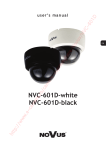
Digital Video Security Systems formerly DPV74TLUX D3200/D3300 Series 960H IRVideo Vandal Surveillance Dome Camera Recorder Digital 4/8/16/32 960H Real-time View & Record CMS Mobile Apps HDMI Instruction Manual English Version 2.0 Instruction Manual English Version 1.0 www.digimerge.com www.flir.com/security www.digimerge.com Copyright © 2013 Digimerge Technologies Inc., a FLIR Company www.flir.com/security Digital Video Security Systems -2- Digital Video Security Systems -3- Digital Video Security Systems Contents Contents............................................................................... 3 General Features.................................................................. 4 Precautions........................................................................... 5 Safety precautions...................................................................................... 6 Please handle this camera carefully........................................................... 6 Safety Instructions............................................................... 6 Package Contents................................................................. 7 Surface Mount............................................................................................. 8 Installation............................................................................ 8 Flush Mount................................................................................................ 9 Junction Box Installation.......................................................................... 10 Adjusting the Camera............................................................................... 11 Connection......................................................................... 12 How to Set Up the Camera Menu..................................... 13 Menu Tree................................................................................................. 14 Menu Tree (Continued)............................................................................. 15 Menu Tree................................................................................................. 16 Default Settings........................................................................................ 17 Lens............................................................................................................ 19 Exposure.................................................................................................... 19 White Balance........................................................................................... 22 Day&Night................................................................................................. 24 3DNR (3D-Digital Noise Reduction)......................................................... 25 Special........................................................................................................ 26 Adjust......................................................................................................... 32 Reset.......................................................................................................... 33 Exit............................................................................................................. 33 Dimensions................................................................................................ 34 Specifications..................................................................... 34 Troubleshooting................................................................. 35 -3- Digital Video Security Systems General Features •1/3” Sony EX-View™ II 960H •UL standard 60065 Approved •Built-in video balun (UTP) •Up-the-coax (UTC) OSD via UTC controller* •Polaris Vision2 low light viewing •Smart-IR Night Vision (100ft/31m) with Adjustable LED Power Level •3.5-16mm Auto Iris D/N Varifocal Lens •True Day Night with ICR (TDN) •IP67 Weatherproof rated and Vandalproof •Advanced 3D Digital Noise Reduction (3D-DNR) •ArcticPro technology for harsh climates with Cold Starter (minimum operating temperature -40°F) •Precise zoom / focus adjustment with included adjustment tool •Privacy Masking / Motion Detection •24V AC Operation •Service Monitor Output •Full 90° tilting angle, surface and flush mountable * UTC controller accessory sold separately -4- Digital Video Security Systems Precautions Do not install the camera in extreme temperature conditions. Do not install or use the camera in an environment where the humidity is high. Only use the camera in environments between -40°C and +50°C. Do not touch the front lens of the camera. This is one of the most important parts of the camera. Be careful not to leave fingerprints on the lens cover. Do not expose the camera to rain or spill liquids on it. If it gets wet, wipe dry immediately. Liquids can contain minerals that corrode the electronic components. Do not install the camera under unstable lighting conditions. Severe lighting change or flicker can cause the camera to work improperly. Never keep the camera pointed directly at strong light. Do not drop the camera or subject it to physical shocks. It can cause malfunctions to occur. Do not expose the camera to radioactivity. If exposed to radioactivity the CCD will fail. -5- NOTE •If the camera is exposed to spotlight or strong lighting, smear or blooming may occur. •Please check that the power satisfies the requirements listed in the Specifications before connecting the camera. Digital Video Security Systems Safety Instructions Safety precautions •This camera should be installed by qualified personnel only. •There are no user serviceable parts inside. Do not disassemble the camera. •Use an appropriate low voltage power cable to prevent fire or electrical shock. •Please ensure that your installation area can support the weight of the camera. Please handle this camera carefully •Do not use a strong or abrasive detergent when cleaning the camera. •Do not expose the camera to direct sun. •Do not install the camera in high humidity environments. •Do not install the camera near cooling or heating devices. -6- Digital Video Security Systems Package Contents Camera (x1) Tapping Screw 4x25 (x4) Machine Screw M4x10 (x3) Allen Key (x1) Camera Termination Cable (x1) Test Video Cable (x1) Accessories •MNTV74J Junction box mount. Zoom / Focus Adjustment Tool (x1) Flush Mounting Template (x1) •MNTV74W Wall mount. •MNTV74C Ceiling Mount. •ACCUTC1 UTC Controller. Instruction Manual (x1) Surface Mounting Template (x1) -7- Contact your distributor for details. Digital Video Security Systems Installation Do not remove the protective film on the dome cover until the installation is completed. Surface Mount 1. Use the included surface mounting template to drill holes for the cable and mounting screws. 2. Run the extension cables through the surface and connect the camera termination cable to the extension cable. 3. Run the camera termination cable through the camera base. NOTE If running the cable through the side conduit (side conduit is 1/4” diameter), perform the following instead of steps 2 and 3: a. Remove the rubber gasket under the camera base. b. Unscrew the side conduit cap using a flat-head screwdriver or coin. c. Run the camera cable through the side conduit hole. Connect the camera termination cable to the camera cable outside the camera housing. d. Replace the rubber gasket. 4. Attach the camera base to the surface using the tapping screw 4x25 (4x). Ensure the rubber gasket is firmly attached to the camera base to ensure the weatherproof rating of the camera. Camera Termination Cable Camera Cable Rubber Gasket Camera Base Tapping Screw 4x25 (4x) Camera Module Machine Screw M4x10 (3x) Dome Cover 5. Use the included allen key to loosen the dome cover screws (3x) and then remove the dome cover from the camera module. 6. Connect the camera termination cable to the camera cable. Push the cable connection point through the camera base into the surface. 7. Attach the camera module to the camera base using the machine screws M4x10 (3x). Go to “Adjusting the Camera” on page 11. -8- Digital Video Security Systems Flush Mount 1. Cut a hole in the ceiling using the inside line of the included flush mounting template. Drill holes as marked on the template. Cut along inside line Drill mounting holes Flush Mounting Template 2. Run the extension cables through the ceiling and connect the camera termination cable to the extension cable. 3. Connect the camera cable to the camera termination cable inside the ceiling. 4. Use the included allen key to loosen the dome cover screws (3x) and then remove the dome cover. 5. Attach the camera module to the ceiling using the tapping screw 4x25 (3x). Camera Termination Cable Camera Cable Camera Module Tapping Screw 4x25 (3x) Dome Cover Go to “Adjusting the Camera” on page 11. -9- Digital Video Security Systems Junction Box Installation The camera is compatible with 2S and Two Gang junction boxes. To install the camera to a junction box: 1. Connect the camera termination cable to the extension cables inside the junction box. 2. Run the camera termination cable through the camera base. 3. Attach the camera base to the junction box according to the junction box type used (see below). 2S Junction Box (requires 2x screws) Two Gang Junction Box (requires 4x screws) NOTE: Screws are not provided for junction box installation. Ensure the rubber gasket is firmly attached to the camera base to ensure the weatherproof rating of the camera. Camera Termination Cable Camera Cable Rubber Gasket 4. Connect the camera cable to the termination cable and push the cable connection point through the camera base into the junction box. 5. Use the included allen key to loosen the dome cover screws (3x) and then remove the dome cover from the camera module. 6. Attach the camera module to the camera base using the machine screws M4x10 (3x). Camera Base Junction Box Screw (Not included; 2x or 4x) Camera Module Machine Screw M4x10 (3x) Dome Cover Go to “Adjusting the Camera” on page 11. - 10 - Digital Video Security Systems Adjusting the Camera 1. With the dome cover removed, you can adjust the camera viewing angle, zoom/focus, LED level, and OSD. • (Optional) Connect the included video test cable to the Video Test connector to output the video to a BNC test monitor. • To adjust the viewing angle of the camera, tilt the lens up and down (up to 90°) or hold the sides of the lens and twist the camera around up to 175° in either direction (up to 350°). 175° 90° 175° NOTE: There is a stopper to prevent the camera from twisting beyond the limits of the internal cables. Do not try to twist the camera past the stopper. • To adjust the zoom / focus, loosen the middle Lock screw with a philipshead screwdriver. Then turn the Zoom and Focus screws using the included zoom/focus adjustment tool or with a small philipshead screwdriver. Make sure to re-tighten the Lock screw when finished adjusting the lens. • To adjust the power output to the IR LEDs, use a small philipshead screwdriver to turn the LED Level screw left to decrease the output or right to increase the output. It is recommended to fine tune the IR level during low light conditions to determine the best setting. NOTE: By default, the IR LEDs are set for maximum output. For short-range installation environments, it is recommended to turn down the LED level. • For details on adjusting the OSD menu, see “How to Set Up the Camera Menu” on page 13. Test Monitor OSD Output Joystick LED Level NOTE: OSD menu can also be controlled using a UTP controller (Pelco C protocol; accessory model number: ACCUTC1). 2. Replace the dome cover and tighten the dome cover screws (3x). 3. Remove the protective film from the dome cover. - 11 - Digital Video Security Systems Connection This camera supports 24V AC power only. a. b. c. a.Power: Connect the camera to a 24V AC power source. b.BNC Video: Connect the camera to the video cable. You can also control the camera OSD over the video cable using a UTC controller (Pelco C protocol). OR c.UTP Video: Connect the camera to a video balun using one pair from a UTP cable (for example, Cat 5). Make sure to match the correct polarity as marked on the balun. - 12 - Digital Video Security Systems How to Set Up the Camera Menu Use the camera menu to configure image quality and other camera settings. To access the camera menu: 1. Use the included allen key to loosen the dome cover screws (3x) and remove the dome cover from the camera. OR Connect a UTC controller (Pelco C protocol) to the video cable and continue running the cable to the DVR or monitor. 2. Press and hold the Set Up (middle) button to open the OSD menu. •Press Up/Down to move the menu cursor up and down and select menu items. •Press Left/Right to move the menu cursor left and right and adjust the selected menu item. •Press the Set Up button to open sub-menus or confirm selections. 3. When you are finished making changes to the menu, select Exit and press Set Up. OSD Joystick NOTE •Arrow icon ( ) indicates sub-menu is available. •You must Exit the OSD menu to save menu changes. Otherwise, changes will not be saved if there is a power failure. •To save changes, return to the main OSD menu, select EXIT, and press the Set Up button. Or, in sub-menus, select SAVE&END and press Set Up to save changes and exit the OSD menu. - 13 - Digital Video Security Systems Menu Tree ΄Ͷ΅͑Ά͑;ͶͿΆ ͽͶͿ΄ ;ͶͿΆ ͵ͶͷͲΆͽ΅͑΄Ͷ΅ ͵ʹ ΄Ά΅΅Ͷ Ͳʹ ͳͺ΅ͿͶ΄΄ ͑ ͑ ͡ί͑͢͡͡ͽΖΧΖΝ͑΄ΖΝΖΔΥΒΓΝΖ ͺͿ͵ ;͵Ͷ Ά΅͵ Ͷ΅ Ͷ΅ΆͿ ΄Ͳ·Ͷ͗ͶͿ͵ Ωͣ͑͝Ωͥ͑͝Ωͧ͑͝Ωͩ͑͝Ω͑͢͡͝Ωͣ͑͢͝Ωͥ͑͢͝Ωͧ͑͢͝Ωͣͥ͑͝Ωͤͣ͑͝Ωͧͥ͑͝Ωͣͩ͑͢͝Ωͣͦͧ͑͝ͲΆ΅͑ͧ͑͢͝͠͡͝ͷͽͼ͑ͣͦ͑ͦ͢͢͝͠͡͝͠͡͡͝ ͑ͣ͑ͦ͑͑ͣ͑ͦ͑͢͢͢͢͢͢͢͢͢͢͠͡͡͡͝͠͡͡͡͝͠͡͡͡͝͠͡͡͡͡͝͠͡͡͡͡͝͠͡͡͡͡͠͡͡͡͡͡ ͷͷ ͽΈ͑ ;ͺ͵͵ͽͶ ͺ͑ ͲΆ΅ ΄ͶͿ΄Ͷ͞Ά ΄ͶͿ΄Ͷ͞Ά͙Ωͣ͑ί͑Ωͣͦͧ͑ͽΖΧΖΝ͑΄ΖΝΖΔΥΒΓΝΖ͚ Ͷ΅ Ͷ΅ΆͿ ΄Ͳ·Ͷ͗ͶͿ͵ ͷͷ ͷͷ ͽΈ ;ͺ͵͵ͽͶ ͺ ΄ͺ΅ͺͿ ΄ͺͶ ͲͲͺͿ ·ͲͽΆͶ ͳͽʹ ͶΉ΄ΆͶ ͲͶͲ ͵ͶͷͲΆͽ΅ ͳͽʹ Ͷ΅ ΄Ͳ·Ͷ͗ͶͿ͵ ͑͡ί͑ͩ͑ͽΖΧΖΝ͑΄ΖΝΖΔΥΒΓΝΖ Ͳͽͽ͑͵ͲΊ Ϳͺ΅͑ͿͽΊ Ͷ΅ΆͿ ͲͺͿ ;͵Ͷ ΄ͳͽʹ ͵ͶͷͲΆͽ΅ Ͷ΅ ΄Ͳ·Ͷ͗ͶͿ͵ Ͷ΅ΆͿ ͷͷ ͺͿ͵ ͽΈ͑ͽͶ·Ͷͽ ͺ͑ͽͶ·Ͷͽ Ͷ΅ΆͿ ͵͞Έ͵ Ά΅͵ ͽΈ͑ͽͶ·Ͷͽ ͺ͑ͽͶ·Ͷͽ Ͷ΅ΆͿ Ͷ΅ΆͿ ͑͡ί͑ͦ͑͢ͽΖΧΖΝ͑΄ΖΝΖΔΥΒΓΝΖ ͑͡ί͑ͦ͑͢ͽΖΧΖΝ͑΄ΖΝΖΔΥΒΓΝΖ Ͷ΅ ΄Ͳ·Ͷ͗ͶͿ͵ ͑͡ί͑ͦ͑͢ͽΖΧΖΝ͑΄ΖΝΖΔΥΒΓΝΖ ͑͡ί͑ͦ͑͢ͽΖΧΖΝ͑΄ΖΝΖΔΥΒΓΝΖ Ͷ΅ ΄Ͳ·Ͷ͗ͶͿ͵ Ͷ΅ ΄Ͳ·Ͷ͗ͶͿ͵ Ͳ΅Έ ͲΈͳ ͲΈʹͯ͞΄Ͷ΅ Έͺ΅Ͷ͑ͳͲͽ ;ͲͿΆͲͽ ͳͽΆͶ Ͷ͵ Ͷ΅ΆͿ ͑͑͡ί͑͢͡͡ͽΖΧΖΝ͑΄ΖΝΖΔΥΒΓΝΖ ͑͑͡ί͑͢͡͡ͽΖΧΖΝ͑΄ΖΝΖΔΥΒΓΝΖ Ͷ΅ ΄Ͳ·Ͷ͗ͶͿ͵ ʹͽ ͳΆ΄΅ Ϳ͠ͷͷ ·ͲͽΆͶ ͺ͑΄;Ͳ΅ ͳ͠Έ ͲͶͲ Ϳ ͺ͑͵Έ͵ Ͷ΅ΆͿ ͵ͲΊ͠Ϳͺ΅ Ͷ΅ΆͿ ͲΆ΅ ͵ͶͽͲΊ ͵͑ͯ͑͞͞Ϳ͙͑Ͳʹ͚ Ϳ͑ͯ͑͞͞͵͙͑Ͳʹ͚ Ͷ΅ΆͿ ͶΉ΅ ΄΅Ͳ΅͑͵ͶͽͲΊ ͶͿ͵͑͵ͶͽͲΊ Ͷ΅ΆͿ ͷͷ Ͷ΅͑ ΄Ͳ·Ͷ͗ͶͿ͵ ͑͡ίͦ͑͢ͽΖΧΖΝ͑΄ΖΝΖΔΥΒΓΝΖ ͑͡ί͑ͣͦͦ͑ͽΖΧΖΝ͑΄ΖΝΖΔΥΒΓΝΖ ͑͡ί͑ͣͦͦ͑ͽΖΧΖΝ͑΄ΖΝΖΔΥΒΓΝΖ Ͷ΅͑ ΄Ͳ·Ͷ͗ͶͿ͵ ͑͡ίͦ͑͢ͽΖΧΖΝ͑΄ΖΝΖΔΥΒΓΝΖ ͑͡ίͦ͑͢ͽΖΧΖΝ͑΄ΖΝΖΔΥΒΓΝΖ Ͷ΅ ΄Ͳ·Ͷ͗ͶͿ͵ - 14 - ͑͡ί͑͑͢͡͡ͽΖΧΖΝ͑΄ΖΝΖΔΥΒΓΝΖ ΄ͺ΅ͺͿ ΄ͺͶ Ͷ΅͠ͲͲͺͿ ͷͷ͑͑͢͠ίͦ͑͢ͽΖΧΖΝ͑΄ΖΝΖΔΥΒΓΝΖ Ͷ΅ ΄Ͳ·Ͷ͗ͶͿ͵ Digital Video Security Systems Menu Tree (Continued) ͷͷ ͤ͵Ϳ ͽͶ·Ͷͽ Ϳ ʹͲ;͑΅ͺ΅ͽͶ Ͷ΅ΆͿ Ϳ ͷͷ ͷͶͶͶ ;ͺ ͑͢ί͑ͣ͑͡͡ͽΖΧΖΝ͑΄ΖΝΖΔΥΒΓΝΖ Ͷ΅ ΄Ͳ·Ͷ͗ͶͿ͵ Ϳ͠ͷͷ ;ͺ ·͞ͷͽͺ ΅Ͳ΅Ͷ ͷͷ Ϳ ͵͞; ͲͿͶ ͲͿ ΅ͺͽ΅ Ͷ΅ΆͿ ͷͷ ͷͷ ͵͞ͶͷͷͶʹ΅ ΄;Ͳ΅͑͵; ͲͿͶ ΄ͺ΅ͺͿ ΄ͶͿ΄ͺ΅ͺ·ͺ΅Ί ΅ͺ;Ͷ Ϳ Ͷ΅ΆͿ ͵ͺ΄ ͿͶ͑͟ͺ;ͲͶ Ͷ΅ΆͿ ;΅ͺͿ Ω͑͢ί͑Ωͤͣ͑΄ΖΝΖΔΥΒΓΝΖ ͑͢͞͡͡ί͑͑͢͡͡΄ΖΝΖΔΥΒΓΝΖ ͑͢͞͡͡ί͑͑͢͡͡΄ΖΝΖΔΥΒΓΝΖ Ͷ΅ ΄Ͳ·Ͷ͗ͶͿ͵ Ϳ ΄ͶʹͺͲͽ Ωͣ͑ί͑Ωͦ͑΄ΖΝΖΔΥΒΓΝΖ ͽͶͷ΅͠ͺ΅͠Ά͠͵ΈͿ ͑͡ί͑͑͢͡͡ͽΖΧΖΝ͑΄ΖΝΖΔΥΒΓΝΖ ͑͡ί͑ͦ͑͢ͽΖΧΖΝ͑΄ΖΝΖΔΥΒΓΝΖ Ͷ΅ ΄Ͳ·Ͷ͗ͶͿ͵ Ϳ͠ͷͷ Ϳ͠ͷͷ Ͷ΅ ΄Ͳ·Ͷ͗ͶͿ͵ ͲͶͲ͑ ͑͢ί͑ͥ͑΄ΖΝΖΔΥΒΓΝΖ ΄ͺ΅ͺͿ Ϳ ΄ͺͶ ͲͶͲ͑͵ͺ΄ͽͲΊ Ͷ΅͠ͲͲͺͿ ͷͷ ͑͡ί͑͑͢͡͡ͽΖΧΖΝ͑΄ΖΝΖΔΥΒΓΝΖ ·ͲͽΆͶ ;΅ͺͿ͑·ͺͶΈ Ϳ͠ͷͷ Ͷ΅ Ͷ΅ΆͿ ΄Ͳ·Ͷ͗ͶͿ͵ ͷͷ ͲͶͲ ͺ·ͲʹΊ ͵ͶͷͶʹ΅ Ϳ ͑͢ί͑ͩ͑΄ΖΝΖΔΥΒΓΝΖ ΅͑ͽͶͷ΅ ΅͑ͺ΅ ͳ΅;͑ͽͶͷ΅ Ϳ ͲͶͲ͑͵ͺ΄ͽͲΊ ͳ΅;͑ͺ΅ ΄ͺ΅ͺͿ Ͷ΅͠ͲͲͺͿ ͷͷ ͑͢ί͑ͦ͑͢΄ΖΝΖΔΥΒΓΝΖ ʹͽ ͑͡ί͑ͤ͑΄ΖΝΖΔΥΒΓΝΖ ΅ͲͿ΄Ͳ Ͷ΅ Ͷ΅ΆͿ ΄Ͳ·Ͷ͗ͶͿ͵ ͷͷ ΄ͶͿ΄ͶΆ ͵ͺͷͷ ΅Ͷ΄ͽ͵ ΄΅Ͳ΅ Ωͥ͑ί͑Ωͣͩ͑͑͢ͽΖΧΖΝ͑΄ΖΝΖΔΥΒΓΝ ͑͡ί͑ͤ͑ͽΖΧΖΝ͑΄ΖΝΖΔΥΒΓΝΖ ͑͡ί͑ͥ͑ͽΖΧΖΝ͑΄ΖΝΖΔΥΒΓΝΖ Ͷ΅ΆͿ Ͷ΅ ΄Ͳ·Ͷ͗ͶͿ͵ ͷͷ ;ͲͿΆͲͽ ͵Ͷͷ ͲΆ΅ Ͷ΅ΆͿ ͑͡ί͑ͤ͑͢ͽΖΧΖΝ͑΄ΖΝΖΔΥΒΓΝΖ ͑͡ί͑͑͢͡ͽΖΧΖΝ͑΄ΖΝΖΔΥΒΓΝΖ ͑͡ί͑͑͢͡ͽΖΧΖΝ͑΄ΖΝΖΔΥΒΓΝΖ Ά΄Ͷ͑ͦ͑͟͝͡͡ί͑͑͢͟͡͡ͽΖΧΖΝ͑΄ΖΝΖΔΥΒΓΝΖ Ͷ΅ Ͷ΅ΆͿ ΄Ͳ·Ͷ͗ͶͿ͵ ͵Ͷ΅Ͷʹ΅͑ͽͶ·Ͷ ͑͡ί͑ͦ͑ͽΖΧΖΝ͑΄ΖΝΖΔΥΒΓΝΖ Ͷ΅ Ͷ΅ΆͿ ΄Ͳ·Ͷ͗ͶͿ͵ ͽͶ·Ͷͽ ʹͽ͑ͲͺͿ Ͷ͵Ͷ͑ͲͺͿ Ͳ;;Ͳ Ͷ΅ ͶͿ͵ - 15 - Digital Video Security Systems Menu Tree ΄ͲͿͶ΄΄ ͑͡ί͑ͤ͑͢ͽΖΧΖΝ͑΄ΖΝΖΔΥΒΓΝΖ Ͳ;;Ͳ ͽͶ·Ͷͽ ͳͽΆͶ͑ͲͺͿ͑ ͽʹ͵ Ͷ͵͑ͲͺͿ͑ Ͷ΅ΆͿ Ͳ͵ͻΆ΄΅ ;Ϳͺ΅ ʹ΅ ͽͶ·Ͷͽ ͳͽΆͶ͑ͲͺͿ͑ Ͷ͵͑ͲͺͿ͑ Ͷ΅ΆͿ Ά΄Ͷ Ͳ;;Ͳ ͽͶ·Ͷͽ ͳͽΆͶ͑ͲͺͿ͑ Ͷ͵͑ͲͺͿ͑ Ͷ΅ΆͿ Ͷ΅ΆͿ ͷͲʹ΅Ί Ͷ΄Ͷ΅ Ͷ΅ΆͿ Ͷ΅ ΄Ͳ·Ͷ͗ͶͿ͵ Ͷ΄Ͷ΅ Ͷ΅ ΄Ͳ·Ͷ͗ͶͿ͵ ͶΉͺ΅ - 16 - Ά΄Ͷ͑ͦ͑͟͝͡͡ί͑͑͢͟͡͡ͽΖΧΖΝ͑΄ΖΝΖΔΥΒΓΝΖ ͑͡ί͑ͧͤ͑ͽΖΧΖΝ͑΄ΖΝΖΔΥΒΓΝΖ ͑͡ί͑ͣͦͦ͑ͽΖΧΖΝ͑΄ΖΝΖΔΥΒΓΝΖ ͑͡ί͑ͣͦͦ͑ͽΖΧΖΝ͑΄ΖΝΖΔΥΒΓΝΖ Ͷ΅ ΄Ͳ·Ͷ͗ͶͿ͵ ͑͡ί͑ͧͤ͑ͽΖΧΖΝ͑΄ΖΝΖΔΥΒΓΝΖ ͑͡ί͑ͣͦͦ͑ͽΖΧΖΝ͑΄ΖΝΖΔΥΒΓΝΖ ͑͡ί͑ͣͦͦ͑ͽΖΧΖΝ͑΄ΖΝΖΔΥΒΓΝΖ Ͷ΅ ΄Ͳ·Ͷ͗ͶͿ͵ Ά΄Ͷ͑ͦ͑͟͝͡͡ί͑͑͢͟͡͡ͽΖΧΖΝ͑΄ΖΝΖΔΥΒΓΝΖ ͑͡ί͑ͧͤ͑ͽΖΧΖΝ͑΄ΖΝΖΔΥΒΓΝΖ ͑͡ί͑ͣͦͦ͑ͽΖΧΖΝ͑΄ΖΝΖΔΥΒΓΝΖ ͑͡ί͑ͣͦͦ͑ͽΖΧΖΝ͑΄ΖΝΖΔΥΒΓΝΖ Ͷ΅ ΄Ͳ·Ͷ͗ͶͿ͵ Digital Video Security Systems Default Settings Setting Default Value Lens -> DC -> Brightness 50 Lens -> DC -> Mode Indoor Exposure -> Shutter 1/60 Exposure -> Brightness 50 Exposure -> AGC Middle Exposure -> Sense-Up X32 Exposure -> BLC Off Exposure -> BLC -> BLC -> Value Middle Exposure -> BLC -> HSBLC -> Gain 8 Exposure -> BLC -> HSBLC -> Mode All Day Exposure -> D-WDR Off Exposure -> Indoor -> Low Level 4 Exposure -> Indoor -> High Level 11 Exposure -> Outdoor -> Low Level 0 Exposure -> Outdoor -> High Level 0 White Bal ATW White Bal -> Manual -> Blue 28 White Bal -> Manual -> Red 16 Day&Night EXT Day&Night -> EXT -> Start Delay 5 Day&Night -> EXT -> End Delay 2 Day&Night -> B/W -> Burst Off Day&Night -> B/W -> IR Smart On Day&Night -> B/W -> IR Smart -> Value 50 Day&Night -> B/W -> IR Smart -> IR DWDR 2 Day&Night -> Auto -> Delay 5 Day&Night -> Auto -> D --> N (AGC) 60 Day&Night -> Auto -> N --> D (AGC) 20 3DNR ON 3DNR -> Level 200 Special -> Cam Title Off Special -> D-Effect -> Mirror Off Special -> D-Effect -> D-Zoom Off Special -> D-Effect -> D-Zoom -> Range x 2.0 Special -> D-Effect -> D-Zoom -> Pan 0 Special -> D-Effect -> D-Zoom -> Tilt 0 - 17 - Digital Video Security Systems Setting Default Value Special -> D-Effect -> Smart DZoom Off Special -> D-Effect -> Smart DZoom -> Range x 2.0 Special -> D-Effect -> Sensitivity 80 Special -> D-Effect -> Time 3 Special -> D-Effect -> DIS Off Special -> D-Effect -> Neg. Image Off Special -> Motion Off Special -> Motion -> Area 1 Special -> Motion -> Area Display On Special -> Motion -> Value 80 Special -> Motion -> Motion View Off Special -> Privacy Off Special -> Privacy -> Area 1 Special -> Privacy -> Area Display On Special -> Privacy -> Color 10 Special -> Privacy ->Transpar 3 Special -> Defect -> Sensup X32 Special -> Defect -> Diff 2 Special -> Defect -> Threshold 1 Special -> Defog Off Special -> Defog -> Manual -> Level 10 Special -> Defog -> Manual -> Color Gain 3 Special -> Defog -> Manual -> Edge Gain 3 Special -> Defog -> Auto -> Detect Level 3 Adjust -> Sharpness 25 Adjust -> Monitor LCD Adjust -> Monitor -> LCD -> Gamma 0.55 Adjust -> Monitor -> LCD -> Level 20 Adjust -> Monitor -> LCD -> Blue Gain 100 Adjust -> Monitor -> LCD -> Red Gain 100 Adjust -> Monitor -> User -> Gamma 0.55 Adjust -> Monitor -> User -> Level 20 Adjust -> Monitor -> User -> Blue Gain 130 Adjust -> Monitor -> User -> Red Gain 130 Adjust -> Monitor -> CRT -> Level 20 Adjust -> Monitor -> CRT -> Blue Gain 110 Adjust -> Monitor -> CRT -> Red Gain 110 - 18 - Digital Video Security Systems Lens The Lens submenu is used to adjust the brightness of the camera. 1. Press Up/Down to select LENS and then press Set Up. SETUP LENS EXPOSURE WHITE BAL DAY&NIGHT 3DNR SPECIAL ADJUST RESET EXIT DCAUTO ATW COLOR ON 2. Press Up/Down to select BRIGHTNESS and then Left/Right to adjust the brightness between 1~100. 3. Press Up/Down to select MODE and then Left/Right to select INDOOR or OUTDOOR depending on the installation environment. DC LENS BRIGHTNESS MODE RETURN IIIIIIIIII|IIIIIIIIII 50 INDOOR RET Exposure 1. Press Up/Down to select EXPOSURE and then press Set Up. SETUP LENS EXPOSURE WHITE BAL DAY&NIGHT 3DNR SPECIAL ADJUST RESET EXIT DC ATW COLOR ON - 19 - Digital Video Security Systems 2. Configure the following: •Shutter: Press Left/Right to select AUTO shutter speed, adjust the shutter speed between 1/60~1/100,000 or 2x~x256, or select FLK mode. EXPOSURE SHUTTER AGC SENSE-UP BLC D-WDR RETURN AUTO MID AUTO OFF OFF RET •AGC (Auto Gain Control): Press Left/Right to adjust AGC. Increasing the AGC level may increase the amount of noise in the image. »» Off: AGC disabled. »» Low: 28dB gain applied. »» Mid: 32dB gain applied. »» High: 36dB gain applied. •Sense-Up: Press Left/Right to enable/disable Digital Slow Shutter (DSS) function. Slow Shutter uses a combination of gain and a reduction in shutter speed to compensate for decreased light levels. »» Off: DSS disabled. »» Auto: Enable DSS. Press Set Up and then press Left/Right to adjust the maximum shutter speed adjustment between 2x~256x. SENSE-UP SENSE-UP RETURN x32 RET NOTE •Sense-Up is disabled if Shutter is not set to AUTO or 1/60. •To limit ghosting effect, it is recommended to select a Sense-Up between 2x and 32x. - 20 - Digital Video Security Systems •BLC (Back Light Compensation): The camera uses auto exposure control to automatically tone down highlighted areas of the image. »» Off: Disable BLC. »» BLC: Enable BLC in a user defined area. In this mode, the camera will decrease the brightness in selected areas with highlights. Press Set Up to configure the BLC area and level: BLC VALUE AREA DEFAULT RETURN MIDDLE RET »» Value: Set the BLC level: Low, Medium, or High. »» Position: Set the area where BLC will be applied. Press Set Up and press Left/Right/Up/Down to adjust the position of the area. Press Set Up to confirm the area and then press Left/Right/Up/Down to adjust the size of the area. Press Set Up to confirm the size and then press Set Up again to return to the BLC sub-menu. »» Default: Press Set Up to return the BLC level and area to the default settings. »» HSBLC (Highlight Suppression Back Light Compensation): HSBLC actively blocks highlighted areas in the image. For example, when there is a car headlight turned on at the entrance of a gas station, the numbers of the car plate may be recognized by blocking the light from the car headlight. Press Set Up to configure HSBLC settings: HSBLC GAIN MODE DEFAULT RETURN IIIIIIIIII|IIIIIIIIII 8 ALL DAY RET Normal HSBLC - 21 - Digital Video Security Systems »» Gain: Press Left/Right to adjust the gain tolerance between 1~8. The higher this value is, the brighter areas of the image will need to be for the camera to block them. »» Mode: Press Left/Right to select ALL DAY for HSBLC to be enabled in both day and night mode or NIGHT ONLY for HSBLC to be enabled during night mode only. »» Default: Press Set Up to return to default HSBLC settings. •D-WDR (Digital Wide Dynamic Range): D-WDR automatically adjusts the light level in parts of the image to overcome strong backlight conditions. »» Off: Disable D-WDR. »» Indoor: Compensates for typical indoor lighting conditions. Press Set Up to adjust the Low Level and High Level for D-WDR. »» Outdoor: Compensates for typical outdoor lighting conditions. Press Set Up to adjust the Low Level and High Level for D-WDR. D-WDR OFF D-WDR ON White Balance Use the White Balance function to adjust the color of the image. 1. Press Up/Down to select White Bal. SETUP LENS EXPOSURE WHITE BAL DAY&NIGHT 3DNR SPECIAL ADJUST RESET EXIT DC ATW COLOR ON - 22 - Digital Video Security Systems 2. Press Left/Right to select the best White Balance mode for your installation: •ATW (Auto-Trace White Balance): Use this mode when the color temperature is between 1,800K to 10,500K. •AWB (Auto White Balance): Because ATW may not work properly in certain conditions, it is recommended to use this mode if one of the following conditions is present in your installation: »» When there is a very high color temperature in the image (above 10,500K; for example, clear sky or sunset). »» It is very dark. »» If the camera is pointed directly at fluorescent lighting or if there is a drastic lighting change, the operation of white balance may become unstable. •AWC-->SET: Place a white card in front of the camera lens and then press the Set Up button to set the white balance setting. If the lighting condition changes, you may need to re-adjust the white balance. •Manual: Use the manual option to manually adjust the blue and red levels. Press Set Up, then press Left/Right to adjust the Blue and Red levels. MANUAL WB BLUE RED RETURN IIIIIIIIII|IIIIIIIIII IIIIIIII|IIIIIIIIIIII - 23 - 31 20 RET Digital Video Security Systems Day&Night The Day&Night sub-menu allows you to configure day and night modes. 1. Press Up/Down to select Day&Night. SETUP LENS EXPOSURE WHITE BAL DAY&NIGHT 3DNR SPECIAL ADJUST RESET EXIT DC ATW COLOR ON 2. Press Left/Right to select one of the following modes: • Color: Image will always be in color (day mode). •B/W: Image will always be in black & white (night mode). Press Set Up to enter the B/W sub-menu. DAY&NIGHT B/W BURST IR SMART RETURN OFF ON RET »» Burst: Press Left/Right to select Off to eliminate the burst signal or On to allow the burst signal. »» IR Smart: Press Left/Right to select On to enable Smart IR compensation or Off to disable. Smart IR will prevent the image from becoming overexposed if objects come too close to the camera at night. If set to On, press Set Up to configure the following: »» Value: Press Left/Right to adjust the amount the camera will compensate for IR saturation. »» Area: Press Set Up to adjust the area where the camera will apply Smart IR compensation. »» IR DWDR: Press Left/Right to increase the level of D-WDR that will be applied for Smart IR. This will brighten areas outside of the Smart IR area. - 24 - Digital Video Security Systems NOTE •Settings changed in the IR Smart menu are saved if you change Day & Night to EXT or AUTO. •EXT (Recommended): Camera uses the CdS sensor to detect lighting conditions and automatically select between day and night mode. Press Set Up to set the Start Delay and End Delay. •Auto: Camera uses the internal sensor to detect lighting conditions and select between day and night mode. Press Set Up to configure the following parameters for auto day/night mode: »» Delay: Press Left/Right to select the delay time before the camera will switch between day and night modes. »» D->N(AGC): Select the brightness value when the camera changes from day mode to night mode. »» N->D(AGC): Select the brightness value when the camera changes from night mode to day mode. DAY&NIGHT AUTO DELAY D → N(AGC) N → D(AGC) RETURN IIII|IIIIIIIIIIIIIIII IIIIIIII|IIIIIIIIIIII IIIIIIIIII|IIIIIIIIII 5 60 20 RET 3DNR (3D-Digital Noise Reduction) 3DNR allows you to configure 3D-Digital Noise Reduction (3D-DNR). 3D-DNR reduces noise in the image during night mode. 1. Press Up/Down to select 3DNR. SETUP LENS EXPOSURE WHITE BAL DAY&NIGHT 3DNR SPECIAL ADJUST RESET EXIT DC ATW COLOR ON - 25 - Digital Video Security Systems 2. Press Left/Right to select ON to enable 3D-DNR or select OFF to disable. If you select ON, press Set Up to set the compensation level for 3D-DNR between 0~200. 3DNR LEVEL RETURN IIIIIIIIII|IIIIIIIIII 200 RET NOTE As the level is increased, the effectiveness of the noise reduction will increase, but ghosting or a softening of the image may occur. Special The Special menu contains miscellaneous camera functions. 1. Press Up/Down to select Special and press the Set Up button. SETUP LENS EXPOSURE WHITE BAL DAY&NIGHT 3DNR SPECIAL ADJUST RESET EXIT DC ATW COLOR ON The Special menu contains the following functions: SPECIAL CAM TITLE D-EFFECT MOTION PRIVACY DEFECT DEFOG RETURN OFF OFF OFF OFF RET - 26 - Digital Video Security Systems •CAM TITLE: Press Left/Right to select OFF to disable the camera title display on the OSD. Or, select ON to enable camera title display and press Set Up to configure the camera title. To configure the camera title, do the following: CAM TITLE 0 1 2 3 4 5 6 7 8 9 ABCDEFGHIJK LMNOPQRSTUV W X Y Z ▶ → ← ↑↓ ( ) α - _ ■ / = & : , . ←→ CLR POS END CAMERA 001 _______________ a.Press Up/Down/Left/Right to control the menu cursor. b.Press Set Up to enter the selected character. c.Use the <- and -> controls to edit the previous character or next character in the title. d.Select CLR and press Set Up to erase all characters. e.Select POS and press Set Up to configure the position of the camera title. Then, press Left/Right/Up/Down to set the position. Press Set Up again when finished. f. Select END and press Set Up to save the camera title. NOTE If you want to enter a space or erase a letter, move the cursor on the empty space in front of the number 0 and press Set Up. •D-Effect: Press Set Up to open the D-Effect sub-menu. This sub-menu allows you to apply the following digital effects to the image. D-EFFECT FREEZE MIRROR D-ZOOM SMART DZOOM DIS NEG.IMAGE RETURN - 27 - OFF OFF --OFF --OFF RET Digital Video Security Systems »» Freeze: Press Left/Right to select ON to freeze the image in place. Select OFF to unfreeze the image. »» Mirror: Press Left/Right to flip the image in one of the following directions: OFF MIRROR ROTATE V-FLIP »» D-Zoom: Press Left/Right to select ON to enable digital zoom or OFF to disable. Press Set Up to configure the following: D-ZOOM RANGE PAN TILT RETURN IIIIIIIIII|IIIIIIIIII IIIIIIIIII|IIIIIIIIII x2.0 0 0 RET »» Range: Press Left/Right to apply 1x~32x digital zoom to the image. »» PAN: Press Left/Right to move the zoom area left and right. »» TILT: Press Left/Right to adjust the zoom area up and down. NOTE •Using digital zoom will decrease the resolution of the image. It is recommended to use the zoom/focus screws to zoom in the image without losing resolution. •When D-Zoom is enabled, Smart Dzoom, and DIS cannot be used. - 28 - Digital Video Security Systems »» SMART DZOOM: Smart DZoom automatically digitally zooms the camera when there is motion detected in a certain area. Press Left/ Right to select ON to enable Smart DZoom or OFF to disable. Then press Set Up to configure the following parameters: »» Range: Press Left/Right to apply 2x~5x digital zoom to the image. »» Position: Press Set Up and then press Left/Right/Up/Down to adjust the zoom area. Press Set Up to confirm the area. »» Sensitivity: Press Left/Right to adjust the sensitivity of motion detection for Smart DZoom. »» Time: Press Left/Right to adjust the time the camera will maintain the zoom before zooming out. »» DIS (Digital Image Stabilizer): DIS compensates for unclear images caused by windy conditions or vibrations in the installation area. Press Left/Right to select ON to enable DIS or OFF to disable. DIS OFF DIS ON »» Neg. Image: Press Left/Right to select ON to invert the colors in the image (makes the image look like a photo negative). Or select OFF for a normal image. - 29 - Digital Video Security Systems •MOTION: You can set motion detection to highlight specific areas of the screen when motion is detected. Press Left/Right to select ON to enable motion detection or OFF to disable. If you select ON, press Set Up to configure the following parameters: MOTION AREA AREA DISPLAY VALUE MOTION VIEW RETURN 1 ON IIIIIIIIIIIIIIII|IIII 80 OFF RET TIP •Motion detection settings are generally set separately on the DVR, where they can trigger motion recording or other actions. »» Area: Press Left/Right to select areas 1~4. »» Area Display: Press Left/Right to select ON to enable the selected area or select OFF to disable the selected area. To configure the area: a.If ON is selected, press Set Up. b.Press Left/Right/Up/Down to configure the position of the motion area and then press Set Up to confirm. c.Press Left/Right/Up/Down to configure the size of the motion area and then press Set Up to confirm. d.Press Set Up again to save changes. »» Value (Sensitivity): Press Left/Right to adjust the sensitivity of the motion detection. The higher the setting “Value” is, the higher the sensitivity for motion. »» Motion View: Press Left/Right to select ON to show highlights on the monitor when the camera detects motion in the motion areas. •Privacy: This allows you to hide up to 8 privacy areas on the monitor. Areas designated as privacy areas will not be recorded. Press Left/ Right to select ON to enable privacy areas or OFF to disable. If ON is selected, press Set Up to configure the following: - 30 - Digital Video Security Systems PRIVACY AREA AREA DISPLAY COLOR TRANSPAR RETURN 4 ON IIIIIII|IIIIIIIIIIIII 8 IIII|IIIIIIIIIIIIIIII 3 RET »» Area: Press Left/Right to select privacy area 1~8. »» Area Display: Press Left/Right to select ON to enable the selected area or select OFF to disable the selected area. To configure the area: a.If ON is selected, press Set Up. b.Press Left/Right/Up/Down to configure the corners of the privacy area and then press Set Up to go to the next corner. c.Press Left/Right/Up/Down to configure the position of the privacy area and then press Set Up. d.Press Set Up again to save the privacy area. »» Color: Press Left/Right to select color 0~15. »» Transparency: Press Left/Right to set the transparency of the motion area between 0~3. •Defect: Use the Defect setting to remove white spots (defects). The camera can eliminate up to 256 points. Press Set Up and then configure the following. »» Senseup: Press Left/Right to set the level of defect elimination. 32x is recommended. »» Diff: Press Left/Right to set the size of defects between 0~3. »» Start: Select Start and press Set Up to start defect correction. •Defog: The Defog feature improves the picture of objects obscured by fog or dust. Press Left/Right to select Manual or Auto to enable or OFF to disable. DEFOG OFF DEFOG ON - 31 - Digital Video Security Systems »» Auto: Automatic defog settings. Press Set Up and then press Left/ Right to adjust the Detect Level. A higher level will increase the compensation for heavier fog. »» Manual: Manual defog settings. Press Set Up to configure defog settings. Adjust This function is needed to control the brightness of the monitor. 1. Press Up/Down to select Adjust and then press the Set Up button. Configure the following: SETUP LENS EXPOSURE WHITE BAL DAY&NIGHT 3DNR SPECIAL ADJUST RESET EXIT DC ATW COLOR ON ADJUST SHARPNESS MONITOR RETURN IIIIIIIIII|IIIIIIIIII 25 LCD RET •Sharpness: Press Left/Right to adjust the sharpness of the image, as needed. Increasing sharpness will make the outlines of the image more distinct. •Monitor: Press Left/Right to select one of the following, depending on the type of monitor you have. »» LCD: Recommended if you are using an LCD monitor. Press Set Up to configure the Gamma, Level, Blue Gain, and Red Gain. »» CRT: Recommended if you are using a CRT monitor. Press Set Up to configure the Level, Blue Gain, and Red Gain. »» User: Custom monitor settings. Press Set Up to configure the Gamma, Level, Blue Gain, and Red Gain. - 32 - Digital Video Security Systems Reset Use the Reset function to reset the camera to factory default settings. This is recommended if you end up with an unclear or unsatisfactory picture due to setting changes. 1. Press Up/Down to select Reset and press Set Up. 2. Press Up/Down to select Factory and press Set Up. SETUP LENS EXPOSURE WHITE BAL DAY&NIGHT 3DNR SPECIAL ADJUST RESET EXIT DC ATW COLOR ON RESET FACTORY RETURN RESET RET Exit Press Up/Down to select Exit and press Set Up to save the current settings and exit the OSD menu. SETUP LENS EXPOSURE WHITE BAL DAY&NIGHT 3DNR SPECIAL ADJUST RESET EXIT - 33 - DC ATW COLOR ON Digital Video Security Systems Specifications DPV74TLUX Sensor Type Effective Pixels Total Pixels Resolution Scanning System Minimum Illumination 1/3” Sony Exview HAD 960H CCD 976 (H) X 494 (V) 1020 (H) X 508 (V) 700+TVL 2:1 Interlace 0.01 LUX @ F1.2 0 LUX /w IR LED on Video Output 1.0Vp-p Composite @ 75 Ohms S/N Ratio 52db @ AGC off Lens 3.5mm~16mm F1.2 Varifocal DC Auto Iris Power Source AC 24V +10% Power Consumption 7W without heater 18W with heater Minimum Power Requirement 290mA without heater 780mA with heater Power Input 2-pin terminal block detachable Communication Coaxial I/F (UTC) UTP IP Rating IP67 Operating Humidity Within 95% RH Operating Temperature -40~122°F / -40~50°C Weight 2.2lbs / 1.0kg Dimensions - 34 - Digital Video Security Systems Troubleshooting PROBLEM POSSIBLE CAUSE Nothing appears on the screen. •Check the power and video connection to the camera. •Ensure sufficient power is being supplied to the camera. •Adjust the lens zoom and focus. •The lens cover is dirty. Clean the lens / glass with a soft clean cloth. •Reset the camera to default settings. •If the camera is facing a very strong light, move the camera to a different position. •Ensure DZOOM is not enabled. •Adjust the brightness and contrast controls on the monitor/DVR. •If there is an intermediate device, ensure it is set to 75Ω/Hi z. •Turn the LED Level screw to the left to reduce the power output to the IR LEDs. It is recommended to fine tune the LED Level to find the best setting. •Check the camera is correctly connected to an appropriate regulated power source. •Make sure that the camera isn’t facing direct sunlight or fluorescent lighting. If necessary, change the camera position. •Check that the AGC setting in the EXPOSURE menu isn’t set to OFF. •Check the EXPOSURE menu and make sure SHUTTER is set to AUTO or 1/60. The image on the screen is unclear. The image on the screen is dark. The image is overexposed at night. The camera is not working properly and the surface of the camera is hot. The color of the picture is not correct. The SENSE-UP does not work. - 35 - Need Help? Please make sure to visit our website www.digimerge.com to receive product updates and information. 3 Easy Ways To Contact Us Online: P ro d u ct support is available 24/7 inc luding produ c t in fo rma tion, user manuals, quic k start up guides an d FA Q’s a t www.d igimerge.c om By Email: Tech n ica l support ( for tec hnic al/installation issues ) te ch @ d ig imerge.c om By Phone: N o rth A meric a: 1- 866- 816- 5919 Tech n ica l support ( for tec hnic al/installation issue s ) Mo n -Fri 8 .00 am to 8.00pm EST We welcome your feedback at [email protected] For more information, visit www.digimerge.com 2 0 0 3 2 0 1 3 _R5