1
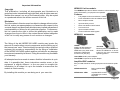
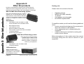
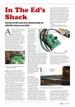
DSP Noise Cancellation
bhi Ltd
P.O. Box 136
Bexhill on Sea
East Sussex
TN39 3WD
tel: +44 (0)870 240 72 58
fax: +44 (0)870 240 72 59
[email protected]
www.bhi-ltd.co.uk
Page 36
NEDSP1061-KBD Operating Manual
Sound Engineering Solutions from bhi
Sound Engineering Solutions
bhi
bhi
NEDSP1061-KBD
Noise Eliminating PCB Module
Installation
and
Operating Manual
Complete with detailed fitting instructions for
Yaesu FT-817, Icom 706 MKII G
and Kenwood TS50
1061-110D
B
NEDSP1061-KBD OperatingIssue
Manual
Page 1
Important Information
Disclaimer
The information in this document is subject to change without notice.
bhi Ltd. makes no representations or warranties with respect to the
contents hereof and specifically disclaims any implied warranties of
merchantability or fitness for any particular purpose. Furthermore,
bhi Ltd. reserves the right to revise this publication and to make
changes from time to time in the content hereof without obligation
of bhi Ltd. to notify any person of such revision or changes.
The fitting of the bhi NEDSP1061-KBD module may involve the
removal of small surface mount components and the drilling out of
the transceivers’ case. This should only be carried out by a qualified
engineer. bhi accepts no responsibility for the fitting or installation
of the NEDSP1061-KBD module and are not liable for any damage
to equipment caused by its fitment. Fitting this module may invalidate
your warranty.
All attempts have been made to ensure that this information is up to
date. It is possible that these instructions contain errors, or the
equipment is slightly different to the one used to compile this
information. In all cases it is up to the installer to ensure that the
module is fitted correctly.
By installing this module you are doing so at your own risk.
Page 2
NEDSP1061-KBD Operating Manual
NEIM1031 In-line module.
The NEIM1031 provides a flexible solution to noise reduction and
easily fits between your quipment and speaker.
Features:
Fully adaptive noise cancellation 9 -35dB
•
•
8 user selectable noise cancellation levels
•
Mono earpiece socket
•
Input sensitivity control
•
Noise cancellation On/Off switch
•
Line level in/out
•
Input overload indication
•
Power on/off with audio bypass.
NEIM1031 accessories.
LSPKR
Quality 20 Watt extension
speaker for use with the
NEIM1031or any other audio
equipment. Fitted with a
3.5mm mono jack plug.
1031-STA
Mounting stand for the NEIM1031.
Allows the NEIM1031 to be adjusted for the most comfortable
operating position.
1030-UKPA UK DC power adapter
1030-EUPA European DC power adapter
Amplified DSP modules.
Easy to install retrofit for existing equipment and extension speakers
NEDSP1062-PCB:
Basic amplified DSP
module.
NEDSP1062 - KBD:
Amplified DSP module
controlled by a 2 button
keyboard.
NEDSP1061-KBD Operating Manual
Page 35
Appendix D Other bhi products.
Copyright
This publication, including all photographs and illustrations is
protected under international copyright laws, with all rights reserved.
Neither this manual, nor any of the material within, may be copied
or reproduced without the written consent of bhi Ltd.
Appendix D
Other bhi products
bhi stock a comprehensive range of audio accessories and
adapters to suit most equipment, please call or visit www.bhiltd.co.uk for more information. Full contact details on back page.
Packing List:
Please check the contents of the box.
Appendix D Other bhi products.
NES10-2 MKII Noise Eliminating speaker.
DSP noise cancellation built into a compact
speaker unit. the unit provides an easy to
install solution to noise reduction and easily
connects to the extension speaker speaker
socket or head phone socket of your
equipment.
Key features:
•
Fully adaptive noise cancellation 9 -35dB
•
8 user selectable noise cancellation levels
•
Mono earpiece socket
•
Input sensitivity control
•
Noise cancellation On/Off switch
•
LED indication of power and noise cancellation
•
12-24VDC operation
•
On/Off audio bypass switch.
•
•
•
•
•
Operating manual
NEDSP1061-KBD assembly
‘Z’ bracket
Self adhesive mounting pads
bhi NEDSP keyboard label
To install this module you will need the following additional
items:
•
service manual/circuit diagram of the equipment in
which the module is to be installed.
•
all the appropriate tools to disassembling the
equipment
•
suitable soldering iron and bits for working with
surface mount devices.
NES5 Noise Eliminating speaker.
Basic plug and go noise cancelling
speaker preset to 20dB of noise
reduction. Easily connecst to the
extension speaker or headphone
socket on your equipment.
Before attempting to fit this module study this manual
thoroughly along with the service manual for your
equipment.
Key features:
Fully adaptive noise cancellation 20dB
•
•
12-24VDC operation
1042 switch box.
Allows up to 6 pieces of
equipment to be connected to
one speaker or inline module. 3
inputs loaded at 8 ohms.
Page 34
NEDSP1061-KBD Operating Manual
NEDSP1061-KBD Operating Manual
Page 3
Contents
Introduction
1.1 NEDSP1061-KBD features
1.2 Limitations
1.3 Audio DSP noise cancellation
6
6
7
Module description
2.1 Module layout
2.2 Connections
2.3 Electrical characteristics
2.4 Controls
2.4.1
Input level
2.4.2
Output level
2.4.3
Beep volume level
2.4.4
Overload LED
2.5 Module mounting
8
8
9
9
9
9
9
9
10
Installation
3.1 Introduction
3.2 Circuit location
3.3 Fitting
3.3.1
Audio connections
3.3.2
Power connections
11
11
11
12
12
13
4.
Setup
14
5.
Troubleshooting
15
6.
Operation
6.1 Introduction
6.2 Operation
6.3 Demonstration mode
6.4 Notes about noise reduction
6.5 Noise reduction level
16
16
16
17
18
18
2.
3.
Page 4
NEDSP1061-KBD Operating Manual
The keyboard is retained using the supplied ‘Z’ bracket,
held in place by the loudspeaker clamp. Fix the dsp
module to the inside of the lid using the self adhesive
tape supplied.
Carefully replace the lid ensuring that none of the wires
are trapped.
NEDSP1061-KBD
‘Z’ clamp
Appendix C Icom 706 MKII G
1.
Figure 7. NEDSP1061-KBD module
mounting.
Affix the bhi DSP label to the
lid, over the keyboard and
LED.
bhi DSP label
NEDSP1061-KBD Operating Manual
Page 33
Drill the keyboard holes in the case lid as shown in the
following diagram. Ensure the holes are de-burred.
7.
Machining drawings
19
3.5mm
Appendices
Appendix C Icom 706 MKII G
4.0mm
59
70
5.1
Figure 5. Case lid machining diagram
Appendix A
Yaesu FT-817 fitting instructions
20
Appendix B
Kenwood TS-50 fitting instructions
26
Appendix C
Icom 706 MKII G fitting instructions
30
Appendix D
Other bhi products
34
NEDSP1061-KBD Operating Manual
Page 5
Connect the black power lead from the NEDSP1061KBD module to the fan mounting screw, as shown in
figure 6.
NEDSP1061-KBD
0V
connection
Figure 6. 0V connection from the NEDSP1061-KBD
module.
Page 32
NEDSP1061-KBD Operating Manual
1. Introduction.
•
•
•
•
•
•
•
•
•
•
•
Fully adaptive to changing noise environments
Input and output level controls
Input overload indication
Virtually no distortion to speech signal
Up to 35dB of noise cancellation
4 levels of noise reduction
5 – 15V supply range
4.6dB on board gain
Single key operation of all functions
LED indication of DSP level and status
Small size 26mm x 37mm
1.2 Limitations.
This module is designed to pass speech. Other signals
such as data and music will to some degree pass
through, but the integrity of these signals
cannot be guaranteed.
This module is designed to be placed in a low level audio
path only. The module will not drive a loudspeaker or
other high power load (see bhi NEDSP1062 amplified
DSP module).
The unit is single channel (mono).
Page 6
NEDSP1061-KBD Operating Manual
The red power lead for
the NEDSP1061-KBD
is connected to the
PCB. Carefully remove
the solder mask from
the PCB surface in the
position shown in figure
4. (it may be necessary
to lengthen the lead).
Flat cable
J1381
1.1 NEDSP1061-KBD module features:
Cut the white wire
Cut the white wire closest to the front of the
transceiver.
Connect the
NEDSP1061-KBD
screened lead as follows:
Red wire to connector
J1431
Blue wire to remaining Figure 3. J1431 modified
connections.
end of the cut lead.
Screen - cut off.
Insulate both the connections with the supplied rubber
sleeves.
y
,
,
y
Remove solder
mask here
Connect Red
+Ve lead from
the NEDSP1061
here
C1381
C897
The NEDSP1061-KBD is a modular solution to noise
reduction. It incorporates DSP technology to provide up
to 35dB of noise cancellation. The module is controlled
by a single pushbutton with LED indication for ease of
use.
R1169
R1170
Figure 4. PCB modification for power lead
NEDSP1061-KBD Operating Manual
Page 31
Appendix C Icom 706 MKII G
1. Introduction.
Appendix C
Icom 706 MKII G
This module is designed for communication type
applications. The upper frequency limit is 4.5KHz and
therefore not suitable for hi fidelity applications.
1.3 Audio DSP Noise cancellation.
This document should be read in conjunction with the
relevant Icom 706 MKII G technical supplement.
Disconnect the power before commencing.
Remove the 5 screws retaining the top cover.
Disconnect all the loudspeaker connector.
Remove the lid.
The NEDSP1061-KBD
module is inserted into the
audio path on the 4 pin connector J1431. This connec- Figure 1. Loudspeaker
connector
tor can be
located on the right hand side at the front of the main
board.
The following diagrams are taken from actual audio
signals and illustrate how the audio signal is being
processed.
Speech
Noise
Original signal.
Speech with a lot of
background noise
1. Introduction.
Appendix C Icom 706 MKII G
The bhi DSP processes the incoming audio signal and
then differentiates the speech from the noise. The
unwanted noise and interference is then attenuated to
leave only the speech.
Processed speech.
Speech with reduced
noise
Audio connector
Reduced noise
Figure 2. Location of
connector J1431
Page 30
NEDSP1061-KBD Operating Manual
Figure 1. Noise cancellation.
NEDSP1061-KBD Operating Manual
Page 7
2.1 Module Layout.
The following diagram shows the layout of the
NEDSP1061-KBD module.
Overload LED
Input level
(P2)
Screened audio
lead
Push
button
Beep volume
(P3)
Red wire
(5-15VDC)
Bi-colour
LED
M3 Ring Tag
(0V)
3.5mm
diameter
Front
5.1
Figure 2. Module layout.
2.2 Module Connections.
The NEDSP1061-KBD module has five connections.
Red wire:
M3 Tag:
Screened Lead:
5 - 15VDC
0V
Red
Blue
Black
Page 8
Audio In (to module)
Audio Out (from module)
Audio Screen
NEDSP1061-KBD Operating Manual
52.0
2. Module Description.
Output level
(P1)
14. Solder the screen from the DSP board to the ground
on CN10 and insulate with tape.
15. Refit CN10 plug into CN10 socket.
16. Replace the speaker and speaker mounting bracket
making sure no wires are getting pinched.
17. Place two thicknesses of double sided tape to the
front right corner of the speaker bracket and mount
switch PCB (see figure 5).
18. Connect radio to power and aerial and test DSP
board works OK readjust beep, input and output
levels if required. (Details in section 4 page 14)
19. Drill the top cover as detailed below.
20. Place the cover on the radio and check alignment
of the switch and adjust if necessary.
21. Replace the top cover screws and fit the bhi label.
4mm
diameter
25.0
Figure 6. Switch mounting hole details.
NEDSP1061-KBD Operating Manual
Page 29
Appendix B Kenwood TS50.
2. Module description.
2.3 Electrical characteristics.
Electrical Characteristics
Parameter
V in
Supply voltage
Iin
Supply current
In
Audio input signal
Out
Audio output signal
(1.7 Xs input max)
Min
Typ
Max
Units
5
9
15
V
45
50
mA
50
300
Vrms
630
Vrms
Table 1. NEDSP1061-KBD Electrical characeristics
2.4 Controls.
Controls are provided to allow the NEDSP1061-KBD to
be integrated in to the target system. 3 level controls are
provided.
2.4.1
Input Level:
To set the audio level to the optimum level for the DSP.
2.4.2
Output Level:
To match the output level of the DSP module to that of
the following stage.
Switch
2.4.3
Beep volume level:
Allows the user to adjust the beep volume control to suit.
The beep volume can be reduced to zero if required.
The modules are factory set to the maximum level.
Figure 5. Switch mounting detail.
Turning the potentiometers anti clock wise will increase
the levels.
Page 28
NEDSP1061-KBD Operating Manual
NEDSP1061-KBD Operating Manual
Page 9
2. Module Description.
Appendix B Kenwood TS50.
Figure 4. CN10 wiring detail.
10. Strip and tin the two ends of the clipped lead.
11. Remove some insulation from the CN10 ground
wire and tin.
12. Solder the red audio wire from the DSP board to
the lead coming out of the plug and insulate with
tape.
13. Solder the blue audio wire from the DSP board to
the remaining lead and insulate with tape.
Description
Note:
The potentiometers do not have end stops. It is possible
to set the potentiometer in a dead band between the
ends, resulting in the audio being lost, continue rotating
and the audio will return.
Earth Screw
Figure 2. Location of earth point.
2.5 Module mounting.
The DSP module has four mounting holes that can be
used to retain the unit inside the equipment. Alternatively
a self adhesive pad is supplied to allow the module to be
mounted in a convenient position - without the need for
drilling.
Two holes need to be drilled in the casing of the
equipment for the keyboard. Hole sizes and positions
can be found in section 7 - page 19.
The keyboard can retained using the supplied ‘Z’ bracket
or alternatively retained using a suitable adhesive, or the
mounting pads supplied.
In some equipment it may be possible to clamp the
bracket under the loudspeaker bracket (e.g. FT-817)
Cover the keyboard holes with the supplied self adhesive
label.
Page 10
NEDSP1061-KBD Operating Manual
Figure 3. Position of red wire.
7.
8.
9.
Carefully scrape the solder mask off the track to
expose the copper.
Solder the red lead of the DSP board to this point.
Remove the plug from CN10 and clip the white wire
that is next to the ground in the middle.
NEDSP1061-KBD Operating Manual
Page 27
Appendix B Kenwood TS50.
2. Module Description.
2.4.4
Overload LED.
The overload LED circuit monitors the amplitude of the
audio level entering the DSP module. The LED will
illuminate when the amplitude exceeds the maximum
permitted level. If the amplitude is increased further the
DSP will clamp the audio signal to prevent damage to
the DSP input. This will cause the audio signal to become
distorted. The optimum level is achieved when the
loudest peaks of the input audio, just cause the LED to
glow.
Appendix B
Kenwood TS50
Have the front of radio facing you and refer to the
photographs in this manual to assist with the board
installation.
4.
Remove the top cover from the radio.
Remove speaker and speaker mount.
Fix double sided tape to the bottom of the DSP
board (DSP chip side) making sure the tape lines
up with the edges of the board.
Fit the DSP board as shown in figure 1.
3.1 Introduction.
Before commencing installation study the equipment’s
service manual/circuit diagram thoroughly to familiarise
yourself with the circuit diagram and disassembly
procedure. Detailed information for fitment into specific
equipment is available in the appendices of this manual.
Audio source
Audio out
Pre amp
NEDSP1061
Power amp
C127
C126
Figure 3. Basic connection diagram
CN10
DSP module
Audio source
Audio out
3. Installation.
Appendix B Kenwood TS50.
1.
2.
3.
3. Installation
Power amp
Pre amp
Figure 1. Location of C126,C127, CN10 and DSP module
5.
6.
Remove the mounting screw for the fan and attach
the ground lug at this point.
Locate the pc board trace coming from pin 8 of the
audio amp chip (IC7) This track is between C127
elect cap and C126 elect surface mount cap. There
is a + printed on top of this track for C126 (see
figure 1).
Page 26
NEDSP1061-KBD Operating Manual
NEDSP1061
Remove this
capacitor
Figure 4. NEDSP1061-KBD Audio path
NEDSP1061-KBD Operating Manual
Page 11
For optimum performance provide the module with a
constant amplitude signal, for example before the volume
control.
Remove this
capacitor
Pre amp
Keyboard mounting using the ‘Z’ bracket.
•
Slacken the screws retaining the loudspeaker
•
Position keyboard into the lid cutouts
•
Place the ‘Z’ bracket over the keyboard, carefully
easing the bracket into position
•
Retighten the loudspeaker bracket.
Clamp ‘Z’ bracket
Blue
Red
Screen
Power amp
Volume
Loudspeaker
Fit the NEDSP1061-KBD
module in place of
the coupling capacitor
Figure 5. NEDSP1061KBD recommended
position.
Figure 4. Keyboard mounting
3.3 Fitting.
After locating a suitable location for the module in the
circuit, refer to the service manual for disassembly
information.
3.3.1
Audio connections.
Carefully remove the chosen coupling capacitor, taking
care to not damage the PCB pads. Solder the blue wire
from the screened lead to the power amp side of the
capacitor and the red to the other.
The black wire should be connected to a convenient 0V
Figure 5. Hole drilling detail
Page 12
NEDSP1061-KBD Operating Manual
NEDSP1061-KBD Operating Manual
‘Z’ bracket
Front edge of lid
3. Installation.
Note:
On some modern receivers/transceivers the volume
control is digital and doesn’t operate in the audio path.
Contact the manufacturer for advise for the most suitable
position for the DSP module..
Loudspeaker bracket
Page 25
Appendix A Yaesu FT-817.
NEDSP1061
3.3.2
Power connections.
5 - 15VDC (9V typically) is required to operate the
module. The lower the voltage, the less heat the module
will have to dissipate.
Locate a convenient point to connect the power. Ensure
that this point is connected after the power switch,
otherwise the DSP module will be drawing power all the
time, and may discharge the batteries (where fitted).
Connect the red wire to this point.
The 0V connection is formed using the M3 ring tag.
Locate a suitable 0V point (such as a PCB retaining screw
that is fixed into the chassis).
3. Installation.
When routing the wires, ensure they are away from strong
sources of RF or high voltage.
Screened lead
Keyboard assembly
NEDSP1061 preferred
postition
(mount DSP down)
Ensure these wires do not
foul the lid when fitted
M3 ring tag
Power lead
FT-817 speaker connector
Alternative location fixed to lid
(mount DSP up)
Appendix A Yaesu FT-817.
Keep this area clear
for speaker
Page 24
connection (this screens the cable and acts as a
mechanical fixing for the cable, protecting the capacitor
pads).
Figure 3. Fitted module
NEDSP1061-KBD Operating Manual
NEDSP1061-KBD Operating Manual
Page 13
4. Setup
Tune the equipment to a strong signal.
Switch off the noise reduction (LED will illuminate RED).
Adjust the input P2 until the overload led illuminates.
Back off the potentiometer approximately a 1/4 of a turn.
Adjust P1 to give the correct listening volume, without
distortion.
Adjust P3 to give the desired beep volume level, or off if
required.
Replace the main unit PCB.
The NEDSP1061-KBD screened lead fits in the cut out
provided for the front antenna connector.
Replace the main unit, connections, and all screws
except the front right hand screw.
Drill the holes for the lid, as per the drawing on page 25
of this manual.
The keyboard is mounted using the supplied ‘Z’ bracket.
See page 25 for more information on installing the
bracket. Alternatively use hot melt, epoxy or any suitable
adhesive affix the small keyboard to the inside of the lid.
Taking care to not get adhesive on the upper surface of
the lid, switch or LED.
Allow this to cure before continuing.
4. Setup.
The NEDSP1061-KBD can be
affixed in two positions.
The preferred position is in the
location of the optional filter. This
provides the more mechanically
secure location. If the optional filter
is (or is going to be) installed the module can be installed
on the inside of the lid (see photo).
Solder the red (power) lead to the drain of Q1082
(TP1084).
Connect M3 ring tag (0V leads) using the right front screw.
Affix the NEDSP1061-KBD module using the supplied
self adhesive pad in the chosen location.
Page 14
NEDSP1061-KBD Operating Manual
NEDSP1061-KBD Operating Manual
Page 23
Appendix A Yaesu FT-817.
The levels come factory set to the maximum position.
This should be adequate for most applications. However
the module can be adjusted as follows.
5. Troubleshooting
Location of
C1338
on lower side
of main unit
Start
Audio
Distortion
Overload
LED
Illuminates
Connect Red (+Ve wire)
to this point (see page
23)
Q1057
Yes
Reduce input
level using P2
No
Reduce output
level using P1
5. Troubleshooting.
Appendix A Yaesu FT-817.
Location of
Q1082 (TP1084)
on upper side of
main unit
Lower side of main unit
Screen
Blue wire
Yes
Distortion
Red wire
R1482
No
Q1084
End
Figure 2.NEDSP1061-KBD connection detail
Page 22
NEDSP1061-KBD Operating Manual
Figure 6. Troubleshooting flowchart.
NEDSP1061-KBD Operating Manual
Page 15
6. Operation
The mode of operation is indicated both visually and
audibly.
6. Operation.
The LED is illuminated red when the noise cancellation
is off.
When the noise cancellation level is changed the LED
will flash green to indicate which level has been selected.
Simultaneously the DSP will beep to give audible
indication of DSP level. This allows the operator to
change the DSP level without having to look at the LED
to see which level has been selected.
A short beep is emitted to acknowledge a button press.
The module will store the current DSP level, and will
return to this level when the equipment is switched on.
Carefully remove the capacitor.
Connect the screened lead from the NEDSP1061-KBD
module as follows:
Red lead - to R1482 side of C1338 (audio in)
Blue lead to the other side of C1338 (audio out)
Screen to the grounded connection close to the
capacitor.
•
•
•
See figure 1 below for details.
NEDSP1061
R1268
15K
C1460
100p
Q1094
R1482
1K
-
6.2 Operation.
Switch on the equipment.
The LED will illuminate red to indicate the noise
cancellation is off. The unit will flash/beep to indicate the
DSP filter level last used.
Remove
C1338
100n
To
Volume
control
+
R1459
10K
R1317
100K
Figure 1. Schematic detail. FT-817
Page 16
NEDSP1061-KBD Operating Manual
NEDSP1061-KBD Operating Manual
Page 21
Appendix A Yaesu FT-817.
Single press turns the noise cancellation on/off.
Holding down the button changes the DSP filter
level.
The following diagram shows the position of the component.
Blue wire
•
•
To place the module into the audio path it is necessary
to remove the audio signal coupling capacitor C1338.
Red wire
6.1 Introduction.
All functions of the NEDSP1061-KBD are controlled by
a single button.
Appendix A
Yaesu FT-817
Noise cancellation on/off.
Press and release the button and the led will extinguish,
and the noise cancellation will be activated. A short beep
will acknowledge the key press.
This document should be read in conjunction with the
relevant Yaesu FT-817 technical supplement.
The bhi NEDSP1061-KBD module is inserted into the
audio path of the transceiver, at a point before the volume
control. To access this point it is necessary to remove
the main unit.
Remove any fitted batteries or NiCad pack before
commencing installation.
Remove the top and bottom covers.
Remove the 5 main unit fixing screws.
Disconnect all connections - apart from the front unit
ribbon cable.
Hinge the main unit forward, over the front unit ribbon
cable.
Page 20
NEDSP1061-KBD Operating Manual
6.3. Demonstration mode.
The NEDSP1061-KBD module features 2 preset
demonstration modes. These demonstrate the noise
cancellation abilities of the NEDSP1061-KBD module.
6.3.1
Demonstration 1:
Hold down the button and switch on the equipment. After
a short time the unit will emit a 2 tone beep. Release the
button. The unit is now in demonstration mode 1.
The module will switch the noise cancellation on for 1.5
seconds, then off for 1.5 seconds. It will then move onto
the next level and repeat this continuously through all 4
levels.
This mode a particularly effective when the equipment
is just receiving static, as it demonstrates the attenuation
of white noise at all the levels.
Alternatively tune the equipment into a good quality FM
speech broadcast. This demonstration shows how little
the DSP alters the speech, at any of the levels.
NEDSP1061-KBD Operating Manual
Page 17
6. Operation.
Appendix A Yaesu FT-817.
Changing the filter level.
Hold down the button. The led will flash the filter level,
and if the button is held it will step through all the levels.
When the desired level has been reached release the
button. This new value will be stored in the modules’
memory and will be the default setting the next time the
unit is powered up.
7. Machining details
6.3.2
Demonstration 2:
Follow the procedure as above. Wait for the second 2
tone beep, then release the key.
36.2
30.28
6.3.3
Exiting the demonstration mode.
Hold down the button until the 2 tone beep is heard.
Release the button.
After a short delay the LED will flash indicating the stored
level, as during the normal switch on.
6. Operation.
6.4 Notes about the noise reduction.
When using the module on level 4 some distortion may
be heard. This is quite normal when listening to high
levels of noise at level 4.
DSP physical
dimensions
4 off holes
3mm diameter
7. Machining details.
3.0
24.0
27.4
The noise cancellation is switched on for 3 seconds, then
off for 3 seconds. This loops until the user aborts this
mode.
This is a good demonstration for listening noisy SSB
conversations showing the before and after.
1.52
3.0
In this mode the filter level is set to level 3.
3.5mm
diameter
4mm
diameter
6.5 Noise reduction levels.
5.1
L evel
Tone Reduction
White Noise
Reduction
1
5dB
11dB
2
8dB
13dB
3
21dB
20dB
4
65dB
35dB
Page 18
NEDSP1061-KBD Operating Manual
Keyboard
hole detail
Figure 7. Hole machining details.
NEDSP1061-KBD Operating Manual
Page 19