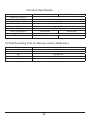
1
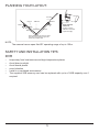
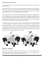
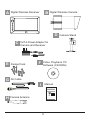
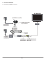
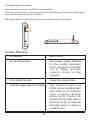
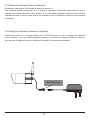
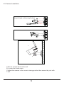
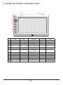
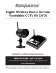
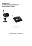
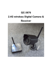
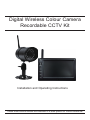
Digital Wireless Colour Camera
Recordable CCTV Kit
Installation and Operating Instructions
These instructions should be retained in a safe place for future reference.
2
CONTENTS
1. INTRODUCTION—3
2. KIT CONTENTS—6
3. INSTALLATION—8
3.1 Contents and Connections 8
3.2 Powering up the system
9
3.3 Setting the Camera Channel (Optional)
3.4 Pairing the Camera to Receiver (Optional)
3.5 Camera Installation 11
10
10
4. MONITOR PANEL INTRODUCTION—12
5. SYSTEM INTRODUCTION—13
5.1 Icon Functions
5.2 System Menu
13
14
6. System Operation —16
6.1 Camera Setup
16
6.2 Recorder Setup
19
6.3 Event List 21
6.4 System Setup
23
6.5 Alarm Buzzer
26
6.6 Pan Tilt Zoom
27
6.7 Memory Card Overwrite
28
7.1 Sec24 Media Player Introduction
7.2 Installation 30
7.3 Playback Recorded File(s) 33
7.4 Channel Disable / Enable Select
29
35
8. System Configuration—36
9.Product Specification—37
10.Total Recording Time for Memory Cards (32GB max.)—37
3
1. INTRODUCTION
The Digital Wireless Colour Camera Recordable CCTV Kit is a wireless security system
designed to view and capture video clips of any motion viewed by the wireless camera and
store them in on a memory card. The wireless camera supplied is colour, weatherproof and
suitable for day/night use for the protection of your home or office, etc.
Please read before you start:
Always use discretion when installing CCTV survillance equipment especially
when there is perceived policy. Enquire regarding local regulations applicable to
the lawful installation of video recording/surveillance. Third party consent may be
required.
WIRELESS DEVICES OPERATING RANGE:
Ensure the signal reception viewed from the wireless camera is the best possible
reception (i.e. no interference lines viewed on the TV) between the camera and
receiver. If necessary reduce the distance between the camera and receiver to
improve overall system performance.
The Wireless Colour Camera Recordable CCTV Kit operating on a secure digital
2.4GHz frequency can greatly reduce interference from products such as wireless
routers, cordless phones, microwave ovens, concrete walls, large scale metal
objects, and furniture.
4
PLANNING YOUR LAYOUT:
Front Door
Receiver
TV/Monitor
Camera 2
Camera 1
Max 5m
Max 5m
15mm diameter
cable hole
(to allow camera
cable and connector
to pass through)
Ensure the distance from camera to power
outlet does not exceed the length of the
camera power adapter cable
NOTE:
The camera has an open field RF operating range of up to 150m.
SAFETY AND INSTALLATION TIPS:
DVR
•
•
•
•
•
•
keep away from heat sources and high temperature places
Avoid direct sunlight
Avoid humid places
avoid vibration
Install in a ventilated environment
The supplied 2GB memory card can be replaced with up to a 32GB capacity one if
required.
5
Camera(s) and DVR
Do not attempt to open the units with the power adaptor plug connected to avoid any risk
of personal injury.
When installing CCTV camera(s), always follow manufacturer's advice when using power
tools, steps, ladders, etc. and wear suitable protective equipment (e.g. safety goggles)
when drilling holes. Before drilling holes through walls check for hidden electricity cables
and water pipes. The use of cable/pipe detector is advisable.
It is also advisable to avoid exposing any cameras to extreme weather conditions (e.g,
under a gutter which is prone to any water leaks). When installing any cameras with this
unit, it is advisable to use cable conduit to protect any video/power extension cables
from being exposed externally and to prevent/reduce the chances of the cables being
tampered with. After drilling any hole though an external wall for a cable, ensure the hole
is sealed up around the cable using a sealant to prevent drafts.
To prevent a fire or electrical shock hazard, do not attempt to open the housing while
the unit is exposed to rain, water or wet conditions. There are no user serviceable
parts inside. Refer servicing to qualified service personnel. Avoid pointing the
camera(s) directly at the sun or any bushes, tree branches or moving objects that might
unnecessary cause the DVR to record due to winds for example. The system also
provides "Masking" function, and the user may screen out motion detection area in parts
of the picture which motion detection is not required.
NIGHT VISION:
The camera has built-in infra-red LEDs to allow you to view at night for 24hrs
surveillance. The LEDs will automatically activate at night and the picture viewed will turn
to black and whit. The night viewing range is up to 5-8m.
6
2. KIT CONTENTS
A
1 x 7" LCD Monitor (Receiver)
B
1 x Digital Wireless Cameras
C
2 x 5V/1A Power Adapter for Camera and Receiver
D
1 x Camera Stands
E
1 x Fixings Pack
F
1 x Video Playback PC Software(CD-ROM)
G
1 x AV Cable for TV Output
H
1 x Camera Antennas
I
1 x Manual
Tools Required:
Electric drill
5mm masonry drill bit
15mm masonry drill bit
No.2 Philips screwdriver
Hammer
Bradawl
7
A
B
Digital Wireless Receiver
Digital Wireless Camera
D
C
5V/1A Power Adapter for
Camera and Receiver
E
Fixings Pack
G
AV Cable
F
Video Playback PC
Software (CD-ROM)
I
Manual
Digital Wireless Colour Camera
Recordable CCTV Kit CWD3
H
Camera Stand
Installation and Operating Instructions
Camera Antenna
These instructions should be retained in a safe place for future reference.
8
3. INSTALLATION
3.1 Contents and Connections
TV / MONITOR
WIRELESS CAMERA
Screw the Camera Bracket
clockwise on to the lower
body of the Camera
to Wireless Cammera
Camera Power
Supply Adaptor
Video Signal
to Input
WIRELESS
RECEIVER
Turn power
on here
Receiver
Power Supply
Adaptor
Connect to
DC 5V/1A port
on Wireless
Receiver
Connect to
3.5mm Phone
Jack on Wireless
Receiver
Wireless
Receiver
Connector Cable
9
Connect to Audio Input on TV
Yellow = Video
White = Audio
3.2 Powering up the system
Insert the memory card into the DVR if not already fitted
Press and Hold power key for one second to power hold the power. Press and hold the power
key for two seconds to power off the system.
After system power on, adjust the camera viewing position again if necessary.
Trouble Shooting
PROBLEM
SOLUTION
No camera picture
The power supply adaptor
for the monitor camera(s)
is not plugged in.Camera
out of range. Locate
camera closer to the
receiver.
Poor picture quality
Clean the camera lens.
A white image appears at night
The camera's infra-red
LEDs shine invisible light
that reflects of surfaces
such as glass causing
white light. Place the
camera on the other side of
windows to try to improve
the night vision or place in
a well lit area.
10
3.3 Setting the Camera Channel (Optional)
All wireless cameras will be supplied preset to channel 1.
The wireless monitor supports up to 4 wireless cameras. Follow the step below to set or
change the monitor channel of the camera. If you are adding another camera to link with the
supplied monitor in this kit, then ensure its channel is set to a different channel to the existing
camera(s).
3.4 Pairing the Camera to Receiver (Optional)
Follow the steps in 6.1 Camera Setup (p.16) SETUP section to set or change the channel
of the camera. If you are adding another camera to link with the supplied receiver in this kit,
then ensure its channel is set to a different channel to the existing camera(s).
Pairing Key
11
3.5 Camera Installation
Attach Stand to Mounting Surface
C
B
A.Secure camera stand on the wall
B. Loosen the thumb screw
C.Adjust the camera to the correct viewing position then secure the joint with
T-bolt.
12
4. MONITOR PANEL INTRODUCTION
6
12
1
2
3
4
5
7
8
9
10
11
Display
1
2
3 Switch Channel
4
VOL Down
5
6
Menu
VOL Up
7 Switch Channel
8
ESC
9
REC/STOP
10
ZOOM
11
ALARM
12
Menu
Playback
Cursor UP
Cursor Left
Fast Forward
VOL Down
Switch Display CH
PLAY / PAUSE
VOL Up
Switch Display CH
Fast Backward
Previous
DEL
Next
OK / ENTER
Cursor Right
Cursor Down
EXIT
REC Mode
Other
Link indicator
Power indicator
STOP
Power Button
13
5. SYSTEM INTRODUCTION
5.1 Icon Functions
1
01-01-2011 AM12:54:29
(Display Icon)
1.
Signal Indicator
2. 1 Channel Indicator
3.
Recording Indicator
4.
Audio Channel Indicator
5. Display mode
QUAD Display
Scan Display
1 Single Display
6. Audio Volume (Seven volume levels)
= Full Volume
= 1/2 Volume
= Mute
7. Receiver Power Indicator
Power indicator will indicate 100% when adaptor in use
IIII = 100% Strength
8. System Time
9. ZOOM Indicator
PTZ X 1 Indicator
PTZ X2 Indicator
14
5.2 System Menu
[Main Menu]
Press MENU to enter main menu.
After entering [MAIN MENU] system will highlight EVENT LIST by default. System will idle
in [MAIN MENU] for 2 minutes before exiting [MAIN MENU].
Use ▲▼◄► to select, Press MENU to confirm selection and to enter sub-menu.
CAMERA SETUP
Press MENU to CAMERA SETUP Sub Menu
RECORDER SETUP
Press MENU to RECORDER SETUP Sub Menu
15
EVENT LIST
Press MENU to enter EVENT LIST
SYSTEM SETUP
Press MENU to enter SYSTEM SETUP
ALARM BUZZER
Press MENU to turn ALARM BUZZER ON / OFF for when motion is detected
PAN TILT ZOOM
Press MENU to enter single camera PAN TILT ZOOM mode
16
SCAN ACTIVATED CAMERAS
Press MENU to scan activated cameras in full screen mode.
MEMORY CARD OVERWRITE
Press MENU to set memory card overwrite ON or OFF.
6. System Operation
6.1 Camera Setup
Select CAMERA SETUP, press MENU key once to enter sub-menu.
17
Use▼▲to select the camera to set up (1-4).
Use◄►to select [PAIRING] [BRIGHTNESS] [CAMERA ON/OFF]
Camera Pairing
With PAIRING section highlighted, press MENU key once to begin camera pairing (pair
LED on camera will blink once and following with LED blinking continuously indicating
data transmission in process.
System will confirm pairing process is successful with "PAIRED" displaying on screen.
System will indicate pairing process failed with "PAIRING FAIL" displaying on screen.
Press ESC to return to main menu.
18
Camera Brightness Adjustment
With BRIGHTNESS section highlighted, use ▼▲ to adjust camera brightness.
Press ESC to return to main menu.
Camera Activation
With ACTIVATION section highlighted, use ▼▲ to enable or disable camera.
Press ESC to return to main menu.
NOTE:
Ensure the cameras are paired to the receiver for SCAN or QUAD to function
properly (camera "ON" can only be selected when camera has been paired to
system.).
19
6.2 Recorder Setup
Record Schedule
Use▲▼◄► to select and press MENU to enter schedule setup.There are three
different recording options available to chose from. First highlight the time period and
press MENU key to switch between different recording mode.
M: MOTION (REC only when motion detected)
S: SCHEDULE (continuous REC)
X: MANUAL (manual REC)
The system will record video from all 4 channels simultaneously with MOTION,
SCHEDULE and MANUAL record modes. One of the four channels will have audio
available.
When the system performing MOTION record, audio will automatically switch to the
channel triggering by motion.
Recording cannot be stopped until 30 seconds after recording started. This
mandatory system operation is designed to prolong the overall life of memory card.
To stop recording, press REC/DEL once. To remove memory card, please power off
system first.
If under SCHEDULE record mode, the system will automatically resume recording 60
seconds after recording stopped manually. If under MOTION record mode, system
will resume motion detection function 60 seconds after recording stopped manually.
Recording must be stopped before user can enter system main menu and system will
resume QUAD mode after idling for two minutes.
20
Motion Detection Sensitivity
Select RECORDER SETUP, press MENU to enter.
Use ▲▼ to select MOTION DETECTION SENSITIVITY section
Use ◄► to highlight camera for setup
Use ▲▼ to adjust sensitivity level: OFF / LV1 / LV2 / LV3 (LV3 is most sensitive)
Press ESC to save and exit
Format Memory Card
Select RECORDER SETUP, press MENU to enter
Use ▲▼ to select FORMAT STORAGE, press MENU to enter
Press MENU again to confirm and begin formatting memory card
Press ESC to exit
NOTE:
If a new memory card is used then it must be formatted first here before use.
Setup Masking Area
Select RECORDER SETUP, press MENU to enter.
Use ▲▼ to select MASKING AREA section
Use ◄► to highlight camera for setup, press MENU to enter
Use ◄► ▲▼ to highlight the grid for no motion detection in this area. Use MENU
key to mask/unmask grid(s). Movements taking place inside masked area will be
ignored.Use ◄►▲▼ to select another grid for setup or press ESC to save and exit
21
Record Time
Select RECORDER SETUP, press MENU to enter.
Use ▲▼ to select RECORD TIME section
Use ◄► to highlight recording period: 2 Min / 5 Min / 10 MIN, press
MENU to confirm
Press ESC to save and exit
6.3 Event List
Playback
Use ◄► to highlight desired DATE index for playback
Press MENU to confirm selection and enter selected folder.
Press ◄► to select Hour (each block represent one hour time), Press MENU
to enter
Use ◄► to highlight desired HOUR for playback.
Press MENU to confirm selection and enter selected folder.
NOTE:
Each RECORDED FILE folder is indicated with file start / end time and type of
file recorded.
22
(1) Starting / Time:
Start Time = PM10:33
End Time = PM10:43
(2) The type of recorded file (Schedule / Motion / Manual) is indicated by:
= Channel 1 is SCHEDULE recorded file
= Channel 1 is MOTION recorded file
PM 10:33
PM 10:43
1
2
3
=Channel 1, 2, 3 and 4 are MANUAL (C = Continous) recorded files
4
X
To playback recorded file, use ◄► to highlight RECORDED FILE.
Press MENU to confirm selection and playback selected file.
■田 □1 □2 □3 □4 = All channel playback
For single camera display, press MENU once after playback started to PAUSE.
Use ◄► to select from channel to channel.
Channel indicator (bottom left screen) will indicate the channel number selected.
□田 ■1 □2 □3 □4 = Channel 1 playback in full screen
□田 □1 ■2 □3 □4 = Channel 2 playback in full screen
□田 □1 □2 ■3 □4 = Channel 3 playback in full screen
□田 □1 □2 □3 ■4 = Channel 4 playback in full screen
NOTE:
(1) For other control functions available during playback mode, please refer to section 4
- MONITOR PANEL INTRODUCTION (p.12).
(2) The CD provided is for playing back the recorded file(s) from the memory card on a
PC.
23
6.4 System Setup
Date and Time
Select SYSTEM SETUP, press MENU to enter.
Use ▲▼ to highlight DATE AND TIME, press MENU to enter.
Use ◄► to highlight adjust: YEAR / MONTH / DATE / HOUR / MINUTE, use ▲▼ to
adjust each section and press MENU to confirm adjustment.
Press ESC to save and exit
TV Out System (NTSC/PAL)
Use the supplied A/V output cable to display the system on a TV/monitor if required.
Select SYSTEM SETUP, press MENU to enter.
Use ▲▼ to select TV OUTPUT.
Use ◄► to highlight NTSC or PAL, press MENU to confirm selection.
Press ESC to save and exit.
NOTE:
Changing the TV system may affect display image scale.
24
Power Saving
(5 Minutes)
(10 Minutes)
(Always ON)
Select SYSTEM SETUP, press MENU to enter.
Use ▲▼ to select POWER SAVING
Use ◄► to select SCREEN OFF AFTER 5 MINUTES IDLE / SCREEN OFF AFTER
10 MINUTES IDEL / SCREEN ALWAYS ON, press MENU to confirm setting.
Press ESC to save and exit.
Multi Channels Idle Display
This is used to set the display mode for each camera channel when the display is left
idle.
25
(Display QUAD mode)
(5 sec Intervals)
(10 sec Intervals)
(15 sec Intervals)
Select SYSTEM SETUP, press MENU to enter.
Use ▲▼ to select MULTI CHANNELS IDLE DISPLAY.
Use ◄► to select: DISPLAY QUAD DURING IDLE / AT 5 SEC INTERVALS / AT 10 SEC
INTERVALS / AT 15 SEC INTERVALS, press MENU to confirm selection.
Press ESC to save and exit.
NOTE:
(1) Camera ON/OFF setting in CAMERA SETUP section will affect which
camera(s) can be displayed during IDLE DISPLAY.
(2) Audio (single channel at anytime) will be available during QUAD mode (by
default on channel 1 or the next available channel with camera paired to system),
single FULL screen mode (auto switch to channel viewing at the time), or channel
triggered by motion.
(3) Audio channel will stay connected until channel switched.
(4) If set to 5/10/15 sec. interval then select SCAN ACTIVATED CAMERAS (p.27)
to achieve this display mode.
26
Default
Select SYSTEM SETUP, press MENU to enter.
Use ▲▼ to select DEFAULT.
Use ◄► to select the system language for SYSTEM RESTORE, press MENU to confirm
selection and system will restore to factory default.
NOTE:
While SYSTEM RESTORE icon highlighted, system firmware version will be displayed
(example: VER:11.06.11-21:13:09)
6.5 Alarm Buzzer
Select ALARM BUZZER, press MENU to turn buzzer ON or OFF. When motion is detected by
a camera, then a buzzer sound will be triggered by the monitor.
27
6.6 Pan Tilt Zoom
Select PAN TILT ZOOM, press MENU once to enter ZOOM mode, press MENU again to
zoom in (2X).
When zooming in, use ▲▼ ◄► to select various view areas.
Press MENU to zoom out.
In zoom out (1X), use ▲▼to change available channel
Press ESC to exit ZOOM.
Select SCAN ACTIVATED CAMERAS, press MENU once to begin camera scan mode.
NOTE:
(1) Camera ON/OFF setting in CAMERA SETUP section will affect which camera(s) can
be displayed during IDLE DISPLAY. See p.25 for the display inteval setup.
(2) The system will automatically activate QUAD display if recording function is
activated.
28
6.7 Memory Card Overwrite
When the memory is full, by enabling this function will allow you to overwrite the earlist
files with the recent ones.
Select MEMORY CARD OVERWRITE, press MENU once to activate overwrite function and
press MENU again to de-activate.
NOTE:
(1) One of the following examples will appear on display screen a. 1.89GB - space
available on memory card. b. ERROR - either memory card is missing, locked or
damaged.
(2) When memory card is full, the system will display "MEMORY FULL PLEASE
FORMAT" on the preview screen if overwrite is not enabled.
29
7.PLAYBACK SOFTWARE
Sec24 Media Player is specifically designed to playback recorded files from the Digital
Wireless Colour Camera Recordable CCTV Kit you have purchased on PC. Others cannot
playback recorded files without Sec24 Media Player; this is for you privacy protection.
7.1 Sec24 Media Player Introduction
1
2
3
4
5
6
1.
2.
3.
4.
5.
6.
7.
8.
9.
10.
11.
12.
13.
7
8
9
10
11
Channel 1 Playback Screen
Channel 2 Playback Screen
Channel 3 Playback Screen
Channel 4 Playback Screen
Playback Progress Bar
Play
Pause
Stop
Fast Rewind
Fast Forward
Load Recorded File(s)
Replay Last File
Channel Enable / Disable Select
30
12
13
7.2 Installation
Insert CD came with the package into the CD-ROM on PC.
Click on MY COMPUTER, double click on the drive where the CD-ROM assigned by PC (for
example: E;\).
In E drive you will find the following icon. Please follow installation procedure A to X to
complete installation.
NOTE:
(1) If Window 7 is running on your PC, please right click on icon “20111027_Sec24
Media Player_v1.0.9.44” and select “Run as administrator” option first to begin
installation.
31
(2) Following error message will appear if user did not select “Run as administrator”
option first before starting the installation.
A. Double click the icon to start installation process.
32
B. Click “Next” and following window will appear on screen.
Following window will appear on screen after installation completes. Click “Finish” to
complete the installation.
33
7.3 Playback Recorded File(s)
Double click Sec24 Media Player icon on desktop to start software
34
Click on “Load” to import and playback previous recorded files (SNX files) already stored on
PC.
35
7.4 Channel Disable / Enable Select
During playback, all four channels will playback at once. For privacy concern, user is able to
manually disable audio channel and/or video channel(s).
Select Audio to turn off sound
• Select 1 to turn off video image from channel 1
• Select 2 to turn off video image from channel 2
• Select 3 to turn off video image from channel 3
• Select 4 to turn off video image from channel 4
36
8. System Configuration
Channel 1
Activation
Channel 2
Camera Setup
Brightness
Channel 3
Pairing
Channel 4
Schedule
Cam2
Cam3
Cam4
Cam1
Cam2
Cam3
Cam4
2 minute
5 minutes
10 minutes
Cam1
Motion sensitivity
Recorder Setup
Go
SD Card Format
Motion Area
Record Time
Event List
(LIFO)
Date
Hour
Files
Play Mode
YYYY
MM
DD
5 minute
10 minutes
NEVER
QUAD
Scan 5 Sec
Scan 10 Sec
NTSC OUT
PAL OUT
HH (AM/PM)
Date / Time
Power Save
System Setup
Idle Display
Language Default
TV Output
Alarm
Buzzer
ON
OFF
Pan/Tilt/Zoom
Overwrite
ON
OFF
Scan
37
Scan 15 Sec
MM
9.Product Specification
Camera
Receiver
Maximum Channels
Communication Range
Monitor Resolution
Camera Resolution
4
150 metres in open space
800X480
640X480
Operating Temperature
Operating Voltage
Curren Consumption
Night Vision
Dimension
-10°C ~ 50°C
DC 5V / 1A
550mA(max)
860mA(max)
5-8m
130x61x67 mm
200x122x25 mm
10.Total Recording Time for Memory Cards (32GB max.)
Micro SD Card Capacity
1G
2G
8G
16G
32G
640 x 480(VGA)
60Minutes
110 Minutes
400 Minutes
950 Minutes
1880 Minutes
38