1
Model 2651A High Power
System SourceMeter® Instrument
99 Washington Street
Melrose, MA 02176
Phone 781-665-1400
Toll Free 1-800-517-8431
User’s Manual
2651A-900-01 Rev. A / March 2011
A
G R E A T E R
Visit us at www.TestEquipmentDepot.com
M E A S U R E
O F
C O N F I D E N C E
Model 2651A
High Power System SourceMeter® Instrument
User's Manual
© 2011, Keithley Instruments, Inc.
Cleveland, Ohio, U.S.A.
All rights reserved.
Any unauthorized reproduction, photocopy, or use the information herein, in whole or in part,
without the prior written approval of Keithley Instruments, Inc. is strictly prohibited.
All Keithley Instruments product names are trademarks or registered trademarks of Keithley
Instruments, Inc. Other brand names are trademarks or registered trademarks of their respective
holders.
The Lua 5.0 software and associated documentation files are copyright © 1994-2008, Tecgraf,
PUC-Rio. Terms of license for the Lua software and associated documentation can be accessed at
the Lua licensing site (http://www.lua.org/license.html).
Document number: 2651A-900-01 Rev. A / March 2011
Test Equipment Depot - 800.517.8431 - 99 Washington Street Melrose, MA 02176 - TestEquipmentDepot.com
Safety Precautions
The following safety precautions should be observed before using this product and any associated instrumentation. Although
some instruments and accessories would normally be used with nonhazardous voltages, there are situations where hazardous
conditions may be present.
This product is intended for use by qualified personnel who recognize shock hazards and are familiar with the safety precautions
required to avoid possible injury. Read and follow all installation, operation, and maintenance information carefully before using
the product. Refer to the user documentation for complete product specifications.
If the product is used in a manner not specified, the protection provided by the product warranty may be impaired.
The types of product users are:
Responsible body is the individual or group responsible for the use and maintenance of equipment, for ensuring that the
equipment is operated within its specifications and operating limits, and for ensuring that operators are adequately trained.
Operators use the product for its intended function. They must be trained in electrical safety procedures and proper use of the
instrument. They must be protected from electric shock and contact with hazardous live circuits.
Maintenance personnel perform routine procedures on the product to keep it operating properly, for example, setting the line
voltage or replacing consumable materials. Maintenance procedures are described in the user documentation. The procedures
explicitly state if the operator may perform them. Otherwise, they should be performed only by service personnel.
Service personnel are trained to work on live circuits, perform safe installations, and repair products. Only properly trained
service personnel may perform installation and service procedures.
Keithley Instruments products are designed for use with electrical signals that are rated Measurement Category I and
Measurement Category II, as described in the International Electrotechnical Commission (IEC) Standard IEC 60664. Most
measurement, control, and data I/O signals are Measurement Category I and must not be directly connected to mains voltage or
to voltage sources with high transient over-voltages. Measurement Category II connections require protection for high transient
over-voltages often associated with local AC mains connections. Assume all measurement, control, and data I/O connections are
for connection to Category I sources unless otherwise marked or described in the user documentation.
Exercise extreme caution when a shock hazard is present. Lethal voltage may be present on cable connector jacks or test
fixtures. The American National Standards Institute (ANSI) states that a shock hazard exists when voltage levels greater than
30 V RMS, 42.4 V peak, or 60 VDC are present. A good safety practice is to expect that hazardous voltage is present in any
unknown circuit before measuring.
Operators of this product must be protected from electric shock at all times. The responsible body must ensure that operators
are prevented access and/or insulated from every connection point. In some cases, connections must be exposed to potential
human contact. Product operators in these circumstances must be trained to protect themselves from the risk of electric shock. If
the circuit is capable of operating at or above 1000V, no conductive part of the circuit may be exposed.
Do not connect switching cards directly to unlimited power circuits. They are intended to be used with impedance-limited
sources. NEVER connect switching cards directly to AC mains. When connecting sources to switching cards, install protective
devices to limit fault current and voltage to the card.
Before operating an instrument, ensure that the line cord is connected to a properly-grounded power receptacle. Inspect the
connecting cables, test leads, and jumpers for possible wear, cracks, or breaks before each use.
When installing equipment where access to the main power cord is restricted, such as rack mounting, a separate main input
power disconnect device must be provided in close proximity to the equipment and within easy reach of the operator.
For maximum safety, do not touch the product, test cables, or any other instruments while power is applied to the circuit under
test. ALWAYS remove power from the entire test system and discharge any capacitors before: connecting or disconnecting
cables or jumpers, installing or removing switching cards, or making internal changes, such as installing or removing jumpers.
Do not touch any object that could provide a current path to the common side of the circuit under test or power line (earth)
ground. Always make measurements with dry hands while standing on a dry, insulated surface capable of withstanding the
voltage being measured.
The instrument and accessories must be used in accordance with its specifications and operating instructions, or the safety of
Test Equipment Depot - 800.517.8431 - 99 Washington Street Melrose, MA 02176 - TestEquipmentDepot.com
the equipment may be impaired.
Do not exceed the maximum signal levels of the instruments and accessories, as defined in the specifications and operating
information, and as shown on the instrument or test fixture panels, or switching card.
When fuses are used in a product, replace with the same type and rating for continued protection against fire hazard.
Chassis connections must only be used as shield connections for measuring circuits, NOT as safety earth ground connections.
If you are using a test fixture, keep the lid closed while power is applied to the device under test. Safe operation requires the use
of a lid interlock.
If a
screw is present, connect it to safety earth ground using the wire recommended in the user documentation.
The ! symbol on an instrument means caution, risk of danger. The user should refer to the operating instructions located in the
user documentation in all cases where the symbol is marked on the instrument.
The
symbol on an instrument means caution, risk of electric shock. Use standard safety precautions to avoid personal
contact with these voltages.
The
The
symbol on an instrument shows that the surface may be hot. Avoid personal contact to prevent burns.
symbol indicates a connection terminal to the equipment frame.
If this Hg symbol is on a product, it indicates that mercury is present in the display lamp. Please note that the lamp must be
properly disposed of according to federal, state, and local laws.
The WARNING heading in the user documentation explains dangers that might result in personal injury or death. Always read
the associated information very carefully before performing the indicated procedure.
The CAUTION heading in the user documentation explains hazards that could damage the instrument. Such damage may
invalidate the warranty.
Instrumentation and accessories shall not be connected to humans.
Before performing any maintenance, disconnect the line cord and all test cables.
To maintain protection from electric shock and fire, replacement components in mains circuits — including the power
transformer, test leads, and input jacks — must be purchased from Keithley Instruments. Standard fuses with applicable national
safety approvals may be used if the rating and type are the same. Other components that are not safety-related may be
purchased from other suppliers as long as they are equivalent to the original component (note that selected parts should be
purchased only through Keithley Instruments to maintain accuracy and functionality of the product). If you are unsure about the
applicability of a replacement component, call a Keithley Instruments office for information.
To clean an instrument, use a damp cloth or mild, water-based cleaner. Clean the exterior of the instrument only. Do not apply
cleaner directly to the instrument or allow liquids to enter or spill on the instrument. Products that consist of a circuit board with
no case or chassis (e.g., a data acquisition board for installation into a computer) should never require cleaning if handled
according to instructions. If the board becomes contaminated and operation is affected, the board should be returned to the
factory for proper cleaning/servicing.
11/07
Test Equipment Depot - 800.517.8431 - 99 Washington Street Melrose, MA 02176 - TestEquipmentDepot.com
Table of Contents
Introduction ................................................................................................................. 1-1
Welcome .............................................................................................................................. 1-1
Extended warranty ............................................................................................................... 1-1
Introduction to this manual................................................................................................... 1-1
CD-ROM contents................................................................................................................ 1-2
Organization of manual sections.......................................................................................... 1-2
Model 2651A applications .................................................................................................... 1-2
Using the front-panel interface.................................................................................. 2-1
Introduction .......................................................................................................................... 2-1
Front panel ........................................................................................................................... 2-1
Using the web interface.............................................................................................. 3-1
Introduction .......................................................................................................................... 3-1
Connect to the instrument web interface ............................................................................. 3-1
Web interface home page.................................................................................................... 3-2
IP configuration tab .............................................................................................................. 3-2
TSB Embedded.................................................................................................................... 3-3
Create a script using TSB Embedded ....................................................................................... 3-3
Exercise: Create and run a script with TSB Embedded ............................................................ 3-4
Reading buffers.................................................................................................................... 3-7
Exercise: Retrieve readings from a buffer ................................................................................. 3-7
TSP Express ........................................................................................................................ 3-8
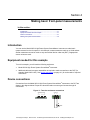
Making basic front-panel measurements ................................................................. 4-1
Introduction .......................................................................................................................... 4-1
Equipment needed for this example .................................................................................... 4-1
Device connections .............................................................................................................. 4-1
Making front-panel measurements ...................................................................................... 4-2
Step 1: Select and set source level ........................................................................................... 4-2
Step 2: Set compliance limit ...................................................................................................... 4-2
Step 3: Select measurement function and range ...................................................................... 4-2
Step 4: Turn output on .............................................................................................................. 4-2
Step 5: Observe readings on the display .................................................................................. 4-3
Step 6: Turn output off .............................................................................................................. 4-3
Test Equipment Depot - 800.517.8431 - 99 Washington Street Melrose, MA 02176 - TestEquipmentDepot.com
Capturing high power pulse waveforms................................................................... 5-1
Introduction to capturing waveforms .................................................................................... 5-1
Equipment needed for this example .................................................................................... 5-1
Set up communication.......................................................................................................... 5-1
Device connections .............................................................................................................. 5-2
Configuring the trigger model............................................................................................... 5-2
Example program code ........................................................................................................ 5-4
Example program usage ...................................................................................................... 5-9
Characterization of power discretes ......................................................................... 6-1
Introduction to power discrete I-V curve testing................................................................... 6-1
Equipment needed for this example .................................................................................... 6-2
Set up communication.......................................................................................................... 6-2
Device connections .............................................................................................................. 6-4
Configuring the trigger model............................................................................................... 6-5
Model 2651A trigger model operation ....................................................................................... 6-7
Series 26xxA instrument's trigger model operation ................................................................... 6-9
Example program code ...................................................................................................... 6-10
Example program usage .................................................................................................... 6-16
Increasing SMU current sourcing ability .................................................................. 7-1
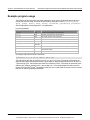
Introduction to combining SMUs .......................................................................................... 7-1
Combining SMUs to increase current sourcing capability ................................................... 7-2
Equipment needed for this example .................................................................................... 7-3
Set up communication.......................................................................................................... 7-3
Device connections .............................................................................................................. 7-4
Configuring the trigger model............................................................................................... 7-6
Master Model 2651A node[1] trigger model operation .............................................................. 7-8
Model 2651A node[2] trigger model operation .......................................................................... 7-8
Series 2600A trigger model operation....................................................................................... 7-9
Example program code ........................................................................................................ 7-9
Example program usage .................................................................................................... 7-16
Troubleshooting FAQs ............................................................................................... 8-1
About this section................................................................................................................. 8-1
Need different line frequency or voltage .............................................................................. 8-1
Can I use external trigger lines? .......................................................................................... 8-1
Test Equipment Depot - 800.517.8431 - 99 Washington Street Melrose, MA 02176 - TestEquipmentDepot.com
Model 2651A High Power System SourceMeter® Instrument User's Manual
Table of Contents
The internal web page of the instrument is not accessible .................................................. 8-1
Save the present state of the instrument ............................................................................. 8-2
LabVIEW driver for the Model 2651A .................................................................................. 8-2
Next steps.................................................................................................................... 9-1
Additional Model 2651A information .................................................................................... 9-1
Index.............................................................................................................................. I-1
2651A-900-01 Rev. A / March 2011
Test Equipment Depot - 800.517.8431 - 99 Washington Street Melrose, MA 02176 - TestEquipmentDepot.com
iii
Section 1
Introduction
In this section:
Welcome .................................................................................. 1-1
Extended warranty ................................................................... 1-1
Introduction to this manual ....................................................... 1-1
CD-ROM contents.................................................................... 1-2
Organization of manual sections .............................................. 1-2
Model 2651A applications ........................................................ 1-2
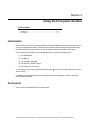
Welcome
Thank you for choosing a Keithley Instruments product. The Model 2651A High Power System
SourceMeter® Instrument provides manufacturers of electronic components and semiconductor
devices a high-power source-measure unit (SMU). A SMU is an instrument that combines source and
measurement capabilities in a single instrument. This combination simplifies test processes by
eliminating synchronization and connection issues associated with multiple instrument solutions. A
Model 2651A provides a scalable, high throughput, highly cost-effective solution for precision DC,
pulse, and low frequency AC source-measure testing that also maintains code compatibility with the
Series 2600A.
Extended warranty
Additional years of warranty coverage are available on many products. These valuable contracts
protect you from unbudgeted service expenses and provide additional years of protection at a fraction
of the price of a repair. Extended warranties are available on new and existing products. Contact your
local Keithley Instruments representative for details.
Introduction to this manual
This manual provides detailed tutorials to help you achieve success with your Keithley Instruments
Model 2651A. In addition, the basics of the two simplest interfaces, the front panel and the web
interface, are provided to familiarize you with the instrument. Select and run all examples in Sections
5, 6, and 7 that are relevant to your intended use and to the equipment you are using.
Some of the examples in this manual may use unfamiliar commands and concepts. For detailed
information about these, refer to the Reference Manual (part number 2651A-901-01) on the Product
Information CD-ROM that came with your instrument.
Test Equipment Depot - 800.517.8431 - 99 Washington Street Melrose, MA 02176 - TestEquipmentDepot.com
CD-ROM contents
Two CD-ROMs are shipped with each Model 2651A order. The Model 2651A Quick Start Guide,
User's Manual, and Reference Manual are provided in PDF format on the Model 2651A Product
Information CD-ROM.
•
Quick Start Guide: Provides unpacking instructions, describes basic connections, and reviews
basic operation information. If you are new to Keithley Instruments equipment, refer to the Quick
Start Guide to take the steps needed to unpack, set up, and verify operation.
•
User's Manual: Provides application examples. If you need a starting point to begin creation of
applications, refer to the User's Manual for a variety of specific examples.
•
Reference Manual: Includes advanced operation topics and maintenance information.
Programmers looking for a command reference, and users looking for an in-depth description of
the way the instrument works (including troubleshooting and optimization), should refer to the
Reference Manual.
A second CD-ROM contains the Test Script Builder script development software (Keithley
Instruments part number KTS-850). Use this CD-ROM to install the Test Script Builder Integrated
Development Environment. This software not only provides an environment to develop a test
program, but also the ability to load the test program onto the instrument. Running a program loaded
on the instrument eliminates the need to send individual commands from the host computer to the
instrument when running a test.
Organization of manual sections
Bookmarks for each manual section have been provided in the PDF (see Adobe® Acrobat® or
Reader® help for information about bookmarks). The manual sections are also listed in the Table of
Contents located at the beginning of this manual.
Model 2651A applications
In addition to being a stand-alone instrument, the Keithley Instruments Model 2651A High Power
System SourceMeter® Instrument can intelligently connect to other instruments and multiple devices.
This manual provides application examples that guide you through several common
instrument-to-instrument scenarios. These applications are presented after the summary information
about the High Power System SourceMeter® Instrument, and include:
•
Making basic front-panel measurements (on page 4-1): Demonstrates the basic measurement
function using a single Model 2651A and a two-terminal device under test (DUT).
•
Capturing high power pulse waveforms (on page 5-1)Capturing high power pulse waveforms:
Demonstrates how to use the Keithley Instruments Model 2651A connected to a control
computer. This example introduces configuration of the instrument's trigger model to make
high-speed measurements of an LED.
Test Equipment Depot - 800.517.8431 - 99 Washington Street Melrose, MA 02176 - TestEquipmentDepot.com
Model 2651A High Power System SourceMeter® Instrument User's Manual
Section 1: Introduction
•
Characterization of power discretes (on page 6-1): Demonstrates how to use the Keithley
Instruments Model 2651A with a second Series 2600A System SourceMeter® instrument to
characterize power MOSFETs and IGBTs. This example introduces the interaction between two
instruments' trigger models. The application performs pulsed measurements, collecting IV curve
data and placing it in a Microsoft® Excel® compatible file format for graphic and analysis.
•
Increasing SMU current sourcing ability (on page 7-1): Demonstrates how to combine two
Keithley Instruments Model 2651A instruments with an additional Series 2600A System
SourceMeter® instrument, and characterizes the resistance of a power MOSFET by sweeping
current up to 100 A.
2651A-900-01 Rev. A / March 2011
Test Equipment Depot - 800.517.8431 - 99 Washington Street Melrose, MA 02176 - TestEquipmentDepot.com
1-3
Section 2
Using the front-panel interface
In this section:
Introduction .............................................................................. 2-1
Front panel ............................................................................... 2-1
Introduction
Before starting this section, complete the tasks outlined in the Model 2651A Quick Start Guide. Once
you have completed those tasks, read this section, which provides enough basic information about
the Model 2651A front-panel interface to work through the examples provided in this manual.
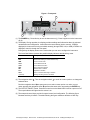
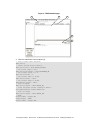
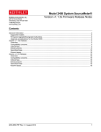
The front panel of the Keithley Instruments Model 2651A contains the following items:
(1) The POWER key
(2) The display
(3) The navigation wheel
(4) The OUTPUT ON/OFF control
(5) The setup and control keys
You can use the keys, display, and the navigation wheel
and set values.
to access, view, and edit the menu items
For additional information about the front panel, see the “General operation” section in the Model
2651A Reference Manual.
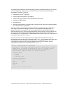
Front panel
The front panel of the Model 2651A is shown below.
Test Equipment Depot - 800.517.8431 - 99 Washington Street Melrose, MA 02176 - TestEquipmentDepot.com
Figure 1: Front panel
2
3
+/MODE
6
0
REL
FILTER
3
0000
DIGITS SPEED
NF
CONFIG
1
LOAD
2
RUN
STORE RECALL
PU
R
TE
N
9
LIMIT
5
AUTO
TO E D IT / E
8
MEAS
4
SH
7
SRC
2651A HIGH POWER SYSTEM SourceMeter ®
N
PU
DISPLAY
TO E DIT / E
R
SrcA:+20.0000 A LimAL10.0000V
POWER
SH
TE
ARM
+3.21000V
TRIG
MENU
EXIT
ENTER
5
1
OU
TPUT
ON
/ OFF
CURSOR
LOCAL
4
(1) The POWER key. Press this key to turn the instrument on (|). Press it again to turn the instrument
off (0).
(2) The display. During operation, the display provides readings and information about the selected
measurement and configuration. It also shows the control status (local or remote). If REM is
displayed, the instrument is being controlled remotely (through GPIB, LAN, or USB). If REM is not
displayed, control is through the front panel.
During setup, the display shows menu choices that you can use to configure the instrument.
The items listed below represent the possible display indicators and what they mean.
Indicator
Meaning
EDIT:
ERR:
REM:
TALK:
LSTN:
SRQ:
REL:
FILT:
AUTO:
* (asterisk):
Unit is in the source editing mode
Questionable reading or invalid calibration step
Unit is in remote mode
Unit is addressed to talk
Unit is addressed to listen
Service request is asserted
Relative mode is enabled
Digital filter is enabled
Source or measure autorange is selected
Readings are being stored in the buffer
(3) The navigation wheel
selected value.
. Turn the navigation wheel
to scroll to a menu option or to change the
Push the navigation wheel
to open menus or to select a menu option or a value. In most
performs the same action as pressing the ENTER key.
cases, pressing the navigation wheel
(4) The OUTPUT ON/OFF control. Press this control to turn the Model 2651A source output on or off.
The output indicator will light when the source is on.
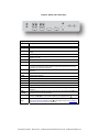
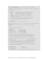
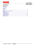
(5) The setup and control keys provide front panel control and configuration. The following figure
illustrates each key's location. The table following the figure contains a definition of each key.
Test Equipment Depot - 800.517.8431 - 99 Washington Street Melrose, MA 02176 - TestEquipmentDepot.com
Figure 2: Setup and control keys
DISPLAY
7
8
9
+/-
SRC
MEAS
LIMIT
MODE
4
5
DIGITS SPEED
CONFIG
1
LOAD
2
RUN
6
0
REL
FILTER
3
0000
STORE RECALL
AUTO
CURSOR
LOCAL
TRIG
MENU
EXIT
ENTER
Key descriptions
Key
Description
DISPLAY
Toggles between the various source-measure displays and the user message mode.
CONFIG
Configures a function or operation.
SRC
Selects the source function (V or A) and places the cursor in the source field for
editing.
MEAS
Cycles through measure functions (V, A, Ω, or W).
LIMIT
MODE
Places the cursor in the compliance limit field for editing. Also selects the limit value
to edit (V, A, or W).
Directly controls the mode.
DIGITS
Cycles through display resolution (4-1/2, 5-1/2, or 6-1/2 digits).
SPEED
Selects either the fast or integrating A/D converter. When the integrating A/D
converter is selected, this key also sets the measurement speed and accuracy by
controlling the measurement aperture.
REL
FILTER
Controls relative measurements. This allows a baseline value to be subtracted from
a reading.
Enables or disables the digital filter. You can use this filter to reduce reading noise.
LOAD
Loads test for execution.
RUN
Runs the last selected factory or user-defined test code.
STORE
Accesses reading buffers and takes readings.
RECALL
Recalls data (or statistics) from CHANA-BUFF1 or CHANA-BUFF2.
TRIG
Triggers readings.
MENU
Accesses the main menu. The main menu can be used to configure many facets of
operation.
EXIT
(LOCAL)
ENTER
Cancels selection and backs out of the menu structure. Also used as a LOCAL key
to take the unit out of remote operation.
Accepts the current selection or brings up the next menu option. In most cases,
Number
keys
.
pressing the ENTER key is the same as pressing the navigation wheel
When enabled, the number keys (0-9, +/-, 0000) allow direct numeric entry in the
to enter EDIT mode (see To change a
EDIT mode. Press the navigation wheel
value using the numeric keypad (on page 2-4)).
Test Equipment Depot - 800.517.8431 - 99 Washington Street Melrose, MA 02176 - TestEquipmentDepot.com
Section 2: Using the front-panel interface
Model 2651A High Power System SourceMeter® Instrument User's Manual
To change a value using the navigation wheel
:
1.
Turn the navigation wheel
when selected).
2.
Press the navigation wheel
3.
Turn the navigation wheel
4.
Press the navigation wheel
5.
Repeat these steps as needed to change the value.
6.
Press the ENTER key or the navigation wheel
to go to the character you want to change (the character blinks
to edit that character.
to change the value.
to enter the change.
when finished changing all the characters.
To change a value using the numeric keypad:
NOTE
The numeric entry method may only be used if the numeric keypad is enabled.
2-4
1.
If the keypad is disabled, press the MENU key, then select DISPLAY > NUMPAD > ENABLE.
2.
Use the CURSOR arrow keys to move the cursor to the value that you want to edit.
3.
Press any of the desired number keys (0-9, +/-, 0000). The cursor moves to the next value on
the right.
4.
Repeat the above steps as required to set the desired values.
5.
Press the ENTER key to select the value or press the EXIT (LOCAL) key to cancel the change.
6.
(Optional) Press the EXIT (LOCAL) key to return to the main menu.
2651A-900-01 Rev. A / March 2011
Test Equipment Depot - 800.517.8431 - 99 Washington Street Melrose, MA 02176 - TestEquipmentDepot.com
Section 3
Using the web interface
In this section:
Introduction .............................................................................. 3-1
Connect to the instrument web interface .................................. 3-1
Web interface home page ........................................................ 3-2
IP configuration tab .................................................................. 3-2
TSB Embedded........................................................................ 3-3
Reading buffers........................................................................ 3-7
TSP Express ............................................................................ 3-8
Introduction
The Model 2651A web interface allows you to review instrument status, control the instrument, and
upgrade the instrument over a LAN connection.
The instrument web page resides in the firmware of the instrument. Changes you make through the
web interface are immediately made in the instrument.
Many examples in this manual and in the Model 2651A Reference Manual can be run through the
TSB Embedded page of the instrument web interface.
Connect to the instrument web interface
NOTE
The instrument web interface requires the web browser plug-in JavaTM SE Runtime Environment
Version 6 or later. The latest version of the plug-in is available from
http://www.java.com/en/download/manual.jsp. Installation files are also available on the Model 2651A
Product Information CD-ROM that came with your instrument.
The instrument web interface uses Java applets and, depending on your browser security settings,
may require your permission to download and install them.
To connect to the instrument web interface, you must have a LAN connection from the computer to
the instrument. See "LAN concepts and settings" in the Model 2651A Reference Manual for more
information about configuring the Model 2651A for a LAN connection, connecting the Model 2651A to
the LAN, and establishing a LAN connection to the instrument.
Test Equipment Depot - 800.517.8431 - 99 Washington Street Melrose, MA 02176 - TestEquipmentDepot.com
Once the Model 2651A is configured correctly and connected to the LAN, you can use the LXI®
Discovery Browser to identify the IP addresses of LXI certified instruments that are set up for
automatic IP address selection. Once identified, you can double-click the IP address in the LXI
Discovery Browser to open the web interface for the instrument. The LXI Discovery Browser is
available on the Keithley Instruments website (http://www.keithley.com).
To locate the LXI Discovery Browser on the Keithley website:
1. Select the Support tab.
2. In the model number box, type 2651A.
3. From the list, select Software and click the search icon. A list of software applications for the
Model 2651A is displayed.
4. See the readme file included with the application for more information.
For more information about the LXI Consortium, see the LXI Consortium website
(http://www.lxistandard.org/).
Alternatively, use the following instructions to connect to the instrument web interface:
1. Confirm the LAN light on the instrument is illuminated. The LAN light is located on the rear panel
as part of the LAN RJ-45 connector.
2. Open an Internet browser, such as Microsoft® Windows® Internet Explorer® (version 6.0 or later
only).
3. If you do not know the IP address, press the MENU key on the instrument front panel and then
select LAN > STATUS > IP-ADDRESS.
4. In the Address box of the Internet browser, enter the IP address of the instrument and press
Enter.
The home page of the instrument web interface is displayed.
Web interface home page
The Welcome page of the web interface gives you basic information about the instrument, including:
•
The instrument model, serial number, firmware revision, calibration date, and LXI information
•
An ID button to help you locate the instrument
•
Links to the instrument web applications, including TSB Embedded, Reading Buffers, Flash
Upgrade, and TSP® Express.
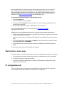
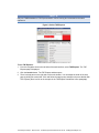
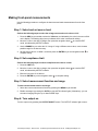
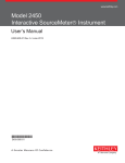
IP configuration tab
The IP Configuration tab provides access to the Model 2651A LAN settings. Refer to the Model
2651A Reference Manual for additional information about IP configuration.
Test Equipment Depot - 800.517.8431 - 99 Washington Street Melrose, MA 02176 - TestEquipmentDepot.com
NOTE
You must reload the page if you change the gateway or subnet mask from the Modify IP configuration
page. If you change the IP address, you must type the new IP address in the address bar before you
can use the web interface again.
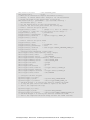
Figure 3: Select IP configuration
TSB Embedded
TSB Embedded is a web application that includes a command-line interface that you can use to issue
commands and interact with the instrument. TSB Embedded also provides a convenient way to create
and manage user scripts. TSB Embedded resides in the instrument. You can use TSB Embedded to
run some of the application examples in other sections of this manual. If you can access the web
interface home page, but cannot use TSB Embedded (or TSP Express), make sure you have the
JavaTM SE Runtime Environment (JRE) Version 6 or later installed on your computer.
Create a script using TSB Embedded
NOTE
If you are using TSB Embedded to create scripts, you do not need to use the commands
loadscript or loadandrunscript and endscript.
Test Equipment Depot - 800.517.8431 - 99 Washington Street Melrose, MA 02176 - TestEquipmentDepot.com
Exercise: Create and run a script with TSB Embedded
The following programming example illustrates the setup and command sequence of a basic
source-measure procedure with the following parameters:
•
Source function and range: Volts, autorange
•
Source output level: 5 V
•
Current compliance limit: 10 mA
•
Measure function and range: Current, 10 mA
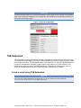
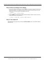
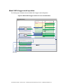
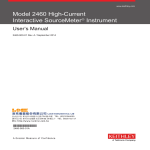
To create and run a sample script with TSB Embedded:
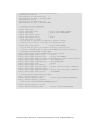
1. From the navigation on the left side of the web interface, select TSB Embedded. The TSB
Embedded page is displayed.
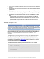
Figure 4: Select TSB Embedded
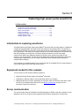
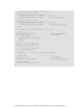
2. To create the example script, enter the name of the TSP script: basic_source_measure at the
location shown by (1) in the following illustration.
Test Equipment Depot - 800.517.8431 - 99 Washington Street Melrose, MA 02176 - TestEquipmentDepot.com
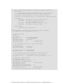
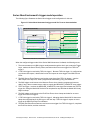
Figure 5: TSB Embedded page
1
2
3
basic_source_measure
basic_source_mea
-- Restore Model 2651A defaults...
4
5
smua.nvbuffer1.clear()
smua.nvbuffer1.appendmode = 1
3. Enter the code below in the script box (2).
-- Restore Model 2651A defaults.
smua.reset()
-- Select voltage source function.
smua.source.func = smua.OUTPUT_DCVOLTS
-- Set source range to auto.
smua.source.autorangev = smua.AUTORANGE_ON
-- Set voltage source to 5 V.
smua.source.levelv = 5
-- Set current limit to 10 mA.
smua.source.limiti = 10e-3
-- Set current range to 10 mA.
smua.measure.rangei = 10e-3
-- Turn on output.
smua.source.output = smua.OUTPUT_ON
-- Print and place current reading in buffer.
print(smua.measure.i(smua.nvbuffer1))
-- Turn off output.
smua.source.output = smua.OUTPUT_OFF
-- Beep.
beeper.enable = beeper.ON
beeper.beep(1, 1200)
beeper.enable = beeper.OFF
Test Equipment Depot - 800.517.8431 - 99 Washington Street Melrose, MA 02176 - TestEquipmentDepot.com
NOTE
Commands and parameters for the Model 2651A are case-sensitive. It is important to type in the
commands exactly as shown to avoid syntax and execution errors.
4. Click Save Script (3). The script is added to the User Scripts list on the left.
Quick Tip
Standard edit functions, such as copy, cut, and paste, work in TSB Embedded.
5. Clear the buffer (4):
•
In the console, type the following and then press Enter.
smua.nvbuffer1.clear()
•
If successful, the command will appear in the Instrument Output box.
6. Set the buffer to append readings (4):
•
In the console, type the following and then press Enter.
smua.nvbuffer1.appendmode = 1
•
If successful, the command will appear in the Instrument Output box.
7. Set the buffer to collect timestamps (4):
•
In the console, type the following and then press Enter.
smua.nvbuffer1.collecttimestamps = 1
•
If successful, the command will appear in the Instrument Output box.
8. Run the script:
•
Select the script in the User Scripts list.
•
Click Run.
9. The Instrument Output box displays any error messages and output from the script.
10. If no errors appear, but readings do, click Run a few times to populate the buffer. Each time the
script is run, readings appear in the Instrument Output box and are also placed in the buffer.
Script management options
Existing scripts are listed in the User Scripts box on the left side of the web interface. To delete a
script, click the name of the script and click Delete. The script is deleted from the User Scripts list and
from the nonvolatile memory of the instrument. To stop operation of a script, click Abort Script.
To export the selected script to the computer, click Export to PC. Choose the directory in which to
save the script and click Save. Scripts are saved to a file with the extension tsp. TSP files are native
to Test Script Builder or TSB Embedded, but they can be opened and edited in any text editor.
To import scripts from the computer, click Import to PC. Select the directory that contains the file.
You can only import files with the extension tsp.
To clear the name box and the box that contains the script, click Clear. You can type the name of a
script in the TSP Script box and click View Script to view the contents of the script.
Test Equipment Depot - 800.517.8431 - 99 Washington Street Melrose, MA 02176 - TestEquipmentDepot.com
Reading buffers
The Reading Buffers tab provides access to the Model 2651A reading buffers. The data used in this
example was created and placed in the buffer by the Exercise: Create and run a script with TSB
Embedded (on page 3-4).
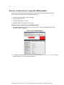
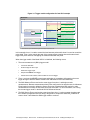
Exercise: Retrieve readings from a buffer
To retrieve readings from a populated buffer:
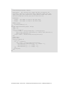
1. From the navigation area on the left side of the web interface, select Reading Buffers. The
Reading Buffers embedded page is displayed.
Figure 6: Select reading buffer
2. Select smua.nvbuffer1 (1).
3. In the Recall Attributes area (near the bottom of the page), select Values and Time Stamp (2).
4. Click Download (3). The table displays the present buffer data.
Test Equipment Depot - 800.517.8431 - 99 Washington Street Melrose, MA 02176 - TestEquipmentDepot.com
Figure 7: Downloading the reading buffer
1
2
3
5. Notice that the Source Value column is not populated. To collect source values, before taking
readings, use TSB Embedded to set the following attribute:
smua.nvbuffer1.collectsourcevalues = 1.
Figure 8: Sample downloaded reading buffer
TSP Express
The TSP® Express tab provides access to the TSP Express Launch page. From this page, click the
Launch button to start TSP Express.
Test Equipment Depot - 800.517.8431 - 99 Washington Street Melrose, MA 02176 - TestEquipmentDepot.com
NOTE
Only one TSB Embedded or TSP Express session can be running and connected to the same
instrument.
Figure 9: Select TSP Express
To run TSP Express:
1. From the navigation area on the left side of the web interface, select TSP Express. The TSP
Express page is displayed.
2. Click the Launch button. The TSP Express window opens.
3. There is a help pane on the right side of the main window. You can adjust the width of the help
pane by sliding the vertical bar. Click and follow the step-by-step example to become familiar with
TSP Express (there is a link to the example in the TSP Express Introduction's first paragraph).
Test Equipment Depot - 800.517.8431 - 99 Washington Street Melrose, MA 02176 - TestEquipmentDepot.com
Section 3: Using the web interface
Model 2651A High Power System SourceMeter® Instrument User's Manual
Figure 10: TSP Express
3-10
2651A-900-01 Rev. A / March 2011
Test Equipment Depot - 800.517.8431 - 99 Washington Street Melrose, MA 02176 - TestEquipmentDepot.com
Section 4
Making basic front-panel measurements
In this section:
Introduction .............................................................................. 4-1
Equipment needed for this example......................................... 4-1
Device connections .................................................................. 4-1
Making front-panel measurements........................................... 4-2
Introduction
You can use the Model 2651A High Power System SourceMeter® Instrument to make basic
measurements from the front panel. In this example, measurements are made on a 10 kΩ resistor.
Similar measurements can be made on any two-terminal device under test (DUT) if appropriate
source values are used.
Equipment needed for this example
To run this example, you will need the following equipment:
•
Model 2651A High Power System SourceMeter® Instrument
•
Additional cable and connector assemblies as required to make connections to the DUT (for
example, Model 2651A-KIT). See Device connections (on page 4-1) for a schematic of required
connections.
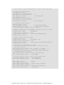
Device connections
Connections from the Model 2651A High Power System SourceMeter® Instrument to the DUT are
shown in the diagram below. Proper care should be taken to ensure good contact through all
connections.
Figure 11: Two-wire resistance connections
SENSE/GUARD
S
LO G
S
G G G HI
OUTPUT
LO
HI
40V, 50A MAX.
HI
DUT
LO
Test Equipment Depot - 800.517.8431 - 99 Washington Street Melrose, MA 02176 - TestEquipmentDepot.com
Making front-panel measurements
Use the following procedure to configure the instrument and make measurements from the front
panel.
Step 1: Select and set source level
Perform the following steps to select the voltage source and set its value to 10 V:
1. Press the SRC key as needed to select the V-Source, as indicated by the units in the source field
on the display. The flashing digit (cursor) indicates which value is selected for editing.
2. Move the cursor to the digit to change, then press the navigation wheel
mode, as indicated by the EDIT indicator.
to enter the EDIT
3. Use the RANGE keys to select the 10 V range. If using a different source value, use the lowest
possible range for the best accuracy.
4. Set the source value to 10.0000 V, and then press the ENTER key or the navigation wheel
complete editing.
to
Step 2: Set compliance limit
Perform the following steps to edit the compliance limit value to 10 mA:
1. Press the LIMIT key.
2. Move the cursor to the digit to change, then press the navigation wheel
mode, as indicated by the EDIT indicator.
to enter the EDIT
3. Enter the limit value of 10.000 mA.
4. Press the ENTER key or the navigation wheel
to complete editing.
Step 3: Select measurement function and range
To select measurement function and range:
1. Select the current measurement function by pressing the MEAS key as needed.
2. Enable autorange by pressing the AUTO key (the AUTO indicator lights). Alternatively, you can
set manual ranging using the up or down RANGE keys.
Step 4: Turn output on
Turn the output on by pressing the OUTPUT ON/OFF control. The OUTPUT indicator light turns on.
Test Equipment Depot - 800.517.8431 - 99 Washington Street Melrose, MA 02176 - TestEquipmentDepot.com
Model 2651A High Power System SourceMeter® Instrument User's Manual Section 4: Making basic front-panel measurements
Step 5: Observe readings on the display
1. Observe the readings on the display. Press the TRIG key if necessary to trigger the instrument to
begin taking readings. The readings are on the top line, and source and limit values are on the
bottom line. For the 10 kΩ resistor, typical display values are:
1.00000mA
SrcA: +10.0000 V LimA:010.0000mA
2. Press the MEAS key several times to display measured voltage, resistance, power, and current.
Typical values for the 10 kΩ resistor are:
10.0000 V, 10.0000 kΩ, 10.0000 mW, and 1.00000 mA
Step 6: Turn output off
When finished, turn the output off by pressing the OUTPUT ON/OFF control. The OUTPUT indicator
light will turn off.
2651A-900-01 Rev. A / March 2011
Test Equipment Depot - 800.517.8431 - 99 Washington Street Melrose, MA 02176 - TestEquipmentDepot.com
4-3
Section 5
Capturing high power pulse waveforms
In this section:
Introduction to capturing waveforms ........................................ 5-1
Equipment needed for this example......................................... 5-1
Set up communication.............................................................. 5-1
Device connections .................................................................. 5-2
Configuring the trigger model ................................................... 5-2
Example program code ............................................................ 5-4
Example program usage .......................................................... 5-9
Introduction to capturing waveforms
The Model 2651A High Power System SourceMeter® Instrument offers a unique feature. In addition to
a traditional integrating ADC, the Model 2651A also features a fast-sampling ADC. The fast ADC of
the Model 2651A allows the instrument to take measurements at high speed, with capabilities similar
to an oscilloscope. This allows you to capture data at up to one million samples per second with more
than 5000 readings in a single burst. This feature allows simultaneous current and voltage
measurements without any additional hardware, and offers 18-bit resolution providing for high
accuracy, even at high speed. The fast ADC of the Model 2651A allows this instrument to be used in
a broad range of applications, such as negative bias temperature instability (NBTI) testing and
transient thermal analysis.
In this example, we will demonstrate how to use the fast ADC of the Model 2651A to capture both the
current and voltage waveforms of high power pulses.
Equipment needed for this example
To run this test, you will need the following equipment:
•
Model 2651A High Power System SourceMeter® Instrument
•
GPIB cable or Ethernet cable to connect the Model 2651A to a computer
•
Additional cable and connector assemblies as required to make connections to the device under
test (DUT) (for example, Model 2651A-KIT); see Device connections (on page 5-2) for a
schematic of required connections
Set up communication
The communication setup is illustrated in the following diagram. GPIB is used as an example, but this
application can be run using any of the supported communication interfaces for the instrument.
Test Equipment Depot - 800.517.8431 - 99 Washington Street Melrose, MA 02176 - TestEquipmentDepot.com
Figure 12: GPIB communication example for fast ADC
PU
ARM
9
LIMIT
5
1
LOAD
2
RUN
R
TE
N
8
MEAS
4
TO E D IT / E
7
SRC
DIGITS SPEED
CONFIG
NF
2651A HIGH POWER SYSTEM SourceMeter ®
N
SH
DISPLAY
TO EDIT / E
PU
SrcA:+20.0000 A LimAL10.0000V
POWER
SH
R
+3.21000V
TE
GPIB
+/MODE
6
0
REL
FILTER
3
0000
STORE RECALL
AUTO
OU
TPUT
ON
/ OFF
CURSOR
LOCAL
TRIG
MENU
EXIT
ENTER
Controller
Device connections
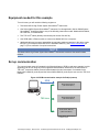
Make the connections as illustrated in the following figure. To ensure good contact, use care when
making connections.
Figure 13: Connections for fast ADC example
Model 2651A
OUTPUT
SENSE/GUARD
S
LO G
LO
S
G G G HI
HI
LO
40V, 50A MAX.
HI
S HI
LED
(DUT)
S LO
Equivalent
HI
S HI
SMU
LED
(DUT)
LO
S LO
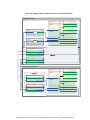
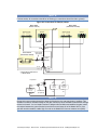
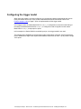
Configuring the trigger model
To output precisely timed high power pulses and accurately capture the pulse with the fast ADC, the
trigger model of the Model 2651A High Power System SourceMeter® Instrument must be used. Using
the trigger model, we can output pulses as large as 50 A with pulse widths as small as 100 μs and
position our measurements with microsecond resolution. The image below is a diagram of the trigger
model used in this example.
Test Equipment Depot - 800.517.8431 - 99 Washington Street Melrose, MA 02176 - TestEquipmentDepot.com
Figure 14: Trigger model configuration for fast ADC example
Model 2651A
Local node*
smua.trigger.
IDLE_EVENT_ID
Idle
Arm layer
SWEEPING_EVENT_ID
arm.count = 1
arm.stimulus
SWEEP_COMPLETE_EVENT_ID
trigger.timer[1].
stimulus
EVENT_ID
0.03 s
passthrough = true
Trigger layer
ARMED_EVENT_ID
count = 4
count = 5
source.stimulus
SOURCE_COMPLETE_EVENT_ID
measure.stimulus
trigger.timer[2].
stimulus
EVENT_ID
3 ms
passthrough = false
MEASURE_COMPLETE_EVENT_ID
endpulse.stimulus
PULSE_COMPLETE_EVENT_ID
count = 1
* Local node: Since only one instrument is being used in this example, the local node is used.
In this example, timer 1 is used to control the time between pulses while timer 2 is used to control the
pulse width. Timer 1 also controls the start of the measurements, starting them at the same time it
triggers the pulse and thus overlapping the measurements with the pulse.
When the trigger model of the Model 2651A is initialized, the following occurs:
1. The source-measure unit (SMU) trigger model:
•
Leaves the idle state
•
Flows through the Arm Layer
•
Enters the Trigger Layer
•
Outputs the ARMED event trigger
•
Pauses at the Source Event, where it waits for an event trigger
2. Timer 1 receives the ARMED event trigger and begins its countdown while passing the event
trigger through to both the SMU's Source Event and Measure Event simultaneously.
3. The SMU Measure Event receives the event trigger from timer 1 and begins to take
measurements. Because measurements have been configured to be asynchronous, the Measure
Event begins its execution before the Source Event has completed and will continue to take
measurements even after the End Pulse Event has executed. For more information, see "Using
the remote trigger model" in the Model 2651A Reference Manual.
4. The SMU Source Event receives the event trigger from timer 1, begins to output the pulse, and
then waits the programmed source delay (if any) before it outputs the SOURCE_COMPLETE
event to timer 2 and allows the SMU trigger model to continue.
Test Equipment Depot - 800.517.8431 - 99 Washington Street Melrose, MA 02176 - TestEquipmentDepot.com
5. Timer 2 receives the SOURCE_COMPLETE_EVENT_ID event trigger from timer 1 and begins its
countdown.
6. The SMU trigger model continues to the End Pulse Event, where it pauses and waits for an event
trigger from timer 2.
7. The timer 2 countdown expires and timer 2 outputs an event trigger to the SMU End Pulse Event.
8. The SMU End Pulse Event receives the event trigger from timer 2 and outputs the falling edge of
the pulse, after which it allows the SMU trigger model to continue.
9. The SMU trigger model then compares the current Trigger Layer loop iteration with the trigger
count:
•
If the current iteration is less than the trigger count, the Trigger Layer repeats and the SMU trigger
model reaches Source Event, where it waits for another trigger from timer 1. The trigger model then
repeats from step 3.
•
If the current iteration is equal to the trigger count, the SMU trigger model exits the Trigger Layer,
passes through the Arm Layer, and returns to idle.
Example program code
NOTE
The example code is designed to be run from Test Script Builder or TSB Embedded. It can also be
run from other programming environments, such as Microsoft® Visual Studio® or National Instruments
LabVIEWTM. However, modification of the example code may be required to do so.
The following script contains all the code necessary to output and capture a current or voltage pulse
using the Model 2651A fast ADC. The script sets up the source-measure unit (SMU), configures the
trigger model, prepares the reading buffers, executes the test, and outputs the collected data in a
format that can be copied and pasted from the instrument console to a Microsoft® Excel®
spreadsheet.
The script is written using Test Script Processor (TSP®) functions rather than as a single block of
inline code. TSP functions are similar to functions in other programming languages, such as
Microsoft® Visual C® or Visual Basic®, and must be called before the code contained in them is
executed. Because of this, running the script alone will not execute the test. To execute the test, run
the script to load the functions into test script memory and then call the functions. Refer to the
documentation for Test Script Builder or TSB Embedded (on page 3-3) for directions on how to run
scripts and enter commands using the instrument console.
The script contains comments that describe what is being performed by the lines of code and
documentation for the functions in the script.
--[[
Title:
Fast ADC Usage
Description: This script is designed to output pulses and capture
both the current and the voltage of the pulse using the fast ADC of
the Model 2651A High Power System SourceMeter instrument.
Equipment Needed:
1x 2651A
]]
Test Equipment Depot - 800.517.8431 - 99 Washington Street Melrose, MA 02176 - TestEquipmentDepot.com
--[[
Name: CapturePulseV(pulseLevel, pulseWidth, pulseLimit, numPulses)
Description:
This function outputs voltage pulses with a 1% duty cycle and
performs measurements using the fast ADC to capture each pulse in
its entirety. At the conclusion of the pulse train, the data is
returned to the instrument console in a Microsoft Excel compatible format.
Parameters:
pulseLevel:
pulseWidth:
pulseLimit:
numPulses:
The voltage level of the pulse in volts
The width of the pulse in seconds
100e-6 <= pulseWidth <= 4e-3
The current limit of the pulse in amps
The number of pulses to output
Example Usage:
CapturePulseV(5, 300e-6, 50, 5)
]]
function CapturePulseV(pulseLevel, pulseWidth, pulseLimit, numPulses)
if (numPulses == nil) then numPulses = 1 end
-- Configure the SMU
reset()
smua.reset()
smua.source.func
smua.sense
smua.source.rangev
smua.source.levelv
smua.source.limiti
=
=
=
=
=
smua.OUTPUT_DCVOLTS
smua.SENSE_REMOTE
pulseLevel
0
-- The bias level
5
-- The DC limit
-- Use a measure range that is as large as the biggest
-- possible pulse
smua.measure.rangei
= pulseLimit
smua.measure.rangev
= pulseLevel
-- Select the fast ADC for measurements
smua.measure.adc
= smua.ADC_FAST
-- Set the measure count to be 1.25 times the width of the pulse
-- to ensure we capture the entire pulse plus falling edge.
smua.measure.count
= (pulseWidth / smua.measure.interval) * 1.25
-- Prepare the reading buffers
smua.nvbuffer1.clear()
smua.nvbuffer1.collecttimestamps
=
smua.nvbuffer1.collectsourcevalues
=
smua.nvbuffer1.fillmode
=
smua.nvbuffer2.clear()
smua.nvbuffer2.collecttimestamps
=
smua.nvbuffer2.collectsourcevalues
=
smua.nvbuffer2.fillmode
=
-- Cannot use source values with async
1
0
smua.FILL_ONCE
1
0
smua.FILL_ONCE
measurements
Test Equipment Depot - 800.517.8431 - 99 Washington Street Melrose, MA 02176 - TestEquipmentDepot.com
-- Configure the Pulsed Sweep setup
------------------------------------ Timer 1 controls the pulse period
trigger.timer[1].count
= numPulses - 1
-- -- 1% Duty Cycle
trigger.timer[1].delay
= pulseWidth / 0.01
trigger.timer[1].passthrough = true
trigger.timer[1].stimulus
= smua.trigger.ARMED_EVENT_ID
-- Timer 2 controls the pulse
trigger.timer[2].count
trigger.timer[2].delay
trigger.timer[2].passthrough
trigger.timer[2].stimulus
width
= 1
= pulseWidth - 3e-6
= false
= smua.trigger.SOURCE_COMPLETE_EVENT_ID
-- Configure SMU Trigger Model for Sweep/Pulse Output
------------------------------------------------------ Pulses will all be the same level so set start and stop to
-- the same value and the number of points in the sweep to 2
smua.trigger.source.linearv(pulseLevel, pulseLevel, 2)
smua.trigger.source.limiti
= pulseLimit
smua.trigger.measure.action
= smua.ASYNC
-- We want to start the measurements before the source action takes
-- place, so we must configure the ADC to operate asynchronously of
-- the rest of the SMU trigger model actions
-- Measure I and V during the pulse
smua.trigger.measure.iv(smua.nvbuffer1, smua.nvbuffer2)
-- Return the output to the bias
smua.trigger.endpulse.action
=
smua.trigger.endsweep.action
=
smua.trigger.count
=
smua.trigger.arm.stimulus
=
smua.trigger.source.stimulus
=
smua.trigger.measure.stimulus =
smua.trigger.endpulse.stimulus =
smua.trigger.source.action
=
smua.source.output
smua.trigger.initiate()
waitcomplete()
smua.source.output
level at the end of the pulse/sweep
smua.SOURCE_IDLE
smua.SOURCE_IDLE
numPulses
0
trigger.timer[1].EVENT_ID
trigger.timer[1].EVENT_ID
trigger.timer[2].EVENT_ID
smua.ENABLE
= smua.OUTPUT_ON
= smua.OUTPUT_OFF
PrintPulseData()
end
Test Equipment Depot - 800.517.8431 - 99 Washington Street Melrose, MA 02176 - TestEquipmentDepot.com
--[[
Name:
CapturePulseI(pulseLevel, pulseWidth, pulseLimit,
numPulses)
Description:
This function outputs current pulses with a 1% duty cycle and performs
measurements using the fast ADC to capture each pulse in its entirety.
At the conclusion of the pulse train, the data is returned to the
instrument console in a Microsoft Excel compatible format.
Parameters:
pulseLevel:
pulseWidth:
pulseLimit:
numPulses:
The current level of the pulse in amps
The width of the pulse in seconds
100e-6 <= pulseWidth <= 4e-3
The voltage limit of the pulse in volts
The number of pulses to output
Example Usage:
CapturePulseI(50, 300e-6, 10, 5)
]]
function CapturePulseI(pulseLevel, pulseWidth, pulseLimit, numPulses)
if (numPulses == nil) then
numPulses = 1
end
-- Configure the SMU
reset()
smua.reset()
smua.source.func
smua.sense
smua.source.rangei
smua.source.leveli
smua.source.limitv
=
=
=
=
=
smua.OUTPUT_DCAMPS
smua.SENSE_REMOTE
pulseLevel
0
-- The bias level
10
-- The DC limit
-- Use a measure range that is as large as the biggest possible pulse.
smua.measure.rangev
= pulseLimit
smua.measure.rangei
= pulseLevel
-- Select the fast ADC for measurements
smua.measure.adc
= smua.ADC_FAST
-- Set the measure count to be 1.25 times the width of the pulse
-- to ensure we capture the entire pulse plus falling edge.
smua.measure.count
= pulseWidth / smua.measure.interval) * 1.25
-- Prepare the reading buffers
smua.nvbuffer1.clear()
smua.nvbuffer1.collecttimestamps
=
smua.nvbuffer1.collectsourcevalues
=
smua.nvbuffer1.fillmode
=
smua.nvbuffer2.clear()
smua.nvbuffer2.collecttimestamps
=
smua.nvbuffer2.collectsourcevalues
=
smua.nvbuffer2.fillmode
=
-- Cannot use source values with async
1
0
smua.FILL_ONCE
1
0
smua.FILL_ONCE
measurements
Test Equipment Depot - 800.517.8431 - 99 Washington Street Melrose, MA 02176 - TestEquipmentDepot.com
-- Configure the Pulsed Sweep setup
------------------------------------ Timer 1 controls the pulse period
trigger.timer[1].count
= numPulses - 1
-- 1% Duty Cycle
trigger.timer[1].delay
= pulseWidth / 0.01
trigger.timer[1].passthrough = true
trigger.timer[1].stimulus
= smua.trigger.ARMED_EVENT_ID
-- Timer 2 controls the pulse
trigger.timer[2].count
trigger.timer[2].delay
trigger.timer[2].passthrough
trigger.timer[2].stimulus
width
= 1
= pulseWidth - 3e-6
= false
= smua.trigger.SOURCE_COMPLETE_EVENT_ID
-- Configure SMU Trigger Model for Sweep/Pulse Output
------------------------------------------------------ Pulses will all be the same level so set start and stop to
-- the same value and the number of points in the sweep to 2
smua.trigger.source.lineari(pulseLevel, pulseLevel, 2)
smua.trigger.source.limitv
= pulseLimit
smua.trigger.measure.action
= smua.ASYNC
-- We want to start the measurements before the source action takes
-- place, so we must configure the ADC to operate asynchronously of
-- the rest of the SMU trigger model actions
-- Measure I and V during the pulse
smua.trigger.measure.iv(smua.nvbuffer1, smua.nvbuffer2)
-- Return the output to the bias
smua.trigger.endpulse.action
=
smua.trigger.endsweep.action
=
smua.trigger.count
=
smua.trigger.arm.stimulus
=
smua.trigger.source.stimulus
=
smua.trigger.measure.stimulus =
smua.trigger.endpulse.stimulus =
smua.trigger.source.action
=
smua.source.output
smua.trigger.initiate()
waitcomplete()
smua.source.output
level at the end of the pulse
smua.SOURCE_IDLE
smua.SOURCE_IDLE
numPulses
0
trigger.timer[1].EVENT_ID
trigger.timer[1].EVENT_ID
trigger.timer[2].EVENT_ID
smua.ENABLE
= smua.OUTPUT_ON
= smua.OUTPUT_OFF
PrintPulseData()
end
Test Equipment Depot - 800.517.8431 - 99 Washington Street Melrose, MA 02176 - TestEquipmentDepot.com
--[[
Name: PrintPulseData()
Description;
This function prints the data contained in smua.nvbuffer1 and
smua.nvbuffer2 in a format that is copy and paste compatible with
Microsoft Excel.
]]
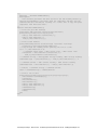
function PrintPulseData()
print("Timestamp\tVoltage\tCurrent")
for i=1, smua.nvbuffer1.n do
print(string.format("%g\t%g\t%g", smua.nvbuffer1.timestamps[i],
smua.nvbuffer2[i], smua.nvbuffer1[i]))
end
end
Example program usage
The functions in this script allow the parameters of the test to be adjusted without rewriting and
rerunning the script. To execute the test, either call CapturePulseV() (to capture voltage) or
CapturePulseI() (to capture current), passing in the appropriate values as parameters.
The parameters of the CapturePulseV() function are in the following table:
CapturePulseV() parameters
Parameter
pulseLevel
pulseWidth
pulseLimit
numPulses
Units
Description
Volts
The voltage level of the pulse
Seconds
The width of the pulse
Amperes
The current limit of the pulses to output
Not applicable
The number of pulses to output
An example call to this function is as follows:
CapturePulseV(10, 300e-6, 50, 5)
This call will output five 10 V pulses with a 300 μs pulse width. The pulses will be limited to 50 A and
have a 1 percent duty cycle. At the completion of the pulsed outputs, the source-measure unit (SMU)
output is turned off. The resulting data from this test will be returned in a Microsoft® Excel® compatible
format (you can cut and paste the output from the console) that can be used for graphing and
analysis.
The parameters of the CapturePulseI() function are contained in the following table:
CapturePulseI() parameters
Parameter
Units
Description
pulseLevel
Amperes
The current level of the pulse
pulseWidth
Seconds
The width of the pulse
pulseLimit
Volts
The voltage limit of the pulses to output
numPulses
Not applicable
The number of pulses to output
Test Equipment Depot - 800.517.8431 - 99 Washington Street Melrose, MA 02176 - TestEquipmentDepot.com
Section 5: Capturing high power pulse waveforms Model 2651A High Power System SourceMeter® Instrument User's Manual
An example call to this function is as follows:
CapturePulseI(50, 300e-6, 50, 5)
This call will output five 50 A pulses with a 300 μs pulse width. The pulses will be limited to 10 V and
have a 1% duty cycle. At the completion of the pulsed outputs, the SMU output is turned off. The
resulting data from this test will be returned in a Microsoft® Excel® compatible format (you can cut and
paste the output from the console) that can be used for graphing and analysis.
5-10
2651A-900-01 Rev. A / March 2011
Test Equipment Depot - 800.517.8431 - 99 Washington Street Melrose, MA 02176 - TestEquipmentDepot.com
Section 6
Characterization of power discretes
In this section:
Introduction to power discrete I-V curve testing ....................... 6-1
Equipment needed for this example......................................... 6-2
Set up communication.............................................................. 6-2
Device connections .................................................................. 6-4
Configuring the trigger model ................................................... 6-5
Example program code .......................................................... 6-10
Example program usage ........................................................ 6-16
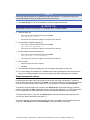
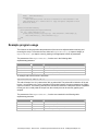
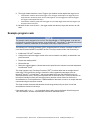
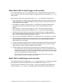
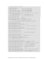
Introduction to power discrete I-V curve testing
A common test performed on power MOSFETs and IGBTs characterizes the I-V performance of the
device under test (DUT) at various gate voltages. In this test, the gate of the device is held at a
constant voltage while the voltage on the drain (or collector) of the device is swept and current is
measured. This process is repeated for several different gate voltages, and the resulting data is
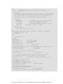
plotted to show a series of I-V curves for the device. The following figure illustrates an example of this
plot for a power MOSFET device.
Figure 15: Example set of IV curves for a power MOSFET device
50
45
40
Ids (amperes)
35
30
Vgs = 5.00
Vgs = 6.00
Vgs = 7.00
Vgs = 8.00
Vgs = 9.00
25
20
15
10
5
0
0
2
4
6
8
10
12
Vds (volts)
Test Equipment Depot - 800.517.8431 - 99 Washington Street Melrose, MA 02176 - TestEquipmentDepot.com
To avoid device self-heating, this test is usually performed using pulsed measurements. This method
pulses voltage across the device for a short duration. During this pulse, after the pulse has settled,
the current is measured. The duration of the pulse and the duty cycle in which the pulses are applied
to the device are controlled, minimizing self-heating. A single Model 2651A High Power System
SourceMeter® Instrument can pulse-measurement test with precision timing at currents up to 50 A
and pulse widths as low as 100 µs.
This example demonstrates how to perform pulsed measurements and collect I-V curves using the
Model 2651A High Power System SourceMeter® Instrument on a MOSFET. The same procedure
could be used to test IGBTs.
Equipment needed for this example
To run this test, you will need the following equipment:
•
Model 2651A High Power System SourceMeter® Instrument
•
Series 2600A System SourceMeter® Instrument (see NOTE)
•
TSP-Link® cable (Keithley Instruments part number CA-180-3A)
•
GPIB cable or Ethernet cable to connect the Model 2651A to a computer
•
Additional cable and connector assemblies as required to make connections to the device under
test (DUT) (for example, Model 2651A-KIT and Model 2600-KIT); see Device connections (on
page 6-4) for a schematic of required connections
NOTE
For this application, Series 2600A System SourceMeter® Instrument refers to any of the following
instrument models: Models 2601A/2602A, 2611A/2612A, or 2635A/2636A.
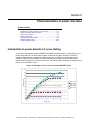
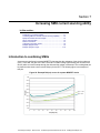
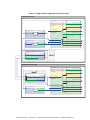
Set up communication
The communication setup is illustrated in the following diagram. GPIB is used as an example, but this
application can be run using any of the supported communication interfaces for the instruments. A
TSP-Link® connection enables communication between the two instruments. Commands for the
Series 2600A (on TSP-Link node 2) are sent over the TSP-Link interface.
Test Equipment Depot - 800.517.8431 - 99 Washington Street Melrose, MA 02176 - TestEquipmentDepot.com
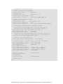
Figure 16: GPIB communication overview
GPIB
Model 2651A
(TSP-Link Node #1)
TSP-Link
Controller
Series 26xxA*
(TSP-Link Node #2)
* Model 260xA, Model 261xA,
or Model 263xA
When using the TSP-Link communication interface, each instrument must have a unique TSP-Link
node number. Configure the node number for the:
•
Model 2651A to 1
•
Series 2600A to 2
To set the TSP-Link node number using the front-panel interface:
1. Press the MENU key.
2. Select TSPLink.
3. Select NODE.
4. Use the navigation wheel
to adjust the node number.
5. Press the ENTER key to save the TSP-Link node number.
On the Model 2651A SMU #1 (TSP-Link node #1), perform a TSP-Link reset to update it with the
linked instruments:
1. Press the MENU key.
2. Select TSPLink.
3. Select RESET.
NOTE
If error 1205 is generated during the TSP-link reset, ensure that the Series 2600A has a unique
TSP-Link node number.
Quick Tip
You can also perform a TSP-Link reset from the remote command interface by sending
tsplink.reset() to the Model 2651A. This method is used in the example program.
Test Equipment Depot - 800.517.8431 - 99 Washington Street Melrose, MA 02176 - TestEquipmentDepot.com
Device connections
To run the test, make the connections as illustrated in the following figure. To ensure good contact,
use care when making connections.
NOTE
For best results, all connections should be left floating (no connections should be tied to ground).
Figure 17: Connections for IV curve characterization
Model 2651A
(master node #1)
LO
S
G G G HI
D
G
OUTPUT
SENSE/GUARD
S
LO G
Equivalent
HI
HI
S HI
40V, 50A MAX.
HI
S HI
SMU
SMU
(subordinate
node #2)
(master
node #1)
LO
S LO
LO
S
Gate resistor
(if required)
LO
S LO
HI
S HI
Series 26xxA*
(subordinate node #2)
D
G
LO S G HI G G G S
LO
HI
N-Channel
power
MOSFET
S
Gate resistor
(if required)
S LO
LO
S LO
LO
* Model 260xA, Model 261xA,
or Model 263xA
NOTE
During high-current pulsing through the channel of the device, the gate may begin to oscillate. This
oscillation creates an unstable voltage on the gate, which may cause unstable measurements through
the device channel. You can install a resistor to dampen this oscillation and stabilize the gate. Install
the resistor between the gate of the device and the force and sense HI of the Model 2651A. If the
gate still remains unstable, enable High-C mode on the Model 2651A source-measure unit (SMU).
Test Equipment Depot - 800.517.8431 - 99 Washington Street Melrose, MA 02176 - TestEquipmentDepot.com
Configuring the trigger model
Correctly configuring the trigger model allows you to achieve pulsed measurements with precise
timing and current levels up to 50 A on the Model 2651A. The following figure illustrates this test's
overall trigger model configuration, including the interactions between the Model 2651A and the
Series 2600A instrument. Refer to the Example program code (on page 6-10) for an implementation
of this trigger model.
In this example, the trigger model of each instrument is configured to perform a linear sweep.
The Series 2600A is configured to sweep the voltage applied to the gate of the device.
The Model 2651A is configured to sweep the voltage across the drain (or collector) of the device. The
Model 2651A is configured to repeat its sweep and will do so as many times as there are steps in the
sweep of the Series 2600A.
For example, if the Model 2651A instrument’s sweep contains four points and the Series 2600A
instrument’s sweep contains three points, the Model 2651A instrument’s sweep will run three times,
for a total of 12 points. To synchronize the sweeps between instruments, the trigger lines of the TSPLink® interface are used. The following figure illustrates the 12-point sweep example.
Figure 18: SMU output from configured trigger model
4V
Gate
(Series 26xxA)
0V
4V
Drain
or Collector
(Model 2651A)
0V
Test Equipment Depot - 800.517.8431 - 99 Washington Street Melrose, MA 02176 - TestEquipmentDepot.com
Figure 19: Trigger model configuration for IV curve characterization
Model 2651A (master)
node[1].
smua.trigger.
IDLE_EVENT_ID
Idle
Arm layer
SWEEPING_EVENT_ID
arm.count = 5
arm.stimulus
SWEEP_COMPLETE_EVENT_ID
trigger.timer[1].
stimulus
EVENT_ID
0.03 s
passthrough = true
Trigger layer
ARMED_EVENT_ID
count = 20
count = 21
source.stimulus
SOURCE_COMPLETE_EVENT_ID
measure.stimulus
trigger.timer[2].
stimulus
EVENT_ID
0.001 s
passthrough = false
MEASURE_COMPLETE_EVENT_ID
endpulse.stimulus
PULSE_COMPLETE_EVENT_ID
count = 1
tsplink.trigger[1].
EVENT_ID
mode = tsplink.TRIG_SYNCHRONOUSM
stimulus
tsplink.trigger[2].
EVENT_ID
mode = tsplink.TRIG_FALLING
stimulus
Series 26xxA (subordinate)*
node[2].
smua.trigger.
IDLE_EVENT_ID
Idle
Arm layer
tsplink.trigger[1].
SWEEPING_EVENT_ID
arm.count = 1
EVENT_ID
mode = tsplink.TRIG_SYNCHRONOUSA
arm.stimulus
SWEEP_COMPLETE_EVENT_ID
Trigger layer
ARMED_EVENT_ID
stimulus
count = 5
source.stimulus
tsplink.trigger[2].
SOURCE_COMPLETE_EVENT_ID
EVENT_ID
measure.stimulus
MEASURE_COMPLETE_EVENT_ID
mode = tsplink.TRIG_FALLING
endpulse.stimulus
stimulus
PULSE_COMPLETE_EVENT_ID
* Model 260xA, Model 261xA, or Model 263xA
Test Equipment Depot - 800.517.8431 - 99 Washington Street Melrose, MA 02176 - TestEquipmentDepot.com
Model 2651A trigger model operation
The following figure illustrates this test's Model 2651A trigger model configuration.
Figure 20: Model 2651A trigger model for IV curve characterization
Model 2651A (master)
node[1].
smua.trigger.
IDLE_EVENT_ID
Idle
Arm layer
SWEEPING_EVENT_ID
arm.count = 5
arm.stimulus
SWEEP_COMPLETE_EVENT_ID
trigger.timer[1].
stimulus
EVENT_ID
0.03 s
passthrough = true
Trigger layer
ARMED_EVENT_ID
count = 20
count = 21
source.stimulus
SOURCE_COMPLETE_EVENT_ID
measure.stimulus
trigger.timer[2].
stimulus
EVENT_ID
0.001 s
passthrough = false
MEASURE_COMPLETE_EVENT_ID
endpulse.stimulus
PULSE_COMPLETE_EVENT_ID
count = 1
tsplink.trigger[1].
EVENT_ID
mode = tsplink.TRIG_SYNCHRONOUSM
stimulus
tsplink.trigger[2].
EVENT_ID
mode = tsplink.TRIG_FALLING
stimulus
TSP-Link bus
Test Equipment Depot - 800.517.8431 - 99 Washington Street Melrose, MA 02176 - TestEquipmentDepot.com
When the configured trigger model of the Model 2651A is initiated, the following occurs:
1. The source-measure unit (SMU) trigger model passes through the Arm Layer, enters the Trigger
Layer, then outputs the ARMED event trigger.
2. The ARMED event trigger triggers TSP-Link® trigger 1, which outputs a trigger on TSP-Link line 1.
This trigger is meant to tell the Series 2600A that it should step the gate SMU.
3. The SMU trigger model continues until it reaches the Source Event and then pauses and waits for
an event trigger.
4. A trigger comes back on TSP-Link trigger 1, indicating that the gate step is complete. An event
trigger is output from TSP-Link trigger 1 and input to timer 1.
5. Timer 1 receives the event trigger and begins its countdown while simultaneously passing the
event trigger.
6. The SMU Source Event Detector receives the event trigger from timer 1, sets the SMU output to
the pulse level, waits for a programmed source delay (if any), and outputs the
SOURCE_COMPLETE event to timer 2.
7. Timer 2 receives the SOURCE_COMPLETE event trigger and begins its countdown.
8. The SMU trigger model moves to the Measure Event, where it waits for a programmed measure
delay (if any), then takes a measurement.
9. The SMU trigger model moves to the End Pulse Event, where it stops and waits for an event
trigger from timer 2.
10. The timer 2 countdown expires and outputs an event trigger to the SMU End Pulse Event.
11. The End Pulse Event Detector receives the event trigger from timer 2, sets the SMU output to the
bias level, and then continues.
12. The trigger model checks the current Trigger Layer iteration number against the trigger count.
•
If the iteration number is less than the trigger count, the trigger model stays in the trigger layer and
wraps around to the Source Event, where it waits again for an event trigger from timer 1 (as it did in step
3). This time, however, timer 2 will not receive an event trigger from TSP-Link trigger 1. Despite this, the
trigger model will continue running because the timer 1 count was set to one less than the trigger count.
Therefore, timer 1 will continue outputting event triggers while the trigger model is in the Trigger Layer,
outputting one trigger event every time the countdown expires. The trigger model continues as
described in step 6.
•
If the iteration number is greater than the trigger count, the SMU trigger model exits the Trigger Layer
and goes into the Arm Layer.
13. Upon entering the Arm Layer, the SMU trigger model outputs the SWEEP_COMPLETE event
trigger.
14. TSP-Link trigger 2 receives the SWEEP_COMPLETE event trigger and outputs a trigger on TSPLink line 2. This trigger is meant to signal the Series 2600A that it is acceptable to continue, and it
no longer needs to hold the current gate level.
15. The trigger model checks the current Arm Layer iteration number against the arm count.
•
If the iteration number is less than the arm count, the trigger model stays in the Arm Layer and begins
the entire process again from step 1.
•
If the iteration number is greater than the arm count, the trigger model continues, exits the Arm Layer,
and returns to an iIdle state.
Test Equipment Depot - 800.517.8431 - 99 Washington Street Melrose, MA 02176 - TestEquipmentDepot.com
Series 26xxA instrument's trigger model operation
The following figure illustrates the Series 26xxA trigger model configuration for this test.
Figure 21: Series 26xxA instrument's trigger model for IV curve characterization
TSP-Link bus
Series 26xxA (subordinate)*
node[2].
smua.trigger.
IDLE_EVENT_ID
Idle
Arm layer
tsplink.trigger[1].
SWEEPING_EVENT_ID
arm.count = 1
EVENT_ID
mode = tsplink.TRIG_SYNCHRONOUSA
arm.stimulus
SWEEP_COMPLETE_EVENT_ID
Trigger layer
ARMED_EVENT_ID
stimulus
count = 5
source.stimulus
tsplink.trigger[2].
SOURCE_COMPLETE_EVENT_ID
EVENT_ID
measure.stimulus
MEASURE_COMPLETE_EVENT_ID
mode = tsplink.TRIG_FALLING
endpulse.stimulus
stimulus
PULSE_COMPLETE_EVENT_ID
* Model 260xA, Model 261xA, or Model 263xA
When the configured trigger model of the Series 2600A instrument is initiated, the following occurs:
1. The source-measure unit (SMU) trigger model passes through the Arm Layer, enters the Trigger
Layer, reaches the Source Event, pauses, and then waits for an event trigger from TSP-Link®
trigger 1.
2. A TSP-Link trigger is received by TSP-Link trigger 1. Because TSP-Link trigger 1 is configured as
a synchronous acceptor, it latches the line low and outputs an event trigger to the SMU Source
Event.
3. The SMU Source Event Detector receives the event trigger from TSP-Link trigger 1, sets the
SMU output to the step level, waits a programmed source delay (if any) and continues.
4. The SMU trigger model moves to the Measure Event, where it waits a programmed measure
delay (if any), takes a measurement, and then outputs the MEASURE_COMPLETE event trigger.
5. TSP-Link trigger 1 receives the MEASURE_COMPLETE event trigger and releases the TSP-link
trigger line, telling the Model 2651A that it has completed its step and that the Model 2651A may
begin its sweep.
6. The SMU trigger model moves to the End Pulse Event, where it stops and waits for an event
trigger from TSP-Link trigger 2.
7. A TSP-Link trigger is received by TSP-Link trigger 2, indicating that the Model 2651A instrument
sweep has completed and it is safe to go to the next step. TSP-Link trigger 2 outputs an event
trigger to the SMU End Pulse Event Detector.
8. The SMU End Pulse Event Detector receives an event trigger from TSP-Link trigger 2, completes
the End Pulse Action, and then continues.
Test Equipment Depot - 800.517.8431 - 99 Washington Street Melrose, MA 02176 - TestEquipmentDepot.com
9. The trigger model checks the current Trigger Layer iteration number against the trigger count.
•
If the iteration number is less than the trigger count, the trigger model stays in the trigger layer and
wraps around to the Source Event, where it waits again for an event trigger from TSP-Link Trigger 1.
The trigger model repeats from step 2.
•
If the iteration number is greater than the trigger count, the SMU trigger model exits the Trigger Layer
and goes into the Arm Layer.
10. Because the arm count is set to 1, the trigger model exits the Arm Layer and returns to an idle
state.
Example program code
NOTE
The example code is designed to be run from Test Script Builder or TSB Embedded. It can also be
run from other programming environments, such as Microsoft® Visual Studio® or National Instruments
LabVIEWTM. However, modification of the example code may be required to do so.
The following is a Test Script Processor (TSP®) script that performs a series of sweeps to collect I-V
curve data for power MOSFETs and IGBT devices. The script contains all the code necessary to:
•
Initialize the TSP-Link® connection
•
Configure the output and trigger models of the source-measure unit (SMU), as described in the
previous section
•
Prepare the reading buffers
•
Execute the test
•
Return the collected data in a format that can be copied from the instrument console and pasted
into Microsoft® Excel®
The script is written using Test Script Processor (TSP®) functions rather than as a single block of
inline code. TSP functions are similar to functions in other programming languages, such as
Microsoft® Visual C® or Visual Basic®, and must be called before the code contained in them is
executed. Because of this, running the script alone will not execute the test. To execute the test, run
the script to load the functions into test script memory and then call the functions. Refer to the
documentation for Test Script Builder or TSB Embedded for directions on how to run scripts and enter
commands using the instrument console.
The script contains comments that describe what is being performed by the lines of code and
documents the functions in the script.
Lines starting with node[2]. are commands that are being sent to the Series 26xxA through the
TSP-Link interface. All other commands are executed on the Model 2651A.
Test Equipment Depot - 800.517.8431 - 99 Washington Street Melrose, MA 02176 - TestEquipmentDepot.com
--[[
Title:
IV Curves Example Script
Description:
This script will perform a series of IV curves on a
MOSFET or IGBT device and will return the data in a Microsoft Excel
compatible format for graphing and analysis.
TSP-Link Configuration:
Node 1: 2651A
Node 2: 26xxA
Master Node: Node 1
]]
--[[
IV_Curves(gstart, gstop, gsteps, dstart, dstop, dsteps, pulseWidth,
pulsePeriod, pulseLimit)
Description:
This function will perform a series of pulsed sweeps
on a MOSFET or IGBT device to generate a series of IV Curves that
characterize the device.
Note: To avoid device oscillations, a series resistor on the gate
terminal of the device may be required.
Parameters:
gstart:
The starting voltage of the gate sweep
gstop:
The ending voltage of the gate sweep
gsteps:
The number of steps in the gate sweep
dstart:
The starting voltage of the drain sweep
dstop:
The ending voltage of the drain sweep
dsteps:
The number of steps in the drain sweep
pulseWidth: The width of the drain pulse in seconds
pulsePeriod: The time in seconds between the start of
consecutive drain pulses in the sweep
pulseLimit: The current limit in amperes of the drain pulse
Example Usage:
IV_Curves(5, 9, 5, 0, 10, 21, 300e-6, 30e-3, 50)
--]]
function IV_Curves(gstart, gstop, gsteps, dstart, dstop, dsteps, pulseWidth,
pulsePeriod, pulseLimit)
reset()
tsplink.reset(2) -- Verify that at least two nodes are present
-- Configure the Drain SMU(2651A)
--------------------------------smua.reset()
smua.source.func
= smua.OUTPUT_DCVOLTS
smua.sense
= smua.SENSE_REMOTE
smua.source.rangev = math.max(math.abs(dstart),
math.abs(dstop))
-- Select the source range that is large enough to fit all values of the sweep
smua.source.levelv = 0 -- Sets the drain bias level
smua.source.limiti = 5
smua.measure.rangev = smua.source.rangev
smua.measure.rangei = (pulseLimit == "off") and 50 or pulseLimit
-- Select a measure range large enough to fit pulses up to the current limit
Test Equipment Depot - 800.517.8431 - 99 Washington Street Melrose, MA 02176 - TestEquipmentDepot.com
smua.measure.autozero
= smua.AUTOZERO_ONCE
smua.measure.nplc
= 0.001
-- NPLC can be increased to improve measurement accuracy.
-- However, it should remain small enough to fit the measurement
-- within the width of the settled part of the pulse.
smua.measure.delay = (pulseWidth - ((1/localnode.linefreq) *
smua.measure.nplc)) - 50e-6
-- Set the measure delay so that the measurement is
-- taken at the end of the pulse before the falling edge
-- Timer 1 controls the pulse period
trigger.timer[1].count
= (dsteps <= 1) and 1 or (dsteps - 1)
-- If dsteps <= 1 then use 1 for the count else use dsteps - 1
trigger.timer[1].delay
= pulsePeriod
trigger.timer[1].passthrough = true
trigger.timer[1].stimulus
= tsplink.trigger[1].EVENT_ID
trigger.timer[1].clear()
-- Timer 2 controls the pulse width
trigger.timer[2].count
= 1
trigger.timer[2].delay
= pulseWidth - 3e-6
trigger.timer[2].passthrough = false
trigger.timer[2].stimulus
= smua.trigger.SOURCE_COMPLETE_EVENT_ID
trigger.timer[2].clear()
-- Configure Drain SMU(2651A) trigger model
smua.trigger.source.linearv(dstart, dstop, dsteps)
smua.trigger.source.limiti
= pulseLimit
smua.trigger.measure.action
= smua.ENABLE
smua.trigger.measure.iv(smua.nvbuffer1, smua.nvbuffer2)
smua.trigger.endpulse.action
= smua.SOURCE_IDLE
smua.trigger.endsweep.action
= smua.SOURCE_IDLE
smua.trigger.arm.count
= gsteps
smua.trigger.count
= dsteps
smua.trigger.arm.stimulus
= 0
smua.trigger.source.stimulus
= trigger.timer[1].EVENT_ID
smua.trigger.measure.stimulus
= 0
smua.trigger.endpulse.stimulus = trigger.timer[2].EVENT_ID
smua.trigger.source.action
= smua.ENABLE
-- Configure TSP-Link Triggers
tsplink.trigger[1].clear()
tsplink.trigger[1].mode
= tsplink.TRIG_SYNCHRONOUSM
tsplink.trigger[1].stimulus
= smua.trigger.ARMED_EVENT_ID
-- TSP-Link Trigger 1 is used by the 2651A to command the 26xxA
-- to step the gate and for the 26xxA to report to the 2651A
-- that it has completed the step.
tsplink.trigger[2].clear()
tsplink.trigger[2].mode
= tsplink.TRIG_FALLING
tsplink.trigger[2].stimulus
= smua.trigger.SWEEP_COMPLETE_EVENT_ID
-- TSP-Link Trigger 2 is used by the 2651A to command the 26xxA
-- that it has completed the drain sweep and that the 26xxA continue.
Test Equipment Depot - 800.517.8431 - 99 Washington Street Melrose, MA 02176 - TestEquipmentDepot.com
-- Prepare the Drain SMU (2651A) reading buffers
smua.nvbuffer1.clear()
smua.nvbuffer1.collectsourcevalues
= 1
smua.nvbuffer1.fillmode = smua.FILL_ONCE
smua.nvbuffer2.clear()
smua.nvbuffer2.collectsourcevalues
= 1
smua.nvbuffer2.fillmode = smua.FILL_ONCE
-- Configure the Gate SMU(26xxA)
-------------------------------node[2].smua.reset()
node[2].smua.source.func
= node[2].smua.OUTPUT_DCVOLTS
node[2].smua.sense
= node[2].smua.SENSE_REMOTE
node[2].smua.source.levelv
= 0
node[2].smua.source.limiti
= 100e-3
node[2].smua.measure.delay
= 300e-6
-- Give gate 300us to settle
-- Do not need to configure any additional measure settings.
-- Timing is not critical on the gate so autorange will do.
node[2].smua.source.highc
= node[2].smua.DISABLE
-- If you find the gate to be unstable even with a gate resistor
-- in place, changing highc to node[2].smua.ENABLE can improve stability.
-- Configure Gate SMU(26xxA) Trigger Model
node[2].smua.trigger.source.linearv(gstart, gstop, gsteps)
node[2].smua.trigger.source.limiti
= 100e-3
node[2].smua.trigger.measure.action
= node[2].smua.ENABLE
node[2].smua.trigger.measure.iv(node[2].smua.nvbuffer1, node[2].smua.nvbuffer2)
node[2].smua.trigger.endpulse.action
= smua.SOURCE_HOLD
node[2].smua.trigger.endsweep.action
= smua.SOURCE_IDLE
node[2].smua.trigger.count
= gsteps
node[2].smua.trigger.arm.stimulus
= 0
node[2].smua.trigger.source.stimulus
= node[2].tsplink.trigger[1].EVENT_ID
node[2].smua.trigger.measure.stimulus = 0
node[2].smua.trigger.endpulse.stimulus = node[2].tsplink.trigger[2].EVENT_ID
node[2].smua.trigger.source.action
= smua.ENABLE
-- Configure Model 26xxA TSP-Link Triggers
node[2].tsplink.trigger[1].clear()
node[2].tsplink.trigger[1].mode
= node[2].tsplink.TRIG_SYNCHRONOUSA
node[2].tsplink.trigger[1].stimulus
=
node[2].smua.trigger.MEASURE_COMPLETE_EVENT_ID
node[2].tsplink.trigger[2].clear()
node[2].tsplink.trigger[2].mode
= node[2].tsplink.TRIG_FALLING
Test Equipment Depot - 800.517.8431 - 99 Washington Street Melrose, MA 02176 - TestEquipmentDepot.com
-- Prepare the Gate SMU (26xxA) reading buffers
node[2].smua.nvbuffer1.clear()
node[2].smua.nvbuffer1.collectsourcevalues = 1
if node[2].smua.nvbuffer1.fillmode
~= nil then
node[2].smua.nvbuffer1.fillmode
= node[2].smua.FILL_ONCE
end
node[2].smua.nvbuffer2.clear()
node[2].smua.nvbuffer2.collectsourcevalues
= 1
if node[2].smua.nvbuffer1.fillmode
~= nil then
node[2].smua.nvbuffer1.fillmode
= node[2].smua.FILL_ONCE
end
-- The SMUs are configured and ready to run the test
-- Outputs on
node[2].smua.source.output
smua.source.output
if errorqueue.count > 0 then
print("Errors were encountered")
reset()
return
end
-- Start the 26xxA trigger model
node[2].smua.trigger.initiate()
= node[2].smua.OUTPUT_ON
= smua.OUTPUT_ON
-- Start the 2651A trigger model
smua.trigger.initiate()
waitcomplete()
-- Wait until the sweeps are complete
-- Outputs off
smua.source.output
node[2].smua.source.output
= smua.OUTPUT_OFF
= node[2].smua.OUTPUT_OFF
-- Return the data
PrintIVcurveData(gsteps, dsteps)
end
Test Equipment Depot - 800.517.8431 - 99 Washington Street Melrose, MA 02176 - TestEquipmentDepot.com
--[[
PrintIVcurveData(gsteps, dsteps)
Description:
This function will output the data collected by the
IV_Curves() function in a Microsoft Excel compatible format. For each
step of the gate, this function will output three columns that contain
the drain sweep data and the gate data in the first row.
Parameters:
gsteps:
dsteps:
The number of steps in the gate sweep
The number of steps in the drain sweep
Example Usage:
PrintIVcurveData(5, 21)
--]]
function PrintIVcurveData(gsteps, dsteps)
line1 = ""
line2 = ""
for i = 1,gsteps do
line1 = line1 .. string.format("Vgs = %0.2f\t%g\t%g\t",
node[2].smua.nvbuffer1.sourcevalues[i], node[2].smua.nvbuffer2[i],
node[2].smua.nvbuffer1[i])
line2 = line2 .. "Source Value\tVoltage\tCurrent\t"
end
print(line1)
print(line2)
for i = 1, dsteps do
line = ""
for j = 1, gsteps do
line = line .. string.format("%g\t%g\t%g\t",
smua.nvbuffer1.sourcevalues[(j - 1) * dsteps + i],
smua.nvbuffer2[(j - 1) * dsteps + i],
smua.nvbuffer1[(j - 1) * dsteps + i])
end
print(line)
end
end
Test Equipment Depot - 800.517.8431 - 99 Washington Street Melrose, MA 02176 - TestEquipmentDepot.com
Section 6: Characterization of power discretes
Model 2651A High Power System SourceMeter® Instrument User's Manual
Example program usage
The functions of this script allow the sweep parameters of the test to be adjusted without having to
rewrite and rerun the script. A test can be executed by calling the function IV_Curves(gstart,
gstop, gsteps, dstart, dstop, dsteps, pulseWidth, pulsePeriod, pulseLimit)
with the appropriate values passed to it in its parameters.
IV_Curves() parameters
Parameter
Units
Description
gstart
gstop
gsteps
Volts
The level of the first step in the gate sweep
Volts
The level of the last step in the gate sweep
Volts
The number of steps in the gate sweep
dstart
dstop
dsteps
Volts
The level of the first step in the drain/collector sweep
Volts
The level of the last step in the drain/collector sweep
Not
applicable
The number of steps in the drain/collector sweep
pulseWidth
pulsePeriod
Seconds
The width of the pulse in the drain/collector sweep
Seconds
The time between the start of consecutive pulses in the
drain/collector sweep
pulseLimit
Amperes
The current limit of the pulses in the drain/collector sweep
An example call to this function is as follows:
IV_Curves(5, 9, 5, 0, 10, 21, 300e-6, 30e-3, 50)
This call sweeps the drain of the device from 0 V to 10 V in 21 points. The points of this sweep are
gathered using pulsed measurements with a pulse width of 300 µs and a pulse period of 30 ms for a
1 percent duty cycle. These pulses are limited to a maximum of 50 A. This sweep is performed at five
different gate voltages, starting with 5 V and ending at 9 V. The resulting data from this test will be
returned in a Microsoft® Excel® compatible format (you can cut and paste the output from the console)
that can be used for graphing and analysis.
6-16
2651A-900-01 Rev. A / March 2011
Test Equipment Depot - 800.517.8431 - 99 Washington Street Melrose, MA 02176 - TestEquipmentDepot.com
Section 7
Increasing SMU current sourcing ability
In this section:
Introduction to combining SMUs .............................................. 7-1
Combining SMUs to increase current sourcing capability ........ 7-2
Equipment needed for this example......................................... 7-3
Set up communication.............................................................. 7-3
Device connections .................................................................. 7-4
Configuring the trigger model ................................................... 7-6
Example program code ............................................................ 7-9
Example program usage ........................................................ 7-16
Introduction to combining SMUs
A common test performed on power MOSFETs characterizes the resistance of the device under test
(DUT). In this test, the gate of the DUT is held at a constant voltage (representing the on-state of the
device) while a current is swept through the drain and the voltage is measured. The resulting data can
be plotted to show drain current versus Rds(on) for the DUT. The following figure is an example of
this plot.
Figure 22: Example Rds(on) curves for a power MOSFET device
0.02
0.019
0.018
Rds(on)
0.017
0.016
Vgs = 10 V
Vgs = 6 V
0.015
0.014
0.013
0.012
0.011
0.01
0
10
20
30
40
50
60
70
80
90
100
Ids (amperes)
Test Equipment Depot - 800.517.8431 - 99 Washington Street Melrose, MA 02176 - TestEquipmentDepot.com
To avoid device self-heating, this test is usually performed using pulsed measurements. This method
pulses current across the device for a short duration. During this pulse (after the pulse has settled),
the voltage is measured. The duration of the pulse and the duty cycle in which the pulses are applied
to the device are controlled, minimizing self-heating. A single Model 2651A High Power System
SourceMeter® Instrument can pulse-measurement test with precision timing at currents up to 50 A
and pulse widths as low as 100 µs.
To increase the pulse output, you can combine two Model 2651A High Power System SourceMeter®
Instruments to output a pulse that is greater than that of a single Model 2651A. This example
demonstrates how to perform an Rds(on) sweep up to 100 A using two Model 2651A High Power
System SourceMeter® Instruments.
Combining SMUs to increase current sourcing capability
CAUTION
Carefully consider and configure the appropriate output-off state, source, and compliance levels
before connecting the Model 2651A High Power System SourceMeter® Instrument to a device that
can deliver energy (for example, other voltage sources, batteries, capacitors, solar cells, or other
Series 2600A System SourceMeter® instruments). Program recommended instrument settings before
making connections to the device. Failure to consider the output-off state, source, and compliance
levels may result in damage to the instrument or to the device under test (DUT).
To combine two Model 2651A High Power System SourceMeter® Instruments to output a pulse that is
greater than that of a single instrument, the current sources are connected in parallel. This delivers
the sum of the currents to the DUT, which allows a sweep of the DUT up to 100 A. The following
figure illustrates this principle of combining current sources.
Figure 23: Sum of parallel current sources
I1+I2
I1
I2
DUT
Because each Model 2651A can produce up to 50 A, placing the instruments in parallel can deliver up
to 100 A. In this example, we will sweep the DUT using each Model 2651A to source exactly half of
the desired total current level for each point in the sweep.
Test Equipment Depot - 800.517.8431 - 99 Washington Street Melrose, MA 02176 - TestEquipmentDepot.com
Equipment needed for this example
To run this test, you will need the following equipment:
•
Two Model 2651A High Power System SourceMeter® Instruments
•
One Series 2600A System SourceMeter® Instrument; for this application, Series 2600A System
SourceMeter® Instrument refers to any of the following instrument models: Models 2601A/2602A,
2611A/2612A, or 2635A/2636A.
•
Two TSP-Link® cables (Keithley Instruments part number CA-180-3A)
•
One GPIB cable or Ethernet cable to connect one Model 2651A to a computer
•
Additional cable and connector assemblies as required to make connections to the device under
test (DUT) (for example, Model 2651A-KIT and Model 2600-KIT); see Device connections (on
page 7-4) for a schematic of required connections
NOTE
The Model 2651A High Power System SourceMeter® Instruments must be at the same firmware
revision.
Set up communication
The communication setup is illustrated in the following diagram. GPIB is used as an example, but this
application can be run using any of the supported communication interfaces for the instruments. A
TSP-Link® connection enables communication between the two instruments. Commands for the
Model 2651A SMU #2 (node #2) and the Series 2600A SMU #3 (node #3) are sent over the TSP-Link
interface.
Figure 24: GPIB communication example for Rds(on) sweep
GPIB
Model 2651A SMU #1
(TSP-Link Node #1)
Controller
TSP-Link
Model 2651A SMU #2
(TSP-Link Node #2)
Series 26xxA* SMU #3
(TSP-Link Node #3)
* Model 260xA, Model 261xA,
or Model 263xA
Test Equipment Depot - 800.517.8431 - 99 Washington Street Melrose, MA 02176 - TestEquipmentDepot.com
To set the TSP-Link node number using the front-panel interface:
1. Press the MENU key.
2. Select TSPLink.
3. Select NODE.
4. Use the navigation wheel
to adjust the node number.
5. Press the ENTER key to save the TSP-Link node number.
On the Model 2651A SMU #1 (TSP-Link node #1), perform a TSP-Link reset to update it with the
linked instruments:
1. Press the MENU key.
2. Select TSPLink.
3. Select RESET.
NOTE
If error 1205 is generated during the TSP-link reset, ensure that the Series 2600A has a unique
TSP-Link node number.
Quick Tip
You can also perform a TSP-Link reset from the remote command interface by sending
tsplink.reset() to the Model 2651A. This method is used in the example program.
Device connections
To run the test, make the connections as illustrated in the following figure. To ensure good contact,
use care when making connections.
CAUTION
Carefully consider and configure the appropriate output-off state, source, and compliance levels
before connecting the Model 2651A High Power System SourceMeter® Instrument to a device that
can deliver energy (for example, other voltage sources, batteries, capacitors, solar cells, or other
Series 2600A System SourceMeter® instruments). Program recommended instrument settings before
making connections to the device. Failure to consider the output-off state, source, and compliance
levels may result in damage to the instrument or to the device under test (DUT).
Test Equipment Depot - 800.517.8431 - 99 Washington Street Melrose, MA 02176 - TestEquipmentDepot.com
NOTE
For best results, all connections should be left floating (no connections should be tied to ground).
Figure 25: Connections for Rds(on) sweep
Model 2651A
(master node #1)
Model 2651A
(subordinate node #2)
OUTPUT
SENSE/GUARD
S
LO G
LO
S
G G G HI
OUTPUT
SENSE/GUARD
HI
S
LO G
LO
S
G G G HI
40V, 50A MAX.
HI
40V, 50A MAX.
LO
HI
HI
S HI
Series 26xxA*
(subordinate node #3)
S HI
Gate resistor
(if required)
D
G
N-Channel
power
MOSFET
S
LO S G HI G G G S
LO
HI
S LO
LO
S LO
LO
S LO
LO
* Model 260xA, Model 261xA,
or Model 263xA
Equivalent
D
HI
S HI
G
HI
S HI
S
SMU
(subordinate
node #3)
S LO
LO
Gate resistor
(if required)
HI
S HI
SMU
SMU
(master,
node #1)
(subordinate,
node #2)
S LO
LO
S LO
LO
NOTE
During high-current pulsing through the channel of the device, the gate may begin to oscillate. This
oscillation creates an unstable voltage on the gate, which may cause unstable measurements through
the device channel. You can install a resistor to dampen this oscillation and stabilize the gate. Install
the resistor between the gate of the device and the force and sense HI of the Model 2651A. If the
gate still remains unstable, enable High-C mode on the Model 2651A source-measure unit (SMU).
Test Equipment Depot - 800.517.8431 - 99 Washington Street Melrose, MA 02176 - TestEquipmentDepot.com
Configuring the trigger model
When the trigger model is correctly configured, you can achieve pulsed measurements with precise
timing and current levels up to 100 A for the combined Model 2651A instruments. Refer to the
Example program code (on page 7-9) for an implementation of this trigger model.
In this trigger model, the master Model 2651A node[1] is configured to control the overall timing of
the sweep. Subordinate Model 2651A node[2] is configured to wait for signals from the master
Model 2651A node[1] that prompt it to pulse.
In this example, the Series 2600A is controlled by script, so its trigger model is not used.
The following figure illustrates the overall trigger model configuration of this test, which synchronizes
the two Model 2651A High Power System SourceMeter® Instruments to within 1 µs to provide a single
100 A pulse.
Test Equipment Depot - 800.517.8431 - 99 Washington Street Melrose, MA 02176 - TestEquipmentDepot.com
Figure 26: Trigger model configuration for Rds(on) sweep
Model 2651A (master)
node[1].
smua.trigger.
Idle
Arm layer
IDLE_EVENT_ID
SWEEPING_EVENT_ID
arm.count = 1
arm.stimulus
SWEEP_COMPLETE_EVENT_ID
trigger.timer[1].
stimulus
EVENT_ID
50e-3 s
passthrough = true
Trigger layer
ARMED_EVENT_ID
count = 99
count = 100
source.stimulus
SOURCE_COMPLETE_EVENT_ID
measure.stimulus
trigger.timer[2].
stimulus
EVENT_ID
500e-6 s
passthrough = false
MEASURE_COMPLETE_EVENT_ID
endpulse.stimulus
PULSE_COMPLETE_EVENT_ID
count = 1
tsplink.trigger[1].
EVENT_ID
mode = tsplink.TRIG_FALLING
stimulus
Model 2651A (subordinate)
node[2].
smua.trigger.
Idle
Arm layer
tsplink.trigger[1].
IDLE_EVENT_ID
SWEEPING_EVENT_ID
arm.count = 1
EVENT_ID
mode = tsplink.TRIG_FALLING
arm.stimulus
Trigger layer
stimulus
SWEEP_COMPLETE_EVENT_ID
ARMED_EVENT_ID
count = 100
source.stimulus
SOURCE_COMPLETE_EVENT_ID
trigger.timer[1].
stimulus
measure.stimulus
EVENT_ID
3e-5 s
passthrough = false
MEASURE_COMPLETE_EVENT_ID
endpulse.stimulus
PULSE_COMPLETE_EVENT_ID
count = 1
Test Equipment Depot - 800.517.8431 - 99 Washington Street Melrose, MA 02176 - TestEquipmentDepot.com
Master Model 2651A node[1] trigger model operation
In the master Model 2651A (node[1]) trigger model, timer 1 controls the period of the pulse, while
timer 2 controls the pulse width. TSP-Link® trigger 1 prompts Model 2651A (subordinate, node[2]) to
output its pulse.
When the trigger model of the master Model 2651A (node[1]) is initialized, the following occurs:
1. The source-measure unit (SMU) trigger model leaves the idle state, flows through the Arm Layer,
enters the Trigger Layer, outputs the ARMED event trigger, and then reaches the Source Event,
where it waits for an event trigger.
2. The ARMED event trigger is received by timer 1, which begins its countdown and passes the
trigger through to be received by TSP-Link trigger 1, timer 2, and the SMU Source Event
Detector.
3. TSP-Link trigger 1 receives the event trigger from timer 1 and sends a trigger through the
TSP-Link interface to Model 2651A (subordinate, node[2]) to instruct it to output the pulse.
4. The SMU Source Event Detector receives the event trigger from timer 1, begins to output the
pulse, waits the programmed source delay (if any), outputs the SOURCE_COMPLETE event to
timer 2, and then allows the SMU trigger model to continue.
5. Timer 2 receives the SOURCE_COMPLETE event trigger from timer 1 and begins to count down.
6. The SMU trigger model continues to the Measure Event, where it waits a programmed measure
delay (if any), takes a measurement, and continues until it encounters the End Pulse Event,
where it waits for an event trigger.
7. The timer 2 countdown expires and timer 2 outputs an event trigger to the SMU End Pulse Event.
8. The SMU End Pulse Event Detector receives the event trigger from timer 2, outputs the falling
edge of the pulse, and allows the SMU trigger model to continue.
9. The SMU trigger model compares the current trigger layer loop iteration with the trigger count.
•
If the current iteration is less than the trigger count, the trigger layer repeats and the SMU trigger model
reaches Source Event, where it waits for another trigger from timer 1. Because timer 1 had its count set
to one less than the trigger count, timer 1 will continue to output a trigger for each iteration of the Trigger
Layer loop. The trigger model then repeats from step 3.
•
If the current iteration is equal to the trigger count, the SMU trigger model exits the Trigger Layer,
passes through the Arm Layer, and returns to an idle state.
Model 2651A node[2] trigger model operation
In the Model 2651A instrument (subordinate, node[2]) trigger model, timer 1 controls the pulse width
and is programmed with the same delay as timer 2 in the Model 2651A (master, node[1]).
The pulse period is controlled by TSP-Link® trigger 1, which gets its triggers from the Model 2651A
instrument (master, node[1]) timer 1, so the same timer in the system controls the pulse period.
Test Equipment Depot - 800.517.8431 - 99 Washington Street Melrose, MA 02176 - TestEquipmentDepot.com
When the trigger model of Model 2651A (subordinate, node[2]) is initialized, the following occurs:
1. The source-measure unit (SMU) trigger model leaves the idle state, flows through the arm layer,
enters the trigger layer, and reaches the Source Event, where it waits for an event trigger.
2. TSP-Link trigger 1 receives a trigger from the TSP-Link interface and outputs an event trigger to
the SMU Source Event.
3. The SMU Source Event Detector receives the event trigger from TSP-Link trigger 1, begins to
output the pulse, waits the programmed source delay (if any), and outputs the
SOURCE_COMPLETE event to timer 1 before allowing the SMU trigger model to continue.
4. Timer 1 receives the SOURCE_COMPLETE event trigger from TSP-Link trigger 1 and begins its
countdown.
5. The SMU trigger model continues to the Measure Event, where it waits for a programmed
measure delay (if any), takes a measurement, and then continues until it stops at the End Pulse
Event, where it waits for an event trigger.
6. The timer 1 countdown expires and timer 1 outputs an event trigger to the SMU End Pulse Event.
7. The SMU's End Pulse Event Detector receives the event trigger from timer 1, outputs the falling
edge of the pulse, and then allows the SMU trigger model to continue.
8. The SMU trigger model compares the current trigger layer loop iteration with the trigger count.
•
If the current iteration is less than the trigger count, the trigger layer repeats and the SMU trigger model
reaches Source Event, where it waits for another trigger from TSP-Link trigger 1. The trigger model then
repeats from step 2.
•
If the current iteration is equal to the trigger count, the SMU trigger model exits the trigger layer, passes
through the arm layer, and returns to an idle state.
Series 2600A trigger model operation
In this example, the Series 2600A is controlled by script, so its trigger model is not used.
Example program code
NOTE
The example code is designed to be run from Test Script Builder or TSB Embedded. It can also be
run from other programming environments, such as Microsoft® Visual Studio® or National Instruments
LabVIEWTM. However, modification of the example code may be required to do so.
Test Equipment Depot - 800.517.8431 - 99 Washington Street Melrose, MA 02176 - TestEquipmentDepot.com
The following script contains all the code necessary to perform an Rds(on) sweep up to 100 A using
two Model 2651A High Power System SourceMeter® Instruments and a Series 2600A System
SourceMeter® Instrument. This script:
•
Initializes the TSP-Link® connection
•
Configures the source-measure units (SMUs)
•
Configures the trigger models of the two Model 2651A instruments
•
Prepares the reading buffers
•
Executes the test
•
Stores the collected data in a format that can be copied from the instrument console and pasted
into a Microsoft® Excel® spreadsheet.
The script is written using Test Script Processor (TSP®) functions rather than as a single block of
inline code. TSP functions are similar to functions in other programming languages, such as
Microsoft® Visual C® or Visual Basic®, and must be called before the code contained in them is
executed. Because of this, running the script alone will not execute the test. To execute the test, run
the script to load the functions into test script memory and then call the functions. Refer to the
documentation for Test Script Builder or TSB Embedded for directions on how to run scripts and enter
commands using the instrument console.
The script contains comments that describe what is being performed by the lines of code and
document the functions in the script. Lines starting with node[2]. are commands that are being sent
to Model 2651A on node 2 through the TSP-Link interface. Lines starting with node[3]. are
commands that are being sent to the Series 2600A through the TSP-Link interface. All other
commands are executed on the master Model 2651A on node [1].
--[[
Title:
Combining SMUs for 100A Example
Description:
This script is designed to perform an Rds(on)sweep on a power
MOSFET device. It combines two 2651A SMUs in parallel to perform a current
sweep up to 100A. Data collected from the sweep is then returned in a
Microsoft Excel compatible format for plotting and analysis.
Equipment needed:
2x 2651A
1x 26xxA
2x TSP-Link Cable
TSP-Link Configuration:
----------------------Unit
|
Node #
2651A #1
|
1
2651A #2
|
2
26xxA
|
3
Master Node (PC Interface): Node 1
]]
Test Equipment Depot - 800.517.8431 - 99 Washington Street Melrose, MA 02176 - TestEquipmentDepot.com
--[[
Name:
DualSmuRdson(gateLevel, dstart, dstop, dsteps, pulseWidth,
pulsePeriod, pulseLimit)
Description:
This function uses two 2651A SMUs to perform a pulsed Rds(on)
sweep with currents up to 100A.
Parameters:
gateLevel:
The gate level to be used during the sweep
dstart:
The starting current level of the drain sweep
dstop:
The ending current level of the drain sweep
dsteps:
The number of steps in the drain sweep
pulseWidth: The width of the drain pulse in seconds
pulsePeriod: The time from the start of one drain pulse to
the next in seconds
pulseLimit: The voltage limit of the drain pulse in volts
Note: Actual pulse limit will be 10% lower than setting
to protect SMUs in a compliance condition
Example Usage:
DualSmuRdson(10, 1, 100, 100, 500e-6, 50e-3, 10)
]]
function DualSmuRdson(gateLevel, dstart, dstop, dsteps, pulseWidth, pulsePeriod,
pulseLimit)
tsplink.reset(3) -- Verify that at least three nodes are present
reset()
-- Configure 2651A #1 (Drain SMU 1)
----------------------------------smua.reset()
smua.source.func
= smua.OUTPUT_DCAMPS
smua.sense
= smua.SENSE_REMOTE
smua.source.offmode
= smua.OUTPUT_NORMAL
smua.source.offfunc
= smua.OUTPUT_DCVOLTS
smua.source.offlimiti
= 1e-3 -- Set off limit
-----
SMU #1 will be a 0V voltage source with 1mA limit when its
output is turned off. SMU #2 will be a 0A current source with
a 10V limit when the output is turned off. These settings keep
the parallel combination safe in case one SMU is turned off.
smua.source.rangei = math.max(math.abs(dstart / 2), math.abs(dstop / 2))
smua.source.leveli
= 0
-- Sets the DC bias level
smua.source.limitv
= 9
-- Sets the DC bias limit
-- SMU #2 will have a voltage limit of 10V. By setting the voltage
-- limit 10% lower than that of SMU #2, we can ensure that only
-- one of the two SMUs will ever go into compliance and become a
-- voltage source. This is desirable, because if both SMUs went
-- into compliance, there would be two voltage sources in parallel,
-- which is an unsafe condition.
smua.measure.nplc
= 0.005
smua.measure.rangev
= pulseLimit
smua.measure.autozero
= smua.AUTOZERO_ONCE
smua.measure.delay
=
pulseWidth - ((1 / localnode.linefreq) * smua.measure.nplc)) - 20e-6
Test Equipment Depot - 800.517.8431 - 99 Washington Street Melrose, MA 02176 - TestEquipmentDepot.com
-- Set the delay so that the measurement is near the end of the pulse
-- Prepare the reading buffers
smua.nvbuffer1.clear()
smua.nvbuffer1.collecttimestamps
smua.nvbuffer1.collectsourcevalues
smua.nvbuffer1.fillmode
smua.nvbuffer2.clear()
smua.nvbuffer2.collecttimestamps
smua.nvbuffer2.collectsourcevalues
smua.nvbuffer2.fillmode
= 1
= 1
= smua.FILL_ONCE
= 1
= 1
= smua.FILL_ONCE
-- Configure TSP-Link Trigger 1
tsplink.trigger[1].clear()
tsplink.trigger[1].mode
= tsplink.TRIG_FALLING
tsplink.trigger[1].stimulus
= trigger.timer[1].EVENT_ID
-- TSP-Link Trigger 1 signals 2651A #2 to pulse
-- Timer 1 controls the pulse
trigger.timer[1].count
trigger.timer[1].delay
trigger.timer[1].passthrough
trigger.timer[1].stimulus
trigger.timer[1].clear()
period by triggering the pulse to begin
= dsteps - 1
= pulsePeriod
= true
= smua.trigger.ARMED_EVENT_ID
-- Timer 2 controls the pulse
trigger.timer[2].count
trigger.timer[2].delay
trigger.timer[2].passthrough
trigger.timer[2].stimulus
trigger.timer[2].clear()
width
= 1
= pulseWidth - 3e-6
= false
= smua.trigger.SOURCE_COMPLETE_EVENT_ID
-- Configure SMU Trigger Model for Sweep
-- Each unit will source half the current, so divide the start
-- and stop values by 2
smua.trigger.source.lineari(dstart / 2, dstop / 2, dsteps)
smua.trigger.source.limitv
= pulseLimit - (pulseLimit * 0.1)
-- Again, keep the limit SMU #1 lower than the limit of SMU #2
-- to prevent parallel V-sources
smua.trigger.measure.iv(smua.nvbuffer1, smua.nvbuffer2)
smua.trigger.measure.action
= smua.ENABLE
-- Return to the bias level at the end of the pulse/sweep
smua.trigger.endpulse.action
= smua.SOURCE_IDLE
smua.trigger.endsweep.action
= smua.SOURCE_IDLE
smua.trigger.count
smua.trigger.arm.stimulus
smua.trigger.source.stimulus
smua.trigger.measure.stimulus
smua.trigger.endpulse.stimulus
smua.trigger.source.action
=
=
=
=
=
=
dsteps
0
trigger.timer[1].EVENT_ID
0
trigger.timer[2].EVENT_ID
smua.ENABLE
Test Equipment Depot - 800.517.8431 - 99 Washington Street Melrose, MA 02176 - TestEquipmentDepot.com
-- Configure 2651A #2 (Drain SMU 2)
----------------------------------node[2].smua.reset()
node[2].smua.source.func
= node[2].smua.OUTPUT_DCAMPS
node[2].smua.sense
= node[2].smua.SENSE_REMOTE
node[2].smua.source.offmode
= node[2].smua.OUTPUT_NORMAL
node[2].smua.source.offfunc
= node[2].smua.OUTPUT_DCAMPS
node[2].smua.source.offlimitv = 10
-- Set off limit
-- SMU will be a 0A current source with 10V limit when output is turned off
node[2].smua.source.rangei
=
math.max(math.abs(dstart / 2), math.abs(dstop / 2))
node[2].smua.source.leveli
= 0
-- Sets the DC bias level
node[2].smua.source.limitv
= 10
-- Sets the DC bias limit
node[2].smua.measure.nplc
= 0.005
node[2].smua.measure.rangev
= pulseLimit
node[2].smua.measure.autozero = node[2].smua.AUTOZERO_ONCE
node[2].smua.measure.delay
= (pulseWidth ((1 / node[2].linefreq) * node[2].smua.measure.nplc)) - 20e-6
-- Set the delay so that the measurement is near the end of the pulse
-- Prepare the reading buffers
node[2].smua.nvbuffer1.clear()
node[2].smua.nvbuffer1.collecttimestamps
node[2].smua.nvbuffer1.collectsourcevalues
node[2].smua.nvbuffer1.fillmode
node[2].smua.nvbuffer2.clear()
node[2].smua.nvbuffer2.collecttimestamps
node[2].smua.nvbuffer2.collectsourcevalues
node[2]. smua.nvbuffer2.fillmode
-- Configure TSP-Link Trigger 1
node[2].tsplink.trigger[1].clear()
node[2].tsplink.trigger[1].mode
= 1
= 1
= node[2].smua.FILL_ONCE
= 1
= 1
= node[2].smua.FILL_ONCE
= node[2].tsplink.TRIG_FALLING
-- Timer 1 controls the pulse width
node[2].trigger.timer[1].count
= 1
node[2].trigger.timer[1].delay
= pulseWidth - 3e-6
node[2].trigger.timer[1].passthrough = false
node[2].trigger.timer[1].stimulus
=
node[2].smua.trigger.SOURCE_COMPLETE_EVENT_ID
node[2].trigger.timer[1].clear()
-- Configure SMU Trigger Model for Sweep
node[2].smua.trigger.source.lineari(dstart / 2, dstop / 2, dsteps)
node[2].smua.trigger.source.limitv
= pulseLimit
node[2].smua.trigger.measure.iv(node[2].smua.nvbuffer1, node[2].smua.nvbuffer2)
node[2].smua.trigger.measure.action
= node[2].smua.ENABLE
-- Return the output to the bias level
node[2].smua.trigger.endpulse.action
node[2].smua.trigger.endsweep.action
node[2].smua.trigger.count
node[2].smua.trigger.arm.stimulus
node[2].smua.trigger.source.stimulus
node[2].smua.trigger.measure.stimulus
node[2].smua.trigger.endpulse.stimulus
node[2].smua.trigger.source.action
at the end of the pulse/sweep
= node[2].smua.SOURCE_IDLE
= node[2].smua.SOURCE_IDLE
= dsteps
= 0
= node[2].tsplink.trigger[1].EVENT_ID
= 0
= node[2].trigger.timer[1].EVENT_ID
= node[2].smua.ENABLE
Test Equipment Depot - 800.517.8431 - 99 Washington Street Melrose, MA 02176 - TestEquipmentDepot.com
-- Configure the 26xxA (Gate SMU)
--------------------------------node[3].smua.reset()
node[3].smua.source.func
= node[3].smua.OUTPUT_DCVOLTS
node[3].smua.sense
= node[3].smua.SENSE_REMOTE
node[3].smua.source.levelv
= gateLevel
node[3].smua.source.highc
= node[3].smua.ENABLE
-- If you find your gate oscillating even with a dampening resistor
-- in place, try enabling high-C mode to help stabilize the gate.
-- Prepare the reading buffers
node[3].smua.nvbuffer1.clear()
node[3].smua.nvbuffer1.collectsourcevalues = 1
if node[3].smua.nvbuffer1.fillmode
~= nil then
node[3].smua.nvbuffer1.fillmode
= node[3].smua.FILL_ONCE
end
node[3].smua.nvbuffer2.clear()
node[3].smua.nvbuffer2.collectsourcevalues = 1
if node[3].smua.nvbuffer2.fillmode
~= nil then
node[3].smua.nvbuffer2.fillmode
= node[3].smua.FILL_ONCE
end
--------------------------- Ready to begin the test
--------------------------- Outputs on
node[3].smua.source.output
= node[3].smua.OUTPUT_ON
node[2].smua.source.output
= node[2].smua.OUTPUT_ON
smua.source.output
= smua.OUTPUT_ON
if errorqueue.count > 0 then
print("Errors were encountered")
reset()
return
end
-- Give the gate some time to settle before starting the sweep
delay(0.001)
node[3].smua.measure.iv(node[3].smua.nvbuffer1, node[3].smua.nvbuffer2)
-- Start the 2651A #2 trigger model
node[2].smua.trigger.initiate()
-- Start the 2651A #1 trigger model
smua.trigger.initiate()
-- Wait until test is complete
waitcomplete()
-- Outputs off
node[3].smua.source.output
smua.source.output
node[2].smua.source.output
= node[3].smua.OUTPUT_OFF
= smua.OUTPUT_OFF
= node[2].smua.OUTPUT_OFF
-- Print back data
PrintDualSmuRdsonData()
end
Test Equipment Depot - 800.517.8431 - 99 Washington Street Melrose, MA 02176 - TestEquipmentDepot.com
--[[
Function:
PrintDualSmuRdsonData()
Description:
This function processes the data stored in the SMU reading buffers by
function DualSmuRdson() and prints back the individual SMU data and the
combined SMU data and Rds(on) readings in a format that is copy and paste
compatible with Microsoft Excel.
]]
function PrintDualSmuRdsonData()
-- Print the gate SMU readings
print("Gate SMU\r\nSource Value\tVoltage\tCurrent")
print(string.format("%0.2f\t%g\t%g\r\n",
node[3].smua.nvbuffer1.sourcevalues[1],
node[3].smua.nvbuffer2[1],
node[3].smua.nvbuffer1[1]))
-- Print column headers
print("Timestamp\tSource Value\tVoltage 1\tCurrent 1\tVoltage
2\tCurrent 2\tVoltage\tCurrent\tRds(on)")
-- Loop through the reading buffer printing one row at a time
for i = 1,smua.nvbuffer1.n do
-- Combined Source Level = SMU1 source level + SMU2 source level
sourceLevel = smua.nvbuffer1.sourcevalues[i] +
node[2].smua.nvbuffer1.sourcevalues[i]
-- Combined Voltage = Average(SMU1 Voltage reading, SMU2 Voltage reading)
combinedVoltage = (smua.nvbuffer2[i] + node[2].smua.nvbuffer2[i]) / 2
-- Combined Current = SMU1 Current reading + SMU2 Current reading
combinedCurrent = smua.nvbuffer1[i] + node[2].smua.nvbuffer1[i]
-- Rds(on) = Combined Voltage / Combined Current
rdson = combinedVoltage / combinedCurrent
-- Print a row of data
print(string.format("%g\t%g\t%g\t%g\t%g\t%g\t%g\t%g\t%g",
smua.nvbuffer1.timestamps[i],
sourceLevel,
smua.nvbuffer2[i],
smua.nvbuffer1[i],
node[2].smua.nvbuffer2[i],
node[2].smua.nvbuffer1[i],
combinedVoltage,
combinedCurrent,
rdson))
end
end
Test Equipment Depot - 800.517.8431 - 99 Washington Street Melrose, MA 02176 - TestEquipmentDepot.com
Section 7: Increasing SMU current sourcing ability Model 2651A High Power System SourceMeter® Instrument User's Manual
Example program usage
The functions in this script allow the sweep parameters of the test to be adjusted without having to
rewrite and rerun the script. A test can be executed by calling the function
DualSmuRdson(gateLevel, dstart, dstop, dsteps, pulseWidth, pulsePeriod,
pulseLimit) with the appropriate values passed to it in its parameters.
DualSmuRdson() parameters
Parameter
Units
Description
gateLevel
dstart
dstop
dsteps
Volts
The voltage level to hold the gate
Amperes
The level of the first step in the drain sweep
pulseWidth
pulsePeriod
pulseLimit
Amperes
The level of the last step in the drain sweep
Not
applicable
The number of steps in the drain sweep
Seconds
The width of the pulse in the drain sweep
Seconds
The time between the start of consecutive pulses in the drain sweep
Volts
The voltage limit of the pulses in the drain sweep
An example call to this function is as follows:
DualSmuRdson(10, 1, 100, 100, 500e-6, 50e-3, 10)
This call will set the gate source-measure unit (SMU) output to 10 V and then sweep the drain of the
device from 1 A to 100 A in 100 points. The points of this sweep will be gathered using pulsed
measurements with a pulse width of 500 µs and a pulse period of 50 ms for a 1 percent duty cycle.
These pulses will be limited to a maximum of 10 V. At the end of the sweep, all SMU outputs will be
turned off. The resulting data from this test will be returned in a Microsoft® Excel® compatible format
(you can cut and paste the output from the console) that can be used for graphing and analysis.
7-16
2651A-900-01 Rev. A / March 2011
Test Equipment Depot - 800.517.8431 - 99 Washington Street Melrose, MA 02176 - TestEquipmentDepot.com
Section 8
Troubleshooting FAQs
In this section:
About this section..................................................................... 8-1
Need different line frequency or voltage................................... 8-1
Can I use external trigger lines?............................................... 8-1
The internal web page of the instrument is not accessible ....... 8-1
Save the present state of the instrument.................................. 8-2
LabVIEW driver for the Model 2651A ....................................... 8-2
About this section
The intent of this section is to troubleshoot the most common problems encountered with the Model
2651A. For additional troubleshooting information, please see the "Troubleshooting" section in the
Model 2651A Reference Manual.
Need different line frequency or voltage
I need to use a Model 2651A at a different line frequency or voltage. What do I need to do?
The Model 2651A supports a line frequency of either 50 Hz or 60 Hz. The factory configures the
Model 2651A to automatically detect and operate at line frequencies (either 50 Hz or 60 Hz) each
time the instrument power is turned on. In noisy environments, it may be necessary to manually
configure the instrument to match the actual line frequency. See the Model 2651A Reference Manual,
"Line frequency configuration."
Can I use external trigger lines?
Yes, these signals appear on the digital I/O connector. For information about the digital I/O
capabilities, refer to "Controlling digital I/O lines" in the Model 2651A Reference Manual.
The internal web page of the instrument is not accessible
I cannot access the internal web page of the instrument. How do I fix this?
Ensure that the instrument has been assigned a valid and unique IP address.
Test Equipment Depot - 800.517.8431 - 99 Washington Street Melrose, MA 02176 - TestEquipmentDepot.com
Section 8: Troubleshooting FAQs
Model 2651A High Power System SourceMeter® Instrument User's Manual
•
To view the IP address of the Model 2651A, press MENU. Select LAN > STATUS >
IP-ADDRESS. If a valid IP address is displayed, the instrument configuration is correct. If 0.0.0.0
is displayed, the IP address is not valid.
•
If you are using the automatic configuration method over a corporate network, contact your
network administrator for assistance.
•
If you are using the automatic configuration method and you have a one-to-one connection
between the instrument and the computer, verify that the computer is set to receive an IP address
automatically.
•
If you are using the manual configuration method over a corporate network, verify that you have
entered the IP address, gateway, and subnet mask provided by your network administrator.
•
If you are using the manual configuration method and a one-to-one connection with the computer,
verify that the subnet mask agrees with the computer's settings.
•
If the above suggestions do not work, see the Model 2651A Reference Manual, "Communication
interfaces."
Save the present state of the instrument
How do I save the present state of the instrument?
You can save the present state of the instrument using the front-panel menus or from a command
interface. See the Model 2651A Reference Manual, "User setups."
LabVIEW driver for the Model 2651A
Where do I find the LabVIEW driver for the Model 2651A?
The latest NITM LabVIEWTM driver is available from the Keithley Instruments support website
(http://www.keithley.com/support).
8-2
2651A-900-01 Rev. A / March 2011
Test Equipment Depot - 800.517.8431 - 99 Washington Street Melrose, MA 02176 - TestEquipmentDepot.com
Section 9
Next steps
In this section:
Additional Model 2651A information......................................... 9-1
Additional Model 2651A information
This manual has prepared you to start using your new Model 2651A for your real-world applications.
For more detailed information about the Model 2651A, refer to the Keithley Instruments Model 2651A
Reference Manual, part number 2651A-901-01.
For additional information on the Model 2651A, refer to:
•
The Product Information CD-ROM (ships with the product): Contains software tools, drivers, and
product documentation, including documentation for switch cards that are compatible with the
Model 2651A
•
The Keithley Instruments website (http://www.keithley.com): Contains the most up-to-date
information; from the website, you can access:
•
•
The Knowledge Center, which contains the following handbooks:
•
The Low Level Measurements Handbook: Precision DC Current, Voltage, and Resistance
Measurements
•
Switching Handbook: A Guide to Signal Switching in Automated Test Systems
•
Application notes
•
Updated drivers
•
Information on related products, including:
•
The Model 4200-SCS Semiconductor Characterization System
•
®
The Series 2600A System SourceMeter Instruments
Your local Field Applications Engineer can help you with product selection, configuration, and
usage. Check the website for contact information.
Test Equipment Depot - 800.517.8431 - 99 Washington Street Melrose, MA 02176 - TestEquipmentDepot.com
Index
A
Action keys
RECall • 2-2
STORE • 2-2
C
Communication
Set up • 5-1, 6-2, 7-3
Compliance
Setting front panel compliance limit • 4-2
Connections
Device • 4-1, 5-2, 6-4, 7-4
Current
Increase sourcing capability • 7-1, 7-2
Curves
Example test script • 6-10, 6-16
I-V curves • 6-1, 6-4, 6-5, 6-6, 6-7, 6-9
IV_Curves() parameters • 6-16
D
Delete script • 3-6
Discovery Browser, LXI • 3-1
Display
Observing readings • 3-7, 4-3
Documentation • 1-2
Download
Reading buffer • 3-7
DualSmuRdson() • 7-16
E
Examples
Combining SMUs for 100 A current sweep • 7-9,
7-16
Fast-sampling ADC • 5-4, 6-10, 6-16
Exercises
Create and run script with TSB Embedded • 3-4
Retrieve readings from buffer • 3-7
Export script • 3-6
F
Fast ADC
CapturePulseI() • 5-9
CapturePulseV() • 5-9
Communication setup • 6-2
Device connections • 6-4
Example program code • 6-10, 6-16
High power pulse • 5-1
Trigger model • 5-2
Waveforms, capturing • 5-1
Front panel • 2-1
Compliance limit • 4-2
Indicators • 2-2
Interface • 2-1
Measurements • 4-1, 4-2
Output, on/off • 4-2
Readings • 4-3
Source-measure procedure • 4-2
Using • 2-1
Functions
CapturePulseI() • 5-9
CapturePulseV() • 5-9
DualSmuRdson() • 7-16
IV_Curves() • 6-16
Selecting • 4-2
I
Import script • 3-6
Indicators • 2-2
IP address • 3-2, 8-1
I-V
Curves • 6-1, 6-4, 6-5, 6-6, 6-7, 6-9
Performance characterization • 6-1, 6-4
IV_Curves() • 6-16
J
Java plug-in • 3-1
K
Keypad • 2-4
Keys
CONFIG • 2-2
DIGITS • 2-2
DISPLAY • 2-2
ENTER • 2-2
EXIT • 2-2
FILTER • 2-2
LIMIT • 2-2
LOAD • 2-2
MEAS • 2-2
MENU • 2-2
MODE • 2-2
Number keys • 2-2
RECall • 2-2
REL • 2-2
RUN • 2-2
SPEED • 2-2
SRC • 2-2
STORE • 2-2
2651A-900-01 Rev. A / March 2011
Test Equipment Depot - 800.517.8431 - 99 Washington Street Melrose, MA 02176 - TestEquipmentDepot.com
Index-1
TRIG • 2-2
L
LabVIEW drivers • 8-2
Linear sweep • 6-5
LXI Discovery Browser • 3-1
Downloading from website • 3-1
M
Manuals • 1-2
Measure
Simultaneous current and voltage • 5-1
Measurement
Fast-sampling ADC • 5-1
Front panel • 4-1, 4-2
Function, selecting • 4-2
Range, selecting • 4-2
Waveforms • 5-1
N
Navigation wheel • 2-2, 2-3
NBTI • 5-1
Node
TSP-Link • 6-2
Number keys • 2-2
O
Operation keys
ENTER • 2-2
EXIT • 2-2
FILTER • 2-2
LIMIT • 2-2
LOAD • 2-2
MENU • 2-2
RECall • 2-2
REL • 2-2
RUN • 2-2
TRIG • 2-2
Oscillation • 6-4
Output enable • 4-2
OUTPUT ON/OFF control • 2-2, 4-2, 4-3
P
Parameters
CapturePulseI() • 5-9
CapturePulseV() • 5-9
Plug-in, Java • 3-1
Power
Discrete I-V curve testing • 6-1
Pulses
High power (pulses) • 5-1
R
Selecting auto • 4-2
Reading buffer • 3-7
Downloading • 3-7
Reading buffers • 3-7
Displaying readings • 3-7
Readings
Display • 4-3
Observing • 3-7, 4-3
S
Scripts
CapturePulseI() • 5-9
CapturePulseV() • 5-9
Clearing • 3-6
Create in TSB Embedded • 3-3, 3-4
Deleting • 3-6
Examples • 5-4, 5-9, 7-9, 7-16
Exporting • 3-6
Fast ADC • 6-10, 6-16
Importing • 3-6
Management • 3-6
Stopping • 3-6
Viewing • 3-6
SMU
Combining to increase current sourcing • 7-1
Source
Level • 4-2
Speed
Fast-sampling ADC • 5-1
Sweep
Parameters, adjust • 6-16
Voltage • 6-5
T
Test Script Processor • 6-10
Tests
Discrete I-V curve • 6-1
Trigger model
Configuring • 5-2, 6-5, 7-6
Described • 6-8, 7-8
Diagram • 6-6
Initialization • 5-2
Operation • 6-7, 6-8, 6-9
Troubleshooting • 8-1
External trigger lines • 8-1
IP address • 3-1, 3-2, 8-1
LabVIEW driver • 8-2
Line frequency • 8-1
Save present state • 8-2
Voltage • 8-1
Web page • 3-1, 3-2, 8-1
TSB Embedded • 3-3
Script, create with • 3-3
TSP Express • 3-8
Range
Test Equipment Depot - 800.517.8431 - 99 Washington Street Melrose, MA 02176 - TestEquipmentDepot.com
Model 2651A High Power System SourceMeter® Instrument User's Manual
Index
TSP-Link
Nodes • 6-2
V
Voltage
Source, set level • 4-2
W
Warranty • 1-1
Web interface • 3-1
Accessing • 3-1
Browser requirements • 3-1
Home page • 3-2
IP address configuration • 3-2
Reading buffers • 3-7
TSB Embedded • 3-3
TSP Express • 3-8
Using • 3-1
2651A-900-01 Rev. A / March 2011
Test Equipment Depot - 800.517.8431 - 99 Washington Street Melrose, MA 02176 - TestEquipmentDepot.com
Index-3
Specifications are subject to change without notice.
All Keithley trademarks and trade names are the property of Keithley Instruments, Inc.
All other trademarks and trade names are the property of their respective companies.
A
G R E A T E R
M E A S U R E
O F
C O N F I D E N C E
Keithley Instruments, Inc.
Corporate Headquarters • 28775 Aurora Road • Cleveland, Ohio 44139 • 440-248-0400 • Fax: 440-248-6168 • 1-888-KEITHLEY • www.keithley.com
12/06
Test Equipment Depot - 800.517.8431 - 99 Washington Street Melrose, MA 02176 - TestEquipmentDepot.com