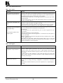
1
Kramer Electronics Ltd.
USER MANUAL
ELECTRONIC SWITCHERS
Models:
VS-55, VS-55A, VS-55V, VS-55YC
IMPORTANT: Before proceeding, please read paragraph entitled
"Unpacking and Contents"
Kramer Electronics LTD.
Table Of Contents
Section
Name
Page
1
1.1
1.2
2
3
4
4.1
5
5.1
5.2
5.3
5.4
6
6.1
7
8
8.1
8.2
8.3
8.4
9
10
10.1
10.2
11
Introduction
A word on video switchers
Factor affecting quality of results
Specifications
How do I get started?
Unpacking and contents
Optional accessories
Electronic switchers
Getting to know your VS-55 switcher
Getting to know your VS-55A switcher
Getting to know your VS-55V switcher
Getting to know your VS-55YC switcher
Installation
Rack mounting
Connecting to video or audio devices
Using the switchers
Connection and Controlling the switcher
Extending a switcher
Parallel signal switching
Remote controlling the switcher
Taking care of your switcher
Troubleshooting
Video signal
Audio signal
Limited warranty
1
1
1
2
3
3
3
4
4
5
6
7
8
8
8
8
8
9
10
11
11
12
12
12
13
List Of Illustrations
Figure
1
2
3
4
5
6
VS-55 Front and Rear panel features
VS-55A Front and Rear panel features
VS-55V Front and Rear panel features
VS-55YC Front and Rear panel features
Extending a Switcher – Adding inputs
Parallel signal switching
Page
4
5
6
7
9
10
List Of Tables
Table
1
2
3
4
5
VS-55 Front and Rear panel features
VS-55A Front and Rear panel features
VS-55V Front and Rear panel features
VS-55YC Front and Rear panel features
Pin configuration of the LINK connector
Page
4
5
6
7
11
1
INTRODUCTION
Congratulations on your purchase of this Kramer Switcher. Since 1981 Kramer has been dedicated to the
development and manufacture of high quality video/audio equipment. The Kramer line has become an
integral part of many of the best production and presentation facilities around the world. In recent years,
Kramer has redesigned and upgraded most of the line, making the best even better. Kramer’s line of
professional video/audio electronics is one of the most versatile and complete available, and is a true
leader in terms of quality, workmanship, price/performance ratio and innovation. In addition to the Kramer
line of high quality switchers, such as the one you have just purchased, Kramer also offers a full line of
high quality distribution amplifiers, processors, interfaces, controllers and computer-related products.
This manual includes configuration, operation and option information for the following Kramer switchers.
They are grouped here as they are similar in operation and features.
VS-55 – 5x1 Dual Wideband Switcher
VS-55A – 5x1 Stereo Audio Switcher
VS-55V – 5x1 Video Switcher
VS-55YC – 5x1 s-Video Switcher
1.1
A Word on Video Switchers
Switchers route one or more sources signals to one or more users. They vary in the number of inputs,
programming capability, number of outputs, operating format (audio, composite video, component, etc.)
and switching method (i.e., whether they switch during the vertical interval or not, whether they are
electronic, RS-232 or mechanically controlled). A switcher usually switches between several sources
(inputs) and one or more acceptors (outputs). A switcher that allows several inputs to be connected to
several outputs simultaneously is called a matrix switcher. Switchers may be of the electronic or
mechanical type. Most matrices are of the active electronic type, with many crosspoints. Vertical Interval
Switching, frequently used in video, ensures that the transition from one video source to another is smooth
and without interference. The switchers described in this manual are electronic switchers, have full
specifications, various control options and expandability and can be rack-mounted using special adapters.
Most of them offer a simple and economic solution for every video, audio or wideband-signal application.
1.2
Factors Affecting Quality of Results
There are many factors affecting the quality of results when signals are transmitted from a source to an
acceptor:
Connection cables - Low quality cables are susceptible to interference; they degrade signal quality
due to poor matching and cause elevated noise levels. They should therefore be of the best quality.
Sockets and connectors of the sources and acceptors - So often ignored, they should be of
highest quality, since "Zero Ohm" connection resistance is the objective. Sockets and connectors
also must match the required impedance (75ohm in video). Cheap, low quality connectors tend to
rust, thus causing breaks in the signal path.
Amplifying circuitry - Must have quality performance when high linearity, low distortion and low
noise operation are the desired end result.
Distance between sources and acceptors - Plays a major role in the result. For long distances
(over 15 meters) between sources and acceptors, special measures should be taken in order to avoid
cable losses. These include using higher quality cables or adding line amplifiers.
Interference from neighboring electrical appliances - These can have an adverse effect on signal
quality. Balanced audio lines are less prone to interference, but unbalanced audio should be
installed far from any mains power cables, electric motors, transmitters, etc. even when the cables
are shielded.
2
SPECIFICATIONS
Kramer Electronics Ltd.
1
VS-55
VS-55A
VS-55V
VS-55YC
Configuration
Dual 5x1
5x1
5x1
5x1
Inputs
5 dual signals, on
RCA connectors
5 stereo audio,
1Vpp/50 k on RCAs
5 Composite / single
Component,
1Vpp/75ohm on
BNCs
5 s-Video (Y/C)
1Vpp/75ohm (Y),
0.3Vpp/75ohm (C) on
4P connectors
Outputs
1 dual signal, on RCA 1 stereo audio,
connectors
1Vpp/100 ohms on
RCAs
LINK connector
(DB9), EXT
LINK connector
connector (RCA)
(DB9), EXT
connector (RCA)
1 Composite / single
Component,
1Vpp/75ohm on a
BNC
1 s-Video (Y/C)
1Vpp/75ohm (Y),
0.3Vpp/75ohm (C) on
a 4P connector
LINK connector
(DB9), EXT
connector (RCA)
LINK connector
(DB9), EXT
connector (RCA)
Switching
system
Electromechanical
Electromechanical
Electromechanical
Electromechanical
Vertical
Interval
NO
NO
YES
YES
Bandwidth
270 MHz
100 kHz
150 MHz
120 MHz (Y)
Control
5 front-panel touch
switches, remote
contact closure
5 front-panel touch
switches, remote
contact closure
5 front-panel touch
switches, remote
contact closure
5 front-panel touch
switches, remote
contact closure
DIFF. GAIN
NA
NA
0.88%
0.03%
DIFF. PHASE
NA
NA
0.35 Deg.
0.07 Deg.
THD
NA
<0.08%
NA
NA
S/N Ratio
NA
>78 dB
>73 dB
>78 dB (Y)
Max. Output
Up to 60 V
3 Vpp / 100 ohm
>1.6 Vpp/75 ohms
1.4 Vpp/75 ohms, (Y)
Accessories
12 V Power Supply
12 V Power Supply
12 V Power Supply
12 V Power Supply
Dimensions
(W, D, H)
16.5 x 12 x 4.5 (cm)
(6.5" x 4.7" x 1.8")
16.5 x 12 x 4.5 (cm)
(6.5" x 4.7" x 1.8")
16.5 x 12 x 4.5 (cm)
(6.5" x 4.7" x 1.8")
16.5 x 12 x 4.5 (cm)
(6.5" x 4.7" x 1.8")
Power Supply
12 VDC, 100 mA
12 VDC, 100 mA
12 VDC, 100 mA
12 VDC, 125 mA
Weight
0.62kg. (1.4 lbs.)
Approx.
0.62kg. (1.4 lbs.)
Approx.
0.66 kg. (1.46 lbs.)
Approx.
0.64 kg. (1.4 lbs.)
Approx.
Kramer Electronics Ltd.
2
3
HOW DO I GET STARTED?
The fastest way to get started is to take your time and do everything right the first time. Taking 15 minutes
to read the manual may save you a few hours later. You don’t even have to read the whole manual. If a
section doesn’t apply to you, you don’t have to spend your time reading it.
4
UNPACKING AND CONTENTS
The items contained in your Kramer accessory package are listed below. Please save the original box and
packaging materials for possible future transportation and shipment.
Switcher
User Manual
Kramer Concise Product Catalog
12 V DC Power Supply
4 Rubber Feet
4.1
Optional Accessories
The following accessories, which are available from Kramer, can enhance implementation of your
switcher. For information regarding cables and additional accessories, contact your Kramer dealer.
Rack Adapter (RK-50R) - Used to install smaller machines in a standard 1 or 2 U rack. One or more
machines may be installed on each adapter.
BNC "Y" Connector - Used for looping purposes and splits the incoming signal to enable connection
of an additional machine.
Termination Plug - Used to terminate the line to 75ohm for proper matching.
A video or s-Video distribution amplifier – such as the Kramer VM-3V, VM-50V, VM-10ARII, VM20ARII (video), VM-3S, VM-50YC, VM-5YC, VM-10YC (s-Video) for distributing the output signals
to several acceptors simultaneously.
An Audio Distribution Amplifier – such as Kramer VM-50A, VM-80A etc. for distributing the output
signals to several acceptors simultaneously.
A line amplifier – such as Kramer VM-9S, 104L (video), VM-9YC, 103YC (s-Video), for transmitting
signals over long distances, minimizing cable losses.
VIDEO TESTER - A new, unique, patented, indispensable tool for the video professional, the Video
Tester is used to test a video path leading to/from an amplifier. By pressing only one touch switch it can
trace missing signals, distinguish between good and jittery (VCR sourced) signals, and identify the
presence of good signals. Whenever a video signal is missing- because of bad connections, cable breaks
or faulty sources- the Video Tester is all you need.
Kramer Electronics Ltd.
3
5
ELECTRONIC SWITCHERS
This section describes the controls and connections of your switcher. Understanding all the controls and
connections helps you realize the full power of your switcher.
5.1
Getting to Know Your VS-55 switcher
The Kramer VS-55 is a high quality, dual wideband switcher for use with any set of dual signals such as
stereo audio, s-Video (Y/C), balanced audio, etc. It allows one of up to five dual sources to be routed to
one dual output. Since the signal path is passive, using high quality relays, the VS-55 can also operate in
the opposite direction, allowing one source to be routed to any one of five destinations.
The VS-55 also provides an EXT connector, which allows several units to be combined to form larger
switching systems. For example, two units will form a 10x1, three will form a 15x1, etc. A 12VDC
power supply is included for typical operation, but the optional model VA-50P can power up to six
Kramer devices requiring 12VDC. All Kramer VM-50 and VS-55 series products can be rack-mounted
using the model RK-50R kit that holds two units in one or two vertical rack spaces.
Panel features of the VS-55 are described in Figure 1 and Table 1.
Figure 1: VS-55 Front and Rear Panel Features
Table 1: VS-55 Front and Rear Panel Features
No.
1.
2.
3.
4.
5.
6.
7.
Feature
POWER Switch
INPUT Selector switches
INPUTS/OUTPUTS sockets
OUT/IN socket
EXT socket
12VDC socket
LINK socket
Kramer Electronics Ltd.
Function
Supplies power to the machine
Illuminated touch-button switches for selecting the desired input.
5 Dual RCA connectors that can serve as inputs or outputs.
1 Dual RCA connector that can serve as output or input.
A single RCA socket that is used for switcher extension
For connecting a DC power supply to the machine
A DB-9 female socket for parallel operation of several machines or
for contact closure remote control.
4
5.2
Getting to Know Your VS-55A switcher
The Kramer VS-55A is a high performance 5x1 switcher for stereo audio signals. Using RCA
connectors, one of up to five sources can be routed to an output. The VS-55A can be used as an
independent audio switcher, but is also designed to easily link with other VS-55 series Kramer
switchers such as the VS-55V for composite video, or the VS-55YC for s-Video, to form “audiofollow-video” systems.
The VS-55A also provides an EXT connector, which allows several units to be combined to form
larger switching systems. For example, two units will form a 10x1, three will form a 15x1, etc. A
12VDC-power supply is included for typical operation, but the optional model VA-50P can power up
to six Kramer devices requiring 12VDC. All Kramer VM-50 and VS-55 series products can be rackmounted using the model RK-50R rack kit which holds two units in one or two vertical rack spaces.
Panel features of the VS-55A are described in Figure 2 and Table 2.
Figure 2: VS-55A Front and Rear Panel Features
Table 2: VS-55A Front and Rear Panel Features
No.
Feature
Function
1.
POWER Switch
Supplies power to the machine
2.
INPUT Selector switches
Illuminated touch-button switches for selecting the desired input.
3.
INPUTS sockets
5 Dual RCA connectors that serve as the inputs to the machine.
4.
OUT socket
1 Dual RCA connector that serves as the output of the machine.
5.
EXT socket
A single RCA socket that is used for switcher extension
6.
12VDC socket
For connecting a DC power supply to the machine
7.
LINK socket
A DB-9 female socket for parallel operation of several machines or
for contact closure remote control.
Kramer Electronics Ltd.
5
5.3
Getting to Know Your VS-55V switcher
The Kramer VS-55V is a high performance 5x1 vertical interval switcher designed for composite video
signals. One of up to five sources can be routed to one monitor, projector, or other receiving device.
Since it switches during the vertical interval, transitions are glitch-free when sources share common
reference sync. The LINK connector is designed to allow the use of a VS-55A to form “audio-followvideo” systems. The VS-55V also provides an EXT connector, which allows several units to be
combined to form larger switching systems. For example, two units will form a 10x1, three will form a
15x1, etc. A 12VDC power supply is included for typical operation but the optional model VA-50P can
power up to six Kramer devices requiring 12VDC. All Kramer VM-50 and VS-55 series products can be
rack-mounted using the model RK-50R kit that holds two units in one or two vertical rack spaces.
Panel features of the VS-55V are described in Figure 3 and Table 3.
Figure 3: VS-55V Front and Rear Panel Features
Table 3: VS-55V Front and Rear Panel Features
No.
Feature
Function
1.
POWER Switch
Supplies power to the machine
2.
INPUT Selector switches
Illuminated touch-button switches for selecting the desired input.
3.
INPUTS sockets
5 BNC connectors that serve as the inputs to the machine.
4.
OUT socket
1 BNC connector that serves as the output of the machine.
5.
EXT socket
A single RCA socket that is used for switcher extension
6.
12VDC socket
For connecting a DC power supply to the machine
7.
LINK socket
A DB-9 female socket for parallel operation of several machines or
for contact closure remote control.
Kramer Electronics Ltd.
6
5.4
Getting to Know Your VS-55YC Switcher
The Kramer VS-55YC is a high performance 5x1 vertical interval switcher designed for s-Video (Y/C)
signals. One of up to five sources can be routed to one monitor, projector, or other receiving device.
Since it switches during the vertical interval, transitions are glitch-free when sources share common
reference sync. The LINK connector is designed to allow the use of a VS-55A to form “audio-followvideo” systems.
The VS-55YC also provides an EXT connector, which allows several units to be combined to form
larger switching systems. For example, two units will form a 10x1, three will form a 15x1, etc. A
12VDC-power supply is included for typical operation but the optional model VA-50P can power up to
six Kramer devices requiring 12VDC. All Kramer VM-50 and VS-55 series products can be rackmounted using the model RK-50R kit that holds two units in one or two vertical rack spaces.
Panel features of the VS-55YC are described in Figure 4 and Table 4.
Figure 4: VS-55YC Front and Rear Panel Features
Table 4: VS-55YC Front and Rear Panel Features
No.
Feature
Function
1.
POWER Switch
Supplies power to the machine
2.
INPUT Selector switches
Illuminated touch-button switches for selecting the desired input.
3.
INPUTS sockets
5 4P connectors that serve as the inputs to the machine.
4.
OUT socket
1 4P connector that serves as the output of the machine.
5.
EXT socket
A single RCA socket that is used for switcher extension
6.
12VDC socket
For connecting a DC power supply to the machine
7.
LINK socket
A DB-9 female socket for parallel operation of several machines or
for contact closure remote control.
Kramer Electronics Ltd.
7
6
6.1
7
INSTALLATION
Rack Mounting
The Kramer VS-55 series switchers may be rack-mounted in a standard 19” (1 or 2U) EIA rack assembly,
using a special Adapter (RK-50R - 1U or a 2U model) and a mounting bracket (see section 4.1). They can
also be table mounted using their rubber feet or the provided mounting brackets. These devices do not
require any specific spacing above or below the unit for ventilation. To rack mount any of the machines,
follow the installation instructions enclosed with the adaptor.
CONNECTING TO VIDEO OR AUDIO DEVICES
Video sources and output devices (such as monitors or recorders) may be connected to the switchers
through the BNC connectors (VS-55V), through the RCA connectors (VS-55, VS-55A), or through the 4P
connectors (VS-55YC) located on the back of the unit. The active inputs should be terminated by the
connecting source. The output signal format should match that of the input signal format, (e.g.: if
Composite video is input, then Composite video is output.) The signals supported by the various models
are video, s-video, RGB/YUV and audio signals.
8
USING THE SWITCHERS
8.1
Connection and controlling the Switchers
1. Connect all inputs of the "VS-55" family switcher to the sources to be switched, taking care to use
the right high quality cables. If linking is needed, interconnect the "linked" units with a DB9 maleto-male flat cable. Use video cables for video, audio cables for audio, etc. Use of the wrong cable
will impair output quality.
2. Connect the output of the "VS-55" type switcher to the input(s) of the acceptor, again using high
quality cables, turn on all units - sources, acceptors and the "VS-55" units, and you are ready to go.
3. If there no video signal is connected to input #1, then the VS-55V and VS-55YC units operate as
electronic switchers without Vertical Interval switching.
4. If you would like to extend the number of switched inputs, say forming a 10x1switcher, it can only
be done by using two machines of the same type, e.g., two VS-55Vs or two VS-55YCs, etc. In order
to do so, you should connect both EXT connectors to each other using a screened cable (an audio
cable will do the job well). Then connect outputs of both machines to each other using a "T"
connector. The combined output should then be connected to your acceptor. The concept of
operation is as following: the machines "sense" each other's status via the EXT connector, and when
a certain machine "senses" that the other is active, it shuts off it's own output circuitry, so in every
given instance, only one machine is actively connected to the acceptor.
5. The cables leading from the combined output to the acceptor's input and between the outputs of the
"VS-55" linked machines should be as short as possible.
6. Connect the "VS-55" machines to an appropriate 12 V DC source, observing correct polarity (center
pin is positive).
7. Turn on the sources, The "VS-55" switcher(s) and the acceptors.
8. If you have connected two or more machines via the EXT connector, when turning on the system,
sometimes a random combination of switches may light. Press any of the switches on any of the
interconnected "VS-55" units and the system will reset.
9. The VS-55 family allows remote controlling the switcher(s) using the LINK connector. Connect a
DB9 male plug with 9 wires leading from it to the remote location. A momentary touch of one of the
relevant pins (see table 1) to the common VCC pin (pin no. 8) forces the switcher to activate the
corresponding connection.
Kramer Electronics Ltd.
8
8.2
Extending a switcher
Figure 5 illustrates typical switching extension setup using two VS-55V switchers to create a 10x1
switcher.
First, connect a dual or shielded cable between the RCA EXT connectors of the machines. An audio cable
with two RCA connectors at the ends will do, if the distance between the switchers is no more than 5
meters.
Connect a “T” connector to the output of switcher 1.
Connect a high quality coax BNC to BNC cable between one of the edges of the “T” connector and the
output socket of switcher 2.
Connect a high quality coax BNC to BNC cable between the other edge of the “T” connector and the input
of your acceptor.
Connect 5 video sources (in this case using the VS-55V) to the input sockets of switcher 1.
Connect another 5 video sources to the input sockets of switcher 2.
Connect the power supply to the VS-55V machines.
Operate the VS-55V machines, the video sources and the acceptor.
The switches on the front of switcher 1 correspond to inputs 1-5, and on switcher 2 to inputs 6-10. When
you press a button on switcher 1, for example, all the other buttons, including the ones on switcher 2 will be
“off”.
To add more switchers (forming a 15x1, 20x1 etc. configuration), interconnect all EXT sockets from all
switchers using appropriate connectors, and “T” connect all outputs in a similar way: You should use a “T”
connector for all video outputs but the last. From the first machine’s “T” connector, connect a BNC to BNC
cable to the second machine’s “T” connector, from the second machine to the third and so on. The second
free “T” output of machine 1 should be connected to your video acceptor.
All interconnected machines should be close to each other, otherwise signal quality might be affected.
Figure 5: Extending a Switcher – Adding inputs
Kramer Electronics Ltd.
9
8.3
Parallel Signal Switching
Figure 6 illustrates a typical setup for switching s-Video and Audio signals in parallel, thus forming an
Audio follow video switcher. For parallel switching, as many switchers may be added as needed. For
example, three VS-55V switchers may be operated in parallel, forming a YUV or and RGB 5x1 switching
system.
Connect a DB-9 to DB-9 flat cable between the “LINK” connectors of the switchers.
Connect 5 s-Video sources to the input sockets of the VS-55YC switcher using high quality cables with
4P connectors at the ends.
Connect 5 stereo audio sources to the input sockets of the VS-55A switcher, using high quality cables
with RCA connectors at the ends.
Connect the output of of the VS-55YC to the input of your s-Video acceptor.
Connect the output of of the VS-55A to the input of your Audio acceptor.
Connect the power supply to the VS-55YC and VS-55A.
Operate the VS-55 machines, the sources and the acceptor.
For example, pressing switch #2 of the Input Selector switch bank of the VS-55YC, will automatically
activate switch #2 of the VS-55A.
Figure 6: Parallel Signal Switching
Kramer Electronics Ltd.
10
8.4
Remote controlling the Switchers
All the switchers of the VS-55 family may be contact-closure remote controlled via the “LINK” connector.
The distance between the switcher and the remote contact-closure assembly should preferably no be more
than 10 meters. Use table 5 below for identification of the DB-9 pin numbers and their use.
Connect a DB-9 male plug and cable (screened or flat) into the LINK connector of the VS-55 family
switcher.
Identify the wires corresponding to the relevant pins in table 5.
Pin #3 which is +8V (VCC) should be the common line of the contact closure assembly. Momentarily
touching one of the wires connected to pins 5, 6, 7, 8, 9 of the DB-9 connector will activate the
corresponding switch. For example – forming a momentary connection between pin #7 wire to the VCC
wire (pin #3) will force the switcher to activate switch #4. Connecting pin #9 wire momentarily to pin #3
wire will activate switch #2.
Be careful not to short pin #3 (VCC) and pin #2 (ground) as it may blow the fuse of the machine.
Connecting several switchers and their LINK connectors in parallel will enable the user to activate all
interconnected switchers with one momentary connection.
DB-9 Pin Number
2
3
5
6
7
8
9
1
4
Connected to:
Ground
VCC = 8V
Switch # 1
Switch # 5
Switch # 4
Switch # 3
Switch # 2
Not Connected
Not Connected
Table 5: Pin configuration of the “LINK” connector
9
TAKING CARE OF YOUR MACHINE
❒
❒
❒
❒
Do not locate your machine in an environment where it is susceptible to dust or moisture. Both of
these may damage the electronics, and cause erratic operation or failure.
Do not locate your machine where temperature and humidity may be excessive.
Do not clean your machine with abrasives or strong cleaners. Doing so may remove or damage the
finish, or may allow moisture to build up.
Take care not to allow dust or particles to build up inside unused or open connectors.
Kramer Electronics Ltd.
11
10
TROUBLESHOOTING
10.1 Video Signal
Problem
No video at the output device,
regardless of input selected.
Video level is too high or too
dim.
Noise bars "roll" up or down in
the output image
or:
Low Frequency Hum in the
output signal
Remedy
Confirm that your source and output devices are powered on and connected
properly. The input of your machine should be of an identical signal format at
the output of your source. Signals at the output of your machine should be of
an identical signal format as at the input of your display.
Confirm that any other device in the signal path have the proper input and/or
output selected.
Use the Video Tester to test the video path leading to/from your machine (see
section 4.1 "Video Tester")
Verify that the lines are well matched through 75ohm impedance; otherwise it
results in a video level that is too high or too dim.
Confirm that the connecting cables are of high quality and properly inserted.
Check level controls located on your source input device or output display.
Hum bars (ground loop) are caused by a difference in the ground potential of
any two or more devices connected to your signal path.
WARNING!
Do not disconnect the ground from any piece of video equipment in your
signal path!
Check the following to remove hum bars:
Confirm that all interconnected equipment is connected to the same phase of
power, if possible.
Remove equipment connected to that phase that may introduce noise, such as
motors, generators, etc.
Disconnect all interconnect cables and reconnect them one at a time until
ground loop reappears. Disconnect the affected cable and replace, or insert an
isolation transformer in the signal path.
10.2 Audio Signal
Problem
No audio at the output device,
regardless of input selected
Audio level is too low
Kramer Electronics Ltd.
Remedy
Confirm that your sources and output device are powered on and connected
properly. Audio signals connected to the input of your machine should be
properly wired to the output of your source. Audio signals connected to the
output of your machine should be properly wired to the input of your machine
or recorder.
Confirm that any other amplifiers in the signal path have the proper input
and/or output selected. Pay special attention to input amplifiers that may be
built into your acceptor.
Confirm that the connecting cables are of high quality and properly built. Take
special care in noting the wiring configuration of balanced to unbalanced
cables.
Check level controls located on your source input device or output display or
recorder.
12
LIMITED WARRANTY
Kramer Electronics (hereafter Kramer) warrants this product to be free from defects in material and
workmanship under the following terms.
HOW LONG IS THE WARRANTY
Labor and parts are warranted for three years from the date of the first customer purchase.
WHO IS PROTECTED
Only the first purchase customer may enforce this warranty.
WHAT IS COVERED AND WHAT IS NOT COVERED
Except as below, this warranty covers all defects in material or workmanship in this product. The following are
not covered by the warranty:
1)
2)
3)
Any product which is not distributed by Kramer or which is not purchased from an authorized Kramer
dealer. If you are uncertain as to whether a dealer is authorized, please contact Kramer at one of the agents
listed in the web site www kramerelectronics.com.
Any product, on which the serial number has been defaced, modified or removed.
Damage, deterioration or malfunction resulting from:
a)
Accident, misuse, abuse, neglect, fire, water, lightning or other acts of nature.
b) Unauthorized product modification, or failure to follow instructions supplied with the product.
c)
Repair or attempted repair by anyone not authorized by Kramer.
d) Any shipment of the product (claims must be presented to the carrier).
e)
Removal or installation of the product.
f)
Any other cause, which does not relate to a product defect.
g) Cartons, equipment enclosures, cables or accessories used in conjunction with the product.
WHAT WE WILL PAY FOR AND WHAT WE WILL NOT PAY FOR
We will pay labor and material expenses for covered items. We will not pay for the following:
1)
2)
3)
Removal or installations charges.
Costs of initial technical adjustments (set-up), including adjustment of user controls or programming. These
costs are the responsibility of the Kramer dealer from whom the product was purchased.
Shipping charges.
HOW YOU CAN GET WARRANTY SERVICE
1)
2)
3)
To obtain service on you product, you must take or ship it prepaid to any authorized Kramer service center.
Whenever warranty service is required, the original dated invoice (or a copy) must be presented as proof of
warranty coverage, and should be included in any shipment of the product. Please also include in any
mailing a contact name, company, address, and a description of the problem(s).
For the name of the nearest Kramer authorized service center, consult your authorized dealer.
Kramer Electronics Ltd.
13
LIMITATION OF IMPLIED WARRANTIES
All implied warranties, including warranties of merchantability and fitness for a particular purpose, are limited
in duration to the length of this warranty.
EXCLUSION OF DAMAGES
Kramer’s liability for any defective products is limited to the repair or replacement of the product at our option.
Kramer shall not be liable for:
1)
2)
Damage to other property caused by defects in this product, damages based upon inconvenience, loss of use
of the product, loss of time, commercial loss; or:
Any other damages, whether incidental, consequential or otherwise. Some countries may not allow
limitations on how long an implied warranty lasts and/or do not allow the exclusion or limitation of
incidental or consequential damages, so the above limitations and exclusions may not apply to you.
This warranty gives you specific legal rights, and you may also have other rights, which vary from place to
place.
NOTE: All products returned to Kramer for service must have prior approval. This may be obtained from your
dealer.
NOTICE
This equipment has been tested to determine compliance with the requirements of:
EN-50081:
EN-50082:
CFR-47
"Electromagnetic compatibility (EMC); generic emission standard. Part 1:
Residential, commercial and light industry".
"Electromagnetic compatibility (EMC) generic immunity standard. Part 1:
Residential, commercial and light industry environment".
FCC Rules and Regulations:
Part 15- “Radio frequency devices:
Subpart B- Unintentional radiators”
CAUTION
Any user who makes changes or modifications to the unit without the express approval of the manufacturer will
void user authority to operate the equipment.
Use only the recommended (or provided) power supply. Failing to do so will damage the machines.
Please use recommended interconnect cables to connect the machine to controllers and other components.
Kramer Electronics Ltd.
14
The list of Kramer distributors appears on our web site:
www.kramerelectronics.com
From the web site it is also possible to e-mail factory headquarters.
We welcome your questions, comments and feedback.
Kramer Electronics Ltd. 3 Am VeOlamo St., Jerusalem, Israel. Tel: +972-2-6544000, Fax: +972-2-6535369
Email: [email protected]