1
Contents
User Information
SIMATIC
C7-626 / C7-626 DP
Control Systems
Volume 2
Working with C7
Introduction
1
Commissioning (Startup)
2
Control
Controlling with the C7 CPU
3
Addressing, Assigning
Parameters, and How the C7 I/O
Works
4
I/O Diagnostics
5
Operating and Monitoring
Operating the C7 (General)
6
Standard O/I Functions
7
Data Areas for Communication
between the C7 OP and the
C7 CPU
8
Manual
Appendices
SFCs and SFBs in the C7 CPU
A
System Status List in the C7 CPU
B
C7 OP Functionality / Standard
Screens / Control Jobs / System
Messages
C
SIMATIC C7 and S7
Literature List
D
Siemens Worldwide
E
Glossary, Index
C79000-G7076-C627-01
ii
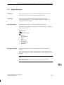
Safety Guidelines
!
!
!
This manual contains notices which you should observe to ensure your own personal safety, as well as to
protect the product and connected equipment. These notices are highlighted in the manual by a warning
triangle and are marked as follows according to the level of danger:
Danger
indicates that death, severe personal injury or substantial property damage will result if proper precautions are
not taken.
Warning
indicates that death, severe personal injury or substantial property damage can result if proper precautions are
not taken.
Caution
indicates that minor personal injury or property damage can result if proper precautions are not taken.
Note
draws your attention to particularly important information on the product, handling the product, or to a particular
part of the documentation.
Qualified Personnel
The device/system may only be set up and operated in conjunction with this manual.
Only qualified personnel should be allowed to install and work on this equipment. Qualified persons are
defined as persons who are authorized to commission, to ground, and to tag circuits, equipment, and systems in accordance with established safety practices and standards.
Correct Usage
!
Note the following:
Warning
This device and its components may only be used for the applications described in the catalog or the technical
description, and only in connection with devices or components from other manufacturers which have been
approved or recommended by Siemens.
This product can only function correctly and safely if it is transported, stored, set up, and installed correctly, and
operated and maintained as recommended.
Trademarks
SIMATICR and SINECR are registered trademarks of SIEMENS AG.
Third parties using for their own purposes any other names in this document which refer to
trademarks might infringe upon the rights of the trademark owners.
Copyright E Siemens AG 1996 All rights reserved
Disclaimer of Liability
The reproduction, transmission or use of this document or its contents is
not permitted without express written authority. Offenders will be liable for
damages. All rights, including rights created by patent grant or registration
of a utility model or design, are reserved.
We have checked the contents of this manual for agreement with the
hardware and software described. Since deviations cannot be precluded
entirely, we cannot guarantee full agreement. However, the data in this
manual are reviewed regularly and any necessary corrections included in
subsequent editions. Suggestions for improvement are welcomed.
Siemens AG
Automation Group
Industrial Automation Systems
Postfach 4848, D-90327 Nürnberg
E Siemens AG 1996
Technical data subject to change.
Siemens Aktiengesellschaft
C79000-G7076-C627
C7-626 / C7-626 DP Control Systems
C79000 G7076 C627 01
Contents
1
2
3
Introduction . . . . . . . . . . . . . . . . . . . . . . . . . . . . . . . . . . . . . . . . . . . . . . . . . . . . . . . . . . . . .
1-1
1.1
Controlling with C7 . . . . . . . . . . . . . . . . . . . . . . . . . . . . . . . . . . . . . . . . . . . . . . .
1-2
1.2
Operating and Monitoring with C7 . . . . . . . . . . . . . . . . . . . . . . . . . . . . . . . . . .
1-4
1.3
Overview of C7 . . . . . . . . . . . . . . . . . . . . . . . . . . . . . . . . . . . . . . . . . . . . . . . . . .
1-7
Commissioning (Startup) . . . . . . . . . . . . . . . . . . . . . . . . . . . . . . . . . . . . . . . . . . . . . . . .
2-1
2.1
Starting Up . . . . . . . . . . . . . . . . . . . . . . . . . . . . . . . . . . . . . . . . . . . . . . . . . . . . .
2-2
2.2
With a Loaded Configuration in the C7 OP . . . . . . . . . . . . . . . . . . . . . . . . . .
2-4
2.3
Without a Loaded Configuration in the C7 OP . . . . . . . . . . . . . . . . . . . . . . . .
2-5
2.4
Reloading a Configuration . . . . . . . . . . . . . . . . . . . . . . . . . . . . . . . . . . . . . . . . .
2-7
2.5
Selecting the C7 CPU Operating Mode and the DI/DO Status Display . . .
2-9
2.6
Resetting the C7 . . . . . . . . . . . . . . . . . . . . . . . . . . . . . . . . . . . . . . . . . . . . . . . . .
2-13
Controlling with the C7 CPU . . . . . . . . . . . . . . . . . . . . . . . . . . . . . . . . . . . . . . . . . . . . . .
3-1
3.1
C7 CPU: Overview . . . . . . . . . . . . . . . . . . . . . . . . . . . . . . . . . . . . . . . . . . . . . . .
3-2
3.2
Programming the C7 CPU . . . . . . . . . . . . . . . . . . . . . . . . . . . . . . . . . . . . . . . . .
3-3
3.3
Performance Characteristics of the C7 CPU . . . . . . . . . . . . . . . . . . . . . . . . .
3-4
3.4
C7 CPU Blocks . . . . . . . . . . . . . . . . . . . . . . . . . . . . . . . . . . . . . . . . . . . . . . . . . .
3-6
3.5
DP Interface of the C7-626 DP . . . . . . . . . . . . . . . . . . . . . . . . . . . . . . . . . . . . .
3-10
3.6
3.6.1
3.6.2
3.6.3
3.6.4
3.6.5
3.6.6
3.6.7
3.6.8
3.6.9
3.6.10
C7 CPU Parameters . . . . . . . . . . . . . . . . . . . . . . . . . . . . . . . . . . . . . . . . . . . . . .
Parameter Block “Clock Memory” . . . . . . . . . . . . . . . . . . . . . . . . . . . . . . . . . .
Parameter Block “Start-Up Characteristics” . . . . . . . . . . . . . . . . . . . . . . . . . .
Parameter Block “System Diagnostics” . . . . . . . . . . . . . . . . . . . . . . . . . . . . . .
Parameter Block “Retentive Areas”’ . . . . . . . . . . . . . . . . . . . . . . . . . . . . . . . .
Parameter Block “Hardware Interrupts” . . . . . . . . . . . . . . . . . . . . . . . . . . . . .
Parameter Block “Real-Time Clock” . . . . . . . . . . . . . . . . . . . . . . . . . . . . . . . .
Parameter Block “Time-Of-Day Interrupts” . . . . . . . . . . . . . . . . . . . . . . . . . . .
Parameter Block “Cyclic Interrupts” . . . . . . . . . . . . . . . . . . . . . . . . . . . . . . . . .
Parameter Block “Cycle Behavior” . . . . . . . . . . . . . . . . . . . . . . . . . . . . . . . . . .
Parameter Block “MPI Addresses” . . . . . . . . . . . . . . . . . . . . . . . . . . . . . . . . . .
3-12
3-13
3-14
3-15
3-16
3-17
3-18
3-19
3-20
3-21
3-22
3.7
3.7.1
3.7.2
3.7.3
3.7.4
Calculating the Scan Cycle Time and Response Time of the C7 CPU . . .
Calculation Example for the Scan Cycle Time . . . . . . . . . . . . . . . . . . . . . . . .
Calculation Example for the Response Time . . . . . . . . . . . . . . . . . . . . . . . . .
Hardware Interrupt Response Time . . . . . . . . . . . . . . . . . . . . . . . . . . . . . . . . .
Diagnostic Interrupt Response Time . . . . . . . . . . . . . . . . . . . . . . . . . . . . . . . .
3-23
3-30
3-31
3-33
3-35
C7-626 / C7-626 DP Control Systems
C79000-G7076-C627-01
iii
Contents
4
3.8
3.8.1
3.8.2
Bus Processing Times in the PROFIBUS-DP Network . . . . . . . . . . . . . . . .
Components of the Response Time with the C7-DP CPU as DP Master .
Bus Processing Time tDP . . . . . . . . . . . . . . . . . . . . . . . . . . . . . . . . . . . . . . . . .
3-36
3-37
3-38
3.9
Test and Reference Data Functions of the C7 CPU . . . . . . . . . . . . . . . . . . .
3-39
3.10
Loading / Erasing the C7 CPU Flash Memory . . . . . . . . . . . . . . . . . . . . . . . .
3-42
Addressing, Assigning Parameters, and How the C7 I/O Works . . . . . . . . . . . . .
4-1
4.1
Assigning Addresses to Signal Modules . . . . . . . . . . . . . . . . . . . . . . . . . . . . .
4-2
4.2
Addressing the C7 I/O . . . . . . . . . . . . . . . . . . . . . . . . . . . . . . . . . . . . . . . . . . . .
4-4
4.3
4.3.1
4.3.2
4.3.3
4.3.4
4-5
4-5
4-6
4-10
4.3.8
4.3.9
Use and Function of C7 Analog I/Os . . . . . . . . . . . . . . . . . . . . . . . . . . . . . . . .
Addressing the Analog I/Os . . . . . . . . . . . . . . . . . . . . . . . . . . . . . . . . . . . . . . .
Assigning Parameters to the Analog I/Os . . . . . . . . . . . . . . . . . . . . . . . . . . . .
Representation of Analog Values . . . . . . . . . . . . . . . . . . . . . . . . . . . . . . . . . . .
Representation of Analog Values for the Measuring Ranges of the
Analog Inputs . . . . . . . . . . . . . . . . . . . . . . . . . . . . . . . . . . . . . . . . . . . . . . . . . . . .
Representation of Analog Values for the Output Range of the
Analog Outputs . . . . . . . . . . . . . . . . . . . . . . . . . . . . . . . . . . . . . . . . . . . . . . . . . .
Conversion and Scan Cycle Time of the Analog I/Os . . . . . . . . . . . . . . . . . .
Conversion, Scan Cycle, Settling and Response Times of the
Analog Outputs . . . . . . . . . . . . . . . . . . . . . . . . . . . . . . . . . . . . . . . . . . . . . . . . . .
Behavior of the Analog I/Os . . . . . . . . . . . . . . . . . . . . . . . . . . . . . . . . . . . . . . .
Time Interrupt / Interrupt Cycle . . . . . . . . . . . . . . . . . . . . . . . . . . . . . . . . . . . . .
4.4
4.4.1
4.4.2
4.4.3
4.4.4
4.4.5
4.4.6
4.4.7
Use and Function of the Universal Inputs . . . . . . . . . . . . . . . . . . . . . . . . . . . .
Addressing the Universal Inputs . . . . . . . . . . . . . . . . . . . . . . . . . . . . . . . . . . . .
Assigning Parameters to the Universal Inputs . . . . . . . . . . . . . . . . . . . . . . . .
Interrupt Inputs . . . . . . . . . . . . . . . . . . . . . . . . . . . . . . . . . . . . . . . . . . . . . . . . . .
Counters . . . . . . . . . . . . . . . . . . . . . . . . . . . . . . . . . . . . . . . . . . . . . . . . . . . . . . . .
Counter Interrupts . . . . . . . . . . . . . . . . . . . . . . . . . . . . . . . . . . . . . . . . . . . . . . . .
Frequency Counters . . . . . . . . . . . . . . . . . . . . . . . . . . . . . . . . . . . . . . . . . . . . . .
Period Time Measurement . . . . . . . . . . . . . . . . . . . . . . . . . . . . . . . . . . . . . . . .
4-19
4-19
4-23
4-25
4-27
4-30
4-32
4-34
4.5
Data Set Description for Parameter Block of the C7 Analog I/Os
and Universal Inputs . . . . . . . . . . . . . . . . . . . . . . . . . . . . . . . . . . . . . . . . . . . . . .
4-37
Examples for Programming the Analog I/Os and the Universal Inputs . . .
Block for Scaling Analog Output Values . . . . . . . . . . . . . . . . . . . . . . . . . . . . .
Block for Scaling Analog Input Values . . . . . . . . . . . . . . . . . . . . . . . . . . . . . . .
Example for Programming Counters . . . . . . . . . . . . . . . . . . . . . . . . . . . . . . . .
4-40
4-40
4-43
4-46
Diagnostics . . . . . . . . . . . . . . . . . . . . . . . . . . . . . . . . . . . . . . . . . . . . . . . . . . . . . . . . . . . . .
5-1
5.1
Diagnostic Messages . . . . . . . . . . . . . . . . . . . . . . . . . . . . . . . . . . . . . . . . . . . . .
5-2
5.2
Diagnostic Data of the C7 Analog I/Os and Universal Inputs . . . . . . . . . . .
5-4
5.3
Constraints and Responses of the Diagnostic Evaluation . . . . . . . . . . . . . .
5-8
Operating the C7 (General) . . . . . . . . . . . . . . . . . . . . . . . . . . . . . . . . . . . . . . . . . . . . . . .
6-1
6.1
Screen Layout . . . . . . . . . . . . . . . . . . . . . . . . . . . . . . . . . . . . . . . . . . . . . . . . . . .
6-2
6.2
Keyboard . . . . . . . . . . . . . . . . . . . . . . . . . . . . . . . . . . . . . . . . . . . . . . . . . . . . . . .
6-3
6.3
6.3.1
Input / Output Fields . . . . . . . . . . . . . . . . . . . . . . . . . . . . . . . . . . . . . . . . . . . . . .
Numeric Fields . . . . . . . . . . . . . . . . . . . . . . . . . . . . . . . . . . . . . . . . . . . . . . . . . .
6-6
6-7
4.3.5
4.3.6
4.3.7
4.6
4.6.1
4.6.2
4.6.3
5
6
iv
4-11
4-13
4-14
4-15
4-16
4-17
C7-626 / C7-626 DP Control Systems
C79000-G7076-C627-01
Contents
7
8
6.3.2
6.3.3
String Fields . . . . . . . . . . . . . . . . . . . . . . . . . . . . . . . . . . . . . . . . . . . . . . . . . . . . .
Symbolic Fields . . . . . . . . . . . . . . . . . . . . . . . . . . . . . . . . . . . . . . . . . . . . . . . . . .
6-9
6-12
6.4
Switching the Active Window . . . . . . . . . . . . . . . . . . . . . . . . . . . . . . . . . . . . . .
6-13
6.5
6.5.1
6.5.2
6.5.3
6.5.4
C7 System Settings . . . . . . . . . . . . . . . . . . . . . . . . . . . . . . . . . . . . . . . . . . . . . .
Standard Screen: System Settings . . . . . . . . . . . . . . . . . . . . . . . . . . . . . . . . .
Standard Screen: Printer Settings . . . . . . . . . . . . . . . . . . . . . . . . . . . . . . . . . .
Blanking Circuit . . . . . . . . . . . . . . . . . . . . . . . . . . . . . . . . . . . . . . . . . . . . . . . . . .
Contrast and Brightness Adjustment . . . . . . . . . . . . . . . . . . . . . . . . . . . . . . . .
6-15
6-15
6-16
6-17
6-18
6.6
Setting / Changing the Operating Mode . . . . . . . . . . . . . . . . . . . . . . . . . . . . .
6-19
6.7
6.7.1
6.7.2
6.7.3
Password Protection . . . . . . . . . . . . . . . . . . . . . . . . . . . . . . . . . . . . . . . . . . . . .
Logging In on the C7 . . . . . . . . . . . . . . . . . . . . . . . . . . . . . . . . . . . . . . . . . . . . .
Logging Out on the C7 (Logout) . . . . . . . . . . . . . . . . . . . . . . . . . . . . . . . . . . . .
Password Management . . . . . . . . . . . . . . . . . . . . . . . . . . . . . . . . . . . . . . . . . . .
6-21
6-22
6-23
6-23
6.8
Hardware Test . . . . . . . . . . . . . . . . . . . . . . . . . . . . . . . . . . . . . . . . . . . . . . . . . . .
6-25
Standard O/I Functions . . . . . . . . . . . . . . . . . . . . . . . . . . . . . . . . . . . . . . . . . . . . . . . . . .
7-1
7.1
7.1.1
7.1.2
7.1.3
7.1.4
Screens . . . . . . . . . . . . . . . . . . . . . . . . . . . . . . . . . . . . . . . . . . . . . . . . . . . . . . . .
The C7 in Action Using an Example . . . . . . . . . . . . . . . . . . . . . . . . . . . . . . . .
Screen Elements . . . . . . . . . . . . . . . . . . . . . . . . . . . . . . . . . . . . . . . . . . . . . . . . .
Selecting a Screen . . . . . . . . . . . . . . . . . . . . . . . . . . . . . . . . . . . . . . . . . . . . . . .
Standard Screens . . . . . . . . . . . . . . . . . . . . . . . . . . . . . . . . . . . . . . . . . . . . . . . .
7-2
7-2
7-4
7-5
7-6
7.2
7.2.1
7.2.2
7.2.3
7.2.4
7.2.5
7.2.6
Messages . . . . . . . . . . . . . . . . . . . . . . . . . . . . . . . . . . . . . . . . . . . . . . . . . . . . . . .
Event and Alarm Messages . . . . . . . . . . . . . . . . . . . . . . . . . . . . . . . . . . . . . . .
General Features . . . . . . . . . . . . . . . . . . . . . . . . . . . . . . . . . . . . . . . . . . . . . . . .
Current Messages . . . . . . . . . . . . . . . . . . . . . . . . . . . . . . . . . . . . . . . . . . . . . . .
Stored Messages . . . . . . . . . . . . . . . . . . . . . . . . . . . . . . . . . . . . . . . . . . . . . . . .
Standard Screen: Message Processing . . . . . . . . . . . . . . . . . . . . . . . . . . . . .
System Messages . . . . . . . . . . . . . . . . . . . . . . . . . . . . . . . . . . . . . . . . . . . . . . .
7-7
7-7
7-8
7-10
7-13
7-15
7-16
7.3
7.3.1
7.3.2
7.3.3
Recipes . . . . . . . . . . . . . . . . . . . . . . . . . . . . . . . . . . . . . . . . . . . . . . . . . . . . . . . . .
Processing and Transferring Data Records . . . . . . . . . . . . . . . . . . . . . . . . . .
Setting Up and Editing Data Records . . . . . . . . . . . . . . . . . . . . . . . . . . . . . . .
Parameter Records . . . . . . . . . . . . . . . . . . . . . . . . . . . . . . . . . . . . . . . . . . . . . .
7-17
7-19
7-23
7-26
7.4
Printing . . . . . . . . . . . . . . . . . . . . . . . . . . . . . . . . . . . . . . . . . . . . . . . . . . . . . . . . .
7-28
7.5
Status / Force with the C7 . . . . . . . . . . . . . . . . . . . . . . . . . . . . . . . . . . . . . . . . .
7-30
Data Areas for Communication between the C7 OP and the C7 CPU . . . . . . . . .
8-1
8.1
Communication Parameters in a Configuration . . . . . . . . . . . . . . . . . . . . . . .
8-2
8.2
Overview of User Data Areas . . . . . . . . . . . . . . . . . . . . . . . . . . . . . . . . . . . . . .
8-3
8.3
Event and Alarm Messages . . . . . . . . . . . . . . . . . . . . . . . . . . . . . . . . . . . . . . .
8-4
8.4
8.4.1
8.4.2
8.4.3
Keyboard and LED Image . . . . . . . . . . . . . . . . . . . . . . . . . . . . . . . . . . . . . . . . .
System Keyboard Image . . . . . . . . . . . . . . . . . . . . . . . . . . . . . . . . . . . . . . . . . .
Function Keyboard Image . . . . . . . . . . . . . . . . . . . . . . . . . . . . . . . . . . . . . . . . .
LED Image . . . . . . . . . . . . . . . . . . . . . . . . . . . . . . . . . . . . . . . . . . . . . . . . . . . . . .
8-8
8-9
8-10
8-11
8.5
Screen Number Area . . . . . . . . . . . . . . . . . . . . . . . . . . . . . . . . . . . . . . . . . . . . .
8-12
8.6
Trend Request and Transfer Areas . . . . . . . . . . . . . . . . . . . . . . . . . . . . . . . . .
8-13
C7-626 / C7-626 DP Control Systems
C79000-G7076-C627-01
v
Contents
8.7
User Version . . . . . . . . . . . . . . . . . . . . . . . . . . . . . . . . . . . . . . . . . . . . . . . . . . . .
8-15
8.8
8.8.1
8.8.2
8.8.3
Interface Area . . . . . . . . . . . . . . . . . . . . . . . . . . . . . . . . . . . . . . . . . . . . . . . . . . .
Control and Checkback Bits . . . . . . . . . . . . . . . . . . . . . . . . . . . . . . . . . . . . . . .
Data Areas in the Interface Area . . . . . . . . . . . . . . . . . . . . . . . . . . . . . . . . . . .
Example for Activating a Control Job . . . . . . . . . . . . . . . . . . . . . . . . . . . . . . .
8-16
8-17
8-18
8-20
8.9
8.9.1
8.9.2
8.9.3
8.9.4
Recipes . . . . . . . . . . . . . . . . . . . . . . . . . . . . . . . . . . . . . . . . . . . . . . . . . . . . . . . . .
Transferring Data Records . . . . . . . . . . . . . . . . . . . . . . . . . . . . . . . . . . . . . . . .
Addressing Recipes and Data Records, and the Required Data Areas . .
Synchronization during Transfer – Normal Case . . . . . . . . . . . . . . . . . . . . . .
Synchronization during Transfer – Special Cases . . . . . . . . . . . . . . . . . . . .
8-21
8-22
8-22
8-24
8-25
8.10
Writing Variables Indirectly . . . . . . . . . . . . . . . . . . . . . . . . . . . . . . . . . . . . . . . .
8-26
8.11
Notes on Optimization . . . . . . . . . . . . . . . . . . . . . . . . . . . . . . . . . . . . . . . . . . . .
8-27
SFCs and SFBs in the C7 CPU . . . . . . . . . . . . . . . . . . . . . . . . . . . . . . . . . . . . . . . . . . . .
A-1
A.1
SFCs and SFBs . . . . . . . . . . . . . . . . . . . . . . . . . . . . . . . . . . . . . . . . . . . . . . . . .
A-2
A.2
IEC Functions . . . . . . . . . . . . . . . . . . . . . . . . . . . . . . . . . . . . . . . . . . . . . . . . . . .
A-6
B
System Status List in the C7 CPU . . . . . . . . . . . . . . . . . . . . . . . . . . . . . . . . . . . . . . . .
B-1
C
C7 OP Functionality / Standard Screens / Control Jobs / System Messages . .
C-1
C.1
C7 OP Functionality . . . . . . . . . . . . . . . . . . . . . . . . . . . . . . . . . . . . . . . . . . . . . .
C-2
C.2
Control Jobs and Their Parameters . . . . . . . . . . . . . . . . . . . . . . . . . . . . . . . . .
C-5
C.3
System Messages . . . . . . . . . . . . . . . . . . . . . . . . . . . . . . . . . . . . . . . . . . . . . . .
C-9
C.4
Internal Errors . . . . . . . . . . . . . . . . . . . . . . . . . . . . . . . . . . . . . . . . . . . . . . . . . . .
C-25
D
SIMATIC C7 and S7 Literature List . . . . . . . . . . . . . . . . . . . . . . . . . . . . . . . . . . . . . . . .
D-1
E
Siemens Worldwide . . . . . . . . . . . . . . . . . . . . . . . . . . . . . . . . . . . . . . . . . . . . . . . . . . . . .
E-1
A
vi
Glossary . . . . . . . . . . . . . . . . . . . . . . . . . . . . . . . . . . . . . . . . . . . . . . . . . . . . . . . . . .
Glossary-1
Index . . . . . . . . . . . . . . . . . . . . . . . . . . . . . . . . . . . . . . . . . . . . . . . . . . . . . . . . . . . . .
Index-1
C7-626 / C7-626 DP Control Systems
C79000-G7076-C627-01
1
Introduction
Overview
This chapter will inform you about the prerequisites for programming the C7
and its functionality as an operator interface device.
Note
The C7 consists of two independent units, each with its own processor:
- C7 CPU and
- C7 OP
These components are explicitly named as required.
What do you
Require to Operate
the C7?
You require the following equipment and tools:
S A programming device or PC with multipoint interface, and a
programming device cable
S STEP 7 applications from version 2, including documentation
S The ProTool configuring tool from version 2.10, including documentation
S C7 connector set for I/O and power supply
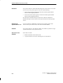
Summary of
Sections
In Section
You Will Find
On Page
1.1
Controlling with C7
1-2
1.2
Operating and Monitoring with C7
1-4
1.3
Overview of C7
1-7
C7-626 / C7-626 DP Control Systems
C79000-G7076-C627-01
1-1
Introduction
1.1
Controlling with C7
1
Overview
The user program which controls the process that is to be visualized by the
operator interface part of the C7 runs on the C7 CPU.
C7 CPU
The operation of the C7 CPU is determined by the following functional
elements:
Program Memory
This contains the user program.
Processor
The processor executes the program cyclically:
S At the beginning of the cycle, the processor reads the signal states of all
inputs and generates the process-image input table (PII).
S The program is processed step-by-step, taking into account all counter
and timer values and bit memories.
S The processor stores the signal states resulting from program execution in
the process-image output table (PIQ). The states are then transferred to
the outputs.
The C7 CPU is independent of the C7 OP. It has a separate MPI address and
is connected to the C7 OP via the multipoint interface.
Programming
Languages
At present, the C7 CPU generally supports two programming languages:
S STL: Statement List consists of a series of statements. Each statement in
your program contains instructions which mnemonically represent a
function of the C7 CPU.
S LAD: A Ladder diagram is a graphic programming language that
resembles electrical circuit diagrams.
Other programming languages are, for example, SCL and HiGraph.
1-2
C7-626 / C7-626 DP Control Systems
C79000-G7076-C627-01
Introduction
What to Program
With
Which Devices
to Use
The tool with which you create user programs is STEP 7 for Statement List,
Ladder Logic and IDE (Integrated Development Environment). You can find
the operation notes necessary for programming in the User Manual /231/.
Use the manuals listed in the preface for the individual languages.
STEP 7 and C IDE run on a programming device or PC. You can operate
these devices independently of the C7. You should connect the programming
device/PC to the C7 via the multipoint interface only when you wish to load
your user program into the C7.
C7-626 / C7-626 DP Control Systems
C79000-G7076-C627-01
1-3
1
Introduction
1.2
Operating and Monitoring with C7
1
Machine-Type
Monitoring and
Control
Electronically controlled machines are usually supervised and controlled “on
the spot”. Depending on the size and complexity of the machine or system,
the requirements for O/I systems differ greatly.
C7 Devices with
Graphics
The C7-626 and the C7-626 DP are control systems with graphics capability.
These devices enable you to:
S Visualize processes, machines and systems as semigraphic or full graphic
images.
S Intervene in the process flow using the integrated keyboard.
C7 OP
The C7 OP processes the O/I functions configured for the C7. It is
independent of the C7 CPU and is still operable, for example, if the C7 CPU
is in STOP mode. The C7 OP is assigned a separate MPI address and
connected to the C7 CPU via the multipoint interface. This interface forms
the link between the C7 OP and the computer used for configuring
(programming device/PC).
Displays
“One picture is worth a thousand words” goes the familiar saying.
This is particularly true of machine and system monitoring where it is
important to provide the operator with clear and easy-to-understand
information about the state of the process.
Process values and process sequences are shown by displays which can
contain graphics, texts and values. Process values in a system are often
related in some way. Displays show this relationship and thus represent an
image of the process.
Full Graphic Plant
Screens
The C7 enables you to represent machines and plants as full graphic
screens. This improves operator orientation.
Bars and Curves
You can show current process values (for example, filling level and speed) as
numeric values, or symbolically as text or bars.
Curves are a particularly good way of showing changeable process values
(for example, changes in temperature) over a period of time.
Symbolic Graphics
Symbolic graphics are another way to indicate process values. Symbolic
graphics are graphic elements (that is, bit maps) which are indicated
alternately to show different process states (for example, valve open or
closed).
1-4
C7-626 / C7-626 DP Control Systems
C79000-G7076-C627-01
Introduction
Process
Manipulation
The operator can use the integrated keyboard in the C7 to intervene in the
process sequence.
1
For example, you can control actuators (for example, valves) by specifying
process values (for example, setpoints).
Features important to operator control include ease of handling, short training
periods, and a high degree of reliability.
You can configure the structure of the C7 operating environment as required
(in other words, you can tailor operator control to your particular
application).
A few features:
S Freely configurable function keys
S Softkeys
S Pop-up windows for symbolic entries
Messages
Process or machine states (for example, the current operating mode) are
displayed by the C7 as plain-text event messages.
Alarm messages provide information on critical machine states.
Current measured values (for example, temperatures, speeds, etc.) can also
be included in the text of event or alarm messages.
Event and alarm messages are stored with date and time in a message buffer.
At the same time, all message events can be printed (if message logging is
switched on and a printer is connected).
Information Texts
Information texts can be configured. You can use them to give the operator
additional information which will help him/her to correct a malfunction.
Recipes
Complete blocks of machine data can be stored as recipes on the C7.
The structure of a recipe is specified during configuration. It makes no
difference whether the recipes are “real recipes” or only piece number
specifications, traversing paths or temperature progressions.
You can change or redefine recipe data directly on the C7.
Password
Protection
The C7 offers password protection. Each operator can be assigned a different
password. A password level can then be used to enable or disable each
operator’s access to special operating functions. This prevents incorrect
entries and improves system security.
C7-626 / C7-626 DP Control Systems
C79000-G7076-C627-01
1-5
Introduction
Multiple
Languages
1
All messages and texts for screens can be stored in the C7 in up to three
different languages.
This permits international use even when operating personnel speak different
languages.
Programming
Device Functions
1-6
The “Status/Force Variable” programming device functions are available for
testing and troubleshooting. They can be used on the C7 OP to specify and
change address areas in the C7 CPU. This makes on-site troubleshooting fast
even without a programmer.
C7-626 / C7-626 DP Control Systems
C79000-G7076-C627-01
Introduction
1.3
Overview of C7
1
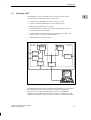
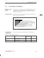
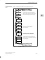
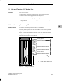
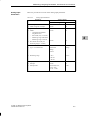
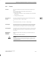
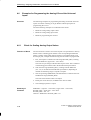
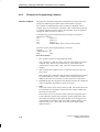
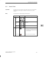
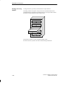
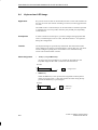
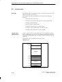
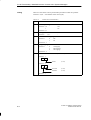
The SIMATIC C7-626/C7-626 DP control systems consist of several
components that are optimally tuned to one another:
S A CPU from the SIMATIC S7-300 PLC range (C7 CPU)
S A graphic-oriented COROS OP (C7 OP) with printer port
S Integral digital and analog I/O (C7 I/O)
S An integrated IM 360 module (C7 IM) for expanding the C7-626 or
C7-626 DP with S7-300 modules
S An interface for communicating with programming devices/PCs and
further S7 CPUs, C7 control systems and OPs.
S A DP interface to connect DP slaves.
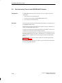
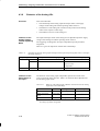
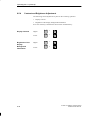
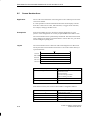
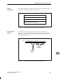
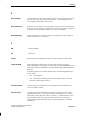
C7
C7 PLC
CPU memory
OP memory
C7 CPU
C7 OP
C7 OP
C7
DP interface
Printer
port
C7 I/O
C7 IM
MPI
STEP 7
ProTool
Figure 1-1
Components of the C7
The individual functional units integrated in the SIMATIC C7 correspond to
the modules and devices that can be used in modular configurations
comprising S7-300 CPUs, COROS OPs, etc. The C7’s I/O expansion
capability via its IM interface permits the connection of SIMATIC S7-300
modules distributed over three racks with a maximum of 24 S7-300 modules.
C7-626 / C7-626 DP Control Systems
C79000-G7076-C627-01
1-7
Introduction
The general functionality of the C7 also corresponds to a configuration with
standard modules in the PLC and OP ranges. The individual components
operate independently of one another and each processor has a separate
memory.
1
STEP 7 is used for programming the C7 CPU whereas the C7 OP is
programmed with ProTool. Both tools run under Windows either on
programming devices or PCs.
1-8
C7-626 / C7-626 DP Control Systems
C79000-G7076-C627-01
2
Commissioning (Startup)
Overview
In this chapter, you will learn:
S How the C7 behaves on startup
S What you must do if the configuration has (not) been loaded
S How you can activate the C7 CPU operating modes RUN-P, RUN,
STOP and MRES
S How you can activate the DI/DO status display
S How you perform a memory reset of the C7 controller
Summary of
Sections
In Section
You Will Find
On Page
2.1
Starting Up
2-2
2.2
With a Loaded Configuration in the C7 OP
2-3
2.3
Without a Loaded Configuration in the C7 OP
2-4
2.4
Reloading a Configuration
2-6
2.5
Selecting the C7 CPU Operating Mode and the
DI/DO Status Display
2-8
2.6
Resetting the C7
C7-626 / C7-626 DP Control Systems
C79000-G7076-C627-01
2-11
2-1
Commissioning (Startup)
2.1
Starting Up
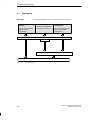
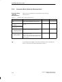
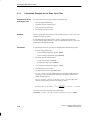
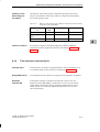
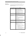
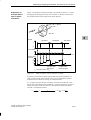
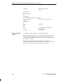
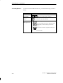
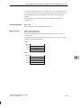
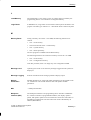
Overview
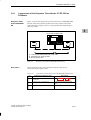
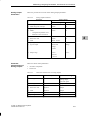
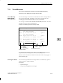
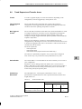
The following diagram shows the basic steps when starting up:
2
With Configuration
(default)
Without Configuration
There is no configuration
/ firmware in the C7 OP.
The C7 OP is operated
with the loaded
configuration.
Reloading the
Configuration
The C7 OP should work
with a new/modified
configuration.
Switch on C7 power supply
C7 OP
Transfer configuration data to the C7 OP
Start-Up Screen
Figure 2-1
2-2
Start-Up Process
C7-626 / C7-626 DP Control Systems
C79000-G7076-C627-01
Commissioning (Startup)
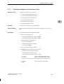
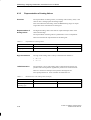
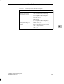
2.2
With a Loaded Configuration in the C7 OP
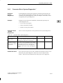
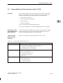
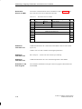
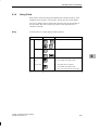
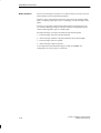
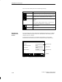
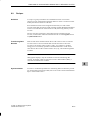
Startup
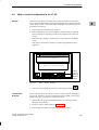
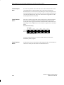
After connecting the power supply, the C7 performs a self-test. During this
test, it checks the functionality of the most important device components and
shows the test results via the status LEDs and display. The following start-up
procedure is carried out:
1. The C7 performs a self-test after power on.
2. If the configuration has not been loaded, a contrast setting is requested.
The C7 performs an operating system test for both units (C7 CPU and
C7 OP).
3. During the start-up phase (1 and 2), the C7 CPU remains in the STOP
mode.
After the C7 OP has been started up, the following standard screen is
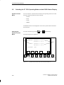
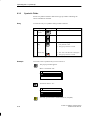
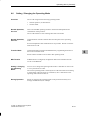
displayed:
!
399 Startup complete
Basic C7-626 picture
1
Figure 2-2
2
3
4
5
Softkey
icons for
selecting
standard
screens
Basic C7 Picture (Example)
4. The start-up message displayed can be confirmed by pressing
Load Control
Program
.
The C7 OP must access data in the C7 CPU in order to operate and monitor
the process. Therefore, the user program must first be loaded, if this has not
already been done. Load the user program as follows:
1. Transfer the user program and the data blocks on your programming
device/PC using STEP 7.
2. Set the C7 CPU to STOP mode (see Section 2.5).
3. Start the copy procedure from the programming device/PC.
C7-626 / C7-626 DP Control Systems
C79000-G7076-C627-01
2-3
2
Commissioning (Startup)
2.3
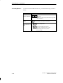
Without a Loaded Configuration in the C7 OP
Overview
2
There is no configuration loaded on startup. This must, however, be loaded in
order to operate the C7 OP, otherwise the operating function “C7 CPU
Operating Mode Selection” will not be available. You can only set the
C7 CPU operating modes RUN-P, RUN, STOP and MRES on the C7 if a
configuration is loaded.
Note
When starting up the C7 without configuration data, you must load the
configuration data via the V.24 serial interface.
Loading the
Configuration
Load the basic configuration so that the explanations in this manual relate to
this configuration.
Proceed as follows:
1. Connect the V.24 serial interface of the C7 OP (see Figure 2-8 in Volume
1) to the programming device/PC using a suitable standard cable.
2. Switch on the C7 power supply.
As no configuration is loaded, the C7 automatically goes into transfer
mode and waits for a data transfer.
3. Transfer the basic configuration from the programming device/PC to the
C7 OP.
The firmware of the C7 OP is automatically transferred as well.
Note
The exact procedure is explained in the ProTool description.
After a successful transfer, the C7 OP is restarted.
4. The displayed message can be removed by pressing
2-4
.
C7-626 / C7-626 DP Control Systems
C79000-G7076-C627-01
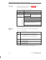
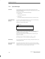
Commissioning (Startup)
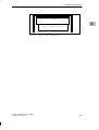
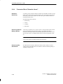
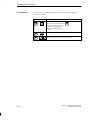
!
339 Startup complete
2
Basic C7-626 picture
Figure 2-3
C7-626 / C7-626 DP Control Systems
C79000-G7076-C627-01
Basic C7 Picture with Message 339
2-5
Commissioning (Startup)
2.4
Reloading a Configuration
Overview
2
There are two ways of loading a configuration onto the C7 OP:
S via the multipoint interface (see Figure 2.9, Volume 1)
S via the V.24 serial interface.
Below, you will find a description of how to replace an existing configuration
on the C7 OP with another.
MPI Transfer
C7 OP configurations can be transferred via an MPI connection to the C7 OP.
The only requirement is that the C7 OP must already have a loaded configuration and the MPI transfer function must be configured.
Loading the
Configuration
To load the configuration, proceed as follows:
1. Connect the multipoint interface of the C7 to the configuring computer
using a programming device/PC cable.
Note
S If the C7 OP and the configuring computer are already included in the
MPI bus, then there is no need to change cables when transferring the
configuration.
2. Connect the OP to the power supply.
3. Select MPI transfer in the standard screen System Settings Operating
Modes. The C7 OP is now restarted.
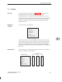
4. The following screen is displayed in MPI transfer mode.
2-6
C7-626 / C7-626 DP Control Systems
C79000-G7076-C627-01
Commissioning (Startup)
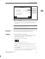
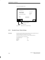
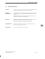
MPI DOWNLOAD
MPI Baud rate
= 187.5 kBaud
MPI Station address
001
Indication of the
current (configured)
transmission rate/
entry of another
transmission rate
Indication of the
configured C7 OP
station address
Download telegram type:
Download address:
serial
Downl.
ESC
Switch to transfer mode (serial)
Figure 2-4
Cancel MPI transfer mode
MPI Transfer
5. Transfer the configuration from the configuring computer (programming
device/PC) to the C7 OP. This procedure is described in the ProTool
User’s Guide.
Note
The transmission rate is fixed at 187.5 Kbps.
Transferring via a
V.24 Interface
With serial transfers, the transfer of the configuration is carried out via a V.24
connection between the programming device/PC and the C7 OP.
Loading the
Configuration
To load the configuration, proceed as follows:
1. Connect the V.24 interface of the C7 OP with the configuring computer
(programming device/PC) using a suitable standard cable.
2. Switch on the C7 power supply.
3. During startup, press the key combination
to switch to the transfer mode of the C7 OP.
In the top line of the display, the following line appears: Trans-Mode.
4. Transfer the configuration from the programming device/PC to the
C7 OP.
The existing configuration in the C7 OP will then be overwritten with the
new configuration.
Once the transfer has been successfully completed, the C7 OP will restart
and display the start-up screen of the loaded configuration.
C7-626 / C7-626 DP Control Systems
C79000-G7076-C627-01
2-7
2
Commissioning (Startup)
2.5
2
Selecting the C7 CPU Operating Mode and the DI/DO Status Display
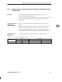
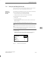
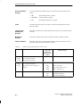
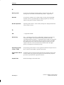
System Function
Menu
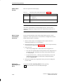
You can select the system function menu from all operating modes. From this
menu, the following functions can be selected:
– RUN-P
– RUN
– STOP
– MRES
The DI/DO status bits are displayed as soon as the system function menu has
been selected:
A–Z
Selecting the
System Function
Menu
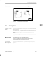
You select the menu by pressing
and
simultaneously.
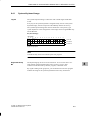
The following menu is displayed:
DI: 00000000 0.7–0.0
00000000 1.7–1.0
➀
➁
DO: 11001000 0.7–0.0
10101000 1.7–1.0
CPU-MODE:
RUN-P
RUN
STOP
MRES
Figure 2-5
2-8
RUN
ESC
System Function Menu with Associated Function Keys
C7-626 / C7-626 DP Control Systems
C79000-G7076-C627-01
Commissioning (Startup)
Selecting the C7
CPU Operating
Modes
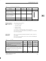
Table 2-1
Mode
RUN-P
You select the individual C7 CPU operating modes as follows:
2
Selecting the C7 CPU Operating Mode
Keys
Explanation
The C7 CPU processes the user program.
Programs and data can be:
S Displayed from the C7 CPU with the programming device
(C7 PG)
S Transferred to the C7 CPU (PG C7)
RUN
The C7 CPU processes the user program.
Programs and data in the C7 CPU can be displayed using the
programming device (C7 PG). The program cannot be loaded or modified. Data cannot
be loaded or modified.
STOP
The C7 CPU is not processing a user program.
Programs can be:
S Displayed from the C7 CPU using the programming device
(C7 PG)
S Transferred to the C7 CPU (PG C7)
Note:
The operating mode STOP is valid only for the C7 CPU. It is not
valid for the C7 OP. Further processing with the C7 OP is possible.
MRES
Memory reset
Resetting the C7 CPU (erase memory, reload user program from flash memory) requires
a special operating sequence of the modes STOP and MRES (see Section 2.3).
If data that are required by the configuration are destroyed during the memory reset, then
a corresponding error message is issued by the C7 OP.
Note:
The MRES position is not a momentary-contact state, which means that the MRES status
persists. For the C7 CPU, the MRES status is only a control mode. When this mode is set
permanently, the C7 CPU does not function properly. This mode must therefore always
be reset prior to exiting the menu with STOP, RUN or RUN-P.
C7-626 / C7-626 DP Control Systems
C79000-G7076-C627-01
2-9
Commissioning (Startup)
DI/DO Status
Display
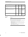
Table 2-2 explains the status display.
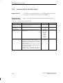
Table 2-3
Explanation of the DI/DO Status Display in Figure 2-5
Point
2
➀
Explanation
Signal state of the DI/DO
S 1 DI/DO set
S 0 DI/DO reset
➁
Pin number from - to (See also pin assignment in Section 2.5 of
Volume 1.)
Note
The values of the DI/DO are read and displayed every 500 ms (unless
otherwise configured). Changes which occur between these times are not
displayed.
Mode Change
Protected by
Password
To prevent uncontrolled C7 CPU mode changes during process control
operations, password protection is activated when a configuration has been
loaded. The procedure is as follows:
1. If the C7 CPU mode is to be changed, the active password level is
checked (password level >=8 is necessary).
2. If the password level is not sufficient, the Login screen for password entry
is automatically displayed (see Section 6.7.1).
3. Enter password
S You can only change the C7 CPU mode with a valid password.
S If no keys are operated within a time specified in the configuration, an
automatic log-off is initiated (reset of the current password level to
0 = lowest level).
S If a password for level = 8 has not yet been allocated, you can only
change the C7 CPU mode by means of the configured superuser
password (default 100).
4. If the password has been recognized as valid, you can now change the
C7 CPU mode.
Exiting the
Operating Mode
Menu
2-10
You exit the C7 CPU Operating Modes menu by pressing
(ESC). The basic screen is then displayed again.
C7-626 / C7-626 DP Control Systems
C79000-G7076-C627-01
Commissioning (Startup)
2.6
Resetting the C7
Overview
If you wish to achieve a neutral state of the C7, you must completely erase
the C7 CPU and possibly also the C7 OP.
Resetting the
C7 OP
The C7 must be switched off. To reset the C7 OP, proceed as follows:
1. Depress and hold the following keys simultaneously
2. Switch on the C7 power supply.
3. The startup of the C7 OP is delayed and the following message displayed:
Press ’DEL’ to erase total intern FLASH!
The following procedure is possible:
– If you confirm this message within the delay time with the DEL key,
the memory of the C7 OP will be completely deleted (configuration
and OP firmware).
– If you do not confirm the message, nothing is deleted, and the C7 OP
will start up as usual and the existing configuration will be started.
If the C7 OP is reset, the configuration can only be loaded via the serial V.24
interface (see Section 2.3).
What Remains
after a Memory
Reset of the
C7 OP?
Resetting the C7 CPU means that the C7 CPU is reinitialized, the current
control program is deleted and any user program found in the flash memory
of the C7 CPU is reloaded.
S Erase with the C7 system function C7 CPU Operating Modes
S Erase with the programming function (see programming device manual)
A reset using the programming device function is only possible when the
C7 CPU is in STOP mode.
C7-626 / C7-626 DP Control Systems
C79000-G7076-C627-01
2-11
2
Commissioning (Startup)
How to Reset the
C7 CPU
The following describes how to clear the C7 CPU with the help of the system
function C7 CPU OperatingModes.
1. Switch on the power supply to the C7 and wait until the start-up tests
have been completed.
The standby message will be displayed.
2
2. Select the system function menu by pressing the keys
A–Z
.
The menu with the C7 CPU Operating Modes RUN-P, RUN, STOP,
MRES will be displayed.
3. Select the STOP function by pressing the corresponding function keys.
The STOP LED lights up.
4. Select the MRES function (memory reset) and wait (approximately three
seconds) until the STOP LED lights up again.
5. Immediately after, the STOP LED lights up again: select STOP with the
corresponding function keys and then MRES a second time.
Result:
– If the STOP LED flashes for approximately three seconds and then
lights up again: everything is O.K.; the C7 CPU has been completely
reset.
– If the STOP LED does not flash, or other indicators light up or flash
(exception: BATF LED): repeat steps 4 and 5; perhaps evaluate the
diagnostic buffer of the C7 using the programming device.
– If the BATF and the SF LEDs on the C7 light up, the back-up battery
is missing. If a back-up battery is indeed fitted, then you must search
the diagnostic buffer of the C7 CPU for additional error entries.
6. In order to be able to continue working, you must set the C7 CPU to
STOP or RUN / RUN-P.
Note
The contents of the flash memory remain (see also Section 3.10).
2-12
C7-626 / C7-626 DP Control Systems
C79000-G7076-C627-01
Commissioning (Startup)
Procedure in the
C7 CPU During
Memory Reset
The STOP LED flashes during the memory reset of the C7 CPU and the
following process is carried out:
1. The C7 CPU erases the entire user program in the work memory and in
the load memory.
2
2. The C7 CPU erases the back-up memory.
3. The C7 CPU tests the hardware.
4. If an application is stored in the integrated flash memory of the C7 CPU,
its contents will be automatically copied into the load memory and
compiled in the work memory (see Section 3.10).
If no application is stored, then the load memory remains empty and the
C7 CPU has the memory content “0”.
What Remains
after Resetting the
C7 CPU ...
After resetting the C7 CPU, the following items remain:
S The contents of the diagnostic buffer
The contents can be displayed using the programming device.
S System diagnostic parameters
S Perhaps a user program loaded from the flash memory with reinitialized
data
S The MPI parameters last set.
C7-626 / C7-626 DP Control Systems
C79000-G7076-C627-01
2-13
Commissioning (Startup)
2
2-14
C7-626 / C7-626 DP Control Systems
C79000-G7076-C627-01
3
Controlling with the C7 CPU
Summary of
Sections
You Will Find
In Section
On Page
3.1
C7 CPU: Overview
3-2
3.2
Programming the C7 CPU
3-3
3.3
Performance Characteristics of the C7 CPU
3-4
3.4
C7 CPU Blocks
3.5
DP Interface of the C7-626 DP
3-10
3.6
C7 CPU Parameters
3-12
3.6.1
Parameter Block “Clock Memory”
3-13
3.6.2
Parameter Block “Start-Up Characteristics”
3-14
3.6.3
Parameter Block “System Diagnostics”
3-15
3.6.4
Parameter Block “Retentive Areas”’
3-16
3.6.5
Parameter Block “Hardware Interrupts”
3-17
3.6.6
Parameter Block “Real-Time Clock”
3-18
3.6.7
Parameter Block “Time-Of-Day Interrupts”
3-19
3.6.8
Parameter Block “Cyclic Interrupts”
3-20
3.6.9
Parameter Block “Cycle Behavior”
3-21
3.6.10
Parameter Block “MPI Addresses”
3-22
3.7
Calculating the Scan Cycle Time and Response Time of the
C7 CPU
3-23
3.7.1
Calculation Example for the Scan Cycle Time
3-30
3.7.2
Calculation Example for the Response Time
3-31
3.7.3
Hardware Interrupt Response Time
3-33
3.7.4
Diagnostic Interrupt Response Time
3-35
3.8
Bus Processing Times in the PROFIBUS-DP Network
3-36
3.8.1
Components of the Response Time with the C7-DP CPU
as DP Master
3-37
3.8.2
Bus Processing Time tDP
3-38
3.9
Test and Reference Data Functions of the C7 CPU
3-39
3.10
Loading / Erasing the C7 CPU Flash Memory
3-42
C7-626 / C7-626 DP Control Systems
C79000-G7076-C627-01
3-6
3-1
Controlling with the C7 CPU
3.1
C7 CPU: Overview
Properties of the
C7-626
The CPU of the C7-626 has the following characteristics:
S 96 Kbyte work memory
S 160 Kbyte integrated load memory RAM
S 512 Kbyte integrated flash memory
S Integrated IM 360
3
S Speed: approximately 0.3 ms per 1000 binary instructions
S Maximum 512 digital I/Os connectable
S Maximum 128 analog I/Os connectable
S Back-up battery
Properties of the
C7 626 DP
The CPU of the C7-626 DP has the following characteristics:
S 96 Kbyte work memory
S 160 Kbyte integrated load RAM memory
S 512 Kbyte integrated flash memory
S Integrated IM 360
S Speed: approximately 0.3 ms per 1000 binary instructions
S Free addressing
S Additional system status lists for DP
S Maximum 1024 digital I/Os connectable
S Maximum 128 analog I/Os connectable
S Back-up battery
3-2
C7-626 / C7-626 DP Control Systems
C79000-G7076-C627-01
Controlling with the C7 CPU
3.2
Programming the C7 CPU
Overview
The user program that controls the process to be visualized on the C7 OP
runs on the C7 CPU.
Required Tools
You require the following tools to develop the user program:
S Programming device/PC with multipoint interface and corresponding
3
cable
S STEP 7 with the appropriate manuals
S C7
Programming
Languages
Two programming languages are currently relevant to the C7 CPU:
S STL: Statement List consists of a series of statements. Each statement in
your program contains instructions which mnemonically represent a
function of the C7 CPU.
S LAD: A Ladder diagram is a graphic programming language that
resembles electrical circuit diagrams.
Other programming languages are, for example, SCL and HiGraph.
C7-626 / C7-626 DP Control Systems
C79000-G7076-C627-01
3-3
Controlling with the C7 CPU
3.3
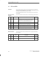
Performance Characteristics of the C7 CPU
Overview
Table 3-1
3
Table 3-1 lists the most significant performance characteristics of the
C7 CPU.
Performance Characteristics of the C7 CPU
Performance
Characteristic
C7 CPU
Integrated
S 160 Kbyte RAM
S 512 Kbyte integrated flash memory
Work memory
96 Kbytes
Load memory
Integrated
Speed
Approx. 0.3 ms per 1000 binary instructions
Digital inputs/outputs
16/16
Analog inputs/outputs
4/1
Universal inputs
DP address space
4
Only C7-626 DP
S 2 Kbytes with SFC 14 “DPRD_DAT” and SFC 15 “DPWR_DAT”
S of which 512 bytes (with load and transfer commands)
Connectable DP slaves
Only C7-626 DP
64
Bit memories
2048
From M0.0 to M255.7
Selectable retentivity;
Preset: 16 retentive memory bytes (from 0 to 15)
Counters
64
From C0 to C63
Selectable retentivity (memory required: 2 bytes/counter);
Preset: 8 retentive counters (from 0 to 7)
Timers
128
From T0 to T127
Selectable retentivity (memory required: 2 bytes/timer);
Preset: no retentive timers
Retentive data area
Max. 8 data areas from one or more data blocks
Maximum of 4096 retentive data bytes
Maximum total of all
retentive data areas
4736 bytes
Clock memory
Memory that can be used in the user program to obtain a clock beat.
Number: 8 (1 memory byte); freely selectable address of a memory byte
Local data
Total 1536 bytes
256 bytes for each priority class
3-4
C7-626 / C7-626 DP Control Systems
C79000-G7076-C627-01
Controlling with the C7 CPU
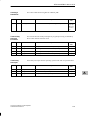
Table 3-1
Performance Characteristics of the C7 CPU
Performance
Characteristic
Process image area
C7 CPU
From 0 to 127
Digital inputs:
from I0.0 to I127.7
Digital outputs:
from Q0.0 to Q127.7
Nesting level
8 for each priority class
3
4 additional within an error OB
Blocks
OBs
14
FBs
128
FCs
128
DBs
127
SDBs
9
SFCs
37 for C7-626 DP = 40
SFBs
Clock
Hardware clock
Run-time meter
C7-626 / C7-626 DP Control Systems
C79000-G7076-C627-01
1
3-5
Controlling with the C7 CPU
3.4
C7 CPU Blocks
Overview
Table 3-2
Table 3-2 lists all blocks that the C7 CPU can process.
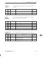
Overview: C7 CPU Blocks
Block
Number
Range
Maximum Size
Comment
OB
14
-
8 Kbytes
A complete list of all possible OBs can be found
at the end of this table.
FB
128
0 - 127
8 Kbytes
-
FC
128
0 - 127
8 Kbytes
-
DB
127
1 - 127
8 Kbytes
SFC
34
-
-
3
0 is reserved
A complete list of all SFCs in the C7 CPU can be
found in Appendix A.
A detailed description can be found in the
reference manual /235/ .
Organization Block
(OB)
The operating system of the C7 CPU is based on event-controlled user
program processing. The following table shows which organization blocks
(OBs) are automatically called up by the operating system for which event.
Description of the
OBs
A detailed description of the various OBs and their users can be found in the
manual /235/.
Size of an OB
An OB can have a maximum size of 8 Kbytes.
OBs for Scan
Cycle and Startup
Table 3-3 lists the OBs which determine the behavior of the C7 CPU during
the scan cycle and startup.
Table 3-3
List of OBs for Scan Cycle and Startup
Scan Cycle and Startup
Scan cycle
Startup (STOP-RUN transition)
OB for Internal and
External Interrupts
Activated OB
Possible Start
Events
Preset Priority of
the OB
OB1
1101H, 1103H
Lowest priority
OB100
1381H, 1382H
-
Table 3-4 lists OBs which determine the behavior of the C7 CPU after
interrupt events.
The priority of the OBs cannot be changed.
3-6
C7-626 / C7-626 DP Control Systems
C79000-G7076-C627-01
Controlling with the C7 CPU
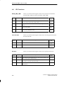
Table 3-4
List with C7 CPU Interrupt Events
Activated OB
Possible Start
Events
Priority of the
OB
Priority
Time-of-day interrupt
OB10
1111H
2
Low
Time-delay interrupt
Range: 1 ms to 60000 ms
(adjustable in 1 ms increments)
OB20
1121H
3
Cyclic interrupt
Range: 1 ms to 60000 ms
(adjustable in 1 ms increments)
(Default value: 100 ms)
OB35
1136H
12
Hardware interrupt
OB40
1141H
16
Diagnostic interrupt
OB82
3842H, 3942H
26
Interrupts (Internal and
External)
Behavior of the C7
CPU with Missing
OB
3
High
The C7 CPU reverts to STOP if a
S Time-of-day interrupt
S Time-delay interrupt
S Hardware interrupt
S Diagnostic interrupt
occurs, but the corresponding OB has not been programmed.
The C7 CPU does not revert to STOP if a cyclic interrupt occurs and OB35
has not been programmed.
OB for Error
Responses
Table 3-5 lists the OBs which determine the behavior of the C7 CPU in an
error situation.
The C7 CPU reverts to STOP if an error occurs, but the corresponding OB
has not been programmed.
Table 3-5
List of OBs
Error
Activated OB
Possible Start
Events
Preset Priority of
the OB
Time error
(for example, initiated by the scan cycle time monitor)
OB80
3501H, 3502H,
3505H, 3507H
26
Power supply error
(for example, missing back-up battery)
OB81
3822H, 3922H
26
One of the following errors has occurred:
OB85
35A1H, 39B1H,
39B2H
26
OB86
38E1H, 39E2H,
26
S Event that triggers OB start (for example, time-delay
interrupt) has occurred but the relevant OB cannot be
executed
S Error during update of the process image
Failure/return of a node in the PROFIBUS-DP network
C7-626 / C7-626 DP Control Systems
C79000-G7076-C627-01
3-7
Controlling with the C7 CPU
Table 3-5
List of OBs, continued
Error
Activated OB
Possible Start
Events
Preset Priority of
the OB
OB87
35E1H, 35E2H,
35E6H
26
Programming error
(for example, the addressed timer does not exist)
OB121
2521H, 2522H,
2523H, 2524H,
2525H, 2526H,
2527H, 2528H,
2529H, 2530H,
2531H, 2532H,
2533H, 2534H,
2535H, 253AH,
253CH, 253EH
The same priority
as the OB in
which the error
has occurred
Error during direct I/O access (defective or missing module)
OB122
2944H, 2945H
The same priority
as the OB in
which the error
has occurred
Communications error
S Wrong message frame identifier when receiving global
data
S The data block for the global data status is not available
or too short
3
OB121 and
OB122
Please note the following feature of the C7 CPU in connection with OB121
and OB122:
Note
Please note the following feature for OB121 and OB122:
The C7 CPU enters the value “0” in the following temporary variables of the
variable declaration table in the local data of the OBs:
S Byte no. 4: OB121_BLK_TYPE or OB122_BLK_TYPE (type of block
where error occurred)
S Byte nos. 8 and 9: OB121_BLK_NUM or OB122_BLK_NUM (number
of block where error occurred)
S Byte nos. 10 and 11: OB121_PRG_ADDR or OB122_PRG_ADDR
(address in block where error occurred)
3-8
C7-626 / C7-626 DP Control Systems
C79000-G7076-C627-01
Controlling with the C7 CPU
CPU Behavior with
Missing Error OB
If you do not program an error OB, the C7 CPU behaves as follows:
C7 CPU goes to STOP mode with
missing...
OB80
(time error)
OB85
(program execution error)
OB86
(station failure in
PROFIBUS-DP network)
OB87
(communication error)
OB121
(programming error)
OB122
(direct I/O access error)
C7-626 / C7-626 DP Control Systems
C79000-G7076-C627-01
C7 CPU remains in RUN mode with
missing...
OB81
(power supply error)
3
3-9
Controlling with the C7 CPU
3.5
3
DP Interface of the C7-626 DP
Overview
This section describes all the data which define the C7-626 DP as a DP
master. You need to know these data in order to configure a PROFIBUS-DP
network with the C7-626 DP.
Reference
Information
You will find descriptions and information about the design and
configuration of a PROFIBUS-DP network and diagnostics on the
PROFIBUS-DP network in the STEP 7 on-line help and in the STEP 7
documentation.
C7-626 DP as a
DP Master
Table 3-6 contains important specifications for operating the C7-626 DP as a
DP master:
Table 3-6
Important Specifications for Operating the C7-626 DP as a DP Master
Specifications
Transmission rates
C7-626 DP as a DP Master
9.6 Kbps
1.5 Mbps
19.2 Kbps
3 Mbps
93.75 Kbps
6 Mbps
187.5 Kbps
12 Mbps
500 Kbps
The following DP stations (DP slaves)
can be connected:
ET 200
DP/ASI link
PLC 95 DP (DP slave)
S5-115U to 155U with IM308C
(as DP slave)
Field devices to DIN E 19245 Part 3
Number of addressable slaves
3-10
64
C7-626 / C7-626 DP Control Systems
C79000-G7076-C627-01
Controlling with the C7 CPU
Address Space of
the C7-CPU DP
Table 3-7 lists the address spaces and their size for operating the C7-626 DP
as a DP master:
Table 3-7
Address Spaces and their Size for Operating the C7-626 DP as a
DP Master
Size
Address Space User Data
Unassigned addresses
Bytes 0 to 1023
in normal I/O area (P)
Up to 512 bytes via load and transfer
instructions
in process image
Bytes 0 to 128
Total on DP
2 Kbytes with
3
SFC14 “DPRD_DAT” readable and
SFC15 “DPWR_DAT” writeable
of which 512 bytes via load and transfer
instructions
Size of an area for consistent user data
Up to 32 bytes
User data of a station (node)
Input:
Output:
C7-626 / C7-626 DP Control Systems
C79000-G7076-C627-01
122 bytes
122 bytes
3-11
Controlling with the C7 CPU
3.6
C7 CPU Parameters
Configurable
Characteristics of
the C7 CPU
The characteristics and behavior of the C7 CPU can be assigned parameters.
Parameter blocks of the C7 CPU:
S Clock memory
S Start-up characteristics
S System diagnostics
3
S Retentive areas
S Hardware interrupt
S Real-time clock
S Time-of-day interrupt
S Cyclic interrupt
S Cycle behavior
S MPI station addresses
Tool for Parameter
Assignment
The tool that you use to assign the parameters to the C7 CPU is the STEP 7
function Hardware Configuration. Working with Hardware Configuration is
described in manual /231/.
When Does the
C7 CPU “Accept”
the Parameters?
The C7 CPU accepts the selected parameters
S After power on
S After the parameters have been transferred on-line and error-free to the
C7 CPU in STOP mode.
S After erasing the C7 CPU (see Section 2.6)
If an SDB0 is available in the integrated flash memory, then the stored
parameters will be loaded with the exception of the MPI parameters. If no
SDB0 is present in the flash memory, then the standard parameters of
SDB2 will be set.
!
3-12
Caution
If, after the last storage of the program in the flash memory of the C7,
additional parameters are modified (in the RAM), these will be lost the next
time the memory is reset, with the exception of the MPI parameters.
C7-626 / C7-626 DP Control Systems
C79000-G7076-C627-01
Controlling with the C7 CPU
3.6.1
Parameter Block “Clock Memory”
Definition: Clock
Memory
Clock memories are memories which periodically change their binary states
at regular intervals in a pulse-pause ratio 1:1. Eight fixed frequencies are
defined for the C7; these can be allocated to any memory byte. The period
time can be found in Figure 3-1.
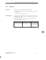
Clock Period Time
Figure 3-1 shows the period times and the corresponding clock frequencies
generated by the “clock memory byte”.
Clock memory byte
Bit
Period time and corresponding frequency
7 6 5 4 3 2 1 0
0.1 seconds corresponding to 10 Hz
0.2 seconds corresponding to 5 Hz (lamp flicker)
0.4 seconds corresponding to 2.5 Hz (fast lamp flash)
0.5 seconds corresponding to 2 Hz
0.8 seconds corresponding to 1.25 Hz (lamp flash)
1.0 seconds corresponding to 1 Hz
1.6 seconds corresponding to 0.625 Hz (slow lamp flash)
2 seconds corresponding to 0.5 Hz
Figure 3-1
Parameter Block
“Clock Memory”
Table 3-8
Clock Period Times in the “Clock Memory Byte”
Table 3-8 lists the parameters of the parameter block “Clock Memory”.
Parameter Block “Clock Memory”
Explanation
Parameter
Clock memory
For “Clock memory = yes”, a memory
byte must be defined
Memory byte
Memory byte that should be used for the
“clock memory byte”
C7-626 / C7-626 DP Control Systems
C79000-G7076-C627-01
C7 CPU
Value Range
Default Setting
Yes/No
No
From 0 to 255
-
3-13
3
Controlling with the C7 CPU
3.6.2
Parameter Block “Start-Up Characteristics”
Parameter Block
“Start-Up
Characteristics”
Table 3-9
Parameter Block “Start-Up Characteristics”
Parameter
3
Table 3-9 lists the parameters of the parameter block “Start-Up
Characteristics”.
Explanation
Value Range
Default Setting
Yes/No
Yes
Only “Complete restart” can be set for the
C7 CPU.
Restart
Restart
Maximum time for the “distribution” of the
parameters to the modules within the rack
From 1 to 10,000
100
Self-test after power on and For “Self-test on cold restart = yes”, the C7 CPU
reset
tests its internal RAM after every power on
Startup
S Manual
Restart
S Automatic
Module time limits
S Parameter assignment
during startup (in ms)
Module time limits
S Ready message after
power on (in ms)
Tip:
3-14
Maximum time for the ready message of all
From 1 to 65,000
modules after power on
If the modules do not transmit a ready message
to the C7 CPU within this time, then the C7 CPU
reverts to STOP.
65000
You should assign the highest values to the parameters for the “module time
limits” if you are not sure of the required times in the C7.
C7-626 / C7-626 DP Control Systems
C79000-G7076-C627-01
Controlling with the C7 CPU
3.6.3
Parameter Block “System Diagnostics”
Definition:
System
Diagnostics
System diagnostics perform the acquisition, evaluation and reporting of an
error within the programmable controller. The wiring to the process is also
included in the system diagnostics so that, for example, “wire breaks” can be
recognized by the system diagnostics.
Example
Examples of errors that can be identified, evaluated and reported by the
system diagnostics are:
3
S Errors in the user program
S Failure of hardware modules
S Breaks in wiring to transducers
Parameter Block
“System
Diagnostics”
Table 3-10
Table 3-10 lists the parameters of the parameter block “System Diagnostics”.
Parameter Block “System Diagnostics”
Explanation
Value Range
Default Setting
Extended diagnostic
buffer entries
For “Extended diagnostics buffer entries = yes”,
the C7 CPU enters not only the error events into
the diagnostic buffer but also all OB calls.
Yes/No
No
Transmission of
diagnostic messages
after reversion to the
STOP mode
For “Transmission of diagnostics messages.... =
yes”, the C7 CPU transmits the cause of STOP
via the multipoint interface to the display system
(programming device, OP). This diagnostic
message is the “newest” entry in the diagnostic
buffer.
Yes/No
Yes
Parameter
Undetected Errors
Errors that occur in the process, that is outside the automation system, are not
detected by the system diagnostics. Such errors are for example “motor
failure”. These errors fall within the area of the process error diagnostics.
C7-626 / C7-626 DP Control Systems
C79000-G7076-C627-01
3-15
Controlling with the C7 CPU
3.6.4
Parameter Block “Retentive Areas”’
Definition:
Retentivity
A memory area is retentive when its contents are retained even after a power
failure and a transition from STOP to RUN. The non-retentive areas for the
bit memory, timers and counters are reset after a power failure and after a
transition STOP - RUN.
The following can be retentive:
S Bit memory
3
S Timers
S Counters
S Data areas
Retentivity Without
Battery Backup
Areas that you declare to be “retentive areas” in the parameter block will be
preserved without a back-up battery after a power failure and after a
transition from STOP to RUN. The boundary defined for the retentive and
non-retentive areas is not influenced by the use of a back-up battery in the
C7.
Note
The C7 must always be supplied with a back-up battery.
Retentivity With
Data Blocks
3-16
All data blocks are retentive. Because of their retentive nature, any new
settings made in the data blocks are ineffective while the back-up battery is
supplying enough power.
C7-626 / C7-626 DP Control Systems
C79000-G7076-C627-01
Controlling with the C7 CPU
Parameter Block
“Retentive Areas”
Table 3-11
Table 3-11 lists the parameters of the parameter block “Retentive Areas”.
The retentive area for all areas (bit memory, timers, counters and data bytes)
may not be larger than for the sum of all the parameters listed in Table 3-11.
Parameter Block “Retentive Areas”
Parameter
Explanation
Value Range
C7
Default
Setting
Memory bytes
The parameter value entry is the number of retentive
memory bytes from memory byte 0
0 to 256
16
Timers
The parameter value entry is the number of retentive S7
timers from timer 0 (space required: 2 bytes/timer)
0 to 128
0
Counters
The parameter value entry is the number of retentive S7
counters from counter 0 (space required: 2 bytes/counter)
0 to 64
8
Data areas
Max. 8 data areas may be retentive with a maximum of
4096 bytes. The start address of the data area + the
number of data bytes may not exceed 8191.
S Data block number
S Number of bytes
S From 1
3
S 1
to 127
S From 0
S 0
to 4096
S Byte address (start
S From 0
address of the data
area)
to 8191
Sum of all retentive data
3.6.5
S 0
4736 bytes
Parameter Block “Hardware Interrupts”
Parameter Block
“Hardware
Interrupts”
Table 3-12
Table 3-12 lists the parameters of the parameter block “Hardware Interrupts”.
The priority of the hardware interrupt OB40 cannot be altered.
Parameter Block “Hardware Interrupts”
Explanation
Parameter
Priority OB40
The priority of OB40 cannot be altered.
C7-626 / C7-626 DP Control Systems
C79000-G7076-C627-01
Value Range
Default Setting
16
16
3-17
Controlling with the C7 CPU
3.6.6
3
Parameter Block “Real-Time Clock”
Setting the Time
You set the C7 CPU clock using STEP 7 or via the SFC0 “SET_CLK” in the
user program (see Appendix A and reference manual /235/).
Parameter Block
“Real-Time Clock”
Table 3-13 lists the parameters of the parameter block “Real-Time Clock”.
Table 3-13
Parameter Block “Real-Time Clock”
Explanation
Parameter
Synchronization:
on C bus
The synchronization of the real-time clock is
performed via the C bus.
Synchronization:
on the MPI
Not possible
Synchronization:
interval
Interval during which the real-time clock is
synchronized.
Correction factor
A deviation of the real-time clock is compensated
with the correction factor within 24 hours.
Example: if the real-time clock is slow by 4 ms
after 24 hours, then you must set a correction
factor of “+4 ms”.
Example: If the real-time clock is two seconds
slow after seven days, the correction factor is to
be calculated as follows:
2 seconds : 7 days = 286 ms/day; consequently,
you have to set a correction factor of +286.
3-18
Value Range
Default Setting
None as master
None
None
None
None
Seconds
10 seconds
Minute
10 minutes
Hour
12 hours
24 hours
None
From - 10000 to
+ 10000
0
C7-626 / C7-626 DP Control Systems
C79000-G7076-C627-01
Controlling with the C7 CPU
3.6.7
Parameter Block “Time-Of-Day Interrupts”
Overview
The C7 CPU can trigger time-of-day interrupts which you can activate and
assign parameters to via the parameter block “Time-Of-Day Interrupts”.
Priority
The priority of OB10 is fixed at 2. You cannot change this value.
Parameter Block
“Time-Of-Day
Interrupts”
Table 3-14 lists the parameters of the parameter block “Time-Of-Day
Interrupts”.
Table 3-14
3
Parameter Block “Time-Of-Day Interrupts”
Explanation
Value Range
Default Setting
Yes/No
No
Here you set the execution intervals in which the
time-of-day interrupt should be triggered. The
execution interval refers to the start date and the
start time setting.
None
Once only
Every minute
Every hour
Every day
Every week
Every month
Every year
None
Start date OB10
The start date on which the time-of-day interrupt
should be triggered.
-
1994-01-01
Start time OB10
The start time at which the time-of-day interrupt
should be triggered. The start time can only be
entered in hours and minutes.
-
00:00:00
Parameter
Active OB10
Activation of OB10
Execution OB10
C7-626 / C7-626 DP Control Systems
C79000-G7076-C627-01
3-19
Controlling with the C7 CPU
3.6.8
3
Parameter Block “Cyclic Interrupts”
Overview
A cyclic interrupt is a periodic signal that the C7 CPU generates internally
and leads to the automatic call-up of a “cyclic interrupt OB” (OB35).
Priority
The priority of OB35 is fixed at 12. You cannot change this value.
Parameter Block
“Cyclic Interrupts”
Table 3-15 lists the parameters of the parameter block “Cyclic Interrupts”.
Table 3-15
Parameter Block “Cyclic Interrupts”
Parameter
Periodicity of OB35
(in ms)
3-20
Explanation
Call-up interval of OB35
Value Range
Default Setting
From 1
to 60000
100
C7-626 / C7-626 DP Control Systems
C79000-G7076-C627-01
Controlling with the C7 CPU
3.6.9
Parameter Block “Cycle Behavior”
Parameter Block
“Cycle Behavior”
Table 3-16
Table 3-16 list the parameters of the parameter block “Cycle Behavior”.
Parameter Block “Cycle Behavior”
Parameter
Explanation
p
Value
Range
R
Default
S i
Setting
Cycle loading due to communication To limit the extent of “slowing down” program
processing due to communications processes,
(via the MPI) (in %)
you can define the maximum percentage of cycle
loading. The communication between C7 CPU
and programming device or between
communicating C7 CPUs can slow down due to
the cycle loading limit. Operating system
services such as the collection and provision of
data for the communication will not be
influenced.
Functions that require continuous reading of data
“slow down” program execution irrespective of
the value set for this parameter. Example: block
status, displaying system data (STEP 7).
From 5
to 50
20
Maximum scan cycle time (in ms)
From 1
to 6000
150
From 0
to 65000
0
If the scan cycle time exceeds the “maximum
scan cycle time”, then the C7 CPU reverts to
STOP mode if no OB80 is loaded for error
handling. The maximum scan cycle time can be
exceeded due to:
S communications processes
S accumulation of interrupt events
S errors in the user program (for example,
“continuous loops”)
Cycle loading due to self-test (in s)
C7-626 / C7-626 DP Control Systems
C79000-G7076-C627-01
For “Cyclic self-test 0”, the C7 CPU tests its
internal RAM during the program cycle. This
self-test consumes cycle time. You can define the
time by which the program cycle may be
lengthened in multiples of 10 s (“0” = no cyclic
self-test).
3-21
3
Controlling with the C7 CPU
3.6.10
Parameter Block “MPI Addresses”
Multipoint
Interface (MPI)
The characteristics of the multipoint interface (MPI) of the C7 CPU can be
assigned parameters with the parameter block “MPI addresses”. You need
only process this parameter block if several C7 or S7/M7 devices are
networked via the multipoint interface.
Values after
Memory Reset
The parameters of the parameter block “MPI Addresses” have a special
feature: the parameter values are preserved even after a memory reset.
Reason: the communications ability of an “erased” C7 CPU must be
preserved even after a memory reset.
C7 MPI Addresses
The C7 occupies two MPI addresses:
3
S One for the C7 CPU (default address 2)
S One for C7 OP (default address 1)
Parameter Block
“MPI Addresses”
Table 3-17
Table 3-17 lists the parameters of the parameter block “MPI Addresses”.
Parameter Block “MPI Addresses”
Parameter
Highest MPI address
Explanation
Value Range
Default
Setting
The definition of the highest MPI address in the
network is necessary in order that:
15
15
31
S Every (network) station can be addressed
S The communications process operates
63
effectively
126
Note: assign only as many MPI addresses as are
necessary. You will then reduce the
communication times.
The “highest MPI address” must be the same for
all MPI nodes.
C7 CPU MPI address
Each station that is networked via the MPI must
possess an address. The specified address may
only be allocated once in the network.
The C7 OP has its own MPI address
(default = 1).
From 2 to 126
2
1
Note
The MPI is the only communications interface of the C7. Parameters should
only be modified with utmost care.
3-22
C7-626 / C7-626 DP Control Systems
C79000-G7076-C627-01
Controlling with the C7 CPU
3.7
Calculating the Scan Cycle Time and Response Time of the C7 CPU
Overview
This section explains how the scan cycle and response times of a user
program are structured.
Use the programming device to read the scan cycle time of the user program
on the C7 CPU (see programming manual /280/).
An example is used to show you how to calculate the scan cycle time.
The response time is of greater interest, however. This section includes a
detailed description of how to calculate the response time. If you use the
C7-DP CPU as a master in the PROFIBUS-DP network, you must also take
into account bus processing times.
Definition:
Scan Cycle Time
The scan cycle time is the time that passes during a program cycle.
Elements of the
Scan Cycle Time
The scan cycle time comprises the following elements:
S Process-image transfer time (PII and PIQ)
S Operating system execution time
S User program execution time
S Communication via the multipoint interface
Figure 3-2 shows the elements of the scan cycle time.
PII
Operating
system
Can be interrupted
by various interrupts
User program
PIQ
Figure 3-2
C7-626 / C7-626 DP Control Systems
C79000-G7076-C627-01
Elements of the Scan Cycle Time
3-23
3
Controlling with the C7 CPU
Definition:
Response Time
The response time is the time that elapses between the recognition of an
input signal and the change to the associated output signal.
Factors
The response time is dependent upon the following factors:
S Process-image transfer time
S Operating system time
S User program execution time
S Communication via the MPI
3
S Input and output delay times
S Additional bus processing times in the PROFIBUS-DP network
(only C7 DP CPU).
Variation Range
The actual response time lies between the shortest and the longest response
time. During the configuration of your system, you must always assume the
longest response time.
The shortest and longest response times will be considered below, so that you
can form a picture of the variation range of the response time.
3-24
C7-626 / C7-626 DP Control Systems
C79000-G7076-C627-01
Controlling with the C7 CPU
Shortest Response
Time
Figure 3-3 illustrates the conditions for the shortest response time.
Bus processing times in the
PROFIBUS-DP network
PIQ
PII
The state of the observed input changes
immediately before reading the PII. The
change in the input signal will still be
considered in the PII.
3
Response time
Operating
system
User program
The change in the input signal will be
processed here by the user program.
PIQ
The response of the user program to the
change in the input signal is sent to the
outputs here.
PII
Operating
system
Bus processing times in the
PROFIBUS-DP network
Figure 3-3
C7-626 / C7-626 DP Control Systems
C79000-G7076-C627-01
Shortest Response Time
3-25
Controlling with the C7 CPU
Calculation
The (shortest) response time can be calculated as follows:
S 1 x process input image transfer time +
S 1 x operating system execution time +
S 1 x program execution time +
S 1 x process output image transfer time +
S Processing time for S7 timers+
S Input and output delay times
3
The input delays are not marked in the diagram. Depending on the module,
however, you have to take into account the following delay times:
S For digital inputs: input delay time
S For digital outputs: negligible delay times
S For analog inputs: scan cycle time of the analog input
S For analog outputs: response time of the analog output
3-26
C7-626 / C7-626 DP Control Systems
C79000-G7076-C627-01
Controlling with the C7 CPU
Longest Response
Time
Figure 3-4 illustrates the conditions for the longest response time:
Bus processing times in the
PROFIBUS-DP network
PIQ
The state of the observed input changes
while it is being read by the PII. The change
in the input signal will not appear in the PII.
PII
3
Operating
system
User program
Response time
PIQ
The change in the input signal is
written into the PII.
PII
Operating
system
User program
The change in the input signal will be
processed here by the user program.
PIQ
The response of the user program to the
change in the input signal will be transferred
to the outputs here.
PII
Operating
system
Bus processing times in the
PROFIBUS-DP network
Figure 3-4
C7-626 / C7-626 DP Control Systems
C79000-G7076-C627-01
Longest Response Time
3-27
Controlling with the C7 CPU
Calculation
The (longest) response time can be calculated as follows:
S 2 x process input image transfer time +
S 2 x process output image transfer time +
S 2 x operating system execution time +
S 2 x program execution time +
S Processing time for S7 timers +
S Input and output delay times
3
The input delays are not marked in the diagram. Depending on the module,
however, you have to take into account the following delay times:
S For digital inputs: input delay time
S For digital outputs: negligible delay times
S For analog inputs: scan cycle time of the analog input
S For analog outputs: response time of the analog output
Extending the
Scan Cycle Time
As a rule, you should remember that the scan cycle time of a user program
will be increased by:
S Time-controlled processing
S Hardware interrupt processing
S Diagnostics and error processing
S Communication via the multipoint interface
Reducing the
Response Time
3-28
You will achieve faster response times by means of direct access to the I/Os
in the user program, for example, with L PIB or T PQW. This method helps
you avoid prolonged scan cycle times, as described in Figure 3-4.
C7-626 / C7-626 DP Control Systems
C79000-G7076-C627-01
Controlling with the C7 CPU
Operating System
Execution Time
The operating system execution time is caused by various sequences in the
C7 CPU.
System Execution
Times
Table 3-18 lists all times relevant for determining the operating system
execution times of the C7 CPU.
Table 3-18
Operating System Execution Times of the C7 CPU
C7 CPU
Task
3
Cycle control
Approximately 870 s
Communication via the multipoint interface
Block functions (load/delete/copy) extend the cycle by
up to 10 %. Communication via the MPI may load the
cycle by up to 50 %, depending on the parameter
assignment in STEP 7 (see Section 3.6.9).
Updating the S7 timers
7 s x number of timers currently running
C7 CPU self-test
From 0 to 65,000 s; depending on parameter
assignment (see Section 3.6.9)
Rack monitoring
Per rack: 50 s
Process Image
Update
Table 3-19
Table 3-19 contains the C7 CPU times that are applicable to the process
image update. The quoted figures are “ideal values”, which can be increased
by interrupts or communications via the multipoint interface of the C7 CPU.
Process Image Update of the C7 CPU
Process Image Update Times
I/O Configuration
1 C7 (16 bytes)
PII:
approx. 0.3 ms
PIQ: approx.0.27 ms
C7 + 3 racks (64 bytes)
PII:
approx. 1.4 ms
PIQ: approx. 1.2 ms
C7 + 3 racks (128 bytes = max. configuration)
PII:
approx. 1.7 ms
PIQ: approx. 1.4 ms
C7-626 / C7-626 DP Control Systems
C79000-G7076-C627-01
3-29
Controlling with the C7 CPU
3.7.1
Calculation Example for the Scan Cycle Time
Components of the
Scan Cycle Time
To recap: The scan cycle time consists of the following:
S Process-image transfer time
S Operating system execution time
S User program execution time
S Processing time for S7 timers
3
Example
The user program in the C7 CPU has an execution time of 1.5 ms. Your user
program uses four S7 timers.
In the parameter assignment of the C7 CPU, you have deactivated the
C7 CPU self-test and, since the C7 CPU is a stand-alone unit, the cycle is not
loaded with communication tasks.
Calculation
In the example, the scan cycle time is calculated from the following times:
S Process image transfer time
– Process-image input table: approx. 0.2 ms
– Process-image output table: approx 0.15 ms
S Operating system execution time
– Cycle control: approx. 0.87 ms
– Rack monitoring: approx. 0.05 ms
S User program execution time: approx. 1.5 ms
S Processing time for S7 timers
For four S7 timers, the single update takes
4 x 7 us = 28 us = 0.03 ms. Adding the process-image transfer time, the
operating system execution time and the user program execution time
yields the time interval:
0.2 ms + 0.15 ms + 0.87 ms + 0.05 ms + 1.5 ms = 2.77 ms. This time
interval prolongs the execution time of the S7 timers:
ǒ
Ǔ
Execution time of S7 timers + 1 ) 2.77 ms
10 ms
0.03 ms + 0.04 ms
The scan cycle time is the sum of the times listed:
Cycle time = 0.2 ms + 0.15 ms + 0.87 ms + 0.04 ms + 1.5 ms [ 2.8 ms.
3-30
C7-626 / C7-626 DP Control Systems
C79000-G7076-C627-01
Controlling with the C7 CPU
3.7.2
Calculation Example for the Response Time
Response Time
To recap, the response time is a total of :
S 2 x process input image transfer time +
S 2 x process output image transfer time +
S 2 x operating system execution time +
S 2 x program execution time +
S Processing time for S7 timers +
3
S Input and output delay times
Example
It is based on a C7 control system including I/O.
CPU Parameters
These are based on the data from the calculation example for the scan cycle
time.
Calculation
The response time for the example is as follows:
S Process-image transfer time
– Process input image (PII): approx. 0.85 ms
– Process output image (PIQ): approx. 0.6 ms
S Operating system execution time
– Cycle control: 0.87 ms
– Rack monitoring: approx. 0.1 ms
– CPU self-test: 0.5 ms
S User program execution time: 2.6 ms
S 1st subtotal: As a time basis for calculating the
– Execution time for the timers and the
– Cycle load due to communication
the sum of all the times listed below is valid:
2 x 0.8 ms
(Process input image transfer time)
+ 2 x 0.6 ms
(Process output image transfer time)
+ 2 x (0.87 ms+0.1 ms+0.5 ms) (Operating system execution time)
+ 2 x 2.6 ms
[11 ms
C7-626 / C7-626 DP Control Systems
C79000-G7076-C627-01
(User program execution time)
3-31
Controlling with the C7 CPU
S Execution time for the S7 timers
For 32 S7 timers, the single update takes 32 7 s [ 0.22 ms.
The execution time for the S7 timers is calculated as follows:
ǒ
Ǔ
Execution time of S7 timers + 1 ) 4.04 ms
10 ms
0.03 ms [ 0.04 ms
S Cycle load due to communication 20 %
The time base is the 11 ms calculated above. 20% of this is 2.2 ms.
3
S 2nd subtotal: The response time not including the delay times of the
inputs and outputs is calculated from the total of:
11 ms
+ 0.5 ms
+ 2.2 ms
= 13.7 ms[14 ms
(Result of the first subtotal)
(Execution time for S7 timers)
(Cycle load due to communication)
S Input and output delay times
– The digital input SM321; DI 16 x 24 VDC has an input delay of max.
4.8 ms per channel
– The delay time of the digital output of the C7 can be neglected.
– The analog input of the C7 has a resolution of 12 bits. The conversion
time per channel is approximately 0.5 ms. All four channels are
supposed to be active. Calibration measurement must be enabled. The
cycle time is thus 2.5 ms.
– The analog output of the C7 has a conversion time of 0.8 ms per
channel. A settling time for the ohmic load of 0.1 ms must be added to
this. This yields a response time for the analog output of 0.9 ms.
S Response times with delay times of the inputs and outputs:
S Case 1: An output channel is enabled when a digital input signal is read
in. The response time is:
Response time = 4.8 ms + 5 ms = 9.8 ms [ 10 ms
S Case 2: An analog value is read in and an analog value is output. The
response time is:
Response time = 2.5 ms + 5 ms + 0.9 ms = 3.9 ms [ 4 ms
3-32
C7-626 / C7-626 DP Control Systems
C79000-G7076-C627-01
Controlling with the C7 CPU
3.7.3
Hardware Interrupt Response Time
Hardware Interrupt
Response Time
The hardware interrupt response time is the time that elapses between the
first occurrence of a hardware interrupt signal and the calling of the first
instruction in the hardware interrupt OB (OB40).
In general, higher-priority interrupts take precedence. That means the
hardware interrupt response time is increased by the program execution time
of the higher-priority hardware interrupt OBs and hardware interrupt OBs of
the same priority which have not yet been processed.
Calculation
The hardware interrupt response time is calculated as follows:
Hardware interrupt response time = hardware interrupt response time of the
C7 CPU + hardware interrupt response time of the signal module.
C7 CPU
The hardware interrupt response time of the C7 CPU is approx. 1.1 ms.
Signal Modules
The hardware interrupt response time of the signal modules is calculated as
follows:
S Digital input modules
Hardware interrupt response time = Internal interrupt preparation time +
input delay
The times are listed in the data sheet for the respective digital input
module
S Analog input modules
Hardware interrupt response time = Internal interrupt preparation time +
conversion time
The internal interrupt preparation time of the analog input modules can be
neglected. Please refer to the data sheet of the respective analog input
module for conversion times.
Interrupt Handling
Hardware interrupt processing begins when the hardware interrupt OB
(OB40) is called. Higher-priority interrupts cause the hardware interrupt
processing to be interrupted. Direct access to the I/O is made when the
instruction is processed. When the hardware interrupt processing has
finished, either cyclic program execution continues or further interrupt OBs
of higher priority or the same priority are called up and executed.
Calculation
Example
To recap, the hardware interrupt response time consists of:
S The hardware interrupt response time of the CPU
S The hardware interrupt response time of the signal module.
Example: In the example, the C7 I/O is to be used exclusively.
C7-626 / C7-626 DP Control Systems
C79000-G7076-C627-01
3-33
3
Controlling with the C7 CPU
Calculation
For the example, the hardware interrupt response time is calculated from the
following times:
S Hardware interrupt response time of the C7 CPU: approx. 1.1 ms
S Hardware interrupt response time of the module:
– Internal interrupt preparation time: 0.2 ms
– Input delay:
0.1 ms
The hardware interrupt response time is calculated from the sum of the times
below:
3
Hardware interrupt response time = 1.1 ms + 0.2 ms + 0.1 ms =
approx. 1.4 ms.
This hardware interrupt response time elapses from the time a signal is
present at the digital input until the first instruction in OB40 is processed.
3-34
C7-626 / C7-626 DP Control Systems
C79000-G7076-C627-01
Controlling with the C7 CPU
3.7.4
Diagnostic Interrupt Response Time
Diagnostic
Interrupt
Response Time
The diagnostic interrupt response time is the time that elapses between the
first occurrence of a diagnostic interrupt signal and the calling of the first
instruction in the diagnostic interrupt OB (OB82).
In general, higher-priority interrupts take precedence. That means the
diagnostic interrupt response time is increased by the program execution time
of the higher-priority interrupt OBs and interrupt OBs of the same priority
which have not yet been processed.
Calculation
The diagnostic interrupt response time is calculated as follows:
Diagnostic interrupt response time = Diagnostic interrupt response time of
the C7 CPU + diagnostic interrupt response time of the signal module.
For C7: 0.6 ms
C7 CPU
The diagnostic interrupt response time of the C7 CPU is approximately
1.3 ms.
Calculation
Example
1.3ms + 0.6ms = 1.9ms [2 ms
C7-626 / C7-626 DP Control Systems
C79000-G7076-C627-01
3-35
3
Controlling with the C7 CPU
3.8
Bus Processing Times in the PROFIBUS-DP Network
Introduction
In a PROFIBUS-DP network, the response times are composed of several
components:
S The response time of the DP master
S The bus processing time in the PROFIBUS-DP network
S The response time of the DP slave
3
Overview
This section describes the main information about the bus processing times in
the PROFIBUS-DP network.
The description in this section refers to the operation of the C7-DP CPU as a
master in the PROFIBUS-DP network.
The bus processing times are always dependent on the number of slaves, the
transmission rate and the number of RS 485 repeaters.
You can use a programming device to display the bus processing time in your
PROFIBUS-DP network (see STEP 7 documentation). An example is used to
show you how to estimate the bus processing time without a programming
device.
To calculate the response time of the C7-DP CPU as a master, please read
Sections 3.7 to 3.7.4.
To calculate the response times of a DP slave, please read the documentation
for the corresponding DP slave.
3-36
C7-626 / C7-626 DP Control Systems
C79000-G7076-C627-01
Controlling with the C7 CPU
3.8.1
Components of the Response Time with the C7-DP CPU as
DP Master
Response Times
within PROFIBUS
DP
Figure 3-5 shows the components of the response time in a PROFIBUS-DP
network. These times together produce the average response time which
elapses between a change in state on an input and the associated change in
state on an output:
3
C7-DP CPU as DP master
➁
➁
①
➂
➀ User program execution time in C7-DP CPU
➁ Response time of the DP slave
➂ Bus processing time
Figure 3-5
Description
➂
Response Times within the PROFIBUS-DP Network
Table 3-20 shows where you can find a description of the various
components of the response times.
Table 3-20
Components of the Response Time in the PROFIBUS-DP Network
No.
Component of Response Time
Description
➀
User program execution time in the
C7-DP CPU
See Sections 3.7 to 3.7.4
➁
Response time of the DP slave
In the documentation for the DP
slave
➂
Bus processing time
In this section
C7-626 / C7-626 DP Control Systems
C79000-G7076-C627-01
3-37
Controlling with the C7 CPU
3.8.2
Bus Processing Time tDP
Definition
The bus processing time is the time taken by the DP master to address all the
DP slaves assigned to it once only.
Calculation Using
STEP 7
If you have configured your PROFIBUS-DP network using STEP 7, STEP 7
will calculate the typical bus processing time to be expected. You can display
the bus processing time of your configuration on the programming device
(see STEP 7 User Manual).
3
An overview of the bus processing time is provided in Figure 3-6. In this
example, it is assumed that each DP slave has an average of 4 bytes of data.
Bus processing time
7 ms
Transmission rate:1.5MBit/s
6 ms
5 ms
4 ms
3 ms
2 ms
Transmission rate: 12 MBit/s
1 ms
1
Figure 3-6
Several
DP Masters
3-38
2
4
8
16
32
Number of DP slaves
Overview of the Bus Processing Time on PROFIBUS-DP at 1.5 MBit/s
and 12 MBit/s
If you operate a PROFIBUS-DP network with several masters, you must
allow for the bus processing time for each master; that is,
Total bus processing time = Bus processing time Number of masters
C7-626 / C7-626 DP Control Systems
C79000-G7076-C627-01
Controlling with the C7 CPU
3.9
Test and Reference Data Functions of the C7 CPU
Overview
The C7 CPU offers the option of scanning the status of the C7 CPU and its
associated signal modules by means of a series of test and reference data
functions. This enables you to obtain information on the following:
S The current layout of the C7
S The current parameter assignment
S The current states
3
S The current sequences
in the C7 CPU and the associated signal modules.
You can also change process variables independently of the user program.
Description of the
Test and Reference
Data Functions
The test and reference data functions can only be executed using the STEP 7
software. The description of the test and reference data functions can be
found in the appropriate chapters of the manual /231/.
List of Test and
Reference Data
Functions
Table 3-21 contains the reference data functions of the C7 CPU.
Table 3-21
Reference Data Functions of the C7 CPU
Reference Data Function
User memory
Application
Display of the current loading of the:
S Constant memory (EEPROM), integrated into the C7
S Load memory of the C7 CPU (RAM)
S Work memory of the C7 CPU (RAM)
Blocks
Display of all available blocks and the possible priority classes
S
S
S
S
Stacks
SFCs (system functions)
SFBs (system function blocks)
OBs (organization blocks)
All blocks
Read out the contents of
S B stack (block stack)
S I stack (interrupt stack)
S L stack (local data stack)
C7-626 / C7-626 DP Control Systems
C79000-G7076-C627-01
3-39
Controlling with the C7 CPU
Table 3-21
Reference Data Functions of the C7 CPU
Application
Reference Data Function
Communication
3
Display of
S
S
S
S
S
S
Time system
Transmission rate via the MPI
Reserved OP links
Reserved programming device links
Free links
C7 time
C7 date
Time system
Correction factor
Cycle of the synchronization frames
Display of the scan cycle times of the user program
S
S
S
S
Display diagnostic buffer
Message frame length
Display of following values
S
S
S
S
S
Scan cycle times
Number of links
Monitoring time
Length of the longest cycle
Length of the shortest cycle
Length of the last cycle
Display of the contents of the diagnostic buffer
S Date and time of a diagnostic event
S Number of the diagnostic event
S Information describing the diagnostic event more exactly; for example, OB call
for access errors
C7 CPU data
Display of the following C7 information
S
S
S
S
S
S
3-40
C7 type and version of the C7 CPU
Size of the work and load memories in the C7 CPU
Layout of the load memory
Number and area for the inputs, outputs, timers, counters and bit memory
Area for local data
C7 system behavior
C7-626 / C7-626 DP Control Systems
C79000-G7076-C627-01
Controlling with the C7 CPU
List of Test
Functions
Table 3-22
Table 3-22 lists the test functions of the C7 CPU.
Test Functions of the C7
User
Test Functions
Status variable
Observe selected process variables (inputs, outputs, bit memory, timers, counters, data) at a
specified position in the user program: start of cycle, end of cycle, transition RUN STOP.
Force variable
Assign a value (start of cycle, end of cycle, transition RUN STOP) to selected process
variables (inputs, outputs, bit memory, times, counters, data) at a specified position and thus
control the user program directly.
Block status
Observe a block with regard to the program sequence to aid commissioning and fault finding.
Block status offers the possibility of observing certain register contents during the execution
of statements, for example, ACCUs, address register, status register, DB register.
C7-626 / C7-626 DP Control Systems
C79000-G7076-C627-01
3-41
3
Controlling with the C7 CPU
3.10 Loading / Erasing the C7 CPU Flash Memory
Overview
During transmission of a user program to the C7 CPU, it is transferred only
to the load memory and not automatically into the C7 CPU flash memory
(ROM) as well.
The contents of a C7 CPU flash memory are not automatically reset during a
memory reset of the C7 CPU.
You must explicitly initiate these actions using the functions of the
programming device.
3
Load User
Program into Flash
Memory (ROM)
You must explicitly load the C7 flash memory using the STEP 7 function
“Copy RAM to ROM”. You do this after you have copied the program and
data into the RAM. In this way, the whole contents of the RAM are
transferred to the flash memory (ROM).
Erase Flash
Memory /ROM)
After the memory reset, the RAM is reinitialized with the contents of the
flash memory. However, since you can only change the contents of the flash
memory using the STEP 7 function “Copy RAM to ROM”, you must proceed
as follows to erase the flash memory:
1. Go on-line in the Simatic Manager (AP-on). Select all SDBs, OBs, FCs,
DBs, FBs and delete these using the menu command “Edit, Delete”.
2. Then select “MPI-2 (direct)” and execute the function “PLC, Copy RAM
to ROM”.
The C7 CPU is then reset.
3-42
C7-626 / C7-626 DP Control Systems
C79000-G7076-C627-01
Addressing, Assigning Parameters and
How the C7 I/O Works
Summary of
Sections
In Section
You Will Find
4
On Page
4.1
Assigning Addresses to Signal Modules
4-2
4.2
Addressing the C7 I/O
4-4
4.3
Use and Function of C7 Analog I/Os
4-5
4.3.1
Addressing the Analog I/Os
4-5
4.3.2
Assigning Parameters to the Analog I/Os
4.3.3
Representation of Analog Values
4-10
4.3.4
Representation of Analog Values for the Measurement
Ranges of the Analog Inputs
4-11
4.3.5
Representation of Analog Values for the Output Range of the
Analog Outputs
4-13
4.3.6
Conversion and Scan Cycle Time of the Analog I/Os
4-14
4.3.7
Conversion, Scan Cycle, Settling and Response Times of the
Analog Outputs
4-15
4.3.8
Behavior of the Analog I/Os
4-16
4.3.9
Time Interrupt / Interrupt Cycle
4-17
4.4
Use and Function of the Universal Inputs
4-19
4.4.1
Addressing the Universal Inputs
4-19
4.4.2
Assigning Parameters to the Universal Inputs
4-23
4.4.3
Interrupt Inputs
4-25
4.4.4
Counters
4-27
4.4.5
Counter Interrupts
4-30
4.4.6
Frequency Counters
4-32
4.4.7
Period Time Measurement
4-34
4.5
Data Set Description for Parameter Block of the C7 Analog
I/Os and Universal Inputs
4-37
4.6
Examples for Programming the Analog I/Os and the
Universal Inputs
4-40
4.6.1
Block for Scaling Analog Output Values
4-40
4.6.2
Block for Scaling Analog Input Values
4-43
4.6.3
Example for Programming Counters
4-46
C7-626 / C7-626 DP Control Systems
C79000-G7076-C627-01
4-6
4-1
Addressing, Assigning Parameters, and How the C7 I/O Works
4.1
Assigning Addresses to Signal Modules
Overview
The relationship between card slot and address assignment is described
below. You require this information to determine the start addresses of the C7
modules used.
The C7 I/O and the customer-specific C7 modules always occupy the rack
number 0.
C7-626 Slots
The logical slots 2 and 3 are reserved for the C7 CPU and the integrated
IM360.
The I/O incorporated in the C7 occupies the logical slots 4 (digital I/O) and 5
(analog I/O and universal inputs).
4
Slots for CustomerSpecific Module
The logical slots 6 to 11 can be occupied by a customer-specific module.
Free Address
Assignment
With free address assignment, unlike slot-oriented addressing, you are free to
assign the address of a module (SM/FM/CP). You define the start address of
the module, and all other addresses of this module are based on this start address.
Free address assignment is only supported on S7-300 systems with the
C7-626 DP.
Example
Example of a digital I/O module mounted in slot number 9 on rack 0:
S When slot-oriented adressing is used, STEP 7 allocates the addresses
starting from I20.0 and Q20.0 to the inputs and outputs.
S When free address assignment is used, you can allocate different
addresses to the inputs and outputs, for example the input addresses
starting with I10.0 and output addresses starting with Q6.0.
Advantage
Advantages of free address assignment:
S Optimum utilization of the address areas available, since , address “gaps”
will not occur between the modules.
S When generating standard software, you can program addresses which are
independent of the S7-300 configuration.
Addressing of DP
Standard Slaves
4-2
In order to address DP standard slaves with a data consistency of 3 bytes and
> 4 bytes, you must call up SFCs in the user program (see Appendix A and
reference manual System and Standard Functions).
C7-626 / C7-626 DP Control Systems
C79000-G7076-C627-01
Addressing, Assigning Parameters, and How the C7 I/O Works
C7 Configuration
Figure 4-1 shows an example of a C7 configuration with a customer-specific
module and the connection of additional S7-300 modules.
Module 3
Slot number
IM 361
3
4
5
6
7
8
9
10
11
Connecting cable 368
4
Module 2
IM 361
Slot number
3 4
5
6
7
Connecting cable 368
8
9
10
11
Module 1
Slot number
IM 361
3
4
5
6
7
8
9
10
11
Connecting cable 368
Customer-specific module
Slot number
Digital address
Analog address
Figure 4-1
2
3
4 5
0...3
(assigned (0,1)
272...287 (default values)
Example of Slots in C7
Additional S7-300
Racks
You can connect up to three S7-300 racks to a C7. The manual /70/ describes
how these are connected.
C7-626 / C7-626 DP Control Systems
C79000-G7076-C627-01
4-3
Addressing, Assigning Parameters, and How the C7 I/O Works
4.2
Addressing the C7 I/O
Overview
Figure 4-2 shows how the addresses of the individual channels of the
digital I/O are laid out.
Bottom view of C7
Digital inputs
Address 0.0
Address 0.1
0.0
0.1
0.2
0.3
0.4
0.5
0.6
0.7
1.0
1.1
1.2
1.3
1.4
1.5
1.6
1.7
4
Byte address:
Digital I/Os
Start address
Byte 0
Address 0.7
Address 1.0
Address 1.1
Byte address:
Digital I/Os
Start address
Byte 1
Address 1.7
Bit address
Digital outputs
Pin number
Figure 4-2
4-4
Inputs with this shading are
not relevant to this example
Digital I/O Addresses
C7-626 / C7-626 DP Control Systems
C79000-G7076-C627-01
Addressing, Assigning Parameters, and How the C7 I/O Works
4.3
Use and Function of C7 Analog I/Os
Overview
This section contains:
S Descriptions of the basic terminology for analog value processing.
S How to address and assign parameters to analog I/Os.
S How you allocate measuring ranges to analog input channels.
S The behavior of the individual analog input channels and the analog
output channel.
4.3.1
Addressing the Analog I/Os
Analog Function
Addresses
4
The address of an analog channel is always a word address.
An analog input/output has the same start address for the analog input and
output channels.
Figure 4-3 shows which channel addresses result. You can see that for the
analog I/O, the analog input channel and the analog output channel are
addressed starting from the same address.
View of right-hand side of C7
Analog inputs
AI1-U
AI1-I
Channel 0: Address PIW272
AI1-M
AI2-U
Channel 1: Address PIW274
AI2-I
AI2-M
AI3-U
AI3-I
Channel 2: Address PIW276
AI3-M
AI4-U
AI4-I
Channel 3: Address PIW278
AI4-M
MANA
Analog output
AO-U
Channel 0: Address PQW272
AO-I
AO-M
Default addresses
Inputs with this shading are
not relevant to this example
Pin number
Figure 4-3
C7-626 / C7-626 DP Control Systems
C79000-G7076-C627-01
Analog I/O Addresses
4-5
Addressing, Assigning Parameters, and How the C7 I/O Works
4.3.2
Assigning Parameters to the Analog I/Os
Introduction
This chapter contains an overview of the analog I/O and their parameters.
Parameter
Assignment
You set the parameters for the analog I/O using the STEP 7 function
Hardware Configuration. A parameter block is generated that contains all the
currently selected I/O parameters. After loading this parameter block, the
parameters are not immediately transferred to the analog I/O. The C7 CPU
then transfers the parameters to the respective analog I/O after every mode
change from STOP to RUN.
Alternatively, you can also change some parameters in the user program with
SFC55 to SFC57 (see reference manual /235/).
4
We subdivide the parameters for the two alternatives into:
S Static parameters and
S Dynamic parameters
The following table explains when the static and dynamic parameters are
adopted.
Table 4-1
Time of Transfer of the Parameters from the C7 CPU to the Analog I/O
Parameter
Assigning
Parameters for
Characteristics
Set with
Time of Parameter
Transfer
Static
Hardware Configuration
STOP -> RUN
Dynamic
Hardware Configuration
STOP -> RUN
SFC55 to SFC57
RUN
The following parameter blocks permit the assignment of parameters in the
STEP 7 function Hardware Configuration to define the following
characteristics of the analog I/O:
S For inputs
– Basic settings
– Diagnostics
– Measurement
– Interrupt cycle
S For outputs
– Basic settings
– Diagnostics
– Substitute values
– Output range
4-6
C7-626 / C7-626 DP Control Systems
C79000-G7076-C627-01
Addressing, Assigning Parameters, and How the C7 I/O Works
Analog Input
Parameters
Table 4-2 provides an overview of the analog input parameters.
Table 4-2
Analog Input Parameters
Parameter
Analog Output
Value Range
Preset Value
Basic settings
S Enable diagnostic interrupt
Yes/No
No
Yes/No
No
Diagnostics
S Enable
–
Configuration/parameter
assignment error
–
Wire break (only 4...20 mA)
–
Measuring range undershoot
–
Measuring range overshoot
S Wire break check (only for
4
Yes/No
No
Deactivated
Voltage
measuring range 4...20 mA)
Measurement
S Type of measurement
Voltage
Current
S Measuring range
"10 V
"10 V
"20 mA
4..20 mA
Interrupt cycle
S Interrupt
S Interrupt time
Yes/No
No
Unsolicited, 3 ms,
16 ms
3.5 ms, 4 ms,
4.5 ms....16 ms
C7-626 / C7-626 DP Control Systems
C79000-G7076-C627-01
4-7
Addressing, Assigning Parameters, and How the C7 I/O Works
Interrupt Cycle
If parameters are assigned to this mode of analog inputs, then:
S A measurement cycle will be processed (Channel 1, 2, 3, 4)
S The measured value of each measured channel will be made available to
the user program for collection
S After expiry of the interrupt time in the C7 CPU, a hardware interrupt
Hardware interrupt
on C7 CPU
will be triggered and a new measurement cycle initiated.
A/D conversion
of the channels
1
4
2
3
4
A/D conversion
of the channels
1
2
3
4
0.5 ms
Measurement cycle
Assigned interrupt time
Figure 4-4
Sequence of the Measurement of all Four Channels with an Assigned
Measurement Cycle
If individual measurement channels are deactivated, then the measurement
cycle will be correspondingly shorter.
Parameter
Characteristics of
Analog Inputs
Table 4-3 shows which parameters
S Are static or dynamic
S Can be set for all analog inputs or for each individual channel.
Table 4-3
Parameter Characteristics of Analog Inputs
Parameter
4-8
Static/Dynamic
Effective Range
Enable diagnostic interrupt Static
Analog inputs/
Analog output/
Universal inputs
Enable diagnostics
Static
Channel
Wire break check
Static
Channel
Type of measurement
Dynamic
Channel
Measuring range
Dynamic
Channel
Interrupt cycle
Dynamic
Analog inputs
C7-626 / C7-626 DP Control Systems
C79000-G7076-C627-01
Addressing, Assigning Parameters, and How the C7 I/O Works
Analog Output
Parameters
Table 4-4 provides an overview of the analog output parameters.
Table 4-4
Analog Output Parameters
Parameter
Analog Output
Value Range
Preset Value
Basic settings
S Enable diagnostic interrupt
Yes/No
No
Yes/No
No
Yes/No
No
9400H...6C00H
0
Deactivated
Voltage
Diagnostics
S Enable
–
Configuration/parameter error
–
Substitute value switched on
Substitute value
S Retain last value
S Value
4
Output range
S Type of output
Voltage
Current
S Output range
"10 V
"10 V
"20 mA
4..20 mA
Parameter
Characteristics of
Analog Outputs
Table 4-5 shows which parameters
S Are static or dynamic
S Can be set.
Table 4-5
Parameter Characteristics of Analog Outputs
Parameter
Static/Dynamic
Effective Range
Enable diagnostic interrupt Static
Analog inputs /
Analog output/
Universal inputs
Enable diagnostics
Static
Output
S Retain last value
S Value
Dynamic
Output
Dynamic
Output
Type of output
Dynamic
Output
Output range
Dynamic
Output
Substitute value
C7-626 / C7-626 DP Control Systems
C79000-G7076-C627-01
4-9
Addressing, Assigning Parameters, and How the C7 I/O Works
4.3.3
Representation of Analog Values
Overview
The representation of analog values, or an analog value in binary form, is the
same for all C7 analog inputs and analog outputs.
This section describes the analog values for all measuring ranges or output
ranges that can be used with the C7 analog I/O.
Representation of
Analog Values
The digitized analog value is the same for input and output values of the
same nominal range.
The representation of analog values is performed as a two’s complement.
4
Table 4-6 illustrates the representation of the analog I/O:
Table 4-6
Representation of Analog Values
Resolution
Bit number
Weighting of the bits
Sign Conventions
Analog Value
15
14
13
12
11
10
9
8
7
6
5
4
3
2
1
0
VZ
214
213
212
211
210
29
28
27
26
25
24
23
22
21
20
The sign of the analog value is always contained in bit number 15:
S “0” ³ )
S “1” ³ *
12 Bit Resolution
The resolution is 12 bit. The analog value is entered into the ACCU left
justified. The unoccupied low significance positions are written with “0”.
Table 4-7 contains an example of a bit pattern showing how the
unoccupied positions for 12 bit resolution are filled with “0”.
Table 4-7
Bit Pattern of a 12 bit Analog Value (Example)
Resolution
Analog Value
Bit number
15
14
13
12
11
10
9
8
7
6
5
4
3
2
1
0
12 bit analog value
(including sign)
0
1
0
0
0
1
1
0
0
1
1
1
0
0
0
0
4-10
C7-626 / C7-626 DP Control Systems
C79000-G7076-C627-01
Addressing, Assigning Parameters, and How the C7 I/O Works
4.3.4
Representation of Analog Values for the Measuring Ranges of the
Analog Inputs
Overview
The tables in this chapter contain the digitized analog values for the
measuring ranges of the analog inputs.
In Table 4-8, you will find the representation of the binary analog values and
the associated decimal or hexadecimal representation of the units of the
analog values.
How the Measured
Value Tables
Should be Read
Table 4-9 contains the digitized analog values for the various measuring
ranges.
Since the binary representation of the analog values is always the same, the
tables contain only the comparison of the measuring ranges to the units.
These tables are therefore clearer and easier to read. The corresponding
binary representation of the measured values can be referred to in Table 4-8.
Measured Value
Resolution
Table 4-8
The bits identified with “x” are not relevant to a resolution of 12 bits.
Possible Resolutions of Analog Values
Units
Analog Value
Resolution in Bit
(including Sign)
Decimal
Hexadecimal
High Byte
Low Byte
12
8
8H
S0000000
0001xxxx
C7-626 / C7-626 DP Control Systems
C79000-G7076-C627-01
4-11
4
Addressing, Assigning Parameters, and How the C7 I/O Works
Voltage / Current
Measuring Ranges
Table 4-9
Measuring
Range
" 10 V
w 11.759
Representation of the Digitized Measured Value of the Analog Inputs (Voltage / Current
Measuring Ranges)
Measuring
Range
" 20 mA
Measuring
Range
4..20 mA
Units
Decimal
w 22.815
32767
7FFFH
23.515
22.810
32511
7EFFH
:
:
:
:
10.0004
20.0007
20.005
27649
6C01H
10
20.000
20.000
27648
6C00H
7.500
14.998
16.000
20736
5100H
:
:
:
:
:
–7.50
–14.998
4.000
0
0H
3.995
–1
FFFFH
1.1852
–4864
ED00
:
–10.00
–20.000
–27648
9400H
–10.0004
–20.0007
–27649
93FFH
:
:
:
–23.516
–32512
8100H
–32768
8000H
:
–11.759
v –11.76
4-12
v –23.517
v 1.1845
Range
Hexadecimal
w 23.516
11.7589
4
Table 4-9 contains the representation of the digitized voltage measuring
ranges for "10 V and the digitized current measuring ranges "20 mA,
4...20 mA.
Overflow
Upper range
Nominal range
Lower range
Underflow
C7-626 / C7-626 DP Control Systems
C79000-G7076-C627-01
Addressing, Assigning Parameters, and How the C7 I/O Works
4.3.5
Representation of Analog Values for the Output Range of the
Analog Outputs
Table for Output
Ranges
Table 4-10 contains the analog output ranges of the analog output.
Voltage / Current
Output Ranges
Table 4-10 contains the representation of the voltage output range "10 V
and the current output ranges "20 mA, 4...20 mA.
Table 4-10
Output
Range
" 10 V
Representation of the Analog Output Range of the Analog Outputs (Voltage / Current Output Ranges)
Output
Range
4 ..20 mA
Output
Range
" 20 mA
0
0
0
11.7589
22.81
23.515
:
:
:
Units
Decimal
Hexadecimal
w 32512
w 7F00H
32511
7EFFH
:
:
10.0004
20.005
20.0007
27649
6C01H
10.0000
20.000
20.000
27648
6C00H
:
:
0
0H
:
:
– 6912
E500H
– 6913
E4FFH
:
:
– 27648
9400H
– 27649
93FFH
:
:
– 32512
8100H
v – 32513
v 80FFH
:
:
0
4.000
0
3.9995
:
:
0
0
:
0
–10.0000
– 20.000
10.0004
:
–11.7589
0
23.515
0
C7-626 / C7-626 DP Control Systems
C79000-G7076-C627-01
Range
Overflow
Upper range
Nominal range
Lower range
Underflow
4-13
4
Addressing, Assigning Parameters, and How the C7 I/O Works
4.3.6
Conversion and Scan Cycle Time of the Analog I/Os
Introduction
This section contains the definitions and relationships between conversion
time and scan cycle time for the analog inputs.
Conversion Time
The conversion time consists of the basic conversion time and an additional
conversion time necessary for the input calibration.
Scan Cycle Time
The analog-digital conversion and the transfer of the digitized measured
value to the C7 CPU is performed sequentially; that is, the analog input
channels are converted one after the other. The scan cycle time, that is, the
elapsed time before an analog input value is converted again, is the sum of
all conversion times (0.5ms/channel) of all activated analog input channels
plus one calibration measurement. Unused analog input channels should be
deactivated in Hardware Configuration in order to reduce the scan cycle
time.
4
Figure 4-5 gives you an overview of how the scan cycle time for a 4-channel
analog input is composed.
Conversion time channel 1
Conversion time channel 2
Conversion time channel 3
Scan cycle time
(max. 2.5 ms)
Conversion time channel 4
Calibration measurement
Figure 4-5
Interrupt Cycle
4-14
Scan Cycle time of an Analog Input
If the interrupt cycle mode has been assigned parameters, the new measuring
cycle is not started unless the timed interrupt is initiated (see Section 4.3.2).
C7-626 / C7-626 DP Control Systems
C79000-G7076-C627-01
Addressing, Assigning Parameters, and How the C7 I/O Works
4.3.7
Conversion, Scan Cycle, Settling and Response Times of the
Analog Outputs
Introduction
This section contains the definitions and relationships between relevant times
for the analog output.
Conversion Time
The conversion time includes the acceptance of the analog output values
from the internal memory and the digital-analog conversion.
Scan Cycle Time
The scan cycle time; that is, the elapsed time before an analog output value is
converted the next time is equal to the time for the conversion of the one
analog output.
Settling Time
The settling time (t2 to t3); that is, the elapsed time between the creation of
the converted value and the attainment of the specific value at the analog
output, is load-dependent. A distinction must be made between resistive,
capacitive and inductive load.
Response Time
The response time, that is the interval between providing the digital output
value and attaining the specified value at the analog output, is between
100 µs and 2 ms.
C7-626 / C7-626 DP Control Systems
C79000-G7076-C627-01
4-15
4
Addressing, Assigning Parameters, and How the C7 I/O Works
4.3.8
Behavior of the Analog I/Os
Overview
This section decribes:
S The relationship of the analog input and output values to the supply
voltages of the analog I/O and the operating modes of the C7.
S The behavior of the analog I/O in relation to the position of the analog
values in the respective value range.
S The influence of errors on the analog I/O.
4
Influence of the
Supply Voltage
and the Operating
Mode
The input and output values of the analog I/O are dependent upon the supply
voltage of the analog I/O and the operating mode of the C7.
The triggering of a diagnostic interrupt is dependent upon the parameter
assignment.
Table 4-11 gives an impression of these inter-relationships.
Table 4-11
Dependencies Between Analog Input and Output Values upon the Operating State of the C7 and upon
the Supply Voltage L+
Input Value of the Analog Input
Operating State of C7
POWER ON
Output Value of the Analog Output
RUN
Process value
C7 value
STOP
Process value
Substitute value or
retain last value
(configurable)
POWER OFF STOP
Influence of the
Value Range on
the Input
–
0 signal
The behavior of the analog input is dependent upon the area of the value
range in which the input value lies. Table 4-12 illustrates these dependencies
for the analog input values.
Table 4-12
Process Value lies in
Input Value
Diagnostics
Interrupt
Nominal range
Process value
–
–
Upper range/lower
range
Process value
–
–
Overflow/underflow
7FFFH
1
4-16
Behavior of the Analog Input in Relation to the Position of the Analog
Input Value in the Value Range
Message1
Diagnostic interrupt1
According to parameter assignment
C7-626 / C7-626 DP Control Systems
C79000-G7076-C627-01
Addressing, Assigning Parameters, and How the C7 I/O Works
Influence of the
Value Range for
the Output
The behavior of the analog output is dependent upon the position of the
output value within the value range. Table 4-13 illustrates this dependency
for the analog output values.
Table 4-13
Behavior of the Analog Input in Relation to the Position of the Analog
Input Value in the Value Range
Output Value lies
in
Output
Value
Diagnostics
Interrupt
Nominal range
C7 value
–
–
Upper range/lower
range
C7 value
–
–
Overflow/underflow
0 signal
–
–
4
Influence of Errors
4.3.9
Errors lead to a diagnostic message and diagnostic interrupt if diagnostic
parameters have been assigned (see Volume 2 of the manual, Section 4.3.1 and
Chapter 5).
Time Interrupt / Interrupt Cycle
Interrupt Cycle
If the interrupt cycle mode is assigned parameters, the new measuring cycle
is not started unless the time interrupt is initiated (see Section 4.3.2).
Assignable Events
Use the STEP 7 function Hardware Configuration for parameter assignment.
Hardware
Interrupt OB
If a hardware interrupt is transferred from the I/O to the C7 CPU, the
hardware interrupt OB (OB40) is called in the C7 CPU. The event which
called OB40 is stored in the start-up information (declaration section) of
OB40. You have to evaluate the additional information Z1 to Z3 in the
start-up information.
C7-626 / C7-626 DP Control Systems
C79000-G7076-C627-01
4-17
Addressing, Assigning Parameters, and How the C7 I/O Works
Declaration
Section of OB40
The entries in the declaration section of OB40 are listed in Table 4-19. The
bytes relevant to the user are hatched in the table.
Table 4-14
Meaning
Byte
4
Additional
Information Z1
Declaration Section of OB40
0
Class
2
4
Meaning
Identifier
Byte
Event number
1
Priority class
Current OB number
3
Data identifiers Z2/3
Data identifier Z1
5
6
Additional information Z1
7
8
Additional information Z2
9
10
Additional information Z3
11
12
Time stamp of event
13
14
15
16
17
18
19
Additional information Z1 contains the initial address of the C7 I/O module
(bytes 6/7).
Address: 272 or 0110H or address with assigned parameters.
Additional
Information Z2
Bit 4 of byte 8 = 1 in the case of an end-of-cycle interrupt.
Additional
Information Z3
Additional information Z3 is not used and assigned the value 0000H.
Evaluation in the
User Program
The evaluation of hardware interrupts in the user program is described in the
manual /234/.
4-18
C7-626 / C7-626 DP Control Systems
C79000-G7076-C627-01
Addressing, Assigning Parameters, and How the C7 I/O Works
4.4
Use and Function of the Universal Inputs
Overview
This section contains information on:
S Basic terminology for the function of the universal inputs
S How to use the universal inputs
S How to address and assign parameters to the universal inputs.
4.4.1
Addressing the Universal Inputs
Overview
4
You can select the following functions by assigning the appropriate
parameters to the universal inputs:
S Digital input
S Interrupt input
S Counter
S Frequency counter
S Period time counter
Adresses in the
C7-626 DP
All of the addresses referred to in the following sections are default addresses
and can be assigned parameters.
Adresses in the
C7-626
The addresses for the universal inputs are default addresses which cannot be
changed. According to the application of the universal inputs, the results
occupy different addresses.
For the address assignment, a distinction can be made between:
S Input range PIW280 ... PIB287 for count values or signal state of the
digital inputs
S Output/control range PQW 274...PQB282 for counters.
C7-626 / C7-626 DP Control Systems
C79000-G7076-C627-01
4-19
Addressing, Assigning Parameters, and How the C7 I/O Works
Input Range
The four universal inputs of the input range (see Figure 4-6) have the
following addresses and weightings:
Table 4-15
Input Address of the Universal Inputs
Designation
Address
PIW280
CI1: Counter input
PIW282
CI2: Counter input
PIB284
CI3: Counter input
PIB285
Frequency/period time counter
PIB286
––
PIB287: Bit 0
Current state of universal input 1
Bit 1
Current state of universal input 2
Bit 2
Current state of universal input 3
Bit 3
Current state of universal input 4
4
Bit 4
Bit 5
States of the counter inputs see Table 4-16
Bit 6
Bit 7
States of the
Inputs
The state of the individual inputs is stored as a bit pattern in PIB287:
Table 4-16
Address
PIB287
*)
4-20
––
State of the Inputs
Status Display of the Universal Inputs
Bit 0
Bit = 1: universal input 1 set. Bit = 0: universal input 1 reset.
Bit 1
Bit = 1: universal input 2 set. Bit = 0: universal input 2 reset
Bit 2
Bit = 1: universal input 3 set. Bit = 0: universal input 3 reset.
Bit 3
Bit = 1: universal input 4 set. Bit = 0: universal input 4 reset.
Bit 4*)
Bit = 1: Counter1 counting
Bit = 0: Counter1 stopped
Bit 5*)
Bit = 1: Counter2 counting
Bit = 0: Counter2 stopped
Bit 6*)
Bit = 1: Counter3 counting
Bit = 0: Counter3 stopped
Only relevant when universal input is assigned as counter input
C7-626 / C7-626 DP Control Systems
C79000-G7076-C627-01
Addressing, Assigning Parameters, and How the C7 I/O Works
Output Range
If the universal inputs are used as counters, then the behavior of the counters
is controlled via the output range.
Table 4-17
Addresses and Weighting of the Output Range of the Counter Inputs
Address
Start/comparison value counter 1*
PQW274
PQB276:
Control of Counter 1..3
Bit 0
0 = Counter1 disabled
Bit 1
0 = New start/comparison value not valid
1 = Counter1 enabled
1 = Set new start/comparison value
Start/comparison value counter 2*
PQW277
PQB279:
Bit 0
0 = Counter2 disabled
Bit 1
0 = New start/comparison value not valid
1 = Counter 2 enabled
4
1 = Set new start/comparison value
Start/comparison value counter 3*
PQW280
PQB282:
Bit 0
0 = Counter3 disabled
Bit 1
0 = New start/comparison value not valid
1 = Counter 3 enabled
1 = Set new start/comparison value
*) Initial
C7-626 / C7-626 DP Control Systems
C79000-G7076-C627-01
value for down counter, comparison value for up counter
4-21
Addressing, Assigning Parameters, and How the C7 I/O Works
Diagram with
Universal Inputs
The pins are shown in the diagram.
View of right-hand side of C7
1
2
3
4
5
6
7
8
9
10
11
12
4
1
2
3
4
5
6
7
8
Universal inputs
Ground
DI-X1
DI-X2
DI-X3
DI-X4
Nj
Not used
Inputs with this shading are
not relevant to this example.
Pin No.
Figure 4-6
4-22
Pins of Universal Inputs
C7-626 / C7-626 DP Control Systems
C79000-G7076-C627-01
Addressing, Assigning Parameters, and How the C7 I/O Works
4.4.2
Assigning Parameters to the Universal Inputs
Parameter Block
Universal Inputs
In parameter block “universal inputs” you set the parameters for:
S The interrupt inputs
S The counters
S The frequency meter/period time counter
S Digital input (always if interrupt or counter input = deactivated)
Parameter
Assignment
You set the parameters for the universal inputs using the STEP 7 function
Hardware Configuration. A parameter block is generated which contains all
currently selected parameters of the universal inputs. After loading this
parameter assignment, the C7 CPU then transfers the parameters to the
appropriate universal inputs on every transition from STOP RUN.
Interrupt Inputs
If the universal inputs are used as interrupt inputs, a hardware interrupt will
be triggered at the C7 CPU for the assigned rising or falling edge at the input.
The default is the rising edge.
Counter Inputs
The universal inputs 1...3 can be assigned as:
S Counter input
S Period time counter (input 3 only)
S Frequency meter (input 3 only)
The counter values are made available to the user program as 16 bit values
and the frequency and period time counter as 24 bit values.
C7-626 / C7-626 DP Control Systems
C79000-G7076-C627-01
4-23
4
Addressing, Assigning Parameters, and How the C7 I/O Works
Table 4-18 lists the parameters for the above mentioned functions:
Table 4-18
Parameter Block of the Counter Inputs
Parameter
Counter input 1
Explanation
Value Range
Default Setting
Define the count direction
Up
Down
Up
Select counter edge to be used for counting
Rising
Falling
Rising
Yes
No
No
Define the counter direction
Up
Down
Up
Select counter edge to be used for counting
Rising
Falling
Rising
Yes
No
No
Deactivated
Counter
Frequency counter
Period time counter
Deactivated
If counter activated then define the counter
direction
Up
Down
Up
If counter activated then define the edge to be used
for counting
Rising
Falling
Rising
If counter activated, then the counter can trigger a
hardware interrupt after reaching the comparison
value (when counting up) or a zero transition
(when counting down)
Yes
No
No
If frequency counter selected, then select the gate
time for the frequency counting
0.1 s
1s
10 s
1s
–
–
Counter can trigger a hardware interrupt after
reaching the comparison value (when counting up)
or zero transition (when counting down)
Counter input 2
4
Counter can trigger a hardware interrupt after
reaching the comparison value (when counting up)
or zero transition (when counting down)
Counter input 3
Activate the counter input and assignment of the
counter type
No further parameters for period time counter
Digital Inputs
4-24
If the universal inputs are deactivated in the parameter block (default
setting), then the inputs react as digital inputs. However, no automatically
updated process image will be made available to the user program for these
inputs. The current state of the input can only be read by means of a direct
I/O access. (See Table 4-15 or 4-16 for address).
C7-626 / C7-626 DP Control Systems
C79000-G7076-C627-01
Addressing, Assigning Parameters, and How the C7 I/O Works
4.4.3
Interrupt Inputs
Introduction
If universal inputs are used as interrupt inputs, then a hardware interrupt will
be generated at every corresponding (assigned) edge at one of the inputs.
Assignable Events
The parameter assignment can be performed with the STEP 7 function
Hardware Configuration.
Hardware Interrupt
OB
If a hardware interrupt is sent from the I/O to the C7 CPU, then the hardware
interrupt OB (OB40) will be called by the C7 CPU. The event that called the
OB40 is stored in the start-up information (declaration section) of the OB40.
You must evaluate the additional information Z1 to Z3 in the start-up
information.
Declaration
Section of OB40
The entries in the declaration section of OB40 can be found in Table 4-19.
The bytes that are relevant to the user are hatched in the table.
Table 4-19
Byte
Additional
Information Z1
Declaration section of OB40
Meaning
0
Class
2
4
Meaning
Identifier
Byte
Event number
1
Priority class
Current OB number
3
Data identifier Z2/3
Data identifier Z1
5
6
Additional information Z1
7
8
Additional information Z2
9
10
Additional information Z3
11
12
Time stamp of event
13
14
15
16
17
18
19
The start address of the C7 I/O module is contained in the additional
information Z1 (bytes 6/7).
Address: 272 or 0110H or address with assigned parameters.
C7-626 / C7-626 DP Control Systems
C79000-G7076-C627-01
4-25
4
Addressing, Assigning Parameters, and How the C7 I/O Works
Additional
Information Z2
The serial number of the universal inputs that triggered the hardware
interrupt can be found in byte 8 of the additional information Z2. Byte 9 is
irrelevant.
You can find the additional information broken down into bits in Figure 4-7.
Byte 8
7 6 5 4 3 2 1 0
0 0 0 0
0 0 0 0 1 1 1 1
1, when universal input 1
has triggered hardware interrupt
1, when universal input 2
has triggered hardware interrupt
4
1, when universal input 3
has triggered hardware interrupt
1, when universal input 4
has triggered hardware interrupt
Figure 4-7
Additional Information Z2
Additional
Information Z3
Additional information Z3 is not used and is set to 0110H.
Evaluation in User
Program
The evaluation of hardware interrupts in the user program is described in the
manual /120/.
4-26
C7-626 / C7-626 DP Control Systems
C79000-G7076-C627-01
Addressing, Assigning Parameters, and How the C7 I/O Works
4.4.4
Counters
Counters
The counter calculates the value of the count from the count pulses (up or
down).
You can assign parameters with the STEP 7 function Hardware
Configuration for whether:
S Counter pulse is triggered by a rising or falling edge at the corresponding
universal input
S Counting should be up or down
Actual Value of
Counter
The counter calculates the actual value according to the following formula:
Actual value (up counter) = number of edges
or
Actual value (down counter) = start value number of edges
Counting Up
Counting up starts at zero or continues from the last counter value and until
the selected comparison value is reached. The start value after resetting the
counter is always zero. The comparison value is set by the user program.
Counting Down
Counting down starts from the selected start value back or continues from the
last counter value until the value zero is reached. Start values are set by the
user program.
Exceeding the
Threshold
Frequency
The universal input counter counts pulses up to a maximum frequency of
10 kHz.
!
A frequency filter is fitted to the inputs.
Warning
If the actual frequency exceeds the threshold frequency of 10 kHz, then the
correct function of the universal inputs can no longer be guaranteed, since
count pulses will be lost.
C7-626 / C7-626 DP Control Systems
C79000-G7076-C627-01
4-27
4
Addressing, Assigning Parameters, and How the C7 I/O Works
Stopping and
Starting Counters
The universal counter inputs are controlled by the user program.
The control options you have in the user program to influence the counters
are explained in Table 4-20. The addresses in this table can be freely
addressed in the C7-626 DP.
Table 4-20
Controlling Counters with the User Program
Procedure
Aim
Start counter
S Enter a valid start value (if counting down)
or a valid comparison value
(PQW274, PQW277, PQW280).
S Activate the new start/comparison value
(Bit 1 of PQB276, PQB279, PQB282
rising edge ‘0‘‘1‘)
4
S Start the counter by selecting the start bit
(Bit 0 of PQB276, PQB279, PQB282
falling edge ‘0‘‘1‘
Stop counter
S Reset the start bits
(Bit 0 of PQB276, PQB279,PQB282
falling edge ‘0‘‘1‘)
Restart counter with counter
initialization (reset)
S If necessary, enter a new start value or retain old
start value (for counting down) or comparison
value (for counting up) (PQW274, PQW277,
PQW280).
S Activate the new start/comparison value
(Bit 1 of PQB276, PQB279, PQB282
rising edge ‘0‘‘1‘).
S Set the start bit
(Bit 1 of PQB276, PQB279, PQB282
rising edge ‘0‘‘1‘).
Restart counter without
counter initialization (counter
continues counting without a
reset)
S No setting of the new start/comparison value
S Start the counter by setting the start bit
Select new start/comparison
value
S Enter new start/comparison value
(Bit 0 of PQB276, PQB279, PQB282
rising edge ’0’’1’).
(PQW274, PQW277, PQW280).
S Set value
(Bit 1 of PQB276, PQB279, PQB282
rising edge ‘0‘‘1‘.
4-28
–
New start/comparison value will be
activated with the next rising edge at the
counter input
–
If counting up running: new
comparison value will be accepted
–
If counting down running: new start value
will be accepted, current counter value will
be corrected by the difference.
C7-626 / C7-626 DP Control Systems
C79000-G7076-C627-01
Addressing, Assigning Parameters, and How the C7 I/O Works
Table 4-20
Controlling Counters with the User Program
Aim
Initialization of the counter
(start of a new counting
process) always occurs:
Procedure
S At zero transition (counting down) or comparison
value reached/exceeded (counting up)
S After setting the enable bit in the data area
(Bit 0 of PQB276, PQB279, PQB282
rising edge ‘0‘‘1‘),
if the bit “set new start/comparison value” is set
simultaneously
(Bit 1 of PQB276, PQB279, PQB282).
Generation of hardware
interrupt and resetting of
counter
S Prerequisite is that the hardware interrupt of the
counter is set to “yes”
S When counting direction is up, if counter
value = comparison value
4
S When counting direction is down, if counter
value = zero
C7-626 / C7-626 DP Control Systems
C79000-G7076-C627-01
4-29
Addressing, Assigning Parameters, and How the C7 I/O Works
4.4.5
4
Counter Interrupts
Introduction
The universal inputs of counters can be assigned parameters for hardware
interrupts. In this case, an up counter triggers a hardware interrupt when it
reaches the comparison value, and a down counter when it passes through
zero.
Assignable Events
The parameter assignment is performed with the STEP 7 function Hardware
Configuration.
Hardware Interrupt
OB
If a hardware interrupt from the counter is sent to the C7 CPU, then the
hardware interrupt OB (OB40) to the C7 CPU will be called. The event that
called the OB40 is stored in the start-up information (declaration section) of
the OB40. You must evaluate the additional information Z1 to Z3 in the
start-up information.
Declaration
Section of OB40
The entries in the declaration section of OB40 can be found in Table 4-21:
the bytes that are relevant to the user are hatched in the table.
Table 4-21
Declaration Section of OB40
Meaning
Byte
0
Class
2
4
Meaning
Identifier
Byte
Event number
1
Priority class
Current OB number
3
Data identifier Z2/3
Data identifier Z1
5
6
Additional information Z1
7
8
Additional information Z2
9
10
Additional information Z3
11
12
Time stamp of event
13
14
15
16
17
18
19
Additional
Information Z1
The start address of the C7 I/O module is contained in the additional
information Z1 (bytes 6/7).
Address: 272 or 0110H or address with assigned parameters.
Additional
Information Z2
The serial number of the universal inputs that triggered the hardware
interrupt can be found in byte 8 of the additional information Z2. Byte 9 is
irrelevant.
4-30
C7-626 / C7-626 DP Control Systems
C79000-G7076-C627-01
Addressing, Assigning Parameters, and How the C7 I/O Works
You can find the additional information Z2 broken down into bits in
Figure 4-8.
Byte 8
7 6 5 4 3 2 1 0
0 0 0 0
0 0 0 0 1 1 1 1
1, when counter input 1
has triggered hardware interrupt
1, when counter input 2
has triggered hardware interrupt
1, when counter input 3
has triggered hardware interrupt
4
Figure 4-8
Layout of Additional Information Z2 in the Declaration Section of
OB40
Additional
Information Z3
Additional information Z3 is not used and is set to 0110H.
Evaluation in User
Program
The evaluation of hardware interrupts in the user program is described in the
manual /280/.
C7-626 / C7-626 DP Control Systems
C79000-G7076-C627-01
4-31
Addressing, Assigning Parameters, and How the C7 I/O Works
4.4.6
Frequency Counters
Overview
The universal input 3 (assigned as frequency meter) provides you with the
possibility of continuously counting identical edges within a selected time
period for a frequency v 10 kHz.
Application
Calculation of high frequencies.
Frequency
Calculation
The frequency meter calculates the frequency from the measured value and
the measurement period.
The signal to be measured is to be connected to the universal input 3 (see
Sections 4.4.1 and 4.4.2) of the C7. The frequency counter counts the rising
edges of the signal to be measured within a time period that can be assigned
using parameters.
4
From this, the user program can derive the actual frequency using the
following formula:
Frequency +
Number of positive edges
Measurement period
Measurement
Period
The measurement period can be selected using the STEP 7 function Hardware
Configuration. You can choose between the measurement periods 0.1 s, 1 s or
10 s. The measuring process is immediately restarted after the measurement
period has elapsed, so that an updated frequency counter value is always
available.
Example of
Frequency
Calculation
The measurement period is 1 s. During a measurement period, 6500 rising
edges of the signal to be measured are counted. The value 6500 is made
available to the user program.
Frequency + 6500 + 6500 Hz
1s
Frequency During
First Measurement
Period
After starting up the C7, OB1 is processed and the universal input frequency
meter is automatically started.
The first valid frequency is calculated after the first measurement period.
Before the end of the first measurement period, the frequency counter value
FFFFFFH is available in the C7 CPU.
Startup (OB100)
Preset*
Cycle (OB1)
Cycle (OB1)
-1
Start of first
measurement period
Cycle (OB1)
Valid frequency
Time
End of first
measurement period
* Last frequency before STOP mode or
FFFFFFH if POWER ON)
Figure 4-9
4-32
Frequency During First Measurement Period
C7-626 / C7-626 DP Control Systems
C79000-G7076-C627-01
Addressing, Assigning Parameters, and How the C7 I/O Works
Exceeding the
Threshold
Frequency
!
Resolution of
Measurement
The universal input frequency meter is designed for a maximum frequency
of 10 kHz.
A frequency filter is fitted to the input.
Warning
If the actual frequency exceeds the threshold frequency of 10 kHz, then the
correct function of the universal inputs can no longer be guaranteed, since
counter pulses will be lost.
With relatively constant frequencies, the resolution of the measurement is
higher if you set a longer measurement period. Table 4-22 displays the
resulution of the measurement according to the configured measurement
period.
Table 4-22
4
Resolution of the Measurement
Measurement
Period
Resolution
Example of
Count Value During
Measurement
Frequency
(Calculated)
0,1 s
Frequency can be calculated in
10 Hz increments
900
9000 Hz
901
9010 Hz
1s
Frequency can be calculated in
1 Hz increments
900
900 Hz
901
901 Hz
10 s
Frequency can be calculated in
0 1 Hz increments
0.1
900
90 Hz
901
90.1 Hz
Disadvantage of
Long
Measurement
Periods
The frequency meter calculates the frequency in longer intervals. This means
that with long measurement periods, an updated frequency value is less often
available. If the frequency continuously changes, then only average values
are available.
Disadvantage of
Short Frequency
Due to the principle of measurement, the measurement error increases with a
reduction in the measured frequency.
C7-626 / C7-626 DP Control Systems
C79000-G7076-C627-01
4-33
Addressing, Assigning Parameters, and How the C7 I/O Works
4.4.7
Period Time Measurement
Overview
The universal input 3 can be assigned as a period time counter. This universal
input reads pulses from a transducer. The transducer could, for example, be
fitted to the barrel extruder of an injection moulding machine.
Application
Calculation of low frequencies and speeds.
Principle
The period time counter counts the number of increments (fixed time
intervals) of tzi = 0.5s between two rising edges. The first period starts at
the first transition from “0” to “1” (rising edge). It ends at the next rising
edge. This is also the start of the next period.
4
From this, a period time can be calculated:
tp = number of counted increments * 0.5s
In addition, for every rising edge, a counter is started that increases its value
by 1 every 0.5 s until the next positive edge occurs.
The period time counter can be defined with a resolution of 0.5 s.
Measuring
Accuracy
To obtain a measuring accuracy of < 1%, the optimal measuring procedure
should be selected depending on the frequency involved.
Recommendation for using period time/frequency counter:
Table 4-23
Period Time/Frequency Counter
Frequency
Measuring Procedure
< 10 Hz Period time counting
10...100 Hz Frequency counting
100Hz...1 kHz Frequency counting
1...10 kHz Frequency counting
4-34
Gate width: 10 s
Gate width: 1 s
Gate width: 0.1 s
C7-626 / C7-626 DP Control Systems
C79000-G7076-C627-01
Addressing, Assigning Parameters, and How the C7 I/O Works
Explanation of
Principle Based
upon a Simple
Transducer
Figure 4-10 illustrates a simple transducer. The transducer delivers “1” when
the light passes through one of the slots in the disc. If the discs rotates, then
the transducer delivers the signal shown in the diagram.
Signal
Slot disc
4
Signal
1st period
2nd period
3rd period
1
0
t
Increments
tzi
tzi = 0.5µs
Period Time
Counter
4
3
2
1
Counter value
first period
tp = Counter value * 0.5µs
Figure 4-10
Counter value
second period
Simple Transducer, such as a Slot Disc on a Shaft
If you know the number of pulses that are delivered by the transducer for
each revolution of the barrel extruder, then you can calculate the speed at
which the barrel extruder is rotating. An example follows:
N = 16 pulses are generated per revolution of the barrel extruder (N is also
known as the slot number of the transducer). The interval between 2 pulses is
50000 increments (fixed time interval). The rotational speed of the barrel
extruder is calculated as follows:
v+
C7-626 / C7-626 DP Control Systems
C79000-G7076-C627-01
1
1
+
+ 2.5 1s + 150 rev
min
N x ti
1 6 x 50, 00 0·x 0.5 s
4-35
Addressing, Assigning Parameters, and How the C7 I/O Works
Lower Threshold
The period time counter generates a 24-bit counter value. These 3 bytes can
represent values up to FF FF FFH (16777214 decimal). From this, the lower
threshold frequency for N = 1 is (when taking into account the period time
stated below (tp = 8.39 s)):
1 ;
fu + tp
tp + 16777214 * 0.5s + 8.39s
fu + 0.119Hz
And for N = 1, the lower threshold rotation speed
v+
4
Upper Threshold
1
1 +
+ 0.119 1s + 7.14 rev
1 x 8.39s
min
N x ti
The upper threshold frequency results from the condition that the universal
inputs are designed for a maximum frequency of 10 kHz. The minimum
period time of 0.1 ms follows. Therefore the upper threshold frequency is
10 kHz (corresponding to 600,000 rev/min).
If this frequency is exceeded, then the input values will be erroneous, since
individual pulses will be suppressed by the input filter (of 10 kHz).
The relative measuring discrepancy gets smaller as the period time increases.
Thresholds
These thresholds are applicable for a transducer that generates one pulse per
revolution. If you use transducers that generate several pulses per revolution,
you must reconsider the threshold frequencies.
Counter Overflow
The counter value FF FF FFH indicates a shortfall of the lower threshold.
A diagnostic report will not be generated in this case.
Parameter
Assignment
In order to use the universal input 3 as a period time counter, this must also
be set as such (assigned parameters). This is performed with the STEP 7
function Hardware Configuration.
4-36
C7-626 / C7-626 DP Control Systems
C79000-G7076-C627-01
Addressing, Assigning Parameters, and How the C7 I/O Works
4.5
Data Set Description for Parameter Block of the C7 Analog I/Os and
Universal Inputs
Overview
If a reassignment is to be performed during normal process operations, then
the validity and inter-relationships between the individual parameters must
be examined by the user program.
Incorrect value ranges of the parameters can result in incorrect behavior of
the I/O. Table 4-24 lists the layout of the parameter data sets.
Table 4-24
DS Byte
0
00
Bit
Time
Value
What Can Be Assigned
Parameters
Meaning of the Respective Bit
0
0
Enable diagnostics AI1
0=No
1=Yes
1
0
Enable diagnostics AI2
0=No
1=Yes
2
0
Enable diagnostics AI3
0=No
1=Yes
3
0
Enable diagnostics AI4
0=No
1=Yes
0=No
1=Yes
4
4
0
Enable diagnostics AO1
5..7
0
––
0
0
Enable diagn. wire break AI1
0=No
1=Yes (only if measurement range
4..20 mA)
1
0
Enable diagn. wire break AI2
0=No
1=Yes (only if measurement range
4..20 mA)
2
0
Enable diagn. wire break AI3
0=No
1=Yes (only if measurement range
4..20 mA)
3
0
Enable diagn. wire break AI4
0=No
1=Yes (only if measurement range
4..20 mA)
4..7
0
––
02
0..7
00H
03
0
0
Enable diagnostic interrupt for
module
1..7
0
–
0..2
0
I1
3
0
01
1
Table with Data Set Descriptions Parameter Block
00
Reserved
0=No
1=Yes
Use
0=Disable (normal DI),
Hardware interrupt
0=No, 1=Yes (always with interrupt DI)
1=Interrupt DI, 2=CI
(selectable if use = 2)
4
0
Edge
0=Rising edge, 1=Falling edge
(only if not deactivated)
01
5
0
6..7
0
0..2
0
3
0
I2
Direction
0=Up, 1=Down
(only if CI)
Use
0=Disable (normal DI),
1=Interrupt DI, 2=CI
Hardware interrupt
0=No, 1=Yes (always with interrupt DI)
(selectable if use = 2)
4
0
Edge
0=Rising edge, 1=Falling edge
(only if not deactivated)
C7-626 / C7-626 DP Control Systems
C79000-G7076-C627-01
4-37
Addressing, Assigning Parameters, and How the C7 I/O Works
Table 4-24
DS Byte
02
Table with Data Set Descriptions Parameter Block
Bit
Time
Value
5
0
6..7
0
0..2
0
3
4
What Can Be Assigned
Parameters
Meaning of the Respective Bit
Direction
0=Up, 1=Down
Use
0=Disable (normal DI),
1=Interrupt DI, 2=CI,
3=FC, 4=Period time counter
0
Hardware interrupt
0=No, 1=Yes (always with interrupt DI)
0
Edge
0=Rising edge, 1=Falling edge
I3
(only if CI)
(selectable if use = 2)
(only if use = 1 or = 2)
4
03
5
0
Direction
0=Up, 1=Down
6..7
0
0..2
0
Gate time
0=0.1s, 1=s, 2=10s
(if use = 3)
Use
0=Disable (normal DI),
1=Interrupt DI
3
0
Hardware interrupt
0=No, (always when deactivated), 1=Yes (always
with interrupt DI) (selectable if use = 2)
4
0
Edge
0=Rising edge, 1=Falling. edge
I4
(if use = 2)
(only if not deactivated)
5..7
00
––
0
Scan cycle time
0=16 ms, 1=continuous (approx. 2.5 ms), 6=3 ms,
7=3.5 ms, 8=4 ms..( 0.5 ms increments).
0..1
1
AI1
Measurement type
0=Deactivated, 1=Voltage=, 2=Current
2
0
End-of-cycle interrupt*)
0=No, 1=Yes
3
0
––
4..7
9
Measuring range
0=Deactivated,
3=4..20 mA, 4=20 mA
(if measurement type=current)
9=10 V
(if measurement type=voltage)
0..1
1
Measurement type
0=Deactivated, 1=Voltage, 2=Current
04
05
06
07
4-38
AI2
interrupt*)
2
0
End-of-cycle
3
0
––
4..7
9
Measuring range
0=Deactivated,
3=4..20 mA, 4=20 mA
(if measurement type=current)
9=10 V
(if measurement type=voltage)
0..1
1
Measurement type
0=Deactivated, 1=Voltage, 2=Current
AI3
interrupt*)
2
0
End-of-cycle
3
0
––
4..7
9
Measuring range
0=No, 1=Yes
(only if Byte 4 <>1)
0=No, 1=Yes
(only if Byte 4 <>1)
(only if Byte 4 <>1)
0=Deactivated,
3=4..20 mA, 4=20 mA
(if measurement type=current)
9=10 V
(if measurement type=voltage)
C7-626 / C7-626 DP Control Systems
C79000-G7076-C627-01
Addressing, Assigning Parameters, and How the C7 I/O Works
Table 4-24
DS Byte
08
09
10
Table with Data Set Descriptions Parameter Block
Bit
Time
Value
0..1
1
What Can Be Assigned
Parameters
AI4
Measurement type
interrupt*)
Meaning of the Respective Bit
0=Deactivated, 1=Voltage, 2=Current
2
0
End-of-cycle
3
0
––
4..7
9
Measurement range
0=Deactivated,
3=4..20 mA, 4=20 mA
(if measurement type=current)
9=10 V
(if measurement type=voltage)
0..1
1
Output type
0=Deactivated, 1=Voltage, 2=Current
2
0
Behavior on
CPU STOP
0=Activate substitute value (word 10),
1=Retain last value
3
0
––
4..7
9
Output range
0000h
AO1
to AO1
0=No, 1=Yes
(only if Byte 4 <>1)
4
0=Deactivated,
3=4..20 mA, 4=20 mA
(if measurement type=current)
9=10 V
(if measurement type=voltage)
Substitute value if byte 9 / bit 2 = 0
11
C7-626 / C7-626 DP Control Systems
C79000-G7076-C627-01
4-39
Addressing, Assigning Parameters, and How the C7 I/O Works
4.6
Examples for Programming the Analog I/Os and the Universal
Inputs
Overview
The following examples for programming the analog I/O and the universal
inputs of counters will help you to get familiar with the principles for
programming the C7 I/O.
The three following examples are contained in this section:
S Block for scaling analog output values
S Block for scaling analog input values
S Block for programming the counters.
4
4.6.1
Block for Scaling Analog Output Values
Function of Block
The FC127 block is used to convert the setpoint to be specified in a memory
double word as a floating point number to the corresponding hexadecimal
pattern (=analog value) which must be output to a peripheral output word.
For this purpose, a simple calculation using the rule of three is programmed.
1. First, the setpoint is related to the total range (RANGE_DEC) resulting
from the difference (upper limit – lower limit).
The result is a percentage of the absolute setpoint value. This is identical
in the floating point number and in the hexadecimal representation.
2. Then the total range (RANGE_DEC), resulting from the difference
(UL – LL) is calculated in hexadecimal representation, depending on
whether the measuring range is unipolar or bipolar.
3. Now the percentage (PERCENT) calculated before is related to the total
hexadecimal range (RANGE_HEX).
The result is the absolute value to be output.
4. Finally, the lower limit (LL) is added to this value as offset.
5. The resulting bit pattern is output.
Summary of
Formulae
4-40
PERCENT = (setpoint – lower limit) / (upper limit – lower limit)
RANGE_DEC = upper limit – lower limit
RANGE_HEX = UL – LL
Channel = PERCENT * RANGE_HEX + LL
C7-626 / C7-626 DP Control Systems
C79000-G7076-C627-01
Addressing, Assigning Parameters, and How the C7 I/O Works
FC127 Sequence
of Statements
The FC127 function block contains the following statement lines:
FUNCTION FC 127: void
var_input
lower limit: DWORD
upper limit: DWORD
setpoint: DWORD
end_var
var_temp
LL : DWORD
UL : DWORD
RANGE_DEC : DWORD
RANGE_HEX : DWORD
PERCENT : DWORD
4
end_var
BEGIN
//***Case: unipolar or bipolar measuring range?***
L lower limit;
// lower limit negative?
L 0.0;
// yes => bipolar measuring range
<R;
JC bipo;
L DW#16#0000_0000;
T LL
JU comp;
bipo NOP 0
L W#16#9400;
ITD;
T LL;
//unipolar range lower limit
// bipolar range lower limit
//***Calculating the range /hexadecimal)***
comp: NOP 0;
L W#16#6C00;
ITD;
L LL;
–D;
T RANGE_HEX;
// upper limit for unipolar and bipolar
// range identical
// buffer difference
//*** Relating setpoint to total measuring range***
L upper limit;
// compute range
L lower limit
–R;
T RANGE_DEC;
C7-626 / C7-626 DP Control Systems
C79000-G7076-C627-01
4-41
Addressing, Assigning Parameters, and How the C7 I/O Works
L setpoint;
// relate setpoint to total
// range
L lower limit;
–R;
L RANGE_DEC;
/R;
T PERCENT;
//***Computing hex pattern to be output***
L RANGE_HEX;
// relate hex value to total range
DTR;
L PERCENT;
*R;
L LL;
// add offset
DTR;
+R;
RND;
// convert floating point number to
// 32-bit integer
T channel;
// output result
4
Calling the FC127
in OB1
An example for calling the FC127 is given in the following:
Before calling the function block, the range limits and the setpoint must be
reassigned to memory double words. This is necessary to enable using
variable values. Normally, “upper limit” and “lower limit” are fixed values;
the “setpoint” is variable.
This can be achieved by setting the “upper limit” and “lower limit”
parameters in the declaration section of the FC127 to “REAL”. To enhance
flexibility in a test environment, this variant has been omitted.
4-42
C7-626 / C7-626 DP Control Systems
C79000-G7076-C627-01
Addressing, Assigning Parameters, and How the C7 I/O Works
Sequence of Statements in OB1
ORGANIZATION_BLOCK OB1
var_temp
start_info:array [0..19] of byte;
end_var;
BEGIN;
L–10.0;
T MD0;
L 10.0;
T MD4;
L 2.2;
T MD8;
CALL FC 127
4
(
lower limit:=MD0,
upper limit:=MD4,
setpoint:=MD8,
channel:=PQW272
);
END_ORGANIZATION_BLOCK
4.6.2
Block for Scaling Analog Input Values
Function of Block
The FC126 block is used to convert the actual value entered as hexadecimal
number in a peripheral input word into a corresponding floating point number
(=analog value) to be output to a peripheral output word. For this purpose, a
simple calculation using the rule of three is programmed.
1. First, the actual value is related to the total range (RANGE_HEX)
resulting from the difference (UL – LL).
The result is a percentage of the absolute actual value. This is identical in
the floating point number and in the hexadecimal representation.
2. Then the total range (RANGE_DEC), resulting from the difference
(UL – LL) is calculated in floating point number representation,
depending on whether the measuring range is unipolar or bipolar.
3. Now the percentage (PERCENT) calculated before is related to the total
floating point number range.
The result is the absolute read-in value.
4. Finally, the lower limit (LL) is added to this value as offset.
5. The resulting floating point number is output.
C7-626 / C7-626 DP Control Systems
C79000-G7076-C627-01
4-43
Addressing, Assigning Parameters, and How the C7 I/O Works
Summary of
Formulae
PERCENT=(channel – LL) / (UL – LL)
RANGE_HEX=UL – LL
actual value=PERCENT*(upper limit – lower limit) + lower limit
FC126 Sequence
of Statements
The FC126 function block contains the following statement lines:
FUNCTION FC 126: void
var_input
lower limit: DWORD
upper limit: DWORD
channel: DWORD
end_var
var_output
4
actual value : DWORD
end_var
var_temp
LL:DWORD;
RANGE_HEX:DWORD;
PERCENT:DWORD;
end_var
BEGIN
//***Case: unipolar or bipolar measuring range?***
L lower limit;
// lower limit negative?
L 0.0;
// yes=> bipolar measuring range
<R;
JC bipo;
L DW#16#000_00000;
T LL
JU comp;
bipo: NOP 0;
// unipolar range lower limit
L W#16#9400;
ITD;
T LL;
// bipolar range lower limit
//***Computing the range (hexadecimal)***
comp:NOP 0;
L W#16#6C00;
ITD;
L LL;
–D;
T RANGE_HEX;
4-44
// upper limit for unipolar and bipolar
// range identical
// buffer difference
C7-626 / C7-626 DP Control Systems
C79000-G7076-C627-01
Addressing, Assigning Parameters, and How the C7 I/O Works
//*** Relating actual value to total measuring range***
L channel;
// relate input value to total
// range
ITD;
L LL;
–D;
DTR;
L RANGE_HEX;
DTR;
/R;
T PERCENT;
//***Computing floating point number***
L upper limit;
// calculate floating point number range
L lower limit;
–R;
L PERCENT;
*R;
L lower limit;
+R;
T actual value;
END_FUNCTION
Calling the FC126
in OB1
An example for calling the FC126 is given in the following:
Before calling the function block, the range limits must be reassigned to
memory double words. This is necessary to enable using variable values.
Normally, “upper limit” and “lower limit” are fixed values.
This can be achieved by setting the “upper limit” and “lower limit”
parameters in the declaration section of the FC126 to “REAL”. To enhance
flexibility in a test environment, this variant has been omitted.
Sequence of Statements in OB1
ORGANIZATION_BLOCK OB1
var_temp
start_info:array [0..19] of byte;
end_var;
BEGIN;
L10.0;
T MD4;
L –10.0;
T MD0;
CALL FC 126
(
lower limit:=MD0,
upper limit:=MD4,
channel:=PIW272
actual value:=MD8
);
END_ORGANIZATION_BLOCK
C7-626 / C7-626 DP Control Systems
C79000-G7076-C627-01
4-45
4
Addressing, Assigning Parameters, and How the C7 I/O Works
4.6.3
Example for Programming Counters
Function of Block
The program is intended to implement a simple function which shows the
principle of addressing the counter inputs with the STEP 7 program.
The counters are implemented to count up until the comparison value is
reached. They are reset when the comparison value is reached and counting
is restarted, beginning with zero. Due to the immediate reset, the specified
comparison value can never be read out.
In the following program example, the universal inputs are assigned
parameters as follows:
UI1
counter C1
UI2
counter C2
UI3
counter C3
UI4
standard digital input; not used in the example
4
The three counters are assigned parameters as follows:
interrupt:
yes
counting direction: up
edge:
rising
Execution of block:
1. First, all three counters are stopped during startup.
This is necessary so that the counter will start counting from zero after a
complete restart. If this is not required, that is, if the counter must
continue after a restart with its “old” value, the counters must not be
stopped.
2. After a waiting time of about 10 ms, a comparison value is written for
each counter.
This waiting time is required so that the STOP command for the counters
can become effective on the C7 module. In the complete restart OB
(OB100), the times are not critical since the cycles are not monitored.
3. Immediately after the comparison value has been written, the comparison
values are declared valid and the counters are started.
4. OB1
The counter values can be read cyclically in OB1. The counter status bits
are evaluated to ensure that the counters are active. OB1 is ended if not
all counters are activated.
If all counters are active, the read counter values are reassigned. This is
an optional feature which can be useful for specific applications. If the
same value must always be used within an OB1 cycle, reassignment is
recommended (for example in the case of high counting frequency and
relatively long cycles > more than one access in OB1 might supply
different values).
4-46
C7-626 / C7-626 DP Control Systems
C79000-G7076-C627-01
Addressing, Assigning Parameters, and How the C7 I/O Works
5. OB40
This block is used for interrupt evaluation. A jump is executed by
evaluating the information of the interrupt vector register from the
start-up information of OB40 (LB 8). A memory byte is incremented as a
function of the counter which has triggered the interrupt. OB40 is
programmed to recognize even several quasi-parallel interrupts.
6. OB35
OB35 is used to generate the counter pulses. The following wiring is
required to execute the example:
Connect
Connect
Connect
digital output 1.2
digital output 1.3
digital output 1.4
with
with
with
DI–X1
DI–X2
DI–X3
In OB35, the output bits of the C7 digital outputs are toggled, and the
effect is a period time of 200 ms at each output, correponding to a
frequency of 5 Hz. This value results from the 100 ms default interrupt
time of OB35. This means that each output is set to logic ”1” for 100 ms
and then, also for 100 ms, reset to logic ”0”.
Programming
Device On-Line
Function
OB100 Statement
Sequence
With the Monitor/Modify Variable function of STEP 7, the following can be
monitored:
PIW280
current counter value C1
MW20
counter image C1
PIW282
current counter value C2
MW22
counter image C2
PIW284
current counter value C3
MW24
counter image C3
MB40
MB41
MB42
number of interrupts triggered by C1
number of interrupts triggered by C2
number of interrupts triggered by C3
PIB287
status of interrupts
The OB100 complete restart block contains the following statements:
ORGANIZATION_BLOCK OB100
var_temp
start_info : array(0..19) of byte;
end_var
BEGIN
//***Resetting the counters***
L 0;
// explicitly stopping all counters
T PQB276;
// C1
T PQB279;
// C2
T PQB282;
// C3
CALL SFC 47
(
WT:=10000 // wait so that STOP becomes effective
);
C7-626 / C7-626 DP Control Systems
C79000-G7076-C627-01
4-47
4
Addressing, Assigning Parameters, and How the C7 I/O Works
//***Setting comparison values***
L 10;
// set comparison value C1
T PQW274;
L 20;
// set comparison value C2
T PQW277;
L 40;
// set comparison value C3
T PQW280;
//***Declaring comparison values valid and starting counter***
L 3;
// declare comparison value valid and start
T PQB276;
// C1
T PQB279;
// C2
T PQB282;
// C3
END_ORGANIZATION_BLOCK
4
OB1 Statement
Sequence
OB1 contains the following statements:
ORGANIZATION_BLOCK OB1
var_temp
start_info : array(0..19] of byte;
status : BYTE;
end_var
BEGIN
//***Evaluation if all counters are active***
L PIB287;
// scan status bits
T status;
A L20.4;
A L20.5;
A L20.6;
JC run;
BEU;
// C1 signalled active
// C2 signalled active
// C3 signalled active
//***Determining counter image (optional)***
run: NOP 0;
L PIW280;
// C1
T MW20;
L PIW282;
// C2
T MW22;
L PIW284;
// C3
T MW24;
END_ORGANIZATION_BLOCK
4-48
C7-626 / C7-626 DP Control Systems
C79000-G7076-C627-01
Addressing, Assigning Parameters, and How the C7 I/O Works
OB35 Statement
Sequence
OB35 contains the following statements:
ORGANIZATION_BLOCK OB35
var_temp
start_info : array(0..19) of byte;
end_var
BEGIN
AN Q1.2;
=Q1.2;
// assigned to C1
AN Q1.3;
=Q1.3;
// assigned to C2
AN Q1.4;
=Q1.4;
// assigned to C3
L QW0;
T PQW0;
// transfer QW0 immediately
4
END_ORGANIZATION_BLOCK
OB40 Statement
Sequence
OB40 contains the following statements:
ORGANIZATION_BLOCK OB40
var_temp
start_info : array[0..19] of byte;
end_var
BEGIN
//***Determining which input has triggered interrupt***
AN L8.0;
JC c2;
// interrupt from C1?
L MB40;
INC 1;
T MB40;
// counts number of interrupts from C1 (up to 255)
c2:NOP 0;
AN L8.1;
JC c3;
L MB41;
INC 1;
T MB41;
c3:NOP 0;
AN L8.2;
BEB;
L MB42;
INC 1;
T MB42;
// interrupt from C2?
// counts number of interrupts from C2 (up to 255)
// interrupt from C3?
// counts number of interrupts from C3 (up to 255)
END_ORGANIZATION_BLOCK
C7-626 / C7-626 DP Control Systems
C79000-G7076-C627-01
4-49
Addressing, Assigning Parameters, and How the C7 I/O Works
4
4-50
C7-626 / C7-626 DP Control Systems
C79000-G7076-C627-01
5
I/O Diagnostics
Overview
In this section, you will learn which diagnostic messages you can select and
the layout of the diagnostic buffer.
The diagnostics of the C7 analog I/O are described.
This chapter contains a statement of how you can correct the reported errors
for the most important diagnostic messages of the C7 analog I/O with
universal inputs.
The term “module” refers here to a unit consisting of the C7 analog I/O and
the universal inputs.
Summary of
Sections
In Section
You Will Find
On Page
5.1
Diagnostic Messages
5-2
5.2
Diagnostic Data of the C7 Analog I/Os and Universal Inputs
5-4
5.3
Constraints and Responses of the Diagnostic Evaluation
5-8
C7-626 / C7-626 DP Control Systems
C79000-G7076-C627-01
5-1
I/O Diagnostics
5.1
Diagnostic Messages
Overview
The C7 CPU has a diagnostic buffer in which detailed information is
provided for all diagnostic events in the order of their occurrence. The
contents of the diagnostic buffer are preserved even after a complete reset of
the C7 CPU. The diagnostic entries in the diagnostic buffer can be read and
interpreted by the user program.
Advantages
Errors in the system can be evaluated after a long time delay using the
diagnostic buffer in order be able to identify the cause of, for example, a
STOP, or to trace and sort the occurrence of individual diagnostic events.
Diagnostic Events
Diagnostic events are, for example:
5
S Errors in an I/O (module)
S System errors in the C7 CPU
S Change of operating modes (for example, from RUN to STOP)
S Program errors in the CPU program
C7 CPU I/O
Diagnostics
The I/O diagnostics are divided into two groups:
S Standard diagnostics (general malfunction of the C7 analog I/O module
and universal inputs)
S Module-specific diagnostics
The standard diagnostics are always entered in the diagnostic buffer of the
C7 CPU after the occurrence of a diagnostic interrupt. The precondition is an
assigned module diagnostic.
The module-specific diagnostics provide detailed information regarding the
type and possible cause of the error. This information can be called up by the
user program by means of special system calls. The precondition is the
assignment of a diagnostic enable (default setting is always “no” in this
case).
Assign I/O
Diagnostic
Parameters
5-2
You can select whether the analog I/O diagnostic messages should be
generated using STEP 7.
Using the STEP 7 application Hardware Configuration, you can also assign
parameters to the diagnostic behavior of the analog I/O; that is, you select
whether the analog I/O diagnostic messages should be sent to the C7 CPU on
request. Furthermore, you can assign parameters to define whether the
module should trigger a diagnostic interrupt in the C7 CPU after the
occurrence of an error.
C7-626 / C7-626 DP Control Systems
C79000-G7076-C627-01
I/O Diagnostics
Diagnostic
Information (I/O)
In the diagnostic information, a distinction can be made between permanent
and temporary diagnostic errors.
S Permanent diagnostic errors cannot be influenced by the user program
and can only be removed by resetting the C7 CPU (complete erase +
restart) or equipment exchange (after a fault).
S Temporary diagnostic errors disappear automatically after a renewed
measurement (ADC error, overrange or underrange error), can be
removed by the user program (perhaps by parameter assignment during
the process operations via SFC55) or by means of a manual entry at the
connectors (correction of the wiring).
Read Diagnostic
Messages
Diagnostic messages will be entered into the diagnostic buffer only if the
diagnostic interrupt OB (OB82) occurs. The precondition is that the
parameter “diagnostic interrupt enable = yes” was assigned. Then you can
read out the detailed diagnostic messages in addition to the standard
diagnostic information using STEP 7 (see manual /231/). No entry is made in
the diagnostic buffer of the C7 CPU in the other cases. The diagnostic
message cannot therefore be read out.
C7-626 / C7-626 DP Control Systems
C79000-G7076-C627-01
5-3
5
I/O Diagnostics
5.2
Diagnostic Data of the C7 Analog I/Os and Universal Inputs
Overview
This section describes the C7 analog I/O and universal inputs with regard to
their module-specific diagnostic messages.
Analog Input
Diagnostics
Table 5-1 provides an overview of the channel-specific diagnostic messages
of the analog input.
The diagnostic information is allocated to the individual channels.
Table 5-1
Diagnostic Message of the Analog Input
Analog Input
Diagnostic Message
5
Analog Output
Diagnostics
Parameter assignment error
Yes
Synchronization error
No
P short circuit
No
M short circuit
No
Wire break (only for 4..20 mA by software)
Yes
Reference channel error
No
Underrange (underflow)
Yes
Overrange (overflow)
Yes
Only one collective error exists for the analog output.
Possible causes of the collective error could be:
S Parameter error
S Substitute value is connected
Layout of
Diagnostic Area of
the Module
The diagnostic area consists of:
S Data set 0: the standard diagnostic bytes (0...3)
S Data set 1: the channel specific diagnostic bytes (for enabled diagnostics).
– Bytes 4..7 and bytes 8..11 - channel and individual information –
analog input (AI) diagnostics
– Bytes 12..15 - channel information – analog output (AO) diagnostics
5-4
C7-626 / C7-626 DP Control Systems
C79000-G7076-C627-01
I/O Diagnostics
Table 5-2 illustrates the layout of the diagnostic area and the meaning of the
individual entries.
Table 5-2
Layout of the Diagnostic Area
Byte
Bit
00
0
Module fault
1 = error occurrence,
1
Internal error
1 = watchdog, EPROM, ADC error
0|1
2
External error
1 = error at AI or AO
0|1
3
Channel error
1 = with byte 0/bit 2 and channel-specific diagnostic
byte
bytes 4 ...7
0|1
4
External auxiliary voltage absent ––
0
5
Front plug absent
––
0
6
Module not assigned parameters
Base condition (standard parameters set)
byte 0/bit 0=0 ****)
0|1
7
Incorrect parameters
1 with bit 0 of byte 8,9,10,11 or 15 (standard
parameters for channel set)
0|1
01
0
Module class
SM type class
0x51
02
0
––
––
0
1
––
––
0
2
––
3
Watchdog activated
with bit 1 of byte 0 *) **) ***)
4
––
––
5
––
––
6
––
––
7
––
––
0
––
––
03
Meaning
Explanation
EEPROM error
3
4
ADC error
Hardware interrupt lost
7
0|1
0
––
0
––
0|1
––
0
with bit 1 of byte 0
5
6
0|1
0
1
2
0 = everything OK
Value
Range
0|1
––
0
––
0|1
––
0
Channel-Specific Diagnostic Entries
04
0..7 Channel type AI of the following channel-specific diagnostic information
71H
05
0..7 Number of analog input channels
04H
06
0..7 Number of diagnostic bits per
channel
08H
07
Channel Vector Channel Group AI
0
Change in diagnostic entry AI1
0 = no, 1 = yes
0|1
1
Change in diagnostic entry AI2
0 = no, 1 = yes
0|1
2
Change in diagnostic entry AI3
0 = no, 1 = yes
0|1
C7-626 / C7-626 DP Control Systems
C79000-G7076-C627-01
5-5
5
I/O Diagnostics
Table 5-2
Byte
Layout of the Diagnostic Area
Bit
Meaning
3
Change in diagnostic entry AI4
Explanation
0 = no, 1 = yes
0|1
4..7 ––
08
0000
Channel-Specific Diagnostic Byte AI1
0
Parameter error in parameters for 0 = no, 1 = yes *)
channel
0|1
1..3 ––
–
4
Wire break in software
5
––
6
Measurement underrange
0 = no, 1 = yes (underflow)
0|1
7
Measurement overrange
0 = no, 1 = yes (overflow)
0|1
09
5
Value
Range
0 = no, 1 = yes (only for 4..20 mA)
0|1
–
Channel-Specific Diagnostic Byte AI2
0
Parameter error in parameters for 0 = no, 1 = yes *)
channel
0|1
1..3 ––
–
4
Wire break in software
5
––
6
Measurement underrange
0 = no, 1 = yes (underflow)
0|1
7
Measurement overrange
0 = no, 1 = yes (overflow)
0|1
10
0 = no, 1 = yes (only for 4..20 mA)
0|1
–
Channel-Specific Diagnostic Byte AI3
0
Parameter error in parameters for 0 = no, 1 = yes *)
channel
0|1
1..3 ––
–
4
Wire break in software
5
––
6
Measurement underrange
0 = no, 1 = yes (underflow)
0|1
7
Measurement overrange
0 = no, 1 = yes (overflow)
0|1
11
0 = no, 1 = yes (only for 4..20 mA)
0|1
–
Channel-Specific Diagnostic Byte AI4
0
Parameter error in parameters for 0 = no, 1 = yes *)
channel
0|1
1..3 ––
–
4
Wire break in software
5
––
0 = no, 1 = yes (only for 4..20 mA)
0|1
6
Measurement underrange
0 = no, 1 = yes (underflow)
0|1
7
Measurement overrange
0 = no, 1 = yes (overflow)
0|1
–
12
0..7 Channel type AO of the following channel-specific diagnostic information
73H
13
0..7 Number of analog output
channels
01H
14
0..7 Number of diagnostic bits per
channel
00H
15
5-6
Channel Vector for Channel Group AO
C7-626 / C7-626 DP Control Systems
C79000-G7076-C627-01
I/O Diagnostics
Table 5-2
Byte
Layout of the Diagnostic Area
Bit
0
Meaning
Explanation
Collective error in AO1
0 = no, 1 = yes *****)
1..7
Value
Range
0|1
0000000
*)
Analog inputs will be reset until the channel functions again.
(Exception: parameter assignment for wire break check for
setting <>4...20 mA) AI=7FFFH
**)
Analog output will be reset until channel functions again
AO=0 V 0 mA
***) Counters will be reset until channel functions again
CI=FFFFH, FC/IC= FFFFFFH
****) No hardware interrupt, no diagnostic interrupt, no disturbance on the
analogI/O bit 0 of byte 0 =0.
5
*****) A group error is set if a substitute value is assigned for the analog
output and this value is used.
C7-626 / C7-626 DP Control Systems
C79000-G7076-C627-01
5-7
I/O Diagnostics
5.3
Constraints and Responses of the Diagnostic Evaluation
Overview
The diagnostic entries are interdependent. For example, the message for the
error “wire break” can only become effective if the diagnostic entries
“external error” and ”channel error” are set simultaneously.
Constraints for
Error Entry
These interactions are illustrated in Table 5-3.
Table 5-3
Constrants and Interactions of the Error Entries
Byte0 / Bit 0 = 1 Module error
Byte0 / Bit 1 = 1 Internal error
5
Byte2 / Bit 3 = 1 Watchdog
(R)
Byte3 / Bit 2 = 1 EEPROM error
(R)
Byte3 / Bit 4 = 1 ADC error (M/R)
(R)
Byte0 / Bit 2 = 1 External error
Byte0 / Bit 3 = 1 Channel error
Byte7 Evaluate channel vector if required
Wire break
Byte 8, 9, 10, 11: Bit 4 = 1 channel-specific diagnostic
bytes AI (E/P)
Underrange
Byte 8, 9, 10, 11: Bit 6 = 1 channel-specific diagnostic
bytes AI
(E/P/M)
Overrange
Byte 8, 9, 10, 11: Bit 7 = 1 channel-specific diagnostic
bytes AI
(E/P/M)
Byte 0 / Bit 7 = 1 Incorrect parameter
Byte 8, 9, 10, 11 / Bit 0 = 1 channel-specific
diagnostic bytes AI
(P)
Byte15 / Bit 0 = 1 Group error AO
(P)
Byte 0 / Bit 6 = 1 Module not assigned parameters
Legend:
E = temporary, correction at connector
P = permanent, reset by use of correct parameter
R = permanent, remove by RESET (complete erasure and restart
of C7 CPU) or exchange of equipment
M = temporary, disappears after new measurement
5-8
C7-626 / C7-626 DP Control Systems
C79000-G7076-C627-01
I/O Diagnostics
Reaction to
Diagnostic
Messages
Table 5-4
The diagnostic messages listed in Table 5-4 refer to Table 5-3.
Table 5-4 lists the diagnostic messages and also possible reactions of the user.
Diagnostic Messages and Possible Responses
Reason for the
Diagnostic Message
Source of Error
Response of the Module
Possible Elimination
Module not
assigned
parameters
During the startup of the
module, if no parameters
were assigned to the C7
CPU. The “module error” bit
is not set if no further error
exists.
Report to C7 CPU that the
Assign parameters to module
module is working with
default parameters (no
channel-specific module
diagnostics, no hardware and
diagnostic interrupts).
Module fault
Collective error (except no
The error is set/reset with the See error under the grouping
module parameters) of all set subordinate diagnostic bits. If “module error” (Table 5-3)
diagnostic bits
the diagnostic interrupt has
been assigned, one will be
generated.
Internal error
The error bit is set
simultaneously with the error
bits “Watchdog”, “EEPROM
error”, or “ADC error”. In
addition, the watchdog is
activated with “EEPROM
error”.
Watchdog
The watchdog error is
identified after an internal
reset of the module. The
watchdog error can arise as
the result of an EPROM or
general module error.
With watchdog, the module
adopts a safe state. 0 V is
output, the measured values
become 7FFFh and the
counter values become
FFFFh/FFFFFFh.
The error cannot be corrected
by the user.
The module can only be
restarted after a reset on the
bus (restart C7 CPU).
EEPROM error
The error is identified after
resetting the module during
the reading of the calibration
values for the compensation
of the offset error of the
analog I/O from the serial
EEPROM.
The module adopts a safe
state. 0 V is output, the
measured values become
7FFFh and the counter values
become FFFFh/FFFFFFh.
The error cannot be corrected
by the user.
The module can only be
restarted after a reset on the
bus (restart C7 CPU) or the
analog I/O must be
recalibrated at the
manufacturer’s factory
(device exchange).
External error
The error bit is set when
Refer to the grouping
Refer to the grouping
channel-specific errors of the “External error” in Table 5-3. “External error” in Table 5-3.
analog inputs or outputs
occur.
Channel error
A channel causes an error.
Refer to the grouping
Refer to the grouping
The diagnosis of the error“External error” in Table 5-3. “Channel” in Table 5-3.
causing channel is activated
by the parameter assignment.
C7-626 / C7-626 DP Control Systems
C79000-G7076-C627-01
See error under the grouping
“Internal error” (Table 5-3)
5-9
5
I/O Diagnostics
Table 5-4
Diagnostic Messages and Possible Responses
Reason for the
Diagnostic Message
Wire break
Source of Error
Precondition:
The measurement range
0...20 mA has been set for
the channel.
If a wire break check has
been assigned, then the error
is identified by evaluation of
the input current of the
analog input channel
(<1.6 mA).
Response of the Module
Possible Elimination
An error counter will be
Check the connection of the
incremented. If the error
appropriate measurement
counter reaches a fixed value channel.
of 3, then the error ”wire
break” is reported.
Overflow
The error is identified after
the comparison of the
measured value (including
correction calculation).
Measurement >=overflow
range.
The bit is set and reset again
when the measurement
decreases.
Check the connection of the
appropriate input channel or
transducer.
Underflow
The error is identified after
the comparison of the
measured value (including
correction calculation).
Measurement >= neg.
overflow range. That is
<0 mA for 4...20 mA.
The bit is set and reset again
when the measurement
becomes valid.
Check the connection of the
appropriate input channel or
transducer.
Incorrect
Parameter
The error is identified after
checking the parameter after
reading and processing the
parameter area.
The measurement 7FFFh is
set in the incorrectly
configured measurement
channel and the
corresponding diagnostic bit
set or, for an output channel,
0 V /0 mA is output and the
corresponding bit set.
Assign correct parameters.
5
If the module had not been
assigned a parameter and the
parameter is corrected, then
the bit “incorrect parameter”
is reset and (if diagnostic
interrupt = yes) a diagnostic
interrupt reported to the C7
CPU.
5-10
C7-626 / C7-626 DP Control Systems
C79000-G7076-C627-01
6
Operating the C7 (General)
Summary of
Sections
In Section
You Will Find
On Page
6.1
Screen Layout
6-2
6.2
Keyboard
6-3
6.3
Input / Output Fields
6-6
6.3.1
Numeric Fields
6-7
6.3.2
String Fields
6-9
6.3.3
Symbolic Fields
6-12
6.4
Switching the Active Window
6-13
6.5
C7 System Settings
6-15
6.5.1
Standard Screen: System Settings
6-15
6.5.2
Standard Screen: Printer Settings^
6-16
6.5.3
Blanking Circuit
6-17
6.5.4
Contrast and Brightness Adjustment
6-18
6.6
Setting / Changing the Operating Mode
6-19
6.7
Password Protection
6-21
6.7.1
Logging In on the C7
6-22
6.7.2
Logging Out on the C7 (Logout)
6-23
6.7.3
Password Management
6-23
6.8
Hardware Test
6-25
Note
The explanations in this chapter relate to the so-called “standard screens”
which are supplied in a standard configuration with the configuration tool
ProTool. The special screens are called up via the standard screens. The
standard screens may be redesigned for a customized operator interface.
However, the special screens are stored permanently in the C7 firmware and
can therefore not be modified.
C7-626 / C7-626 DP Control Systems
C79000-G7076-C627-01
6-1
Operating the C7 (General)
6.1
Screen Layout
Overview
One screen takes up the entire display. An example of a possible layout is
shown below.
Fixed window
Main screen area
Icons for softkey
functions
Figure 6-1
6
Screen Layout for the C7
Fixed Window
The fixed window provides the operator with a continuous stream of
important process variables, regardless of which screen is open at the time.
Main Screen Area
The main screen area contains the actual contents of the currently opened
screen.
Additional windows (for example, message windows, help windows and
pop-up windows) are displayed over the main screen area and the fixed
window.
Icons
6-2
Icons symbolize softkey functions related to specific screens.
C7-626 / C7-626 DP Control Systems
C79000-G7076-C627-01
Operating the C7 (General)
6.2
Keyboard
Keyboard
The keyboard of the C7 consists of three functional blocks (see Figure 6-2):
S Function keys K1...K10
S Softkeys F1...F14
S System keys
SIMATIC C7-626
A
B
C
7
F1
F2
F3
F4
F5
F6
F7
F8
H
G
S
Y
J
N
O
T
U
Z
K1
F9
F10
F11
F12
F13
F14
K2
K3
K4
K5
K6
K7
K8
K9
K10
L
6
P
Q
V
W
2
3
R
X
0
INS
DEL
A–Z
SF
BAF
DC5V
FRCE
RUN
STOP
F
K
5
1
.
E
9
I
4
M
D
8
6
ESC
ACK
A–Z
HELP
ENTER
System keyboard
Figure 6-2
C7-626 or C7-626 DP with Keyboard and Display
Function Keys
The function keys K1...K10 always trigger the same actions on the C7 OP or
C7 CPU, regardless of the picture currently displayed (global meaning on the
C7 OP).
These actions can be, for example:
S Calling up a screen
S Displaying the current alarm messages
S Starting a printout of a screen (hardcopy)
S Displaying the time window
C7-626 / C7-626 DP Control Systems
C79000-G7076-C627-01
6-3
Operating the C7 (General)
Softkeys
The softkeys F1...F14 have a specific (local) meaning according to the
picture displayed.
The function of a softkey can vary from screen to screen. When a screen is
open, a softkey’s function is shown by an icon at the edge of the screen.
System Keys
With the system keys, you make entries on the C7 OP. The key block is
marked with the system keys in Figure 6-2. The functionality of the
individual keys is explained in Table 6-1.
Key Functions
The control keys of the C7 OP have the following functions:
Table 6-1
Key
Key Functions
Function
SHIFT key
A–Z
Description
This key is used to switch the input keys from numeric
to alphanumeric.
The key is equipped with two LEDs which indicate the
current status.
No LED is on.
S Numeric assignment of the input keys is active.
S Alphanumeric assignment of the input keys
6
becomes active when this key is pressed once.
One of the two LEDs (left or right) is on.
S Left or right alphanumeric assignment of the input
keys is active.
S Input key assignment alternates between the left
and right alphanumeric assignment each time this
key is pressed.
S Switches the active window
S Switches from alphanumeric assignment of the
A–Z
input keys back to numeric assignment
S Activates edit mode
S Deletes/inserts individual characters
INS
DEL
Cancel key
(ESCAPE)
This key cancels already started actions. Some
examples are listed below.
S Delete an already entered character for a value
input
S Delete a queued system message
Acknowledgement key
This key acknowledges the currently indicated alarm
message or all messages of an acknowledgement
group.
The LED remains on as long as an unacknowledged
alarm message is queued.
6-4
C7-626 / C7-626 DP Control Systems
C79000-G7076-C627-01
Operating the C7 (General)
Table 6-1
Key
HELP
Key Functions
Function
Info key
(HELP)
Description
This key is used to open a window containing a help
text for the selected object (for example, message,
input field).
The LED goes on when a help text is available for the
selected object.
The help window is closed by pressing any key.
ENTER key
ENTER
Cursor keys
S Accepts and exit an entry
S Opens the pop-up window for a symbolic entry
S Moves the cursor to the individual input fields in a
screen
S Move the cursor within an input field
S Select an entry from the message buffer
S Select a value from the pop-up window
Note
Pressing several keys at the same time may lead to incorrect entries.
C7-626 / C7-626 DP Control Systems
C79000-G7076-C627-01
6
6-5
Operating the C7 (General)
6.3
Input / Output Fields
Overview
The screens on the C7 contain different types of input / output fields.
S Numeric fields (digital or analog)
S String fields
S Symbolic fields
Procedure
The basic procedure for entering values on the C7 OP is described below.
1. Using the cursor keys, position the cursor on the desired input field.
2. Enter the value. The method of entry varies depending on the type of
field. See the following subsections for information on handling the
individual fields.
3. Confirm the entry with the ENTER key.
6
Correcting /
Canceling Entries
The following means of correction are available before the entry is applied.
S Using the INS/DEL key, insert / delete single characters where the cursor
is positioned. Then use the ENTER key to confirm the correct value.
S Cancel the entry with the ESC key.
The original value is then automatically rewritten in the field. Enter the
correct value, and confirm with the ENTER key.
Edit Mode
An edit function is available which can be used to edit existing entries.
1. Position the cursor on the desired input field.
2. Activate edit mode by pressing the INS/DEL key.
In contrast to input mode, the indicated value is retained.
3. Move the cursor to the appropriate position of the input field.
Using the INS/DEL key, insert / delete characters where the cursor is
positioned.
4. Confirm the entry with the ENTER key.
The entry can be canceled with the ESC key. The old value is indicated
again.
6-6
C7-626 / C7-626 DP Control Systems
C79000-G7076-C627-01
Operating the C7 (General)
6.3.1
Numeric Fields
Input Mode
The shape of the cursor changes in input mode. Input starts at the right-hand
edge of the input field. Digits are shifted to the left similar to a pocket
calculator.
Entry
To make entries in a numeric field, proceed as follows:
Step
1
Enter
decimal
value
Key
U
V
..
0
W
Enter
hexadecimal
value
Confirm
entry
F
9
S
7
V
0
2
E
,
.
..
9
T
B T
A
U
Enter digital
value
Description
U
V
0
ENTER
..
,
F
E
The characters A to F must be entered in
alpha mode.
F
9
M
6
N
1
S The entered value becomes valid.
S The entry becomes invalid if the entered
value violates a configured limit value
or an incorrect entry is made. The “old”
value is retained.
or
Cancel entry
The “old” value becomes valid again.
ESC
C7-626 / C7-626 DP Control Systems
C79000-G7076-C627-01
6-7
Operating the C7 (General)
Correcting Entries
If you have made a mistake and have not yet confirmed the entry, proceed as
follows:
IF ...
THEN ...
Position the cursor on the digit and overwrite.
(The cursor remains on this position.)
Wrong digit
One digit too
many
INS
DEL
Delete the digit at the cursor position and
consolidate the input from the left.
1.
Switch to alpha mode.
A–Z
One digit too few
2.
3.
INS
DEL
Insert a blank where the cursor is positioned and
shift the entry to the left starting at the cursor
position.
A–Z
Switch back to numeric assignment of the input
keys.
4.
Overwrite blank.
6
6-8
C7-626 / C7-626 DP Control Systems
C79000-G7076-C627-01
Operating the C7 (General)
6.3.2
String Fields
Both numeric characters (digits) and alphanumeric characters (letters of the
alphabet) can be entered in a string field. Strings may also contain blanks.
The cursor changes shape in input mode. The entry starts at the left edge of
the input field. The cursor jumps one position to the right each time a
character is entered.
Entry
To make entries in a string field, proceed as follows:
Step
1
Enter digits
Key
U
V
0
..
W
Description
E
F
If necessary, switch back from alpha mode.
9
S
,
.
T
Enter letters
Switch to alpha mode.
A–Z
B T
A
7
2
Confirm
entry
ENTER
...
Y
Z
6
S The entered string becomes valid.
S Switch back from alpha mode.
or
Cancel entry
ESC
C7-626 / C7-626 DP Control Systems
C79000-G7076-C627-01
S The input cursor is deleted.
S Switch back from alpha mode.
S The “old” string becomes valid again.
6-9
Operating the C7 (General)
Correcting Entries
If you have made a mistake and have not yet confirmed the entry, proceed as
follows:
IF ...
THEN ...
Position the cursor on the character and
overwrite.
Wrong character
(The cursor jumps one position to the right after
the overwrite.)
One character too
many
INS
DEL
1.
One character too
few
2.
3.
Delete the character at the cursor position
and consolidate the input from the right.
A–Z
INS
DEL
Switch to alpha mode.
Insert a blank where the cursor is
positioned and shifts the entry to the
right starting at the cursor position.
Overwrite blank.
6
6-10
C7-626 / C7-626 DP Control Systems
C79000-G7076-C627-01
Operating the C7 (General)
Example of a
String Entry
You want to enter “valve 05”. Proceed as follows:
Key
Display
A–Z
A–Z
,
A–Z
,
A–Z
,
U
V
E
F
VA
M
N
VAL
S
T
VALV
I
J
VALVE
K
L
V
A–Z
,
A–Z
,
VALVE
,
VALVE
A–Z
0
VALVE 0
5
VALVE 05
ENTER
C7-626 / C7-626 DP Control Systems
C79000-G7076-C627-01
6
Confirm entry
6-11
Operating the C7 (General)
6.3.3
Symbolic Fields
Entries in symbolic fields are made with a pop-up window indicating the
entries available for this field.
Entry
To make an entry in a symbolic field, proceed as follows:
Step
1
Key
Open pop-up
window
2
Select entry
3
Confirm
entry
Description
ENTER
S The value belonging to the selected
entry becomes valid.
ENTER
S The pop-up window is closed.
or
6
Cancel entry
ESC
Example
S The “old” value becomes valid again.
S The pop-up window is closed.
You want to use a symbolic entry to turn on mixer 3.
The pop-up window appears.
ENTER
Mixer 3 is marked “off”.
–
Off
On
You select mixer 3 “on”.
–
Off
On
The entry you selected is confirmed (that is, accepted).
ENTER
6-12
C7-626 / C7-626 DP Control Systems
C79000-G7076-C627-01
Operating the C7 (General)
6.4
Switching the Active Window
Overview
Several windows can be displayed at the same time on the C7.
To use them, you can switch between the individual windows.
Switches between the following windows are possible.
S Main screen
S Fixed screen
S Message line and message window
Selecting a
Window
Use the middle cursor key to select the window in which you want to work or
make entries.
Key
A–Z
A–Z
Description
Each time you press this key the cursor jumps from one
window to the next.
The window in which the cursor is located is the active window in which you
can make entries or perform other operations.
Restrictions /
Special Features
You cannot switch to windows which do not contain input fields.
Exceptions: Message line, message window and message page
For these exceptions, the cursor is positioned on the first message. You can
then select the information text pertaining to the message.
Information Key
How to use the information key
S The first time the key is pressed
The information text pertaining to the selected field or message is
displayed.
S The second time the key is pressed
The information text pertaining to the main screen is displayed.
C7-626 / C7-626 DP Control Systems
C79000-G7076-C627-01
6-13
6
Operating the C7 (General)
Static and
Dynamic Windows
The position of the displayed window is static on the C7.
When an alarm message window or a pop-up window is displayed, for
example, an entry field hidden by the window cannot be used.
Generally, entries on the C7 cannot be made unless all windows are closed.
6
6-14
C7-626 / C7-626 DP Control Systems
C79000-G7076-C627-01
Operating the C7 (General)
6.5
C7 System Settings
Overview
The functions described in this section can be used to configure the C7 to
your requirements.
The following can be set:
S Operating modes of the C7
S Various message functions
S Date/time
S Language
S Brightness, contrast, blanking circuit
S Printer parameters
6.5.1
Overview
Standard Screen: System Settings
The following settings can be made in the System Settings standard screen.
S Operating modes: normal operation, on-line/off-line, transfer mode,
MPI transfer
S Message indication: first (oldest) or last (latest) alarm message
S Switch message logging on/off
S Set current date and time
S Switch buffer overflow warning on/off
S Choice of up to 3 languages
S Blanking of the display
S Select backup/restore standard screen
C7-626 / C7-626 DP Control Systems
C79000-G7076-C627-01
6-15
6
Operating the C7 (General)
Layout of the standard screen:
System Settings
Operating mode:
Display message:
Message logging:
Buffer overflow warning:
Date:
Time:
I USA
D
E
F GBR
ESC
Language switchover
Display blanking circuit
6
Figure 6-3
6.5.2
Overview
Standard Screen for System Settings
Standard Screen: Printer Settings
The type of printer and the transfer parameters can be specified on the C7
with the standard screen entitled Printer Settings.
The printer and the C7 must have the same transfer parameters.
The standard settings are listed below.
Transmission rate:
Data bits:
Stop bits:
Parity:
6-16
9600
8
1
None
C7-626 / C7-626 DP Control Systems
C79000-G7076-C627-01
Operating the C7 (General)
Printer Screen
This standard screen can be used to set the following parameters:
Printer Settings
General:
IF number:
Baud rate:
Hardcopy:
00
Data bits:
Stop bits:
Timeout (s):
Parity:
Printout:
Color:
Bold:
Density:
Matrix prt:
Type:
Printer type:
ESC
Figure 6-4
6.5.3
C7: Standard Screen for Printer Settings
6
Blanking Circuit
Lifespan of CCFL
Tubes
The background illumination of the display uses a CCFL tube (Cold Cathode
Fluorescent Lamp).
For technical reasons, the brightness of these CCFL tubes decreases with use.
The average lifespan is given as 20,000 hrs by the manufacturer of the
display.
An automatic blanking circuit can be used to increase the useful life of CCFL
tubes.
Blanking Circuit
This blanking circuit can be configured via ProTool.
If no key is pressed within a configured period of time, the display
background illumination is switched off automatically.
Canceling the
Blanking Circuit
The background illumination goes on again automatically when any key is
pressed.
C7-626 / C7-626 DP Control Systems
C79000-G7076-C627-01
6-17
Operating the C7 (General)
6.5.4
Contrast and Brightness Adjustment
The following can be adjusted at any time on the C7 during operation:
S Display contrast
S Brightness of the display background illumination
Press one of the key combinations shown below simultaneously:
Display Contrast
Brightness of the
Display
Background
Illumination
Higher
A–Z
+
Lower
A–Z
+
Higher
A–Z
+
Lower:
A–Z
+
6
6-18
C7-626 / C7-626 DP Control Systems
C79000-G7076-C627-01
Operating the C7 (General)
6.6
Setting / Changing the Operating Mode
Overview
The C7 OP recognizes the following operating modes.
S Normal operation, on-line/off-line
S Transfer mode
Normal Operation,
On-Line
This is the standard operating mode for unrestricted manipulation and
visualization of the processes.
The C7 OP and the C7 CPU exchange data with one another.
Normal Operation,
Off-Line
Communication with the controller does not take place in this operating
mode.
Process manipulation and visualization are not possible. Entries can still be
made on the C7 OP.
Transfer Mode
Configuration data can be downloaded from the programming device/PC to
the C7 OP in transfer mode.
Entries cannot be made on the C7 OP in this operating mode.
MPI Transfer
If MPI transfer is configured, configuration data can be transferred to the
C7 OP via an MPI link.
Setting / Changing
the Operating
Mode
You can set or change the operating mode of the C7 OP either on the C7 OP
or via a job from the C7 CPU.
During Operation
Setting or changing the operating mode can be performed in the System
Settings standard screen, for example.
The current operating mode is stored by the C7 OP and cannot be lost during
a power failure. After the power is switched on, the C7 OP returns to the
operating mode which was last set.
C7-626 / C7-626 DP Control Systems
C79000-G7076-C627-01
6-19
6
Operating the C7 (General)
During Startup
You can use key combinations during C7 OP startup to set the operating
modes shown below.
Key Combination
ESC
Transfer mode (serial transfer)
+
+
Description
You can exit transfer mode with
as long as no data transmission
between the programming
device/PC and the C7 OP is
running.
A–Z
A–Z
ESC
Alternate (toggle) between on-line and off-line operation.
ESC
ESC
+
+
Reset C7 OP: Firmware and configuration are deleted; a serial
transfer is then required via the V.24 interface.
6
6-20
C7-626 / C7-626 DP Control Systems
C79000-G7076-C627-01
Operating the C7 (General)
6.7
Password Protection
Overview
The function keys, softkeys, and input fields can be protected with passwords
(that is, only authorized persons can use these keys and fields).
Password,
Password Level
A protected function cannot be used without first entering a password with a
certain password level. This password level determines the access rights of
the operator.
The required password level is specified during configuration and can be a
number from 0 (lowest level) to 9 (highest level).
Super User
This super user has a level-9 password which is especially specified for this
purpose during configuration. It permits all operator actions.
The super user password can be changed in the configuration.
Password Screen
Password List
A standard screen called Password Processing is available for entering
passwords and assigning passwords/levels.
6
You can look at the passwords in a password list.
C7-626 / C7-626 DP Control Systems
C79000-G7076-C627-01
6-21
Operating the C7 (General)
6.7.1
Logging In on the C7
There are two ways to log in on the C7.
S Using the standard screen
S Using a login window which is displayed automatically.
Login via
Standard Screen
Proceed as follows:
1. Call up the standard screen Password Processing.
Password Processing
Login:
Edit:
6
ESC
Password List
Figure 6-5
Standard Screen: Password Processing
2. Enter your personal password in the Login: field.
After you have entered a valid password and your entry has been accepted,
the assigned password level is indicated.
You can now use all functions assigned to this level or a lower password
level.
Login via
Login Window
A login window appears automatically if you want to make an entry or use a
function which requires a higher password level than the current one.
After you have entered a valid password, a jump is made back to the place at
which you attempted to make an entry or use a function.
You can now repeat your entry.
6-22
C7-626 / C7-626 DP Control Systems
C79000-G7076-C627-01
Operating the C7 (General)
6.7.2
Logging Out on the C7 (Logout)
Logout via
Standard Screen
Call the standard screen Password Processing.
Enter any character string (in other words, an invalid password) in the Login:
field.
After your entry has been accepted, you can only use functions with
password level 0.
Automatic Logout
6.7.3
The operator is automatically logged out if no operator actions are performed
on the C7 within a period of time specified during configuration.
Password Management
Password management includes the following activities.
S Assigning up to 50 different passwords
6
S Assigning a password level to each password
S Changing existing passwords and password levels
S Deleting passwords
S Viewing the passwords already assigned in a password list
Login
Enter a valid password in the password screen.
After the entry has been accepted, you can assign, change and delete
passwords in the Edit: field.
Access Rights
You only have access rights to passwords whose level is equal to or less than
the level under which you are logged in.
Define New
Password
Proceed as follows.
1. Enter a non-existent password in the Edit field. You can use up to 8
characters.
2. Enter a password level (from 1 to 8).
After your entries have been accepted, the new password is stored in a
memory of the C7 OP which is safe from power failure.
C7-626 / C7-626 DP Control Systems
C79000-G7076-C627-01
6-23
Operating the C7 (General)
Change Password/
Password Level
Proceed as follows.
1. In the Edit field: Enter the password which you want to change or to
which you want to assign a new password level.
2. Change password:
Delete old password.
Then enter new password.
(You cannot change the password directly.)
Change password level:
Overwrite old password level with the new one.
Delete Password
Proceed as follows.
1. In the Edit field: Enter the password you want to delete.
The C7 indicates the password level assigned to the password.
2. Overwrite the password level with zeros.
After the entry is accepted, the password is deleted.
View Password
List
6
The password list is called from the Password Processing standard screen
with a softkey.
The passwords and their assigned level are displayed in a pop-up window.
Note
Only those passwords are displayed whose password level is less than or
equal to the level in which you are currently logged in.
If there are so many passwords that they cannot all be displayed at the same
time, you can scroll through the display with the cursor keys.
6-24
C7-626 / C7-626 DP Control Systems
C79000-G7076-C627-01
Operating the C7 (General)
6.8
Hardware Test
The following function units can be tested with the C7 OP hardware test.
S Internal memory and memory module interface
S Serial interfaces
S Keyboard and display
S Internal function units
(for example, watchdog or real-time clock)
Calling the Test
Program
While turning on the power supply of the C7, press the
cursor keys simultaneously, and keep them
pressed until the test menu is indicated.
Test Sequence
The test program provides a series of individual tests, each of which can be
started with a function key (F9 to F14 and K1 to K10).
The test results appear on the display after an individual test is concluded.
Exiting the Test
Program
OK :
No errors
DEF :
The tested function unit is defective.
6
The test program can only be exited by switching off the power supply of the
C7.
C7-626 / C7-626 DP Control Systems
C79000-G7076-C627-01
6-25
Operating the C7 (General)
6
6-26
C7-626 / C7-626 DP Control Systems
C79000-G7076-C627-01
7
Standard O/I Functions
Summary of
Sections
In Section
You Will Find
On Page
7.1
Screens
7-2
7.1.1
The C7 in Action Using an Example
7-2
7.1.2
Screen Elements
7-4
7.1.3
Selecting a Screen
7-5
7.1.4
Standard Screens
7-6
7.2
Messages
7-7
7.2.1
Event and Alarm Messages
7-7
7.2.2
General Features
7-8
7.2.3
Current Messages
7-10
7.2.4
Stored Messages
7-13
7.2.5
Standard Screen: Message Processing
7-15
7.2.6
System Messages
7-16
7.3
Recipes
7-17
7.3.1
Processing and Transferring Data Records
7-19
7.3.2
Setting Up and Editing Data Records
7-23
7.3.3
Parameter Records
7-26
7.4
Printing
7-28
7.5
Status / Force with the C7
7-30
C7-626 / C7-626 DP Control Systems
C79000-G7076-C627-01
7-1
Standard O/I Functions
7.1
Screens
Overview
7.1.1
Logically related process values are combined into screens. Graphic elements
illustrate the relationships between these values. The individual screens
provide a quick overview of a process or a system. In addition to showing
what is happening in the process, screens can also be used to control the
process by entering new process values.
The C7 in Action Using an Example
The C7 OP is to control and monitor a plant which mixes and bottles various
fruit juices. Plant functions are divided roughly into the mixing and bottling
stations.
7
Mixing Station
The ingredients for the juices are stored in three tanks. The ingredients are
mixed in certain proportions depending on which fruit juice is to be
produced.
Bottling Station
After the juice is mixed, a valve is opened, and the finished fruit juice flows
into a filling tank and is then bottled. The bottles are transported on a
conveyor belt. Before being filled, they are checked for glass breakage.
After being filled, the bottles are sealed, labelled and palletized.
7-2
C7-626 / C7-626 DP Control Systems
C79000-G7076-C627-01
Standard O/I Functions
TANK1
TANK2
TANK3
MIXER
M
Bottling station
7
Labelling
Palletization
Figure 7-1
Mixing and Bottling Stations
C7-626 / C7-626 DP Control Systems
C79000-G7076-C627-01
7-3
Standard O/I Functions
7.1.2
Screen Elements
Screens on the C7 are made up of various screen elements. Some examples
are listed below.
S Fixed texts
S Semigraphic characters
S Input fields for process values
S Output fields for process values
S Bars
S Curves
S Symbolic graphics
We will use the mixing station of the fruit juice plant to show you the various
screen elements.
Screen Elements
of the Sample
Screen
The screen might look something like this:
Mixing Station
Ingredients (in l)
1
7
Tank 1
Tank 2
Tank 3
2
3
4
Amount in
the mixer
(in l)
5
Valve 4
6
4
Valve 4
open
Valve 4
closed
7
Mixer
motor
on
Mixer
motor
off
Selection
main screen
Selection
bottling station
1
Fixed text
2
Semigraphic (corresponding to tank)
3
Bar shows filling level of the tank graphically.
4
Symbolic input field to open and close the valve
5
Symbolic graphic shows the status of the valve (that is, open or closed)
6
Numeric output field
7
Icons for the softkey functions
Figure 7-2
7-4
4
Figure 7–2Sample Screen for a Mixing Station
C7-626 / C7-626 DP Control Systems
C79000-G7076-C627-01
Standard O/I Functions
7.1.3
Selecting a Screen
Overview
You can select a screen in the following ways:
S Via a function key (softkey)
S Via an appropriately configured input field
S Via a job from the controller
Via Function Key
You can open a certain screen by pressing a function key (or a softkey).
Via Input Field
A screen is opened after an entry has been executed in an input field
configured for the selection of this screen.
Via Job from the
Controller
When the state of the process/plant requires, the controller causes a screen to
be selected on the C7.
7
C7-626 / C7-626 DP Control Systems
C79000-G7076-C627-01
7-5
Standard O/I Functions
7.1.4
Standard Screens
The C7 comes already equipped with standard screens. You can use these
standard screens for your configuration, or adapt them to fit your application.
Main Screen
The standard screens are called from a main screen via softkeys.
Basic C7-626 picture
Softkeys for
selecting the
standard
screens
1
2
Figure 7-3
7
3
4
5
Basic Picture (Example)
1
Password processing
2
Printer settings
3
Status variable
4
System settings
5
Message processing
For detailed information on the function and use of the standard screens, see
the relevant sections in this manual.
7-6
C7-626 / C7-626 DP Control Systems
C79000-G7076-C627-01
Standard O/I Functions
7.2
Messages
Overview
Messages inform the operator of certain occurrences by displaying a text.
There are three types of messages.
S Event messages indicate process states during normal operation of the
system.
S Alarm messages indicate malfunctions/interruptions in the process.
S System messages
In contrast to event and alarm messages which contain process-related
information, system messages provide information on internal operating
states/errors of the C7.
7.2.1
Event and Alarm Messages
Event and alarm messages provide information on normal or critical process
states by indicating message texts. The message texts may also contain
current measured values.
Below are two examples showing the differences between event and alarm
messages.
Event Messages
7
The fruit juice plant has finished a mixing procedure. An event message
informs the operator of this. The event message might look something like
this:
Mixing procedure finished
Juice in the mixer: 5000 l
Alarm Messages
The operator would now like to start the bottling procedure but has forgotten
to open the filling valve. The controller automatically stops the bottling
procedure and outputs an alarm message. The alarm message might look
something like this:
Bottling procedure terminated
Filling valve is closed !
Because of their urgency, alarm messages must be acknowledged to ensure
that the operator has noticed the message.
Acknowledgement can also be performed by the controller.
C7-626 / C7-626 DP Control Systems
C79000-G7076-C627-01
7-7
Standard O/I Functions
7.2.2
General Features
Available Methods
of Indication
The C7 offers the following ways of indicating event and alarm messages.
Message Line,
Message Window
You can indicate a current event or alarm message in a message line or in a
message window.
You can configure one of the following combinations:
S Indicate an event or alarm
message in the message line
S Indicate an event message in
the message line and an
alarm message in the
message window
Message Line
Event or Alarm Message
Message Line
Event Message
Alarm Message Window
Alarm Message
S Indicate an event/alarm
7
message in the appropriate
message window
Event Message Window
Alarm Message Window
Event Message
Page, Alarm
Message Page
The operator can look at all still queued event messages or alarm messages
on the appropriate message page.
Message Buffer
The C7 OP stores all messages in a battery-buffered memory. The operator
can look at these stored messages.
Indication
Priorities
Each message is given a priority during configuration. This priority
determines the importance of the message.
S When several messages are queued, the message with the highest priority
is indicated first.
S When several, unacknowledged alarm messages are queued, either the
first (that is, the oldest) or the last (that is, the latest) message is
indicated.
The operator can change the configured type of indication (first/last).
S When several event messages with the same priority are queued, the latest
is indicated.
7-8
C7-626 / C7-626 DP Control Systems
C79000-G7076-C627-01
Standard O/I Functions
Message States
Message occurrences may assume the following states:
Arriving
Marks the occurrence of the message.
Departed
Cause of the message no longer exists.
Acknowledged
Only for alarm messages.
The operator or the controller has recognized the
message and confirmed it.
The C7 acquires these message states with the precise time and outputs them
when a message page or the message buffer is indicated.
Message Indicator
At least one alarm message is still queued when this symbol appears on the
C7 display.
Acknowledge
Alarm Messages
Alarm messages must be acknowledged by either the operator or the
controller.
Key
7
Description
Confirm indicated alarm message
After acknowledgement, the next unacknowledged message (if one exists) is
then displayed.
Acknowledgement
Groups
You can combine messages into acknowledgement groups.
When the indicated message belongs to an acknowledgement group, its
acknowledgement automatically acknowledges all other alarm messages of
this acknowledgement group.
C7-626 / C7-626 DP Control Systems
C79000-G7076-C627-01
7-9
Standard O/I Functions
7.2.3
Current Messages
Message Line
The message line is always present regardless of which screen is selected.
Depending on your configuration, event messages and/or alarm messages are
displayed in the message line.
Example of an event message:
Mixing procedure finished
Juice in mixer: 5000 l
Process value at the time of arrival
Flashing Alarm
Messages
Indication
Priorities
7
Alarm messages flash to distinguish them from event messages.
Alarm messages
Alarm messages always take precedence
over event messages.
Event messages
Event messages are not indicated unless no
more alarm messages are queued and all
have been acknowledged.
Standby
message
Message Window
A standby message is indicated when no
event messages are queued.
In addition to the message text, messages in a message window contain other
information (for example, message number and date/time of the arrival of a
message).
Example of an alarm message window:
Message number
Time
Date
Number of
unacknowledged messages
Acknowledgement
group
0048 11:34:02 11.11.93 QGR.01
2
Tank 25: Temperature 156 degrees
Call shift supervisor: Tel: 9465
Process value at time of arrival
7-10
C7-626 / C7-626 DP Control Systems
C79000-G7076-C627-01
Standard O/I Functions
Event Message
Window
The event message window is not automatically displayed. It must be
selected by the operator or the controller and then deselected again later.
A standby message is displayed when no current event message is queued.
Message number
Date
Number of not departed
messages
Time
i
0050 11:42:17 11.11.93
12
Tank 25: Temperature within tol.
again
94 degrees
Process value at time of arrival
Alarm Message
Page, Event
Message Page
The message pages give the operator an overview of the still queued (that is,
not yet departed) alarm or event messages.
The event message page or the alarm message page can be selected on the C7
or via the controller.
The individual message occurrences are sorted by indication priority, and
alarm messages are listed by first/last setting.
7
Example of an alarm message page:
Alarm Message Page
0049
K 11:32:00 11.18.93
QGR:01
Tank press. too high: 12.7 bar
0049
KQ 11:33:20 11.18.93
QGR:01
Tank press. too high: 10.3 bar
0010
K 11:34:36 11.18.93
Oil feed stopped!
QGR:02
0010
KQ 11:35:18 11.18.93
Oil feed stopped!
QGR:02
Message status:
Process value
K = arrived,
at time of arrival
Q = acknowledged
Time and date of arrival
Message number
Acknowledgement group
If all messages do not fit on the display at the same time, you can scroll the
contents of the message page up/down with the
,
cursor keys.
C7-626 / C7-626 DP Control Systems
C79000-G7076-C627-01
7-11
Standard O/I Functions
The message page contains the following information for each message
occurrence.
S Message number
S Message status with date and time
The C7 updates the message status display (for example, K for arriving, Q
for acknowledged).
S Acknowledgement group to which an alarm message belongs
S Message text, with process values if applicable
When a message contains process values, the C7 indicates these values as
they were when the state occurred or stopped occurring (that is, time of
arrival or time of departure).
The C7 does not acquire current process values after the message has
been acknowledged.
To Message Buffer
and Back
You can switch back and forth between indication of the message page and
the message buffer by repeatedly pressing the function key which you used to
call the alarm message page/event message page.
Message Logging
All message occurrences are logged directly on a printer (if message logging
is switched on and a printer is connected).
7
7-12
C7-626 / C7-626 DP Control Systems
C79000-G7076-C627-01
Standard O/I Functions
7.2.4
Stored Messages
The C7 stores all message occurrences in a battery-buffered memory.
This allows you to display the messages at a later date.
Alarm Message
Buffer, Event
Message Buffer
The stored message occurrences are indicated in the alarm message buffer or
the event message buffer, depending on what type of message they are.
A buffer page can be selected on the C7 or via the controller.
All messages are indicated in the order in which they occurred. The latest
message is shown at the top of the display.
Example of indicating the alarm message buffer:
Alarm Message Buffer
0010
KGQ11:38:04 11.18.93
Oil feed stopped!
QGR:02
0010
KQ 11:35:18 11.18.93
Oil feed stopped!
QGR:02
0049
KGQ11:34:09 11.18.93
QGR:01
Tank press. too high: 9.3 bar
0049
KQ 11:33:20 11.18.93
QGR:01
Tank press. too high: 10.3 bar
0049
K 11:32:00 11.18.93
QGR:01
Tank press. too high: 12.7 bar
Message status:
K = arrived,
G = departed,
Q = acknowledged
Process
value
7
Acknowledgement
group
Time and date of arrival
Message number
If a message text contains process values, the C7 indicates these values as
they were when the message occurrence arrived and departed.
Otherwise, the information is identical to that of the event message page or
alarm message page.
Deleting the Buffer
The event message buffer/alarm message buffer can be deleted by operator
input on the C7 or via the controller.
Exceptions:
S Queued messages
S Not yet acknowledged alarm messages
C7-626 / C7-626 DP Control Systems
C79000-G7076-C627-01
7-13
Standard O/I Functions
Buffer Overflow
The C7 stores message occurrences in a common memory area for event and
alarm messages (the so-called message buffer).
If there is only a certain amount of memory space left in the message buffer
(that is, remaining buffer space), the C7 can display a system message to that
effect.
If there is no space left in the message buffer and new messages arrive, the
C7 continues deleting message occurrences from the message buffer until a
certain remaining buffer space is available again.
The oldest message occurrences are deleted in the following order.
1. Event messages which have already departed.
2. Alarm messages which have departed and have been acknowledged.
3. Event messages which are queued.
4. Alarm messages which are queued.
A forced printout of the deleted messages is made (if overflow was
configured as on, and a printer is connected).
7
7-14
C7-626 / C7-626 DP Control Systems
C79000-G7076-C627-01
Standard O/I Functions
7.2.5
Layout
Standard Screen: Message Processing
Event and alarm messages can be processed with the standard screen
Message Processing.
Message Processing
ESC
1
Figure 7-4
Uses
2
3
Softkeys
Return to
main screen
7
Standard Screen: Message Processing
The softkeys have the following meaning:
1
Open event message window
2
Delete event message buffer
3
Delete alarm message buffer
In addition, the following functions can be selected via function keys.
K1
Open event message page, alternate between indicating the event
message page and the event message buffer
K2
Open alarm message page, alternate between indicating the alarm
message page and the alarm message buffer
C7-626 / C7-626 DP Control Systems
C79000-G7076-C627-01
7-15
Standard O/I Functions
7.2.6
System Messages
Overview
System messages inform you of certain internal operating states of the
C7 OP. The messages include everything from informational notes to serious
and fatal error messages.
System messages can be caused by the following:
S Operator errors
(for example, illegal entries)
S System errors
(for example, disturbed communication between C7 OP and C7 CPU)
System Message
Window
As soon as a certain operating state/error occurs, the C7 OP automatically
displays a window containing a system message.
Example of a system message window:
Message number
i
210
7
Buffer overflow warning
A system message consists of a message number and a message text. The
message text can also contain internal system variables which help to
localize the cause of the error message.
Some system messages expect a confirmation from or a decision by the
operator. For example:
“Delete error message buffer? 0 Yes / 1 No”
By entering 0 (yes) or 1 (no), you determine what happens next.
Deselecting
The system message window can be closed by pressing the cancel key or by
selecting another screen.
Error Causes and
Remedies
The appendix of this manual contains a list of system messages including
additional information on the cause of the message and any system variables
indicated. In some cases, possible remedies are also shown.
7-16
C7-626 / C7-626 DP Control Systems
C79000-G7076-C627-01
Standard O/I Functions
7.3
Recipes
Overview
Our fruit juice plant was introduced in Section 7.1.1 of this manual. The
finished product of our fruit juice plant is a bottle of fruit juice.
The finished product is determined by the various variables of the system.
You can combine the variables for one type of juice into a set of “processing
instructions”. This set of “instructions” is called a recipe. The individual
variables are called recipe entries. Recipes are configured and cannot be
changed on the C7.
Example of
a Recipe
We will call our recipe “ORANGE”.
Tank 1
Tank 2
Mixing time
Bottle size
Label
Bottles per case
7
One type of juice can be mixed in different concentrations to make orange
“drink”, orange “nectar” or “pure” orange juice, for example. The juice can
then be bottled in different-sized containers. All this is performed with the
same recipe but using different values for the individual entries. Related
values for the entries (for example, for the orange drink) are combined into a
data record.
Data Records
The data records for a recipe are put together on the C7 OP. An example of
how they could appear is shown below.
“ORANGE” Recipe
Drink
Data Records For
Nectar
Juice
Tank 1
90
70
0
Tank 2
10
30
100
Mixing time
5
10
0
Bottle size
1
0.7
1
Label
4
2
1
Bottles per case
6
12
6
C7-626 / C7-626 DP Control Systems
C79000-G7076-C627-01
7-17
Standard O/I Functions
Analogy of a Filing
Cabinet
A filing cabinet is a good way to illustrate how recipes function.
The filing cabinet is the plant or the process to be controlled. Each of the
individual drawers represents the fixed structure of one recipe. Index cards in
the drawer contain the data records for that recipe.
Fruit Juice Plant
GRAPEFRUIT
LEMON
.......
Juice
Nectar
Drink
ORANGE
The operator uses the C7 OP to “handle the index cards”.
7
We will now show you how to do this in the following subsections.
7-18
C7-626 / C7-626 DP Control Systems
C79000-G7076-C627-01
Standard O/I Functions
7.3.1
Processing and Transferring Data Records
Up to now, you have learned that the recipe and its entries are configured and
that you cannot change the recipes with the C7 OP later on.
Thus, handling of the recipes with the C7 OP is limited to the following
operations on the data records:
S Store (set up)
S Load
S Delete
S Edit
The standard screen Data Record Processing is available for processing data
records. A second standard screen called Data Record Transmission provides
you with special transfer functions.
Data Record
Processing Screen
Layout of the “Data Record Processing” standard screen:
Data Record Processing
Recipe:
ORANGE
Data record name:
Drink
Comments:
(Text)
Data medium:
int. Flash
Symbolic input
7
String input
Symbolic input
Format
ESC
Figure 7-5
C7-626 / C7-626 DP Control Systems
C79000-G7076-C627-01
Softkeys
Standard Screen: Data Record Processing
7-19
Standard O/I Functions
The icons in the softkey bar have the following meaning:
Softkey
Description
A-Z
SAVE
Copy the current values from the PLC to the C7 OP and
store them as a data record on the required storage medium
A-Z
LOAD
Load the selected data record from the selected storage
medium in the C7 OP and transfer to the controller
A-Z
DELETE
Delete the selected data record from the selected storage
medium
Note:
If you want to delete all data records, it is easier to just
reformat the FLASH memory or floppy disk
A-Z
A-Z
Data Record
Transmission
Screen
EDIT
Edit (change) the selected data record on the selected
storage medium
SELECT
Select a data record from the selected recipe
You can transfer the current values back and forth between the C7 OP and the
controller without storing the values on a data medium. This makes process
startups easier, for example.
Transmission between the C7 OP and the data medium is also possible.
The Data Record Transmission screen is available for these transmissions.
7
Data Record Transmission
Symbolic entry
Recipe:
Data record name:
Drink
Comment:
(Text)
Data medium:
int. Flash
String entry
Symbolic entry
ESC
Figure 7-6
7-20
Softkeys
Standard Screen: Data Record Transmission
C7-626 / C7-626 DP Control Systems
C79000-G7076-C627-01
Standard O/I Functions
The icons in the softkey bar have the following meaning:
Softkey
Description
SPS C7 OP
Transfer the current values from the controller to the
C7 OP (update values in the C7 OP)
C7 OP SPS
Transfer the current values from the C7 OP to the
controller (transfer values to the controller)
Data C7 OP
Transfer a data record from the data medium to the
C7 OP
C7 OP Data
Transfer a data record from the C7 OP to the data
medium
SELECT
Select a data record name
7
C7-626 / C7-626 DP Control Systems
C79000-G7076-C627-01
7-21
Standard O/I Functions
General Use
Step
1
Select recipe
name
2
Enter data
record names
The following table shows you how to use the standard screens “Data Record
Processing” and “Data Record Transmission”.
Key/
Softkey
Description
Observe the following conventions when assigning data record names:
S Names may not contain more than 11 characters.
After the eighth character is entered, a period is inserted automatically.
S After the period, up to three characters can still be entered.
S Special characters, blanks and commas may not be used.
or
Select data
record name
A-Z
Activating the softkey causes a window to appear indicating all
data records of the selected recipe.
Recipe
ORANGE
Drinks
05.10
11:34
Comment
Nectar
Juice
05.12
05.13
20:17
08:56
Comment
Comment
Data record
name
7
Time and date of the last storage/
change
Using the data record selection window:
1.
2.
,
ENTER
Select the desired data record with the cursor keys.
Accept selected data record, and close window.
3
Select data
medium
4
With the softkey, select the function to be executed (for example, load, save, and edit).
7-22
Data records can be stored/archived on the internal FLASH.
C7-626 / C7-626 DP Control Systems
C79000-G7076-C627-01
Standard O/I Functions
7.3.2
Setting Up and Editing Data Records
Only the recipe structure is specified during configuration of the C7 OP. No
data records exist yet. These are generated/set up on the C7 OP.
Setting Up /
Editing Data
Records
The standard screen called Data Record Processing contains an edit function.
You can use this function to accomplish the following:
S Set up new data records on a selected data medium
S Change the contents of data records stored on a data medium
To set up/edit data records, proceed as follows.
1. Select recipe.
2. Enter data record names.
If you are setting up a new data record, enter a data record name which
does not yet exist.
3. Select a data medium on which the data record is to be stored.
Note
The data medium must be formatted before data are stored on it for the first
time.
The screen called Data Record Processing contains a format function which
you can use to format flash disks and diskettes.
4. Select edit mode.
The data record which you have selected is shown as a list in the edit
window (that is, each line contains one recipe entry and value).
ORANGE Drink
Tank 1
Tank 2
Mixing time
Bottle size
Label
Bottles per case
Figure 7-7
C7-626 / C7-626 DP Control Systems
C79000-G7076-C627-01
Comments
90
10
5
1
4
6
Data Record in the Edit Window
7-23
7
Standard O/I Functions
Using the edit window:
Step
Key
Description
1
Select the value
to be changed
2
Enter new
value.
Only decimal numbers and strings are
permissible.
3
Enter comment
(optional)
Starting from the top input field, you can reach
the comment field with the cursor key.
Note
Comments entered in the data record
transmission screen are not included in the
edit window.
4
Accept new
values
A safety prompt appears.
ENTER
0 Yes: New values will be entered in the data
record and the edit window closed.
1 No:
Continue to use edit window.
A safety prompt appears.
Or cancel
entry
7
7-24
C7-626 / C7-626 DP Control Systems
C79000-G7076-C627-01
Standard O/I Functions
Accepting Values
from the Controller
If you want your data records to contain the current values from the
controller, perform the following steps in the Data Record Processing screen.
1. Select recipe to which a data record is to be assigned.
2. Enter data record name and comment (comment is optional).
3. Select a data medium on which you want the data record stored.
4. Store the data record.
The current values from the controller will now be transferred to the
C7 OP and stored as a data record on the data medium you have selected.
The time at which the storage took place is also included.
Note
If the recipe does not yet contain a data record with the same name, the
record is stored immediately.
Otherwise, you will be asked if you really want to store the record before it
is overwritten.
5. To set up additional data records, repeat steps 1 to 4 for each data record.
Copying Data
Records
Copying means that you use the current values in the C7 OP as your basis,
and transfer these values to the data medium under different data record
names.
You can then edit or adjust these data records later.
Proceed as described below in the Data Record Transmission screen.
1. Select recipe.
2. Enter data record name and comment (comment is optional).
3. Transfer data record from the C7 OP to the data medium.
4. Repeat steps 1 to 3 for each new data record.
C7-626 / C7-626 DP Control Systems
C79000-G7076-C627-01
7-25
7
Standard O/I Functions
7.3.3
Parameter Records
Definition
The parameter record is a combination of one data record each from various
recipes with a common name.
The data records of a parameter record contain all values required to set a
machine or plant. For example, you can use a parameter record to load the
basic settings for machines which are identically equipped but produce
different products.
Example
We will now expand our example of a fruit juice plant to include three
identically equipped production lines. The recipes ORANGE,
GRAPEFRUIT and LEMON are run parallel on these production lines. Each
of the recipes contains a “drink” data record. These three data records make
up the parameter record called “drink”.
At the beginning of a shift, for example, each of the three production lines
must be set to produce a special drink. You can do this with just one load
operation.
Processing
7
A parameter record is processed in the Data Record Processing screen in the
same manner as a data record.
The following can be performed on a parameter record.
S Select
S Store (set up)
S Load
S Delete
Selection
Parameter Record must be selected as the recipe name in the Recipe:
symbolic field.
Note
When parameter record” is selected as the recipe, all data records of all
recipes are indicated after the SELECT softkey is pressed in the data record
selection window.
Parameter records (data records which exist more than once with the same
name) are identified with an asterisk (*) preceding the name.
Selecting Message
Level
7-26
You enter the message level by pressing
C7-626 / C7-626 DP Control Systems
C79000-G7076-C627-01
Standard O/I Functions
Saving
(Setting Up)
There are two ways to set up (that is, to save on a data medium) a parameter
record in the Data Record Processing screen.
a) Save a data record for each recipe.
1. Select Parameter Record as the recipe.
2. Specify data record name and data medium.
3. Save parameter record as for a data record.
b) Store a data record individually for recipe selected.
1. Select recipe name.
2. Specify data record name and data medium.
3. Save data record.
4. Repeat steps 1 and 3 for each data record.
Loading
All data records with the selected name on the data medium are loaded to the
C7 OP, and then to the controller.
Use the procedure described in Section 7.3.1.
Note
Depending on the scope of the recipes, it may require a relatively long
period of time to transfer a parameter record to the controller. For this
reason, a parameter record should only contain those recipes which are
absolutely necessary.
Deleting
7
Complete parameter record:
Use procedure described in Section 7.3.1.
Select Parameter Record as the recipe name.
Part of a parameter record:
Delete the desired data record individually from the selected
recipe.
Use procedure described in Section 7.3.1.
Editing
A parameter record cannot be edited.
Only the individual data records within the parameter record can be edited.
Use procedure described in Section 7.3.2.
C7-626 / C7-626 DP Control Systems
C79000-G7076-C627-01
7-27
Standard O/I Functions
7.4
Printing
Overview
The C7 OP can
S Log messages
S Force logins
S Make hardcopies of the contents of the current display
S Print a list of screens
Hardcopies and message logging can be performed at the same time. When a
new print job is triggered while another print procedure is already running,
the new print job is buffered.
Message Logging
You can switch message logging on and off on the C7 OP. All message
occurrences for which logging is configured are printed out if message
logging is active.
During message logging, you can print out messages at the same time.
Messages arriving while the copies are being printed are stored in the buffer
and printed later.
7
Configure Forced
Logging
If forced logging has been configured, the messages deleted from the C7 OP
are automatically output on a printer when the message buffer overflows.
Hardcopy
Trigger
The hardcopy is triggered by pressing a function key. The screen indicated on
the display is then printed as characters (ASCII) or as pixel graphics.
Windows currently opened in the screen (for example, message windows) are
not included in the hardcopy.
Cancel
You can cancel an already started hardcopy by pressing the HARDCOPY key
again. A system message is issued each time a hardcopy is cancelled.
The functions Trigger and Cancel a hardcopy are both displayed by a system
message.
Printing Screen
List
For logging purposes, you can configure a list containing up to 20 screens,
which are printed automatically one after the other, one screen per page, after
a print job has been initiated.
If a screen contains output fields for process values, the current values from
the controller are printed for these fields.
Trigger
Printing is initiated by pressing a function key or via a job from the PLC.
7-28
C7-626 / C7-626 DP Control Systems
C79000-G7076-C627-01
Standard O/I Functions
Restrictions
Printing is performed in ASCII mode (in other words, graphic elements in the
screens such as full-graphic screens, curves and bars are not printed). No
hardcopies are possible during the printing procedure.
Printing Several
Screen Lists
You can define and print several different screen lists by embedding this
function several times – for example, by assigning it to several function keys
– or by passing on PLC job 85 several times.
7
C7-626 / C7-626 DP Control Systems
C79000-G7076-C627-01
7-29
Standard O/I Functions
7.5
Status / Force with the C7
Overview
The C7 OP is equipped with the Status Variable and Force Variable functions.
This permits you to use standard screens to indicate address values from the
connected controller in a screen, and to change them in a second screen.
Controller addresses can be processed directly on the C7 OP during on-line
operation. A programming device does not need to be connected to the controller.
Status Variable
You can use Status Variable to display the status of addresses of a
SIMATIC S5 or S7.
Force Variable
You can control addresses of a SIMATIC S5 or S7 with Force Variable by
modifying the variable values and transferring them back to the PLC.
Status Variable
Standard Screen
The Status Variable standard screen is selected in the main screen with a
softkey.
On the C7 OP, the display is split into two lines:
7
Status Variable
12
1
1
1
1
DB, DBB 100 10
BIN =
00000000 00000000
??????
0
?????????
0
??????
0
?????????
0
??????
0
?????????
0
??????
0
?????????
0
Status:
Update running
123
Start/Stop update
Figure 7-8
7-30
ESC
Return to the main screen
Status Variable Screen of C7 OP and SIMATIC S7
C7-626 / C7-626 DP Control Systems
C79000-G7076-C627-01
Standard O/I Functions
Addresses
Figure 7-9 shows an example of the layout of a line:
001 DB, DBD
12
1438
DEZ=
1820
Address value
Data format
Address
(For data types DBB, DBW and DB,
DBD, DB: number of the DB, DD)
DB number
(Only applicable to data types DBB,
DBW, DBD and DBX)
Data type
MPI address
Entry of the address of the controller
Figure 7-9
Operating
Procedure for
STATUS VAR
Step
1
Example of the Controller Addresses
To view address values in the controller, proceed as follows.
Key /
Softkey
Enter
address
7
Description
After the screen is selected, status processing is in status Status stop
(indicated in the center of the bottom of the screen).
1. Enter data type for first address
(symbolically via pop-up window).
2. Enter address
(and DB number for data types DB, DW and DB, and DP).
3. Enter data format
(symbolically via pop-up window).
4. Repeat entries for the 2nd to the nth addresses.
Note
A system message appears if you make a wrong entry (for
example, data format does not agree with data type entered). The
first entry from the pop-up window is then accepted by default in
the field.
2
START
update
123
3
STOP
update
123
When this softkey is pressed, status processing is switched to Update running.
The values of the addresses are then shown in the last column. The values are
updated cyclically.
When this softkey is pressed again, status processing returns to Status stop.
C7-626 / C7-626 DP Control Systems
C79000-G7076-C627-01
7-31
Standard O/I Functions
Force Variable
Standard Screen
In addition to the functions of Status Variable, values of addresses can be
modified ( = controlled) with Force Variable.
You have to configure the Force Variable standard screen in ProTool; you
select it by means of a function key.
On the C7 OP, the display is split into two lines:
Force Variable
12
1
1
1
1
123
DB, DBB 100 10
BIN =
00000000 00000000
??????
0
?????????
0
??????
0
?????????
0
??????
0
?????????
0
??????
0
?????????
0
123
Status:
Force entry
ESC
Force Input/Start
7
Start/Stop update
Figure 7-10
7-32
Return to the main screen
Force Variable Screen of C7 OP and SIMATIC S7
C7-626 / C7-626 DP Control Systems
C79000-G7076-C627-01
Standard O/I Functions
Operating
Procedure for
FORCE VAR
Step
1
START
update
2
Force
ENTRY
3
Enter/
modify
address value
Procedure for controlling address values:
Key /
Softkey
123
123
Description
Use this softkey to switch status processing to Update running.
Switch to Force Entry.
Status processing is stopped. Entries can now be made.
When the value of an address is changed, a modification identifier
appears in the last column of the line.
2
DB,DBW
17
DEC=
24
14
X
Modification
identifier
4
START
force
123
The following occurs when the softkey is pressed again.
S All address values marked with an modification identifier are transferred to
the controller.
S The modification identifiers are reset.
S A return to status processing is made automatically (status Update running).
Or
Cancel
entry
ESC
The modified values are not transferred to the controller when the Force Variable
screen is exited, or
123
A switch back to Update running status is made.
C7-626 / C7-626 DP Control Systems
C79000-G7076-C627-01
7-33
7
Standard O/I Functions
7
7-34
C7-626 / C7-626 DP Control Systems
C79000-G7076-C627-01
Data Areas for Communication between
the C7 OP and the C7 CPU
Overview
8
This chapter provides you with information concerning configuration
parameters that are necessary for communication between the C7 OP and the
C7 CPU.
Communication occurs via two data areas:
S The user data area
and/or
S The interface area.
The functions, construction and special features of the various user data areas
and the interface areas are described in this chapter.
For those new to operator panels, we recommend the brochure ProTool Made
Easy - An Introduction (62B5370-0CF01-0BA1).
Summary of
Sections
In Section
You Will Find
On Page
8.1
Communication Parameters in a Configuration
8-2
8.2
Overview of User Data Areas
8-3
8.3
Event and Alarm Messages
8-4
8.4
Keyboard and LED Image
8-8
8.4.1
System Keyboard Image
8.4.2
Function Keyboard Image
8-10
8.4.3
LED Image
8-11
8.5
Screen Number Area
8-12
8.6
Trend Request and Transfer Areas
8-13
8.7
User Version
8-15
8.8
Interface Area
8-16
8.8.1
Control and Checkback Bits
8-17
8.8.2
Data Areas in the Interface Area
8-18
8.8.3
Example for Activating a Control Job
8-20
8.9
Recipes
8-21
8.9.1
Transferring Data Records
8-22
8.9.2
Addressing Recipes and Data Records, and the Required
Data Areas
8-22
8.9.3
Synchronization during Transfer – Normal Case
8-24
8.9.4
Synchronization during Transfer – Special Cases
8-25
8.10
Writing Variables Indirectly
8-26
8.11
Notes on Optimization
8-27
C7-626 / C7-626 DP Control Systems
C79000-G7076-C627-01
8-9
8-1
Data Areas for Communication between the C7 OP and the C7 CPU
8.1
Communication Parameters in a Configuration
Parameters
In the configuration software, the following parameters are to be set for
communication via the MPI:
Note
The following parameters are already assigned generally applicable default
values and need not be modified unless the C7 is used in connection with
any other S7, C7 or OP units in a network.
Table 8-1
Parameter
Explanation
CPU type
Control CPU.
The S7-300 is to be set for the C7 CPU. If further CPUs are
connected, they must be set with S7-300 or S7-400.
CPU address
MPI address of the C7 CPU in the network configuration. The
address has a default setting but can also be assigned by the
user. It must be unique in a network.
Slot/subrack
Here you must set the slot and subrack. For the C7, the valid
setting is:
Slot 2
Subrack 0
C7 OP address
MPI address of the C7 OP in the network configuration. The
address can be freely issued. It must be unique in the network
configuration. The default value is address 2.
Interface
Here, you determine which interface of the C7 OP the C7 CPU
is connected to.
Transmission rate
The data transmission rate between the C7 OP and the
C7 CPU is fixed at 187.5 Kbps.
8
Configuration Tool
All settings can be made with ProTool and ProTool/Lite, under the menu
System PLC....
C7 Feature
The first controller in the list must always be the C7 CPU since the C7
system function “DI/DO status display” always accesses the digital I/O of the
first controller in the list.
8-2
C7-626 / C7-626 DP Control Systems
C79000-G7076-C627-01
Data Areas for Communication between the C7 OP and the C7 CPU
8.2
Overview of User Data Areas
User Data Areas
User data areas are used to exchange data between the C7 CPU and the
C7 OP. It is by means of these data areas that the C7 CPU and the C7 OP
communicate.
The communication process consists of writing and reading information into
and out of the data areas. Upon evaluation of the data, the C7 CPU and the
C7 OP are triggered into the various actions.
The user data areas can reside in any required memory area in the C7 CPU.
Functionality
The following user data areas are possible:
S Event messages
S Alarm messages
S Recipes
S Control jobs
S System keyboard image
S Function keyboard image
S LED image
S Date and time
S Screen number area
S User version
8
S Trend request area
S Trend transfer area
C7-626 / C7-626 DP Control Systems
C79000-G7076-C627-01
8-3
Data Areas for Communication between the C7 OP and the C7 CPU
8.3
Event and Alarm Messages
Message
Triggering
Messages are triggered by setting a bit in one of the message areas in the
C7 CPU. The position of the message area is defined by the configuration
tool. The corresponding area is also to be established in the C7 CPU.
As soon as the bit in the event or alarm message area of the C7 CPU is set
and transferred to the C7 OP, the message is recognized as having “arrived”.
Conversely, after resetting the same bit in the C7 CPU, the message is
registered in the C7 OP as having ”departed”.
Message Areas
Table 8-2 represents the number of message areas for event and alarm
messages and alarm acknowledgement areas, as well as the total length of all
areas, for both the C7-626 and the C7-626 DP.
Table 8-2
Device
Event message bit area
C7-626 /
C7-626 DP
8
Message Bit and
Message Number
Assignment
Message Areas of the C7 OP
Alarm message area and alarm
message acknowledgement area
Number
Length (words)
Number of
each type
Total length of each
type (words)
8
125
8
125
A message can be configured for every bit in the configured message area.
The bits are assigned to the message numbers in ascending sequence.
Example:
The following event message area is configured for the C7 CPU:
DB 60
Length 5 (in words)
Address 42
Figure 8-1 shows the assignment of all 80 (5 x 16) message numbers to the
individual bit numbers in the control event message area.
The assignment follows automatically in the C7 OP.
Figure 8-1
8-4
Assignment of Message Bit and Message Number
C7-626 / C7-626 DP Control Systems
C79000-G7076-C627-01
Data Areas for Communication between the C7 OP and the C7 CPU
Acknowledgement
As alarm messages indicate faulty behavior of some sort, these must be
acknowledged.
Acknowledgement follows either by
S Appropriate action on the C7 or
S By setting a bit in the acknowledgement area of the C7 CPU.
Acknowledgement
Area
If the C7 CPU is to be informed about an acknowledgement of an alarm
message at the C7 OP itself, or if the acknowledgement should be given by
the C7 CPU, the corresponding acknowledgement areas are to be configured
in the C7 CPU:
S Acknowledgement area C7 OP C7 CPU:
The controller is informed when an alarm message is acknowledged by an
operation at the OP.
S Acknowledgement area C7 CPU C7 OP:
The alarm message is acknowledged via the C7 CPU.
These acknowledgement areas are to be allocated in the configuration; when using ProTool, under “Area Pointers”.
Figure 8-2 shows schematically the individual alarm message and
acknowledgement areas. The acknowledgement procedure is detailed in
Table 8-3.
C7 CPU
C7 OP
Alarm message area
ACK
Internal processing /
linking
8
Acknowledgement area
C7 CPU C7 OP
Acknowledgement area
C7 OP C7 CPU
Figure 8-2
C7-626 / C7-626 DP Control Systems
C79000-G7076-C627-01
Alarm Message and Acknowledgement Areas
8-5
Data Areas for Communication between the C7 OP and the C7 CPU
Table 8-3
Alarm Message Acknowledgement Procedure
Reaction
Meaning
Appropriate acknowledge
bit C7 OP C7 CPU is
reset
Alarm message has arrived
and is unacknowledged
Action
Set alarm message bit in
C7 CPU
Set acknowledge bit in C7
CPU 1)
or
Acknowledgement via a
C7 OP operation.
Alarm message has been
acknowledged
Acknowledge bit C7 OP
C7 CPU is set
Reset alarm message bit in
C7 CPU
1)
Assignment of
Acknowledgement
Bit to Message
Number
Alarm message has
departed (independent of
Acknowledgement
condition)
If acknowledgement is initiated via the C7 CPU, the acknowledge bit C7 CPU C7 OP must be reset using the user program by the time a renewed alarm message
comes.
Every alarm message has a message number. To this message number, the
same bit of the alarm message area and the bit x of the acknowledgement
area are assigned. This is also valid for more than one acknowledgement
area, if the length of the previous acknowledgement area does not encompass
the entire length of the alarm message area.
Figure 8-3 clarifies this situation.
Alarm message area Alarm message no. 1
8
Alarm message area 2
Figure 8-3
8-6
Acknowledgement area 1
Acknowledge bit for alarm message no 1
Acknowledgement area 2
Alarm message no. 49 Acknowledge bit for alarm message no 49
Assignment of Acknowledge Bit and Message
Number
C7-626 / C7-626 DP Control Systems
C79000-G7076-C627-01
Data Areas for Communication between the C7 OP and the C7 CPU
Acknowledgement
Area C7 CPU →
C7 OP
One of the bits set in the C7 CPU area causes the acknowledgement of the
corresponding alarm message at the C7 OP.
The acknowledgement area C7 CPU C7 OP
S Must be immediately connected to the relevant alarm message area
S Must have exactly the same polling time and
S Can have the same maximum length as the corresponding alarm message
area.
Acknowledgement
Area C7 OP C7 CPU
If an alarm message is acknowledged at the C7 OP, the corresponding bit is
set in the acknowledgement area C7 OP C7 CPU. Thus the S7 can
recognize that the alarm message has been acknowledged.
The acknowledgement area C7 OP C7 CPU can have the same maximum
length as the corresponding alarm message area.
Size of the
Acknowledgement
AreasC7 CPU C7
OP and C7 OP C7 CPU.
The acknowledgement areas may not be larger than the corresponding alarm
message area. It can, however, be configured to be smaller, if it is not
necessary to acknowledge every alarm message. Figure 8-4 clarifies this
case.
Alarm message area
Alarm messages
that can be
acknowledged
Figure 8-4
Alarm messages
that cannot be
acknowledged
Reduced alarm message
acknowledgement area
8
Reduced Acknowledgement Area
Note
Allocate important alarm messages whose acknowledgement is to be
signalled to the C7 CPU in the alarm message area from bit 0 in ascending
order.
C7-626 / C7-626 DP Control Systems
C79000-G7076-C627-01
8-7
Data Areas for Communication between the C7 OP and the C7 CPU
8.4
Keyboard and LED Image
Application
Key actions on the C7 OP can be transferred to the C7 CPU and evaluated. In
this way, an action (for instance switching on a motor) can be triggered in the
C7 CPU.
The LEDs in the C7’s function keys can be controlled. It is therefore possible
to signal the user via a lit up LED, which key they should press, depending
on the situation.
Prerequisite
In order to make use of this option, you must configure the appropriate data
areas (so-called images) in the C7 CPU, and declare them as “area pointers”
during the configuration.
Transfer
The keyboard image is spontaneously transferred. That means the transfer
always happens if a change is registered at the C7 OP. In this case, you do not
need to configure a polling time. A maximum of two simultaneous key
actions can be transferred at one time.
Value Assignment
S All keys (except SHIFT key)
As long as the corresponding key is pressed, the assigned bit in the
keyboard image has the value 1, otherwise it has the value 0.
8
S SHIFT key
When the SHIFT key is first pressed, the assigned bit in the keyboard
image receives the value 1. This state remains also after letting the key
go until the SHIFT key is pressed again.
8-8
C7-626 / C7-626 DP Control Systems
C79000-G7076-C627-01
Data Areas for Communication between the C7 OP and the C7 CPU
8.4.1
System Keyboard Image
Layout
The system keyboard image is a data area with a fixed length of two data
words.
Every key of the system keyboard is assigned exactly one bit in the system
keyboard image, with the exception of the DIR key and the cursor keys.
The system keyboard image must also be declared as “area pointer, type:
system keyboard” in the configuration. This image can be assigned once only
and in one CPU.
Keyboard image:
Bit number
( )
& ' " # :)
SHIFT
↔
"
! $ %
3-4-37-,
45 813,
0, 813,
3, 813,
-9+1*3, .3162 +/5
Note
Unused bits may not be overwritten by the user program.
Keyboard Group
Bit
The keyboard group bit serves as the control bit. It is set to the value 1 for
each transfer of the keyboard image from C7 OP to C7 CPU. After
evaluation of the data area by the user program, it should be reset.
8
By regular reading of the group bits, you can determine in the user program
whether the image of the system keyboard has been newly transferred.
C7-626 / C7-626 DP Control Systems
C79000-G7076-C627-01
8-9
Data Areas for Communication between the C7 OP and the C7 CPU
8.4.2
Function Keyboard Image
Data Areas
The image of the function keyboard can be categorized into separate data
areas:
S Maximum number of data areas - 8
S Total length of all data areas (words) - 8
Key Assignment
The assignment of the individual keys to the data area bits is defined during
the configuration of the function keys. The number within the image area is
declared for every key.
The function keyboard image must also be declared in the configuration,
under “area pointer, type: function keyboard”.
Keyboard Group
Bit
The most significant bit in the last data word of every data area is the
keyboard group bit. It serves as a control bit. This bit is set to 1 for every
transfer of the keyboard image. After evaluation of the data area by the user
program, the keyboard group bit should be reset.
You can determine whether a block is newly transferred by regularly reading
the group bits using the user program.
8
8-10
C7-626 / C7-626 DP Control Systems
C79000-G7076-C627-01
Data Areas for Communication between the C7 OP and the C7 CPU
8.4.3
LED Image
Data Areas
The LED image can be categorized into separate data areas.
S Maximum number of data areas: 8 (for example, 8 different data areas in
various CPUs)
S Total length of all data areas (words): 16
LED Assignment
The assignment of the individual LEDs to the data area bits is defined during
the configuration of the function keys. The bit number within the image area
is declared for every LED.
The bit number (n) denotes the first of two consecutive bits, which can
control four different LED states in total:
Bit n + 1
Bit n
LED Function
0
0
Off
0
1
Flashing at about 2 Hz
1
0
Flashing at about 0.5 Hz
1
1
Continually on
8
C7-626 / C7-626 DP Control Systems
C79000-G7076-C627-01
8-11
Data Areas for Communication between the C7 OP and the C7 CPU
8.5
Screen Number Area
Application
The C7 OP stores information concerning the C7 OP’s called up screen in the
screen area number.
It is thus possible to transfer information about the current display contents
from the C7 OP to the C7 CPU, and from there, to trigger certain reactions,
for example, calling up another screen.
Prerequisite
If the screen number area is to be used, it must be declared as an “area
pointer” in the configuration. It can only be placed once and in one C7 CPU.
The screen number area is spontaneously transferred. That means the transfer
always happens if a change is registered at the C7 OP. In this case, you do not
need to configure a polling time.
Layout
The screen number area is a data area with a fixed length of two data words.
The layout of the screen number area for the C7 OP in the control memory is
represented below.
8
Entry
Assignment
Current screen type
1: Screen
3: Function screen
4: Fixed window
5: Alarm message window
6: Event message window
Current screen number
1 to 65535
Current input field number
1 to 65535
With function screens, the current screen number is assigned as follows:
Value
8-12
Meaning
1
Alarm message screen
2
Event message page
3
Alarm message buffer
4
Event message buffer
C7-626 / C7-626 DP Control Systems
C79000-G7076-C627-01
Data Areas for Communication between the C7 OP and the C7 CPU
8.6
Trend Request and Transfer Areas
Trends
A trend is a graphic display of a value from the PLC. Depending on the
configuration, a trend is triggered by a clock pulse or a bit.
Time-Triggered
Trends
The C7 OP reads in the trend values upon a clock pulse set during
configuration. Time-triggered trends are suitable for displaying continuous
variations such as the operating temperature of a motor.
Bit-Triggered
Trends
The C7 OP reads in either the trend value or the whole trend buffer as a result
of a trigger bit being set. You set this in your configuration. Bit-triggered
trends are normally used for displaying rapidly changing values. One
example of using bit-triggered trends is injection pressure in the manufacture
of plastic components.
When you are configuring, you have to create suitable areas in your
configuration (by choosing Area Pointers from the menu) and on the C7 CPU
to initiate bit-triggered trends. The C7 OP and the C7 CPU use these areas to
communicate with each other.
The areas required are:
– trend request area
– trend transfer area1
– trend transfer area2 (required with switch buffer only)
The same bit is permanently assigned to every trend in these configured
areas. In this way, every trend can be clearly identified in every area.
8
Switch Buffer
The switch buffer is a second buffer for the same trend that you can create in
your configuration.
While the C7 OP is reading values from buffer 1, the C7 CPU writes to
buffer 2. While the C7 OP is reading buffer 2, the C7 CPU writes to buffer 1.
It prevents trend values from being overwritten by the C7 CPU while the
trend is being read by the operator panel.
Partitioning
Data Areas
The individual areas – trend request, trend transfer 1 and 2 – can be
partitioned into separate data areas with a specified maximum number and
length (Table 8-4).
Table 8-4
Partition of Data Areas
Data Areas
Request
Transfer
1
2
Maximum number per type
8
8
8
Total length of all data areas (words)
8
8
8
C7-626 / C7-626 DP Control Systems
C79000-G7076-C627-01
8-13
Data Areas for Communication between the C7 OP and the C7 CPU
Trend Request
Area
If a screen is opened on the C7 OP with one or more trends, the OP sets the
corresponding bits in the trend request area. Once the screen has been
deselected, the C7 OP resets the corresponding bits in the trend request area.
The trend request area can be used on the C7 CPU to evaluate which trend is
currently being displayed on the C7 OP. Trends can be triggered even if the
trend request area is not evaluated.
Trend Transfer
Area1
This area is used to trigger trends. In the S7 program, set the bit assigned to
the trend in the trend transfer area and the trend communication bit. The
C7 OP detects the trigger and resets the trend bit and the communication bit.
Depending on the configuration, it then reads out a single value or the whole
buffer.
Trend transfer area(s)
Bit number
Until the communication bit is reset, the trend transfer area cannot be
modified by the S7 program.
Trend Transfer
Area2
Trend transfer area2 is required for trends configured with a switch buffer. Its
structure is exactly the same as that of trend transfer area1.
8
8-14
C7-626 / C7-626 DP Control Systems
C79000-G7076-C627-01
Data Areas for Communication between the C7 OP and the C7 CPU
8.7
Usage
User Version
When the C7 OP starts up, a check can be made to determine whether the
C7 OP is connected to the correct controller.
To perform the check, the C7 OP compares a value stored on the C7 CPU
with the value that you configured. This insures compatibility of the
configured data with the C7 CPU. If the data do not agree with each other,
system message $653 is displayed on the C7 OP and the device is restarted.
For you to be able to use this function, you must set the following values
when you configure your C7 OP:
S Value belonging to the configuration: (1 to 255) by choosing System →
Parameters → Miscellaneous. If 0 is set, this check is not made.
S Data type and address of the value stored on the PLC by choosing System
→ Area Pointers, select User Version in the Type: field.
8
C7-626 / C7-626 DP Control Systems
C79000-G7076-C627-01
8-15
Data Areas for Communication between the C7 OP and the C7 CPU
8.8
Interface Area
Overview
The interface area is only necessary for the C7 CPU if its functions are to be
used or evaluated by the C7 CPU.
The interface area must be configured if you want to use the following
functions:
– Send control jobs to the C7 OP
– Synchronize data and time between the C7 CPU and the C7 OP
– Evaluate coupling identifier
– Recipes (transfer of data records)
– Recognize C7 OP startup in C7 CPU program
– Evaluate C7 OP operation mode in C7 CPU program
– Evaluate C7 OP’s ready bit in C7 CPU program
Layout of the
Interface Area
Figure 8-5 shows the layout of the interface area. You can define the interface
area in a data block or a memory area. The address of the interface area is to be
declared in the configuration. This is necessary so that the OP knows where to
put the data.
The interface area is to be determined once per CPU.
Interface area:
8
0
Address 7
n+0
Control / checkback bits
n+4
Job area
n+12
n+13
n+14
n+15
Reserved
Coupling identifier
Reserved
Time
n+18
Reserved
n+21
n+25
Figure 8-5
8-16
Date
Reserved
Layout of the Interface Area for the C7 CPU
C7-626 / C7-626 DP Control Systems
C79000-G7076-C627-01
Data Areas for Communication between the C7 OP and the C7 CPU
8.8.1
Control and Checkback Bits
Introduction
Three bytes are available in the interface area for the control and checkback
bits. Bytes n+0 and n+1 are used to coordinate between the C7 OP and the
C7 CPU. Byte n+3 is required for the transfer of data records and indirect
variables.
Bytes n+1 and n+2 are described below:
Description of
byte n+0
The structure of byte n+0 is shown below. The diagram is followed by a
description of the individual bits.
Address
n+0
7 6
5
4
3
2 1
0
Time
Date
Bits 5–6 Date/time
1 = New
The transfer of the date and time from the C7 OP to the C7 CPU
can be initiated by means of C7 CPU job 41. These bits are set by
the C7 OP if a new date or a new time is transferred. The bits
must be reset in the program after the date or time has been
evaluated.
Description of
byte n+1
The following diagram shows the layout of byte n+1. Afterwards follows the
description of the individual bits.
Address
n+1
7
6
5
4
3
2
1
0
C7 OP Ready bit
C7 OP Operating mode
C7 OP Restart
Bit 0
C7 OP restart
1 = C7 OP has been started
Bit 0 is reset upon completion of the restart. You can reset the bit
in the C7 CPU program and thus recognize when the C7 OP is
being restarted.
Bit 1
C7 OP operating mode
1 = C7 OP in off-line mode
0 = C7 OP in normal mode
Bit 1 is set if the user switches the C7 OP to off-line. The bit has a
value 0 in an on-line condition.
C7-626 / C7-626 DP Control Systems
C79000-G7076-C627-01
8-17
8
Data Areas for Communication between the C7 OP and the C7 CPU
Bit 2
Description of
byte n+3
C7 OP ready bit
The C7 OP inverts the ready bit within the interval of 1 second. In
the C7 CPU program, you can recognize whether a connection to
the C7 OP exists.
Byte n+3 serves to synchronize the transfer of data records and indirect
variables. The meanings of the individual bits are described below. Exactly
how the transfer works is described in Section 8.9.3.
Bit 0 1 = Data mailbox is disabled (is set only by the C7 OP)
0 = Data mailbox is enabled
Bit 1 1 = Data record/variable is errored
Bit 2 1 = Data record/variable is correct
Bit 3 1 = Data transfer terminated successfully
Bit 4 1 = Request data record/variable
Bit 5 1 = C7 OP should read the data mailbox
Bit 6 1 = Request data mailbox disable
8.8.2
8
Overview
Data Areas in the Interface Area
In this section, the layout and usage of the interface data areas is described.
The C7 CPU initiates an action to be carried out on the C7 OP by means of
the job area. All other bytes are areas in which the C7 OP writes data. These
areas can be evaluated by the C7 CPU program. The bytes are individually
described below.
Job Area
Byte n+4 to n+11:
The C7 OP is passed on the control jobs via the job area. The actions on the
C7 OP are initiated in this way.
The job area consists of four words. In the first word of the job area is the job
number. In further words, the job parameters are to be entered (maximum 3).
7
0 7
0
8-18
C7-626 / C7-626 DP Control Systems
C79000-G7076-C627-01
Data Areas for Communication between the C7 OP and the C7 CPU
If the first word of the job area is not equal to zero, the C7 OP evaluates the
control job. After that, the C7 OP sets this data word to zero. For this reason,
the parameters must first be entered in the job area and only then the job
number.
The possible control jobs are listed with job numbers and parameters in
Appendix C.2.
Coupling Identifier
Byte n+13:
The C7 OP enters the coupling identifier in byte 13.
Date and Time
Time = byte n+15 to n+17
Date = byte n+21 to n+24
The date and time can be transferred from the C7 OP to the C7 CPU via
control job 41.
The following screens show the layout of the data area. All inputs are coded
in Binary Coded Decimal (BCD).
Time:
7
0
"
"! Date:
7
0
# # ! C7-626 / C7-626 DP Control Systems
C79000-G7076-C627-01
8
8-19
Data Areas for Communication between the C7 OP and the C7 CPU
8.8.3
Example for Activating a Control Job
Control Job
Procedure
Procedure for activating a control job:
1. You must configure the interface module (which contains the interface
area) in the C7 CPU (example DB52).
2. You enter the interface module (52) into the “Area Pointers” dialog box
during the configuration. The interface module is thus made known to the
C7 OP.
3. The job is entered in the interface module via the C7 CPU program
(see Figure 8-6).
4. The C7 OP reads the interface module and executes the job.
Program for Screen Selection
OPN DB
52
Call interface module.
L
screen no.
Enter first parameter (screen no.) into
T
DBW 6
job area of the interface module.
L
Input number.
Enter 2nd parameter into
T
DBW 8
job area of the interface module.
L
Field no.
Enter 3rd parameter (field no.) into
T
DBW 10
job area of the interface module.
L
T
51
DBW4
Enter the job no. into the job area of the
interface module and activate the job.
8
Figure 8-6
8-20
Example for a C7 CPU Program
C7-626 / C7-626 DP Control Systems
C79000-G7076-C627-01
Data Areas for Communication between the C7 OP and the C7 CPU
8.9
Recipes
Definition
A recipe is a group of variables for a fixed data structure. You set this
structure in your configuration and assign data to it on the C7 OP. You cannot
modify the structure on the C7 OP later.
Since the data structure can be assigned several times, we refer to data
records. These data records are stored (created), loaded, deleted and modified
on the C7 OP. The data are stored on the C7 OP, thus saving memory on the
C7 CPU.
The use of recipes insures that, when a data record is transferred to the
C7 CPU, several items of data are transferred to the C7 CPU together and in
a synchronized fashion.
Transferring Data
Records
Data records can be transferred from the C7 OP to the C7 CPU or from the
C7 CPU to the C7 OP. You transfer data records from the C7 OP to the
C7 CPU to set specific values on the C7 CPU – for example, to produce
orange juice. It is similarly possible to fetch data from the C7 CPU and to
store them on the C7 OP as a data record to save, say, a favorable assignment
of values.
Note
With graphic displays, only the variables are used for transferring data
records. To transfer a data record to the S7 from a data medium (flash), it
must first be loaded to the variables.
8
Synchronization
To insure a coordinated procedure for transferring data records and to prevent
any uncontrolled overwriting of data, bits are set in the control and checkback
byte 3 of the interface area.
C7-626 / C7-626 DP Control Systems
C79000-G7076-C627-01
8-21
Data Areas for Communication between the C7 OP and the C7 CPU
8.9.1
Transferring Data Records
Definition
Data records can be transferred by two different methods from the C7 OP to
the PLC or from the PLC to the C7 OP. The two methods of transfer are
”direct” and ”indirect”.
Direct Transfer
When a data record is written, the variables in the data record are written
directly to the defined addresses concerned. With direct reading, the variables
are read into the C7 OP from the system memories of the C7 CPU.
With ProTool, the variables must have a direct link to the C7 CPU and the
write directly attribute for direct transfer. Variables not having an
assigned address on the C7 CPU are not transferred.
Indirect Transfer
All the variables in the data record are written to a clipboard – known as the
data mailbox – on the C7 CPU. The data mailbox contains only the values of
the variables; their addresses are not transferred.
When a data record is written, the variables are written to the clipboard. When
a data record is read, the variables in the program have first to be written to the
clipboard. The C7 OP then reads the variables out of the clipboard.
8.9.2
8
Addressing Recipes and Data Records, and the Required
Data Areas
Addressing/Data
Areas
Three IDs are available for identifying a recipe on the PLC. The IDs can be
freely defined. We recommend that you enter the same value for the first ID
as for the number of the recipe.
In ProTool, you enter the ID of the recipe in the Parameters dialog box
against IDs. ProTool automatically enters the number of the recipe for the
first ID. These IDs are written to the data mailbox when a data record is
transferred between the C7 OP and the C7 CPU and can be evaluated by the
PLC.
You create data records on the C7 OP under a symbolic name. The symbolic
name is not transferred with a data record between the C7 OP and the
C7 CPU. There is no ID for the data record on the C7 CPU.
8-22
C7-626 / C7-626 DP Control Systems
C79000-G7076-C627-01
Data Areas for Communication between the C7 OP and the C7 CPU
Data mailbox:
The area for the data mailbox has to be reserved on the C7 CPU. Use the
same specifications for it as were set in the configuration under ProTool for
Area Pointers. The following figure shows the structure of the data mailbox.
1st word
2nd word
3rd word
4th word
5th word
6th word
nth word
Identification 1
Identification 2
Identification 3
Reserved
Length of data record in bytes
Data record value 1
Data record value...
Data record value m
8
C7-626 / C7-626 DP Control Systems
C79000-G7076-C627-01
8-23
Data Areas for Communication between the C7 OP and the C7 CPU
8.9.3
Synchronization During Transfer – Normal Case
Transferring Data
Records
The control and checkback bits in the interface area synchronize data record
transfer. A transfer is normally initiated by an operator input on the C7 OP.
Transfer C7 OP →
C7 CPU (initiated
on C7 OP)
The following description shows the procedure by which the C7 OP sets
synchronizing bits and the manner in which the C7 CPU program has to react
to them.
Table 8-5
Procedure for Transmission
Step
Explanation
1
Bit 0 is checked by the C7 OP. If bit 0 is set to 1 (= data mailbox
disabled), the transfer is terminated with a system error message. If bit 0 is
set to 0, the C7 OP sets the bit to 1.
2
The C7 OP enters the IDs in the data mailbox.
With an indirectly transferred data record, the data record values are also
written to the data mailbox. With a directly transferred data record, the
values of the variables are written to the configured address.
8
8-24
3
The OP sets bit 3 to 1 (= data transfer terminated).
4
The data record or the variable can be evaluated in the C7 CPU program.
You then have to acknowledge in the C7 CPU program whether the
transfer was error-free or erroneous.
Error-free: bit 2 is set to 1
Erroneous: bit 1 is set to 1
5
Reset bit 0 in the C7 CPU program.
6
The C7 OP resets the bits set in step 3 and step 4.
C7-626 / C7-626 DP Control Systems
C79000-G7076-C627-01
Data Areas for Communication between the C7 OP and the C7 CPU
8.9.4
Synchronization During Transfer – Special Cases
Transfer C7 OP →
C7 CPU (initiated
by C7 CPU)
Make sure with this type of transfer that the current variables on the C7 OP
are transferred. The values are not read directly from the data medium.
Table 8-6
Procedure for Transmission
Step
Explanation
1
In the control program, request the data mailbox lockout by setting bit 6 to
1.
2
If lockout is possible, the C7 OP sets bit 0 to 1 and simultaneously resets
bit 6 to 0.
3
In the program, inform the C7 OP via the data mailbox which data record
it should transfer. To do this, enter the IDs of the recipe in the data mailbox.
4
Set bit 4 to 1 (= request data via data mailbox) in the program.
5
The C7 OP reads the data mailbox.
6
The C7 OP resets bit 4 and transfers the data record or the variable as
described for case 1 from step 2 onwards.
Transfer C7 CPU →
C7 OP (initiated by
C7 OP)
A direct transfer from the C7 CPU to the C7 OP is not coordinated. The
values are read directly from the address. Variables not having an address are
ignored. The following steps refer only to indirect transfer.
Step 1:
Bit 0 is checked by the C7 OP. If bit 0 is set to 1 (= data mailbox disabled),
the transfer is terminated with a system error message. If bit 0 is set to 0, the
OP sets the bit to 1.
Step 2:
The C7 OP enters the IDs in the data mailbox. The length of the data record
is not specified by the C7 OP (length 0 is entered).
Step 3:
The C7 OP sets bit 3 to 1 (= data transfer terminated).
Step 4:
In the program, evaluate the IDs and enter the requested data in the data
mailbox. Then acknowledge whether the IDs were error-free or erroneous by
setting bit 1 or bit 2.
Error-free IDs: bit 2 is set to 1
Erroneous IDs: bit 1 is set to 1
Step 5:
The C7 OP reads the data record from the data mailbox and then resets the
following bits:
Bit 3, bit 2 or 1 (depending on acknowledgement), bit 0.
C7-626 / C7-626 DP Control Systems
C79000-G7076-C627-01
8-25
8
Data Areas for Communication between the C7 OP and the C7 CPU
Transfer C7 CPU →
C7 OP (initiated by
C7 CPU)
Make sure with this direction of transfer that the values are written by the
C7 CPU to the variables on the C7 OP. The values are not written directly to
the data record on the data medium.
Step 1:
In the program, request the data mailbox lockout by setting bit 6 to 1.
Step 2:
If lockout is possible, the C7 OP sets bit 0 to 1 and simultaneously resets bit
6 to 0.
Step 3:
In the program, enter the IDs and the data record in the data mailbox. Then
set bit 5 to 1 (= C7 OP required to read data mailbox). The data record is
determined by the IDs.
8.10 Writing Variables Indirectly
8
Principle
Indirect variables, which are assigned to input fields, can be configured for
the C7 OP. The value is entered directly on the C7 OP by the operator.
Following input on the C7 OP, the contents of these variables are transferred
in a coordinated fashion to the data mailbox in the controller.
Coordination
The coordination of data transfer is similar to the coordination of the data
record transfer of recipes (see Section 8.9.3).
Usage
Indirect variables can be used on screens as ”normal” variables, meaning
variables with addresses.
8-26
C7-626 / C7-626 DP Control Systems
C79000-G7076-C627-01
Data Areas for Communication between the C7 OP and the C7 CPU
8.11 Notes on Optimization
Decisive Factors
The construction of the user data area described in Section 8.3 and the
configured polling times in the area pointers are significant factors for the
actual reachable update times. The update time is the polling time plus the
transfer time plus the processing time.
To reach an optimal update time, the following points should be observed
during the configuration:
S Configure the individual data areas as large as necessary, but as small as
possible.
S Define the data areas which belong together contiguously. The actual
update time improves if you configure one large area as opposed to
several small areas.
S The total performance is unnecessarily compromised if the polling times
are too small. Set the polling time according to the changing speed of the
process values. The change in temperature of an oven for example, is
significantly more sluggish than the change of rotary speed in an
electrical drive.
The approximate value for the polling time is around 1 second.
S Avoid cyclic transfer of the user data area (Polling time 0). Instead, use
the control jobs to allow event-controlled transfer of user data areas only
if necessary.
S Place the variables of a message or a screen without gaps in one data
area.
S In order that changes in the C7 CPU are recognized by the C7 OP, they
must at least be impending during the actual polling time.
Screens
If, in the case of bit-triggered trends, the communication bit is set in the trend
transfer area, the C7 OP updates all those trends every time whose bit is set
in this area. Thereafter it resets the bit. If the bit is reset immediately in the
program, the C7 OP is busy the whole time updating the trends. Operation of
the C7 OP is then virtually no longer possible.
C7-626 / C7-626 DP Control Systems
C79000-G7076-C627-01
8-27
8
Data Areas for Communication between the C7 OP and the C7 CPU
8
8-28
C7-626 / C7-626 DP Control Systems
C79000-G7076-C627-01
SFCs and SFBs in the C7 CPU
Summary of
Sections
In Section
You Will Find
A
On Page
A.1
SFCs and SFBs
A-2
A.2
IEC Functions
A-6
C7-626 / C7-626 DP Control Systems
C79000-G7076-C627-01
A-1
SFCs and SFBs in the C7 CPU
A.1
SFCs and SFBs
Overview
The C7 CPU provides you with various system functions, for example, for
program processing and diagnostics. You call these system functions in your
user program with the number of the SFC or SFB.
You will find detailed descriptions of all system functions in the reference
manual /235/.
Real-Time Clock
Function
SFC
No.
Name
Description
Execution
Time
SFC
0
SET_CLK
Setting the clock time
If the clock to be set is a master clock, the clock time
synchronization is triggered simultaneously. If the clock to
be set is a slave clock, only the clock time is set.
120 s
SFC
1
READ_CLK
Reading the clock time
190 s
SFC
2
SET_RTM
Setting the run-time meter
In the C7 CPU, you can set 1 run-time meter.
65 s
SFC
3
CTRL_RTM
Starting and stopping the run-time meter
55 s
SFC
4
READ_RTM
Reading the run-time meter
90 s
SFC
64
TIME_TICK
Reading out the system time
You can read out the system time in milliseconds.
45 s
Block Functions
A
For the clock functions, the CPU offers you the following system functions.
SFC
No.
The following table contains system functions for copying and presetting
array variables.
Name
Description
Execution
Time
SFC
20
BLKMOV
Copying variables of any type
90 s +
2 s/byte
SFC
21
FILL
Setting array default variables
90 s +
3.2 s/byte
A-2
C7-626 / C7-626 DP Control Systems
C79000-G7076-C627-01
SFCs and SFBs in the C7 CPU
Creating a
Data Block
SFC
SFC
No.
22
Time-Of-Day
Interrupt
Functions
SFC
No.
You create a data block using SFC22 “CREAT_DB”.
Name
CREAT_DB
Description
Execution
Time
Generate a data block of specified length in a specified area 110 s+
3.5 s per
DB in the
specified
area
You can use the time-of-day interrupts for program processing controlled by
the C7 CPU internal real-time clock.
Name
Description
Execution
Time
SFC
28
SET_TINT
Setting the times for a time-of-day interrupt
190 s
SFC
29
CAN_TINT
Canceling the times for a time-of-day interrupt
50 s
SFC
30
ACT_TINT
Activating a time-of-day interrupt
50 s
SFC
31
QRY_TINT
Querying the status of a time-of-day interrupt
85 s
Time-Delay
Interrupts
SFC
No.
Time-delay interrupts start the operating system at the end of a specified time.
Name
Description
Execution
Time
SFC
32
SRT_DINT
Start a time-delay interrupt
85 s
SFC
33
CAN_DINT
Cancel a time-delay interrupt
50 s
SFC
34
QRY_DINT
Query started time-delay interrupts
80 s
C7-626 / C7-626 DP Control Systems
C79000-G7076-C627-01
A-3
A
SFCs and SFBs in the C7 CPU
Interrupt and
Error/Fault
Handling
SFC
The C7 CPU provides you with the following system functions for responding
to interrupts and errors/faults:
No.
Name
Execution
Time
SFC
36
MSK_FLT
Masking sync faults
150 s
SFC
37
DMSK_FLT
Enabling sync faults
160 s
SFC
38
READ_ERR
Reading and erasing programming and access errors that
have occurred or have been disabled
160 s
SFC
39
DIS_IRT
Disabling the handling of new interrupts
215 s
SFC
40
EN_IRT
Enabling the handling of new interrupts
305 s
SFC
41
DIS_AIRT
Delaying the handling of interrupts
35 s
SFC
42
EN_AIRT
Enabling the handling of interrupts
35 s
SFC
43
RE_TRIGR
Re-triggering the watchdog monitoring
30 s
SFC
44
REPL_VAL
Copying a substitute value into accumulator 1 of the level
causing the error
45 s
Status Changes
SFC
A
Description
No.
You can influence the CPU status with the following system functions:
Name
Description
SFC
46
STP
Forcing the CPU into STOP mode
SFC
47
WAIT
Implementing waiting times
Address
Assignment
SFC
No.
Execution
Time
–
200 s
For allocating the free address of a module to the associated rack and slot, you
can use the following SFCs.
Name
Description
Execution
Time
SFC
5
GADR_LGC
Determining the free address of channel x of the signal
module in slot y
SFC
49
LGC_GADR
Converting a free address into the associated slot and rack
number of a module
140 s
SFC
50
RD_LGADR
Calculating all the predefined free addresses of a module
190 s
A-4
–
C7-626 / C7-626 DP Control Systems
C79000-G7076-C627-01
SFCs and SFBs in the C7 CPU
Diagnostic
Functions
SFC
You can use the following system functions to read and write diagnostic
information:
No.
Name
Description
SFC
51
RDSYSST
Read the information out of the system status list
SFC
52
WR_USMSG
Write specific diagnostic information into the diagnostic
buffer
Module
Initialization
Functions
SFC
Execution
Time
280 s +
200 s/data set
110 s
The C7 CPU places the following system functions at your disposal for
writing and reading initial module parameters.
No.
Name
Description
Execution
Time
SFC
55
WR_PARM
Writing dynamic parameters to a module
1.6 ms
SFC
56
WR_DPARM
Writing predefined parameters to a module
1.75 ms
SFC
57
PARM_MOD
Assigning parameters to a module
2.2 ms
SFC
58
WR_REC
Writing a module-specific data record
1.4 ms +
32 s/byte
SFC
59
RD_REC
Reading a module-specific data record
0.49 ms
Functions for the
DP Master
SFC
No.
The C7-DP CPU provides the following system functions as DP master:
Name
Description
Execution
Time
approx. 180 s
SFC
13
DPNRM_DG
Read slave diagnostics coded according to DP standard
SFC
14
DPRD_DAT
Read consistent user data from DP standard slaves with a DP approx. 180 s
standard identifier > 4 bytes
SFC
15
DPRWR_DAT
Write consistent user data from DP standard slaves with a DP approx. 180 s
standard identifier > 4 bytes
C7-626 / C7-626 DP Control Systems
C79000-G7076-C627-01
A-5
A
SFCs and SFBs in the C7 CPU
A.2
IEC Functions
DATE_AND_TIME
FC
No.
Name
Description
Exection
Time
3
D_TOD_DT
Combine the data formats DATE and TIME_OF_DAY (TOD) and
convert to data format DATE_AND_TIME.
approx.
680 s
6
DT_DATE
Extract the DATE data format from the DATE_AND_TIME data
format.
approx.
230 s
7
DT_DAY
Extract the day of the week from the data format
DATE_AND_TIME.
approx.
230 s
8
DT_TOD
Extract the TIME_OF_DAY data format from the
DATE_AND_TIME data format.
approx.
200 s
Time Formats
FC
No.
A
STEP 7 provides the following IEC functions for operations with the data
formats DATE, TIME_OF_DAY and DATE_AND_TIME.
Name
STEP 7 provides the following IEC functions for converting the time formats
S5 Time and Time.
Description
Exection
Time
33
S5TI_TIM
Convert S5 TIME data format to TIME data format
approx. 80
s
40
TIM_S5TI
Convert TIME data format to S5 TIME data format
approx.
160 s
Duration
FC
No.
STEP 7 provides the following IEC functions for operations with times.
Name
Description
Execution
Time
1
AD_DT_TM
Add a duration in the TIME format to a time in the DT format. The
result is a new time in the DT format.
0.75 ms
35
SB_DT_TM
Subtract a duration in the TIME format from a time in the DT format.
The result is a new time in the DT format.
0.75 ms
34
SB_DT_DT
Subtract two times in the DT format. The result is a duration in the
TIME format.
0.7 ms
A-6
C7-626 / C7-626 DP Control Systems
C79000-G7076-C627-01
SFCs and SFBs in the C7 CPU
Compare
DATE_AND_TIME
FC
No.
STEP 7 provides the following IEC functions for comparing the contents of
variables in the DATE_AND_TIME data format.
Name
Description
Execution Time
9
EQ_DT
Compare the contents of two variables in the
DATE_AND_TIME format for equal to.
190 s
12
GE_DT
Compare the contents of two variables in the
DATE_AND_TIME format for greater than or
equal to.
190 s
14
GT_DT
Compare the contents of two variables in the
DATE_AND_TIME format for greater than.
190 s
18
LE_DT
Compare the contents of two variables in the
DATE_AND_TIME format for less than or equal
to.
190 s
23
LT_DT
Compare the contents of two variables in the
DATE_AND_TIME format for less than.
190 s
28
NE_DT
Compare the contents of two variables in the
DATE_AND_TIME format for not equal to.
190 s
Compare STRING
FC
No.
STEP 7 provides the following IEC functions for comparing the contents of
variables in the STRING data format.
Name
Description
Execution Time
10
EQ_STRNG
Compare the contents of two variables in the
STRING format for equal to.
150 s + (n
32)
13
GE_STRNG
Compare the contents of two variables in the
STRING format for greater than or equal to.
150 s + (n
32)
15
GT_STRNG
Compare the contents of two variables in the
STRING format for greater than.
140 s + (n
38)
19
LE_STRNG
Compare the contents of two variables in the
STRING format for less than or equal to.
150 s + (n
32)
24
LT_STRNG
Compare the contents of two variables in the
STRING format for less than.
140 s + (n
38)
29
NE_STRNG
Compare the contents of two variables in the
STRING format for not equal to.
150 s + (n
32)
A
n = number of characters
C7-626 / C7-626 DP Control Systems
C79000-G7076-C627-01
A-7
SFCs and SFBs in the C7 CPU
STRING Variable
Processing
FC
No.
Name
STEP 7 provides the following IEC functions for operations with the contents
of STRING variables.
Description
Execution Time
90 s
21
LEN
Read the length of a STRING
variable.
20
LEFT
Read the first L characters of a STRING variable.
150 s + (L
26)
32
RIGHT
Read the last L characters of a STRING variable.
150 s + (L
26)
26
MID
Read the middle L characters of a STRING variable
(starting at the defined character).
150 s + (L
26)
2
CONCAT
Combine two STRING variables in one STRING
variable.
180 s + (n
28)
17
INSERT
Insert a STRING variable into another STRING
variable at a defined point.
250 s + (n
26)
4
DELETE
Delete L characters of a STRING variable.
300 s + ((L + P)
27)
31
REPLACE
Replace L characters of a STRING varaibale with a
second STRING variable.
300 s + ((L + P)
27)
11
FIND
Find the position of the second STRING variable in
the first STRING variable.
k
50 s
L, P = block parameters (if 1 + P = 0, then the execution time L + P = 254 s
n = number of characters
k = number of characters in parameter IN1
A
A-8
C7-626 / C7-626 DP Control Systems
C79000-G7076-C627-01
SFCs and SFBs in the C7 CPU
Format
Conversions with
STRING
FC
No.
STEP 7 provides the following IEC functions for converting variables to and
from the STRING format.
Name
Description
Execution Time
16
I_STRNG
Convert a variable from INTEGER format to
STRING format.
1.11 ms
5
DI_STRNG
Convert a variable from INTEGER (32-bit)
format to STRING format.
1.5 ms
30
R_STRNG
Convert a variable from REAL format to
1.72 ms
STRING format.
38
STRNG_I
Convert a variable from STRING format to
INTEGER format.
0.5 ms
37
STRNG_DI
Convert a variable from STRING format to
INTEGER (32-bit) format.
0.84 ms
39
STRNG_R
Convert a variable from STRING format to
REAL format.
2.0 ms
Number
Processing
FC
No.
STEP 7 provides the following IEC functions for selection functions.
Name
Description
Execution Time
22
LIMIT
Limit a number to a defined limit
value.
0.45 ms
25
MAX
Select the largest of three numeric variables.
0.43 ms
27
MIN
Select the smallest of three numeric variables.
0.43 ms
36
SEL
Select one of two variables.
0.32 ms
A
C7-626 / C7-626 DP Control Systems
C79000-G7076-C627-01
A-9
SFCs and SFBs in the C7 CPU
A
A-10
C7-626 / C7-626 DP Control Systems
C79000-G7076-C627-01
System Status List in the C7 CPU
Overview
B
The C7 CPU is able to provide you with certain information. The C7 CPU
stores this information in the “system status list”.
This appendix contains the sublists of the system status list provided by the
C7 CPU.
C7-626 / C7-626 DP Control Systems
C79000-G7076-C627-01
B-1
System Status List in the C7 CPU
Definition
The system status list contains data describing the current status of a C7 CPU.
You can use it at any time to gain an overview of the following:
S The current parameter assignment of the CPU and the signal modules
which can be assigned parameters.
S The current statuses and sequences in the CPU and the signal modules
which can be assigned parameters.
See the STEP 7 Standard and System Functions reference manual for a
detailed description of the structure of the system status list and all possible
entries.
Reading the
System Status List
You can use SFC51 “RDSYSST” from the user program to read out the
entries in the system status list (see the reference manual /235/).
Sublists
The system status list is divided into sublists. This makes it possible to target
specific information in the system status list.
Structure of the
Sublists
Each sublist contains:
S Header information of four data words
S A specific number of records containing the event information
B
B-2
C7-626 / C7-626 DP Control Systems
C79000-G7076-C627-01
System Status List in the C7 CPU
Header
Information
The header information of a sublist is four data words long. Figure B-1 shows
the contents of the header information of a sublist.
SZL-ID (Sublist ID)
Index (Specification of an object type/object number)
Length of a record contained in the sublist
Number of records in the sublist
Figure B-1
System Status
List ID
Header Information of a Sublist of the System Status List
Each sublist has an “System Status List ID” (SZL ID). In addition, it is
possible to read only one excerpt from a sublist. The ID of this excerpt from
the sublist is also contained in the SZL ID. Figure B-2 shows the structure of
the SZL ID for the CPUs.
Bit
15 14 13 12 11 10 9 8 7 6 5 4 3 2 1 0
0 0 0 0
Identification
number
(sublist ID)
ID for the
sublist
excerpt
Figure B-2
C7-626 / C7-626 DP Control Systems
C79000-G7076-C627-01
B
Structure of the “System Status List ID” of the Sublist
B-3
System Status List in the C7 CPU
ID for the Sublist
Excerpt
You use the ID for the sublist excerpt to select the extent of the sublist to be
output.
S 0H:
The complete sublist is output
S 1H to EH:
A special sublist is output
S FH
Only header information is output
Index
You must assign an index if you want to read out only one specific record
from the sublist.
Length of the
Subsequent
Records
This data word shows how much information (in bytes) a record of the sublist
contains.
Number of
Records
This data word shows how many records the transferred sublist contains.
Table of Sublists
Table B-1 below shows the individual sublists of the system status list with
the entries relevant for the individual C7 CPUs.
Table B-1
SZL_ID
Sublists of the System Status List of the C7 CPU
Sublist
C7 CPU identification
0011H
All records of the sublist
0111H
One record of the sublist
Index
(= ID of the
Individual
Records of the
Sublist)
-
Record Contents
(Sublist Excerpt)
CPU type and version number
C7 CPU features
0012H
All records of the sublist
0112H
Only those records of a group of
features
B
0013H
B-4
User memory areas
0000H
STEP 7 processing
0100H
Time system in the C7 CPU
0300H
STEP 7 instruction set
01H
Working memory
02H
Integrated load memory
05H
Size of back-up memory
C7-626 / C7-626 DP Control Systems
C79000-G7076-C627-01
System Status List in the C7 CPU
Table B-1
Sublists of the System Status List of the C7 CPU
SZL_ID
0014H
Sublist
Operating system areas
Index
(= ID of the
Individual
Records of the
Sublist)
Record Contents
(Sublist Excerpt)
0001H
Process image of the inputs (number in
bytes)
0002H
Process image of the outputs (number
in bytes)
0003H
Number of memory bits
0004H
Number of timers
0005H
Number of counters
0006H
Size of the I/O address area
0007H
Entire local data area of the C7 CPU
(in bytes)
Block types
0015H
All records of the sublist
0115H
One record depending on the index
Loadable SDBs
0800H
OBs (Number and size)
0A00H
DBs (Number and size)
0B00H
SDBs (Number and size)
0C00H
FCs (Number and size)
0E00H
FBs (Number and size)
SDB Number
-
0017H
0117H
Rack information
0018H
All records of the sublist
0118H
One record depending on the index
Interrupt/error assignment via
number of assigned OBs
0021H
Records of all possible interrupts
0A21H
Records of all assigned interrupts
0000H
Rack 0
0001H
Rack 1
0002H
Rack 2
0003H
Rack 3
-
-
B
Interrupt status
0222H
Record for the specified interrupt
0001H
Interrupt class of free cycle
5050H
Interrupt class of asynchronous
interrupts
0000H
Priority of possible OBs
Priority class
0023H
Records for all priority classes
Only sublist header information
C7-626 / C7-626 DP Control Systems
C79000-G7076-C627-01
B-5
System Status List in the C7 CPU
Table B-1
SZL_ID
Sublists of the System Status List of the C7 CPU
Sublist
Index
(= ID of the
Individual
Records of the
Sublist)
Record Contents
(Sublist Excerpt)
Operating statuses of the C7 CPU
0024H
Information on all stored operating
status transitions
0124H
Information on the last executed
operating status transition
0424H
Information on current operating status
0524H
Information on the operating status
specified
0131H
0132H
B
0D91H
Communication performance
parameters on the communications
type specified
Communications status information
on the communications type specified
Diagnostic buffer
All entered event information
01A0H
The x latest information entries
Module diagnostics
B-6
STOP status
5010H
STARTUP status
5020H
RUN status
0001H
Number of connections, transmission
rates
0002H
Test and start-up parameters
0003H
Operator interface (parameters)
0005H
Diagnostic functions and diagnostic
entries
0007H
Communications via global data
(parameters)
0008H
Operator interface (time specifications)
0001H
Number and type of connections
0002H
Number of test jobs set up
0003H
Number of current cyclic operator
interface tasks
0004H
Protection levels of the C7 CPU
0005H
Diagnostic status data
0007H
Communications via global data
0008H
Scan cycle time, correction factor,
run-time meter, date/time of day
0009H
Set transmission rate via the MPI
Module status information of all
modules in the rack specified
00A0H
00B2H
5000H
Complete module-dependent record of
the module diagnostic information
Features/parameters of the module
plugged in
0000H
Rack 0
0001H
Rack 1
0002H
Rack 2
0003H
Rack 3
x
Event information
The information in each case depends
on the event
Module rack and Module-dependent diagnostic
slot number
information
C7-626 / C7-626 DP Control Systems
C79000-G7076-C627-01
System Status List in the C7 CPU
Sublists for
PROFIBUS-DP
Table B-2
The following sublists can be evaluated, in addition to those in Table B-1 by
the C7-626 DP in its function as DP master.
Sublists of the System Status List of the C7-626 DP as DP Master
SZL_ID
Sublist
Index
(= ID of the
Individual
Records of the
Sublist)
0C91H
Module status information of a module
Module start
address
Record Contents
(Sublist Excerpt)
Features/parameters of the module
Status information of module rack or
stations in DP network
0092H
Target status of racks in central
configuration or of stations in a subnet
0000H
0292H
Actual status of racks in central
configuration or of stations in a subnet
Subnet ID
Module diagnostics
00B2H
Complete module-dependent record of
the module diagnostic information
Module rack and
slot number
00B3H
Complete module-dependent record of
the module diagnostic information
Module start
address
Information of status of racks in central
configuration
Information of status of stations in a
subnet
Module-dependent diagnostic
information
B
C7-626 / C7-626 DP Control Systems
C79000-G7076-C627-01
B-7
System Status List in the C7 CPU
B
B-8
C7-626 / C7-626 DP Control Systems
C79000-G7076-C627-01
C7 OP Functionality / Standard Screens /
Control Jobs / System Messages
Summary of
Sections
In Section
You Will Find
C
On Page
C.1
C7 OP Functionality
C-2
C.2
C-5
C.3
C-9
C.3.1
C7-626 / C7-626 DP Control Systems
C79000-G7076-C627-01
C-24
C-1
C7 OP Functionality / Standard Screens / Control Jobs / System Messages
C.1
C7 OP Functionality
Table with List of
Functions
Table C-1
The table below provides an overview of the functions of C7-626 and C7-626
DP with their different versions.
Functions of C7-626, C7-626 DP
Function
Event messages
C7-626, C7-626 DP
Number
2000
Indication
In message line/message window
View all queued events
On message page
Length of message text
(in characters)
2 x 35
Lines per message
2
Process values in message text
8
Number
2000
Indication
In message line/message window
Indication type
1st value/last value (can be selected)
View all queued alarms
On message page
Length of message text
(in characters)
2 x 35
Lines per message
2
Process values in message text
8
Acknowledge individual alarm
messages
Yes
Acknowledge several alarm
messages simultaneously
Yes, 16 acknowledgement groups
Message logging
Logged on a printer
Yes
Message buffer
Capacity
512 message occurrences
Alarm messages
Look at buffered event messages/ On buffer page
alarm messages
C
Message acquisition
C-2
Delete
Yes
Buffer overflow warning
Yes
Forced printout for buffer
overflow
Yes
Time of occurrence
Date/time
Message status
Arriving, departing, acknowledged
C7-626 / C7-626 DP Control Systems
C79000-G7076-C627-01
C7 OP Functionality / Standard Screens / Control Jobs / System Messages
Table C-1
Functions of C7-626, C7-626 DP, continued
Function
Screens
C7-626, C7-626 DP
Indicate
Yes
Print (hardcopy)
Yes
Static screen elements
Static full graphics
Fixed text
Semigraphic characters
Input/output elements
Input fields
Output fields
Combined input/output fields
Symbolic input
(pop-up window)
Symbolic output
(graphics/text)
Bars
Curves
Operator prompting
Icons for softkey functions
Fixed window
Yes
Limit value monitoring
For inputs/outputs
Yes
Conversion functions
For inputs/outputs
Linear
Square
Fonts
Text attributes
Information texts
Password protection
Loadable fonts per language
3
Fonts not dependent on language
(with semigraphic characters)
1
Character sizes in pixels
8 x 8 to 64 x 64
Display
Flashing, inverse, underlined
Printer
Bold, italics, underlined
Lines/characters
7/35
For messages
Yes
For input fields
Yes
For screens
Yes
Number of passwords
50
Password levels
9
C
C7-626 / C7-626 DP Control Systems
C79000-G7076-C627-01
C-3
C7 OP Functionality / Standard Screens / Control Jobs / System Messages
Table C-1
Functions of C7-626, C7-626 DP, continued
Function
Recipes
C7-626, C7-626 DP
Number
255
Data records per recipe
500
Entries per data record
500
Save data records (create)
C7 CPU/C7 OP storage medium
Load data records
Storage medium C7 OP/C7 CPU
Delete data records
In storage medium
Change data records (edit)
In storage medium
Transfer current values
C7 CPU C7 OP
C7 OP C7 CPU
Transfer data records
Data medium C7 OP
C7 OP data medium
Parameter records
Print functions
Yes
Hardcopy of the contents of the
display
Character mode (ASCII)
Yes
Graphic mode
Yes
Direct message logging
Yes
Screen printout in character mode Yes
(ASCII)
Online language switchover Number of languages
3
PG functions
For SIMATIC S7
Yes
Setting for display brightness/
contrast
Yes
Blanking circuit
Yes
(Status/force variable)
Display
C
C-4
C7-626 / C7-626 DP Control Systems
C79000-G7076-C627-01
C7 OP Functionality / Standard Screens / Control Jobs / System Messages
C.2
Control Jobs and Their Parameters
Overview
Control jobs can be used to trigger functions from the user program in the
C7 OP. Examples of these functions are as follows:
– Display screen
– Set date and time
– Modify general settings
A control job consists of four data words. The first data word contains the job
number. Depending on the function, up to three parameters are transferred in
data words 2 to 4. Figure C-1 shows the general structure of a control job.
! ! Figure C-1
Structure of a Control Job
Note
Please refer to Section 8.8 for information on any provisions to be made in
the interface area.
C
C7-626 / C7-626 DP Control Systems
C79000-G7076-C627-01
C-5
C7 OP Functionality / Standard Screens / Control Jobs / System Messages
Listing
Table C-2 lists all the control jobs and their parameters which are possible
with the C7 (No. = Job number of the control job):
Table C-2
Control Jobs with Parameters
No.
1
Function
Select C7 operating mode
Parameters 1, 0:
Off
1
On
Parameters 2, 3
3
Hardcopy
Parameters
12
13
14
1, 2, 3
-
Enable/disable message log
Parameter 1
0:
1:
Parameters 2, 3
–
Off
On
Change language
Parameter 1
0:
1:
2:
Parameters 2, 3
–
1st language
2nd language
3rd language
Set time
(BCD coded)
Parameter 1
Hours
(0..23)
Seconds
(0..59)
Minutes
(0..59)
Parameter 2
Parameter 3
-
C
C-6
C7-626 / C7-626 DP Control Systems
C79000-G7076-C627-01
C7 OP Functionality / Standard Screens / Control Jobs / System Messages
No.
15
Function
Set date
(BCD coded)
Parameter 1
Weekday
Parameter 2
Month
(1..12)
Day
(1..31)
1: Sunday
2: Monday
:
:
7: Saturday
Parameter 3
Year
21
Display mode for alarm messages
Parameter 1
0: First value (oldest message)
1: Last value (newest message)
23
Set password level
Parameter 1
Parameters 2, 3
24
Password logout (branching in message level)
Parameters 1, 2, 3
37
38
41
1..9 (1 = lowest password level,
9 = highest password level)
-
Overflow warning for event messages on/off
Parameter 1
0: Off
1: On
Parameters 2, 3
-
Overflow warning for alarm messages on/off
Parameter 1
0: Off
1: On
Parameters 2, 3
-
Transfer date/time to C7 CPU
If this job is submitted too often, the C7 can get overloaded, as two transfers per
job are necessary.
42
43
C7-626 / C7-626 DP Control Systems
C79000-G7076-C627-01
Fetch LED area from C7 CPU
Parameter 1
Block numbers 1-8
Parameters 2, 3
-
C
Fetch C7 CPU event message bit area
Parameter 1
Block numbers 1-8
Parameters 2, 3
-
C-7
C7 OP Functionality / Standard Screens / Control Jobs / System Messages
No.
44
45
47
Function
Fetch C7 CPU alarm message bit area
Parameter 1
Block numbers 1-8
Parameters 2, 3
-
Fetch C7 CPU acknowledgement area
Parameter 1
Block numbers 1-8
Parameters 2, 3
-
Fetch LED area from C7 CPU
Parameter 1
LED image
Area number (1...8)
Parameter 2
LED image word 0
Parameter 3
LED image word 1
LED image
LED image word 0
LED image word 1
Area pointer
Note:
The difference between this job and job 42 (fetch LED area from C7 CPU) is as
follows: With job 47, the LED image is also transferred resulting in a faster
control of the LEDs.
The declared LED area may not be configured larger than 2DW!
49
Delete event message buffer
50
Delete alarm message buffer
51
Screen selection
69
70
72
C
C-8
Parameter 1
n+7: Screen number 1...255
Parameter 2
–
Parameter 3
Field number 1...255
Output fields are not taken into account with the
running number
Transfer recipe data record to C7 OP
Parameter 1
Key word 1
Parameter 2
Key word 2
Parameter 3
Key word 3
Transfer recipe data record from C7 OP to C7 CPU
Parameter 1
Key word 1
Parameter 2
Key word 2
Parameter 3
Key word 3
Cursor positioning in current process image or current recipe
Parameter 1
–
Parameter 2
Field number 1...255
Parameter 3
–
C7-626 / C7-626 DP Control Systems
C79000-G7076-C627-01
C7 OP Functionality / Standard Screens / Control Jobs / System Messages
C.3
System Messages
Overview
This section provides an overview of the most important system messages
with their causes and the action required to remedy the errors.
Language
System messages are displayed in the language selected during the
configuration. If there are no configuration data in the C7, messages will
always be displayed in English.
Message Number
System messages on the C7 can be placed in different categories.
Information on the category to which a system message belongs is contained
in the message number:
Message number
VVV Message text
0
1
2
3
4
5
6
7
Message Category
Driver error
Startup message
Warning
Note
Operating error
Other message
Configuration error
Internal error
The message category gives you a rough idea of the cause of a system
message.
A few important system messages are shown below together with their causes
and the action that has to be taken. Self-explanatory system messages are not
included.
Note
Messages are displayed in English until configuration data have been
downloaded to the C7.
C
C7-626 / C7-626 DP Control Systems
C79000-G7076-C627-01
C-9
C7 OP Functionality / Standard Screens / Control Jobs / System Messages
Messages
The following tables list the most important messages, their causes and
possible action to take.
Message
Cause
Please wait
Mode being changed
Ready for
transfer
Waiting for data from programming device/PC
Data transfer
Data being transferred between programming device/PC
and C7
Firmware not
compatible
Firmware cannot be used for current configuration
EPROM
memory
failure
Memory submodule defective, internal hardware error
Return device for repair with details of
error
Memory submodule defective or transfer failure
Repeat download configuration or
return device for repair
Remedy
RAM memory
failure
Flash
memory
failure
C
C-10
C7-626 / C7-626 DP Control Systems
C79000-G7076-C627-01
C7 OP Functionality / Standard Screens / Control Jobs / System Messages
Message
Cause
$ 005
Internal error
$ 006
Error during data transfer in Download mode
(message with two variables)
$ 040
Var. 1
0
1
2
3
4
Status display
Function introduction
Receive data
Send data
Send message block
Function end
Var. 2
1
3
5
6
7
8
9
10
11
Internal error
Time-out error
Parity error
Framing error
Overrun error
Line interruption
Receive buffer overflow
Wrong control character
Logging error
Cable defective or not plugged in
Temporary driver error
$ 044
$ 043
Check connection, repeat download
No response from controller
–
$ 041
Remedy
Error in data transfer. With this message, a variable is
given as the cause of the error
0
Time-out error
1
Framing error (receive)
2
Overrun error
3
Parity error
4
No connection possible
5
Checksum error (receive)
6
Unexpected receipt of characters
7...11
Internal error (see Section C.3.1)
12
Receive data block too large
13
Memory area in C7 CPU does not exist
–
Check physical connection
–
Restart PC
–
Download configuration
Repeat the data transfer. Check the
physical connection or the configured
interface parameters beforehand if
necessary.
C
C7-626 / C7-626 DP Control Systems
C79000-G7076-C627-01
C-11
C7 OP Functionality / Standard Screens / Control Jobs / System Messages
Message
Cause
$ 100
Invalid RAM contents
$ 104
Download mode canceled by pressing a key
$ 106
Serious error eliminated and key pressed
$ 108
Mode change
$ 110
Mode change
$ 114
Controller cold restart
$ 115
Establishment of logical link
$ 117
Connection to controller OK again, following a fault
$ 119
Automatic start of C7 (password list is not deleted)
$ 125
Language changed by standard screen or control job
$ 131
Mode change
$ 133
Mode change
$ 135
Mode change
$ 136
No response from controller.
Check program execution in controller or physical
connection
$ 138
Data block no. x not available in controller memory.
Create % memory space.
Remedy
C
C-12
C7-626 / C7-626 DP Control Systems
C79000-G7076-C627-01
C7 OP Functionality / Standard Screens / Control Jobs / System Messages
Message
Cause
Remedy
$ 200
Back-up battery voltage has fallen below minimum
value or: wrong battery type inserted
Replace battery
$ 201
Error during clock chip write (hardware error)
Return device for repair
$ 202
Error reading date
Re-enter date (return C7 for repair)
$ 203
Error reading time
Re-enter time (return C7 for repair)
$ 204
Error reading day
Re-enter day (return C7 for repair)
$ 205
Printer not ready and internal storage of print jobs is
no longer possible (capactity exceeded)
Ready printer or disable message log
$ 206
Printer not ready, print job will be stored temporarily
Ready printer
$ 207
Print job aborted
Check printer, cable and connector
$ 210
Internal error
Refer to remedy for internal
errors
$ 212
Internal error
Refer to remedy for internal
errors
$ 213
Off-line mode not possible at present
Try mode change again later
$ 214
The job number configured by the C7 CPU, or in a
screen, is too large
Check user program and
configured process screen
$ 217
$ 218
The addresses of two variables overlap
Modify configuration (variable)
$ 220
$ 221
Printer buffer overflow, messages have been lost
$ 222
Event buffer full to remaining buffer space
$ 224
Event buffer full; buffer partially deleted and forced
printout initiated
$ 225
Alarm buffer full to remaining buffer space
$ 227
Alarm buffer full; buffer partially deleted and forced
printout initiated
$ 229
Keyboard connector faulty or loose (hardware fault)
Delete buffer or configure smaller
remaining buffer space
Delete buffer or configure smaller
remaining buffer space
Return device for repair
C
C7-626 / C7-626 DP Control Systems
C79000-G7076-C627-01
C-13
C7 OP Functionality / Standard Screens / Control Jobs / System Messages
Message
Cause
$ 250
Changeover to required OP mode not possible via job.
Remedy
This message may occur, for example, when trying to
change over to loop-through mode during communications
via FAP.
$ 252
Recipe functions of the TD/OP cannot be carried out
simultaneously. Two examples for situations where
message 252 may be issued:
– The selected function is already active (for example, in
the background, used by the controller)
– The operator tries to transfer or delete a data record
after selecting it.
$ 256
Insufficient memory space for executing the selected
function. Select the function again. If the message is still
output, ”simplify” the screen layout, that is, configure
fewer screen elements/functions. Examples:
– Shift the function causing the message to another
screen
– Do not use any curves in connection with this function
$ 257
A data record was not stored in connection with the
currently loaded recipe version. If the data records
concerned are still to be used, the old version must be
entered in the recipe configuration. The assignment of the
values of a data record is defined in the recipe structure.
If the structure was modified in a new configuration, an
”old” data set may be interpreted incorrectly.
$ 259
A data record must be transferred to the controller within
a specified period of time. This time was exceeded.
Possible causes:
– Reception of the data record was not acknowledged by
the controller (user program)
– The data record is very large.
The data record is transferred completely despite the
timeout.
$ 260
The controller mode (for example, manual mode,
automatic mode, STOP mode) does not correspond to the
configuration.
$ 261
A data set can no longer be used since the data are not
consistent.
C
C-14
C7-626 / C7-626 DP Control Systems
C79000-G7076-C627-01
C7 OP Functionality / Standard Screens / Control Jobs / System Messages
Message
Cause
Remedy
$ 303
Controller did not invert life memory bit. Data have not
been requested or are no longer valid
Check controller status
$ 304
Invalid job number or job parameters
Modify job on controller
$ 305
Data block number x missing
Create the data block that is missing
$ 306
Temporary driver error
$ 307
Counter x not present on controller
Modify configuration (variable)
$ 308
Timer x not present on controller
Modify configuration (variable)
$ 309
Input x not present on controller
Modify configuration (variable)
$ 310
Output x not present on controller
Modify configuration (variable)
$ 311
Memory bit x not present on controller
Modify configuration (variable)
$ 312
Print job rejected because similar job now being executed Wait until previous job terminated;
initiate again
$ 313
Print job will be processed later because printer now busy
$ 315
Information text has not been configured for highlighted
object (that is message, setpoint)
$ 316
$ 317
Current password level too low for required operator
input
$ 318
Login attempted with invalid password
$ 319
You entered and tried to edit an existing password
$ 320
Log in at higher password level
Enter password first, and then specify
level
$ 321
$ 322
Password must contain at least 3
characters
$ 323
In a buffer mask, you pressed (message text),
though an entry does not exist for the current message.
$ 324
The screen number or entry number in your input does
not exist.
$ 335
Confirmation of alarm message inhibit
$ 336
Printer cannot be addressed
Check printer and connection to C7
$ 337
$ 338
$ 339
Communication with controller resumed
$ 340
You cannot operate the C7 with status function
running on programming device
$ 341
Internal error
C7-626 / C7-626 DP Control Systems
C79000-G7076-C627-01
C
C-15
C7 OP Functionality / Standard Screens / Control Jobs / System Messages
$ 342
This message indicates a data block error. Variables x and
y are used to identify the cause of the error (variable x)
and the number of the receive block (variable y).
Variable x:
0 Wrong block length entered in receive block no. y
1 Wrong number entered in receive block no. y
Correct the required block length or block number or
send the correct data block.
$ 385
$ 386
Recipe transfer in progress. During this time, the operator
panel is not ready for operator inputs.
Possible cause: The PLC has not reset the corresponding
control/checkback bit which cancels the recipe inhibit
state in the DB-TDOP.
C
C-16
C7-626 / C7-626 DP Control Systems
C79000-G7076-C627-01
C7 OP Functionality / Standard Screens / Control Jobs / System Messages
Message
Cause
Remedy
$ 400
Invalid key pressed
$ 401
Entered value does not match display format
$ 402
Operating error in STATUS VAR or FORCE VAR
screen; (after pressing INS when 10th variable line
already assigned).
$ 403
Incorrect time input
$ 404
Incorrect time input
$ 406
Operating error in STATUS VAR or FORCE VAR screen Abort updating (ESCAPE key)
$ 409
Lower limit for input ignored
Enter a value greater than or equal to
Var
$ 410
Upper limit for input ignored
Enter a value smaller than or equal to
Var
$ 411
Selection of special screens is not permissible in this case.
If necessary, modify the configured interface parameters.
$ 442
Thie message indicates a data block error. The x and y
variables identify the cause of the error (x variable) and
the number of the affected receive block (y variable).
Either correct the block size or the
block number or send the correct data
block.
Variable x:
0 Invalid block size entered in receive block no. y.
1 Invalid block number entered in receive block no. y.
C
C7-626 / C7-626 DP Control Systems
C79000-G7076-C627-01
C-17
C7 OP Functionality / Standard Screens / Control Jobs / System Messages
Message
Cause
$ 500
$ 501
Download to C7 CPU not possible at present
– C7 CPU overloaded
$ 502
–
Remedy
Standard FB not called for more than 1.5 s
–
$ 503
Check user program
$ 504
$ 505
Data records cannot be transferred, either because the
Send the data record again after the C7
recipe disable bit is set in the C7 CPU or because a recipe CPU has enabled the recipe mailbox.
is already being sent.
$ 506
Too many message blocks having the same block
number in transit (overloading)
$ 507
A data record transfer has not been acknowledged by the Speed up the DB check on the C7
C7 CPU (user program) within 10 seconds.
CPU side.
$ 509
Firmware version different from standard FB version
Load new standard FB onto C7 CPU
$ 510
This message is output if:
– The data block for the variable does not exist in the
recipe, or
– The recipe data contains errors.
Either set up the data block or change
the configuration.
$ 511
The data record number in the control job or the function
key is invalid.
$ 512
This message indicates a PLC error. The variable which Correct the configuration if necessary.
is transferred with the message identifies the number of a
data block that is too short.
$ 520
Too many returns stored
Go to message level (if necessary, by
pressing ESCAPE key)
$ 522
Screen cannot be selected due to inadequate storage
space. Results in cold restart with memory optimization
1. Delete unused fields from
configuration
Error occurs when C7 CPU sends too
many jobs within a certain time with
“Fetch message bit area”
2. Configure smaller screen (with
fewer fields) or partition screen
C
$ 526
Loop-through mode is set on C7
Change to Normal mode
$ 536
Disturbance on link between OP and disk drive.
Check the physical connection.
$ 538
Job and operator access data record simultaneously.
Repeat your input if it was not
executed.
$ 539
The data records stored in RAM for recipe no. x contain
errors; they have been deleted. Any data records stored in
flash memory are still valid.
$ 540
The maximum permissible number of data records in
memory has already been reached.
$ 541 to 550
The specified variable cannot be found in the controller.
§ 551
Controller address cannot be found.
C-18
Check the configuration.
C7-626 / C7-626 DP Control Systems
C79000-G7076-C627-01
C7 OP Functionality / Standard Screens / Control Jobs / System Messages
Message
Cause
Remedy
$ 600
Wrong parameter transferred by ProTool/Lite
(overflow warning)
Set required value by means of
standard screen or controller
$ 601
Wrong parameter transferred by ProTool/Lite
(message log)
Set required value by means of
standard screen or controller
$ 602
Wrong parameter transferred by ProTool/Lite
(remaining buffer size)
Re-configure and repeat download of
required value
$ 603
Recipe setpoint is only set up symbolically.
$ 604
Message not configured for a set message bit
$ 605
Process connection only configured symbolically.
$ 606
Too many message variables are configured.
$ 607
Configured data type does not exist.
$ 608
Screen number does not exist.
$ 609
Special object, control operator object for message text
does not exist or is not allowed.
$ 610
Control operator object for header or footer does not
exist or is not allowed.
$ 611
Special operator object for buffer printout does not exist.
$ 613
Data block does not exist or is too short
$ 614
The layout of the listing had not been configured when
the print job was issued.
$ 615
Line to be output is larger than the reserved print
memory or the number of control sequences is too large
$ 616
$ 617
Configure messages and repeat
download
Create DB or required length in
controller
Check configuration for log
See Internal Errors
$ 618
Wrong value entered: Bit no. is actual control value.
$ 619
ProTool/Lite error (data structure for presetting setpoint) Re-load ProTool/Lite, repeat
download of configuration
$ 620
Wrong parameter transferred by ProTool/Lite
(function keyboard)
Repeat download of configuration
$ 621
Wrong parameter transferred by ProTool/Lite
(message type)
Set required value by means of
standard screen or controller
$ 622
Configured recipe does not fit in the C7 CPU recipe
mailbox (more than 256 data words)
$ 623
$ 624
C
See Internal Errors
No recipe entries available.
C7-626 / C7-626 DP Control Systems
C79000-G7076-C627-01
C-19
C7 OP Functionality / Standard Screens / Control Jobs / System Messages
$ 625
Invalid recipe number in control job or function area.
$ 626
No setpoints configured.
$ 627
Internal error
$ 628
The recipe does not fit into the boxes.
$ 629
LED image area too small
Enlarge LED image area according to
configured bit offsets
$ 630
Keyboard image area too small
Enlarge image area according to
configured bit offsets
$ 631
Message configuration x is incomplete or incorrect.
Add to configuration and repeat
download
See Internal Errors, Section C.3.1
Variable x:
1, 2
The triggered alarm message is not configured
3
The process connection is only set up
symbolically
4
The actual value field is only set up symbolically
5, 6
The triggered event message is not configured
7
The symbolic actual value field is only set up
symbolically
21...24 Field texts do not exist for the symbolic actual
value
25
Field type not permitted
8...20 Internal error
$ 632
(Message with one variable)
1, 4
Information text not available
2
Information text identifier not available
for messages
12
Process screen does not contain entries
Add to configuration and repeat
download
3, 6, 7, Internal errors
8, 11, 13
C
C-20
C7-626 / C7-626 DP Control Systems
C79000-G7076-C627-01
C7 OP Functionality / Standard Screens / Control Jobs / System Messages
$ 634
(Message with one variable)
18
Screen title not configured
0 to 8,
34
$ 635
Internal errors
Configuration error in x
Variable x:
1
The screen or recipe entry is only set up
symbolically
3
The field is only set up symbolically
6
The message, entry or information text is not
configured for the current language
7...9,
Internal errors
19, 28,
41...43
18
The screen or recipe title is not configured
20
The process connection is only set up
symbolically
21
The information text is only set up
symbolically
22
The symbolic field is only set up symbolically
23
Fewer than 2 field texts are configured for a
symbolic field
24
The current field text is not configured for a
symbolic field
25
Invalid data format for a symbolic field
(only KF and KY are permitted)
26
Recipe setpoint configured with Char data
format
33
Invalid data format for setpoint field
35
Data format for the scheduler is too short
36
Invalid data format for actual control value
44
For fixed cross-jump to menu: menu item
does not exist
45
For fixed cross-jump to screen:
entry or field number does not exist
46
Too many current control values on screen
(maximum of 200 permitted)
48
Too many fields on process screen
50
51
53
55
Add to configuration and repeat
download
Add to or modify configuration and
repeat download
Process connection for softkeys does not
exist
Softkey number too high
Information text for softkey not configured
or not in all languages
Softkey specified in entry does not exist
C
C7-626 / C7-626 DP Control Systems
C79000-G7076-C627-01
C-21
C7 OP Functionality / Standard Screens / Control Jobs / System Messages
Message
Cause
Remedy
$ 636
Initiated event messages (no. x) not configured
Add to configuration and repeat
download
$ 637
$ 638
$ 639
The actual value field for event message no. x is available
in symbolic form only.
$ 640
Initiated alarm messages (no. x) not configured
$ 641
$ 642
$ 643
The actual value field for alarm message no. x is
available in symbolic form only.
$ 645
Internal errors
Add to configuration and repeat
download
$ 649
$ 650
Area pointer for function you used not configured
Configured area pointer
$ 651
Internal error
$ 653
Configured user version number does not agree with that Adjust user version number
stored in C7 CPU
$ 655
Controller acknowledgement area not physically beyond Re-configure C7 CPU C7 O/I
alarm message bit area (serious error, no startup)
acknowledgement areas and repeat
download
$ 657
Configured controller driver not supported by version of Change protocol for version of device
device you are using (serious error)
you are using and repeat download
configuration
$ 659
Invalid variable in recipe no. x (BIN format).
$ 660
Invalid destination configured for cross-jump in screen
Add to configuration and repeat
download
$ 662
Invalid destination configured for cross-jump in screen
Add to configuration and repeat
download
C
C-22
C7-626 / C7-626 DP Control Systems
C79000-G7076-C627-01
C7 OP Functionality / Standard Screens / Control Jobs / System Messages
Message
Cause
Acton
$ 667
Incorrect configuration x.
x = 1..8:
Variable x:
$ 670
Change configuration of
process link and transfer
again
1
Data type does not correspond to DB
2
DB number greater than 15
3
DB length greater than 1024
x = 9..13: Change configuration of
area pointer and transfer
again
4
DW is in data block header
x = 14:
5
Actual value is not in send block
6
Setpoint is not in receive block
7
Setpoint/actual value is not in receive block
8
Initial value is not in send block
9
Data type does not correspond to DB
10
DB number greater than 15
11
DB length greater than 1024
12
DW is not in data block header
13
Area located in wrong DB
14
Sum of data blocks too high
Restrict configuration and
transfer again
Too many variables were requested simultaneously.
Remedy: Configure
– a longer basic clock,
– fewer variables in the screen.
$ 681
The link between OP and controller is disturbed. The
interface parameters are possibly set incorrectly.
$ 682
Configure fewer process links for the screen currently
displayed.
C
C7-626 / C7-626 DP Control Systems
C79000-G7076-C627-01
C-23
C7 OP Functionality / Standard Screens / Control Jobs / System Messages
Message
Cause
$ 702
Internal error (actual value error)
$ 703
Internal error (job faulty)
$ 704
Flash memory full
$ 705
Internal error (S7 error)
$ 706
Internal error (unknown message acknowledged)
$ 7xx
Internal errors
C.3.1
Remedy
Limit configuration
Internal Errors
The field numbers from 700 onwards and some errors defined in previous
sections are used to describe internal errors of the C7 control systems or the
ProTool configuring tool.
Procedure
Please proceed step by step as described below if an internal error occurs:
S Set the C7 CPU to STOP mode. Switch off the C7 and then restart it.
S Set the C7 OP to transfer mode during startup. Transfer the configuration
again and restart the C7.
S Should the error occur again, contact the Siemens regional office in your
vicinity. Specify the error number including any variables coming up in
the message.
Possible Causes
S 005 Error no.: #Var1, #Var2, #Var3, #Var4
S 6xx Error in configuration file
S 701 Internal actual value errors
S 702 Invalid job (illegal job number or job parameter)
S 703 Flash full (restrict your configuration)
S 704 Controller error
S 705 Acknowledgement for unknown message
S 706 Recipe request already active
S 7xx Internal errors
C
C-24
C7-626 / C7-626 DP Control Systems
C79000-G7076-C627-01
SIMATIC C7 and S7 Literature List
Supplementary
Literature
/70/
S7-300 Programmable Controller
Hardware and Installation Manual
/71/
S7-300/M7-300 Programmable Controllers,
Module Specifications
Reference Manual
/72/
S7-300 Programmable Controller, CPU 312/CPU 314
Instruction List
D
/231/ User Manual: Standard Software for S7 and M7,
STEP 7
/233/ Ladder Logic (LAD) for S7-300 and S7-400, Programming
Manual
/235/ System Software for S7-300 and S7-400, System and Standard Functions
Reference Manual
/280/ System Software for M7-300 and M7-400, Program Design
Programming Manual
C7-626 / C7-626 DP Control Systems
C79000-G7076-C627-01
D-1
SIMATIC C7 and S7 Lit-
D-2
C7-626 / C7-626 DP Control Systems
C79000-G7076-C627-01
E
Siemens Worldwide
Overview
In this appendix you will find a list of:
S All cities in the Federal Republic of Germany with Siemens Sales Offices
and
S All European and non-European Siemens Companies and Representatives
SIMATIC Contact in the Federal Republic of Germany
ZN Zweigniederlassung
(Regional Office)
ZN 01189 Dresden
AUT 1, Hr. Lehmann
Karlsruher Str. 111
☎
ZN 52066 Aachen
AUT P 13, Hr. Georgens
Kurbrunnenstr. 22
☎
Fax
(02 41) 4 51Ć2 52
(02 41) 4 51Ć3 98
Fax
ZN 40219 Düsseldorf
AUT P 15, Hr. Becker
Lahnweg 10
☎
ZN 86159 Augsburg
AUT S11, Hr. Hirth
Werner-von-Siemens Str. 6
☎
Fax
(08 21) 25 95Ć4 50
(08 21) 25 95Ć4 08
ZN 95448 Bayreuth
AUT P/S 11, Fr. Hösl
Weiherstr. 25
☎
Fax
(09 21) 2 81Ć3 41
(09 21) 2 81Ć4 44
ZN 10587 Berlin
AUT P 1, Hr. Liebner
Salzufer 6Ć8
☎
Fax
(0 30) 39 93Ć23 97
(0 30) 39 93Ć23 02
Fax
☎
Fax
(05 21) 2 91Ć5 21
(05 21) 2 91Ć5 90
☎
Fax
☎
Fax
(05 31) 27 12Ć3 05
(05 31) 27 12Ć4 16
☎
Fax
☎
Fax
(04 21) 3 64Ć24 27
(04 21) 3 64Ć28 42
ZN 09114 Chemnitz
AUT P 11, Fr. Aurich
Bornaer Str. 205
☎
Fax
(02 01) 8 16Ć24 28
(02 01) 8 16Ć23 31
ZN 60329 Frankfurt
AUT P 25, Hr. W. Müller
Rödelheimer Landstr. 1Ć3
Fax
(0 69) 7 97Ć34 18
(0 69) 7 97Ć34 42
ZN 79104 Freiburg
AUT P, Hr. Thoma
Habsburgerstr. 132
Fax
(07 61) 27 12Ć2 38
(07 61) 27 12Ć4 46
ZN 20099 Hamburg
AUT 1, Hr. Rohde
Lindenplatz 2
☎
ZN 28195 Bremen
AUT P 12, Fr. Ulbrich
Contrescarpe 72
(03 61) 4 25Ć23 51
(03 61) 4 25Ć23 50
ZN 45128 Essen
AUT P 14, Hr. Klein
Kruppstr. 16
☎
ZN 38126 Braunschweig
AUT P 11, Hr. Pelka
Ackerstr. 20
(02 11) 3 99Ć16 64
(02 11) 3 99Ć18 48
ZN 99097 Erfurt
AUT P 22, Hr. Skudelny
Haarbergstr. 47
☎
ZN 33605 Bielefeld
AUT P 12, Fr. Schlüpmann
Schweriner Str. 1
(03 51) 40 22Ć2 77
(03 51) 40 22Ć2 74
Fax
(0 40) 28 89Ć30 03
(0 40) 28 89Ć32 09
ZN 30519 Laatzen (Hannover)
AUT P 10, Fr. Hoffmann
Hildesheimer Str. 7
☎
Fax
(05 11) 8 77-23 19
(05 11) 8 77-27 39
ZN 74076 Heilbronn
AUT P/S, Hr. Gaul
Neckarsulmer Str. 59
☎
Fax
(0 71 31) 1 83Ć2 03
(0 71 31) 1 83Ć3 20
ZN 76185 Karlsruhe
AUT 14 P, Hr. Boltz
Bannwaldallee 48
☎
Fax
(07 21) 9 92Ć24 13
(07 21) 9 92Ć25 85
ZN 04105 Leipzig
AUT P 2, Fr. Kiesewetter
Springerstr. 15
☎
Fax
(03 41) 2 10Ć30 07
(03 41) 2 10Ć30 63
Fax
(05 61) 78 86Ć3 32
(05 61) 78 86Ć4 48
ZN 87439 Kempten
AUT P, Hr. Fink
Lindauer Str. 112
☎
Fax
(08 31) 58 18Ć2 25
(08 31) 58 18Ć2 40
ZN 24109 Kiel
AUT 1, Fr. Drews
Wittland 2Ć4
☎
Fax
(04 31) 58 60Ć3 26
(04 31) 58 60Ć2 48
ZN 56068 Koblenz
AUT P 11, Hr. Ricke
Frankenstr. 21
☎
Fax
(02 61) 1 32Ć2 44
(02 61) 1 32Ć2 55
ZN 50823 Köln
AUT P 14, Hr. Prescher
FranzĆGeuerĆStr. 10
☎
Fax
(02 21) 5 76Ć27 62
(02 21) 5 76Ć27 95
ZN 78416 Konstanz
AUT P, Fr. Wiest
FritzĆArnoldĆStr. 16
☎
Fax
(075 31) 988Ć2 02
(075 31) 988Ć1 40
☎
Fax
(03 81) 78Ć21 71
(03 81) 78Ć21 75
ZN 39106 Magdeburg
ZN 66111 Saarbrücken
AUT VG 33, Hr. Ganschinietz
AUT, Hr. Müller
Sieverstorstr. 32Ć33
MartinĆLuther-Str. 25
☎
Fax
(03 91) 5 88Ć17 21
(03 91) 5 88Ć17 22
ZN 34117 Kassel
ZN 68165 Mannheim
AUT P 13, Hr. Uhlig
AUT 16 P, Hr. Sulzbacher
BürgermeisterĆBrunnerĆStr.15
Dynamostr. 4
☎
ZN 18069 Rostock
AUT, Fr. Langhammer
Industriestr. 15
☎
Fax
(06 21) 4 56Ć28 43
(06 21) 4 56Ć25 45
ZN 81679 München
AUT P 14, Hr. Schäfer
RichardĆStraussĆStr. 76
☎
Fax
(0 89) 92 21Ć30 64
(0 89) 92 21Ć43 99
ZN 48153 Münster
AUT S 13, Hr. Schlieckmann
Siemensstr. 55
☎
Fax
(02 51) 76 05Ć4 25
(02 51) 76 05Ć3 36
ZN 90439 Nürnberg
AUT P 11, Hr. Glas
VonĆderĆTannĆStr. 30
☎
Fax
(09 11) 6 54Ć35 87
(09 11) 6 54Ć73 84
ZN 49090 Osnabrück
AUT S 13, Hr. Pöhler
Eversburger Str. 32
☎
Fax
(05 41) 12 13Ć2 73
(05 41) 12 13Ć3 50
ZN 93053 Regensburg
AUT P/S 12, Hr. Rewitzer
Hornstr. 10
☎
Fax
(09 41) 40 07Ć1 97
(09 41) 40 07Ć2 36
☎
Fax
(06 81) 3 86Ć22 89
(06 81) 3 86Ć21 11
ZN 57072 Siegen
AUT P 11, Hr. Patz
Sandstr. 42Ć48
☎
Fax
(02 71) 23 02Ć2 40
(02 71) 23 02Ć2 38
ZN 70499 Stuttgart
AUT P 11, Hr. Müller
Weissacherstr. 11
☎
Fax
(07 11) 1 37Ć26 44
(07 11) 1 37Ć29 46
ZN 54292 Trier
AUT VG 14 P, Hr. Baldauf
Löbstr. 15
☎
Fax
(06 51) 20 09Ć23
(06 51) 20 09Ć24
ZN 89079 Ulm
AUT ZR, Hr. Birk
NikolausĆOttoĆStr. 4
☎
Fax
(07 31) 94 50Ć3 28
(07 31) 94 50Ć3 34
ZN 97084 Würzburg
AUT PIS 13, Hr. Vogt
AndreasĆGrieserĆStr. 30
☎
Fax
(09 31) 61 01Ć4 59
(09 31) 61 01Ć5 42
ZN 42103 Wuppertal
siehe ZN 45128 Essen
AUT P 14, Hr. Klein
Kruppstr. 16
☎
Fax
(02 01) 8 16Ć24 28
(02 01) 8 16Ć23 31
(03 71) 4 75Ć35 10
(03 71) 4 75Ć35 25
C7-626 / C7-626 DP Control Systems
C79000-G7076-C627-01
E-1
Siemens Worldwide
SIMATIC Contact in Europe
Austria
Portugal
25128 Brescia
Siemens S.p.A., AUT R10A
Mr Gaspari
Via della Volta, 92
00 39 (30) 3 53 05 26
Fax 00 39 (30) 34 66 20
☎
2700 Amadora
Siemens S.A., Dep. Energia e
Industria, Mr C. Pelicano, Eng.
Estrada Nacional 117 ao km 2,6
Alfragide, Apartado 60300
0 03 51 (1) 4 17 85 03
Fax 0 03 51 (1) 4 17 80 71
36204 Vigo
Siemens S.A., AUT 1, Mr Garrido
Pizarro, 29
00 34 (86) 41 60 33
Fax 00 34 (86) 41 84 64
8054 Graz
Siemens AG, AUT
Mr Jammernegg
Strassganger Straße 315
P.O. Box 39
00 43 (3 16) 2 80 42 80
Fax 00 43 (3 16) 2 80 42 85
59812 Lesquin, Cedex/Lille
Siemens S.A., AUT 1
78, rue de Gustave Delroy BP 239
00 33/ 20 95 71 91
Fax 00 33/ 20 95 71 86
20124 Milano
Siemens S.p.A., AUT R10A
Mr Berti
Via Lazzaroni, 3
00 39 (2) 66 76 28 36
Fax 00 39 (2) 66 76 28 20
4450 Matosinhos-Porto
Siemens S.A., Dep. Energia e
Industria, Mr A. Amaral, Eng.
Estrada Nacional 107,
No. 3570 Freixieiro, Apartado 5145
0 03 51 (2) 9 99 21 11
Fax 0 03 51 (2) 9 99 20 01
50012 Zaragoza
Siemens S.A., AUT 1, Mr Aliaga
Avda. Alcalde Gomez Laguna, 9
00 34 (76) 35 61 50
Fax 00 34 (76) 56 68 86
6040 Innsbruck/Neu-Rum
Siemens AG, AUT
Mr Mayr
Siemensstraße 24, P.O. Box 9 04
00 43 (5 12) 23 12 60
Fax 00 43 (5 12) 23 15 30
33694 Merignac/Bordeaux
Siemens S.A., AUT 1
Parc Cadera Sud
36, Avenue Ariane, BP 351
00 33/ 56 13 32 66
Fax 00 33/ 56 55 99 59
35129 Padova
Siemens S.p.A., AUT R10A
Mr Millevoi
Viale dell'Industria, 19
00 39 (49) 8 29 13 11
Fax 00 39 (49) 8 07 00 09
Romania
Sweden
9020 Klagenfurt
Siemens AG, AUT
Mr Weber
Werner von Siemens Park 1
00 43 (4 63) 3 88 32 43
Fax 00 43 (4 63) 3 88 34 49
44300 Nantes
Siemens S.A., AUT 1
Zac du Perray
9, rue du petit chatelier
00 33/ 40 18 68 30
Fax 00 33/ 40 93 04 83
00142 Roma
Siemens S.p.A., AUT R10A
Mr Vessio
Via Laurentina, 455
00 39 (6) 5 00 95-1
Fax 00 39 (6) 5 00 95 20
4020 Linz
Siemens AG, AUT, Mr Schmidt
WolfgangĆPauliĆStraße 2, P.O.
Box 563
00 43 (7 32) 3 33 02 95
Fax 00 43 (7 32) 3 33 04 93
93527 Saint Denis, Cedex 2 Paris
Siemens S.A., AUT 1, Mr
Granger
39/47, Bd Ornano
00 33 (1) 49 22 33 18
Fax 00 33 (1) 49 22 32 05
10127 Torino
Siemens S.p.A., AUT R10A
Mr Montoli, Via Pio VII, 127
00 39 (11) 6 17 3-1
Fax 00 39 (11) 61 61 35
☎
81261 Bratislava, Siemens AG
Mr Sykorcin,
Tovarenska 11
00 42 (7) 31 21 74
Fax 00 42 (7) 31 63 32
Luxembourg
Slovenia
Siemens AG, AUT,
Mr Madlener Jun.,
JosefĆHuterĆStraße 6,
P.O. Box 347
☎ 00 43 (55 74) 41 92 72
Fax 00 43 (55 74) 41 92 88
☎
☎
☎
☎
☎
☎
☎
☎
☎
☎
☎
5020 Salzburg
Siemens AG, AUT, Mr Mariacher
Innsbrucker Bundesstraße 35
P.O. Box 3
00 43 (6 62) 4 48 83 35
Fax 00 43 (6 62) 4 48 83 09
67016 Strasbourg, Cedex
Siemens S.A., AUT 1
2, rue du RhinĆNapoleon BP 48
00 33/ 88 45 98 22
Fax 00 33/ 88 60 08 40
1211 Wien
Siemens AG, AUT 1
Mr Strasser
Siemensstraße 88Ć92,
P.O. Box 83
00 43 (1) 25 01 37 88
Fax 00 43 (1) 25 01 39 40
☎
31106 Toulouse
Siemens S.A., AUT 1, Mr Huguet
ZAC de Basso Cambo
avenue du mirail, BP 1304
00 33/ 62 11 20 15
Fax 00 33/ 61 43 02 20
☎
Siemens Nederland N.V., IPS/APS,
Mr Penris
Prinses Beatrixlaan 26
00 31 (70) 3 33 32 74
Fax 00 31 (70) 3 33 34 96
Belgium
Great Britain
Norway
☎
☎
☎
☎
76640 Bucuresti
Siemens, Birou de consultatii
tehnice, Mr Fritsch
Str. Zarii No. 12, sector 5
00 40 (1) 2 23 47 95
Fax 00 40 (1) 2 23 45 69
☎
Russia
113043 Moskau
Siemens AG, Mr Engelhard/
Mr Michailow, Ul. Dubininskaja 98
0 07 (0 95) 2 36 75 00
Fax 0 07 (0 95) 2 36 62 00
☎
Slovakia
☎
1017 LuxemburgĆHamm
Siemens S.A., AUT, Mr Nockels
20, Rue des Peupliers, B.P. 1701
0 03 52/ 4 38 43Ć4 21
Fax 0 03 52/ 4 38 43Ć4 15
61000 Ljubljana
Siemens Slovenija
Mr Lavric
Dunajska C47
0 03 86 (61) 1 32 60 68
Fax 0 03 86 (61) 1 32 42 81
Netherlands
s2595 AL Den Haag
Spain
☎
☎
☎
48011 Bilbao
Siemens S.A., AUT 1
Mr Tapia Maximo Aguirre, 18
00 34 (4) 4 27 64 33
Fax 00 34 (4) 4 27 82 39
☎
☎
☎
40020 Göteborg
Siemens AB, ASP, Mr Ohlsson
Östergardsgatan 2Ć4
P.O. Box 1 41 53
00 46 (31) 7 76 86 53
Fax 00 46 (31) 7 76 86 76
☎
55111 Jönköping
Siemens AB, ASP, Mr Jonsson
Klubbhusgatan 15
P.O. Box 10 07
00 46 (36) 15 29 00
Fax 00 46 (36) 16 51 91
☎
20123 Malmö
Siemens AB, ASP
Mr Jämtgren
Grimsbygatan 24, P.O. Box 326
00 46 (40) 17 46 14
Fax 00 46 (40) 17 46 17
☎
85122 Sundsvall
Siemens AB, ASP
Mr Sjöberg
Lagergatan 14, P.O. Box 766
00 46 (60) 18 56 00
Fax 00 46 (60) 61 93 44
☎
19487 Upplands Väsby/Stockholm
Siemens AB, ASPĆA1
Mr Persson
Johanneslandsvägen 12Ć14
00 46 (8) 7 28 14 64
Fax 00 46 (8) 7 28 18 00
☎
Switzerland
5033 Fyllingsdalen
Siemens A/S Bergen
Mr Troan, Bratsbergveien 5
P.O. Box 36 60
00 47 (55) 17 67 41
Fax 00 47 (55) 16 44 70
08940 Cornella de Llobregat/
Barcelona
Siemens S.A., AUT 1, Mr Ortiz
Joan Fernandez Vallhonrat, 1
00 34 (3) 4 74 22 12
Fax 00 34 (3) 4 74 42 34
1020 Renens/Lausanne
SiemensĆAlbis SA, Systemes
d'automation, VHRL, Mrs Thevenaz
5, Av. des Baumettes, BP 1 53
00 41 (21) 6 31 83 09
Fax 00 41 (21) 6 31 84 48
54110 Thessaloniki
Siemens A.E., VB 3 AUT
Mr Passalidis
Georgikis Scholis 89, P.O. Box
10290
00 30 (31) 47 92 12
Fax 00 30 (31) 47 92 65
0518 Oslo 5
Siemens A/S, AUT Produkter
Mr Eggen, Ostre Aker vei 90
Postboks 10, Veitvet
00 47 (22) 63 34 09
Fax 00 47 (22) 63 33 90
33206 Gijon
Siemens S.A., AUT 1
Mr Huchet
Corrida, 1
00 34 (85) 35 08 00
Fax 00 34 (85) 34 93 10
8047 Zürich
SiemensĆAlbis AG, VHR 3,
Mr Engel, Freilagerstraße 28Ć40
00 41 (1) 4 95 58 82
Fax 00 41 (1) 4 95 31 85
41000 Zagreb
Siemens d.o.o., Mr Culjak
Trg Drazena Petrovica 3
("Cibona")
0 03 85 (41) 33 88 95
Fax 0 03 85 (41) 32 66 95
15110 Amaroussio/Athen
Siemens A.E., HB 3 AUT
Mr Antoniou; Paradissou &
Artemidos, P.O. Box 6 10 11
00 30 (1) 68 64Ć5 15
Fax 00 30 (1) 68 64Ć5 56
☎
7004 Trondheim
Siemens A/S Trondheim,
Mr Thorsen, Spelaugen 22
00 47 (73) 95 96 69
Fax 00 47 (73) 95 95 04
15005 La Coruna
Siemens S.A., AUT 1
Mr Pereira
Linares Rivas, 12Ć14
00 34 (81) 12 07 51
Fax 00 34 (81) 12 03 60
Czech Republic
Hungary
Poland
1060 Brussels
Siemens S.A., VP4, Mr Gmuer
Chaussee de Chaleroi 116
☎ 00 32 (2) 5 36 25 33
Fax 00 32 (2) 5 36 23 87
Manchester M20 2UR
Siemens PLC, Control Systems,
Mr Hardern
Sir William Siemens House,
Princess Road
00 44 (61) 4 46 52 33
Fax 00 44 (61) 4 46 52 32
Bulgaria
Greece
1113 Sofia
Siemens AG, Mrs Kirova
Blvd. Dragan Zankov Nr. 36
0 03 59 (2) 70 85 21
Fax 0 03 59 (2) 68 50 51
☎
Croatia
☎
60200 Brno
Siemens AG, Kancelar Brno,
Hr. Tucek, Vinarská 6
00 42 (5) 43 21 17 49
Fax 00 42 (5) 43 21 19 86
☎
☎
☎
1036 Budapest
Siemens GmbH, AUT 1
Mr Turi, Lajos utca 103
00 36 (1) 2 69 74 55
Fax 00 36 (1) 2 69 74 54
☎
Iceland
14000 Praha 4
Siemens AG, Zastoupeni v CR,
Mr Skop, Na strzi 40
00 42 (2) 61 21 50 33 6
Fax 00 42 (2) 61 21 51 46
121 Reykjavik
Smith & Norland H/F,
Mr Kjartansson,
Noatuni 4, P.O. Box 519
0 03 54 (1) 62 83 00
Fax 0 03 54 (1) 62 83 40
Denmark
Ireland
☎
☎
2750 Ballerup
Siemens A/S, IP, Mr Hansen
Borupvang 3
00 45 (44) 77 42 90
Fax 00 45 (44 )77 40 16
Dublin 11
Siemens Ltd., Power &
Automation Division,Mr Mulligan
8Ć11 Slaney Road
Dublin Industrial Estate
0 03 53 (1) 8 30 28 55
Fax 0 03 53 (1) 8 30 31 51
Finland
Italy
☎
E
France
69300 Caluire
Siemens S.A., AUT 1
9Ć11, chemin des petites
brosses, BP 39
☎ 00 33/ 78 98 60 08
Fax 00 33/ 78 98 60 18
6901 Bregenz
02601 Espoo
Siemens Osakeyhtioe,
OEM/AUT 1, Mr Saarelainen
Majurinkatu, P.O. Box 60
0 03 58 (0) 51 05 36 70
Fax 0 03 58 (0) 51 05 36 56
☎
E-2
☎
40127 Bologna
Siemens S.p.A., AUT R10A
Mr Tosatti, Via Casciarolo, 8
00 39 (51) 6 38 45 09
Fax 00 39 (51) 24 32 13
☎
☎
☎
☎
☎
☎
☎
Turkey
☎
06680 Ankara-Kavaklidere
SIMKO-ANKARA, Mr Ensert,
Atatürk Bulvari No. 169/6
00 90 (312) 4 18 22 05
40Ć931 Katowice
Siemens Sp. z.o.o.
Katowice Branch Office, Mr Krzak
Ul. Kosciuszki 30
00 48 (3) 157 32 66
Fax 00 48 (3) 157 30 75
30008 Murcia
Siemens S.A., AUT 1
Mr Martinez
Marques de los Velez, 13
00 34 (68) 23 36 62
Fax 00 34 (68) 23 52 36
80040 FindikliĆIstanbul
SIMKO TIC. ve SAN. A. S.,
AUT 1, Mrs Yargic
Meclisi Mebusan Cad. No 125
00 90 (212) 2 51 17 06
Fax 00 90 (212) 2 52 39 16
60-815 Poznan
Siemens Sp. z.o.o.
Poznan Branch Office
Mr Weiss, Ul. Gajowa 6
00 48 (61) 47 08 86
Fax 00 48 (61) 47 08 89
41092 Sevilla
Siemens S.A., AUT 1 ,Mr de la
Fuente, ISLA DE LA CARTUJA
Paseo de la Acacias, s/n
(Edificio Siemens)
00 34 (5) 4 46 30 00
Fax 00 34 (5) 4 46 30 46
03-821 Warszawa
Siemens Sp. z.o.o.
Mr Cieslak
Ul. zupnicza 11
00 48 (2) 6 70 91 47
Fax 00 48 (2) 6 70 91 49
28760 Tres Cantos (Madrid)
Siemens S.A., AUT 1
Mr Olaguibel
Ronda de Europa, 5
00 34 (1) 8 03 12 00
Fax 00 34 (1) 8 03 22 71
53Ć332 Wroclaw
Siemens Sp. z.o.o.
Wroclaw Branch Office, Mr Wojniak
Ul. Powstanców Slaskich 95
00 48 (71) 60 59 97
Fax 00 48 (71) 60 55 88
46021 Valencia
Siemens S.A., AUT 1
Mr Albors
Avda. Aragon, 30 (Ed. Europa)
00 34 (6) 3 69 94 00
Fax 00 34 (6) 3 62 61 19
☎
☎
☎
☎
☎
☎
☎
☎
☎
Ukraine
252054 Kiew 54
Siemens Representative, AUT,
Mr Liebschner,
Ul. Worowskowo 27
0 07 (044) 2 16 02 22
Fax 0 07 (044) 2 16 94 92
☎
☎
☎
C7-626 / C7-626 DP Control Systems
C79000-G7076-C627-01
Siemens Worldwide
SIMATIC Contact Outside Europe
Africa
America
Algeria
Argentina
Ecuador
USA
16035 Hydra/Alger
Siemens, Bureau d'Alger, Division
Energie, Mr Bennour,
44, rue Abri Areski , P.O. Box 112
☎ +213 (2) 60 40 88
Fax +213 (2) 60 65 98
8000 Bahia Blanca,
Prov. de Buenos Aires
Siemens S.A., Mr S.Duran,
Rudriguez 159
☎ +54 (91) 55-61 41
Fax +54 (91) 55-61 71
Quito
Siemens S.A., Dept. DEA,
Mr J. Guerra
Calle Manuel Zambrano y
Panamericana Norte km 2 1/2
Casilla de Correos 17Ć01Ć3580
☎ +5 93 (2) 47 40 60
Fax +5 93 (2) 40 77 38
Alpharetta, GA 30202
SIA Inc., Regional Sales Manager
Southeast, Mr Mich Gunyon,
Technology Drive
☎ +1 (4 04) 7 40 36 60
Fax +1 (4 04) 7 40 36 96
Egypt
Zamalik/EGY-Cairo
ELETECH, AUT, Mr W. Y. Graiss
6 Zarkaria Rizk Street,
P.O. Box 90
☎ +20 (2) 3 42 03 71
Fax +20 (2) 3 42 03 76
Ivory Coast
Abidjan 15/R. C. I.
Siemens AG, SEMEN, Mr. Hellal,
16 P.O. Box 1062
☎ +2 25 (37) 46 57
Fax +2 25 (27) 10 21
Libya
Tripoli/Libya S.P.L.A.J.
Siemens AG, Branch Libya,
Mr Wahab, Zat-EL-ImadBuilding Tower No. 5, Floor No. 9
P.O. Box 91 531
☎ +218 (21) 4 15 34
Fax +218 (21) 4 79 40
(1650) San Martin,
Prov. de Buenos Aires
Siemens S.A., PEI-AUT,
Mr Rudriguez Juis/Mr Roland Herron,
Gral, Roca 1865, Ruta 8, km 18 C.C.
☎ +54 (1) 7 38 71 92/7 15
☎ +54 (1) 7 38 71 85
Fax +54 (1) 7 38 71 71
5000 Cordoba, Prov. de Cordoba
Siemens S.A., Mr S. Garcia,
Campillo 70
☎ +54 (51) 73-9940/994
Fax +54 (51) 72-97 14
5539 Las Heras, Prov. de Mendoza
Siemens S.A., Mr S. Suarez,
Acceso Norte 379
☎ +54 (61) 30-00 22/0 37
Fax +54 (61) 30-00 22/0 37
2000 Rosario, Prov. de Santa Fe
Siemens S.A., Mr R. Stiza,
Ricchieri 750
☎ +54 (1) 41 37-03 21/0
Fax +54 (1) 41 37-07 87
El Salvador
San Salvador
Siemens S.A., E/A, Mr M. Dubon
43, Calle Siemens
Parque Industrial Sta. Elena
Apartado 1525
☎ +5 03 78 33 33
Fax +5 03 78 33 34
Guatemala
Casablanca 05
SETEL S.A., AUT, Mr El Bachiri,
Immeuble Siemens,
km 1, Route de Rabat,
Ain Sebaa
☎ +212 (2) 35 10 25
Fax +212 (2) 34 01 51
La Paz
Sociedad Comercial e Industrial
Hansa Ltda., E & A, Mr Beckmann
Calle Mercado esq. Yanacocha
C. P. 10 800
☎ +591 (2) 35 44 45
Fax +591 (2) 37 03 97
Brazil
Namibia
Windhoek 9000
Siemens (Pty) Ltd., Mr Jürgen Hoff
9 Albert Wessels Street
Industries North, P.O.B. 23125
☎ +2 64 (61) 6 13 58/59
Fax +2 64 (61) 6 13 77
South Africa
RSA-2001 Braamfontein
Siemens Ltd., AUT, Mr E. Hillermann
Siemens House SH 401
Corner Wolmarans & Biccard
Streets, P.O. Box 4583
2000 Johannesburg
☎ +27 (11) 4 07 41 11
☎ +27 (11) 4 07 48 15
Fax +27 (11) 4 07 46 82
Tunisia
TNĆ2062 Romana-Le Bardo
FAZE Sarl Electrotechnique,
Mr Fantar, Immeuble Cham
☎ +2 16 (1) 51 90 91
Fax +2 16 (1) 50 19 32
05110-900 Sao Paulo, SP, Pinituba
MAXITEC S.A., AUTĆPA, Mr F. Rocco,
Avenida Mutinga, 3650
☎ +55 (11) 8 36 29 99
Fax +55 (11) 8 36 29 50
Canada
Mississauga, ON L5N 7AG
Siemens Electric Ltd., Dept. SL 20,
Mr Fred Leon, 2185 Derry Road
West
☎ +1 (905) 7 92 81 95 82
Fax +1 (905) 58 19 58 12
Point Claire, QUE H9R-4R6
Siemens Electric Ltd., Mr D. Goulet
7300 Trans Canada Highway
☎ +1 (514) 4 26 60 99
Fax +1 (514) 4 26 61 44
Burnaby, B. C. V5J 5J1
Siemens Electic Ltd., Hr. A. Mazurek
Marine Way Business Park
8875 Northbrook Court
☎ +1 (604) 4 35 08 80
Fax +1 (604) 4 35 10 23
TNĆ2035 Charguia II Tunis
SITELEC S.A. Mr Mouelhi
16, Rue de l'Usine
Zone industrielle (Aéroport),
BP 115, 1050 Tunis Cedex
☎ +2 16 (1) 70 00 99
Fax +2 16 (1) 71 70 10
Santiago de Chile
INGELSAC,Div. Energia, Hr. Browne
Avda. Holanda 64, Cas. 242-V
☎ +56 (2) 2 31 00 00
Fax +56 (2) 2 32 66 88
Zimbabwe
Costa Rica
Electro Technologies Corp. (Pvt.) Ltd./
Siemens Zimbabwe,
Mr Ron Claassens, Savoy House
cnr. Inez Terrace/J. Moyo Ave
P.O. Box 46 80
☎ +263 (4) 79 18 66
Fax +263 (4) 75 44 06
San Jose 1000
Siemens S.A. San Jose, Division
Energia y Automatizacion, VAT,
Hr. Ferraro,
La Uruca, Apartado 100 22
☎ +5 06 87 50 50
Fax +5 06 21 50 50
Chile
C7-626 / C7-626 DP Control Systems
C79000-G7076-C627-01
Houston, TX 77040
SIA Inc., SouthWest Region,
Mr Wade Bradford
13100 Northwest Freeway, Suite 210
☎ +1 (713) 6 90 03 33
Fax +1 (713) 4 60 44 50
Ciudad de Guatemala
Siemens S.A., EA/AUT, Mr Godoy
2a Calle 6Ć76
Zona 10, Apartado 1959
☎ +5 02 (2) 32 44 44
Fax +5 02 (2) 34 36 70
Mason, OH 45040-9011
SIA Inc., Central Region,
Mr Luther Crouthamel,
4770 Duke Drive suite 381
☎ +1 (5 13) 3 98 96 91
Fax +1 (5 13) 3 98 98 39
Columbia
Mukilteo, WA 98275
SIA Inc., MidwWest Region,
Mr Earl Haas, 8412 54th Avenue
West
☎ +1 (7 14) 9 79 66 00
Fax +1 (7 14) 5 57 90 61
Baranquilla
Siemens S.A., EA, Mr C. Perez,
Carrera 58 No. 709-40
☎ +57 (958) 56 11 48
Fax +57 (958) 56 11 48
Bolivia
Morocco
Andover, MA 01810
SIA Inc., North East Region,
Mr Mark Fondl, One Tech Drive,
Suite 310
☎ +1 (5 08) 6 85 60 77
Fax +1 (5 08) 6 86 88 72
Bogota 6
Siemens S.A., Division Energia,
Mr M. Jaramillo
Carrera 65, No. 11Ć83
Apartado 80150
☎ +57 (1) 2 94 22 66
Fax +57 (1) 2 94 24 98
Cali
Siemens S.A., Barranquilla,
Mr Guido Hernandez
Carrera 40, No. 13-05
☎ +57 (92) 66-4 44 00
Fax +57 (92)66-5 30 56
Cali
Siemens S.A. Cali Mr C. A. Naranjo
Carrera 48 A, 15 Sur 92
☎ +57 (94) 2 66-30 66
Fax +57 (94) 2 68-25 57
Mexico
02300 Mexico, D.F.
Siemens S.A. de C.V., EIĆAUT,
Mr Gregorio Sanchez
Delegacion Azcapotzalco
Poniente 116, No. 590
Colonia Industrial Vallejo
Apartado Postal
15-064, 02600 mexico
☎ +52 (5) 3 28 20 00
Fax +52 (5) 3 28 21 92
Fax +52 (5) 3 28 21 93
Peru
Lima 13
ESIM S.A., Dept. AUT,
Mr Paz-Soldan
Avda, N. Arriola 385 4to Piso
☎ +51 (14) 71 46 61
Fax +51 (14) 71 09 93
Plymouth, MN 55442
SIA Inc., MidWest Region,
Mr Greg Jaster,
13235 45th Avenue No.
☎ +1 (7 08) 6 40 15 95
Fax +1 (7 08) 6 40 80 26
Venezuela
1071 Caracas
Siemens S.A., AUT-ASI,
Mr Jesus Cavada
Avda. Don Diego Cisneros
Urbanizacion Los Ruices,
Ap. 3616, Caracas 1010 A
☎ +58 (2) 2 39 07 33
Fax +58 (2) 2 03 82 00
Asia
China
510064 Guangzhou
Siemens Ltd. China, Guangzhou
Office, Mr Peter Chen,
Room 1134-1157 GARDEN Hotel
Garden Tower,
368 Huanshi Dong Lu
☎ +86 (20) 3 85 46 88
Fax +86 (20) 3 34 74 54
100015 Beijing
Siemens Ltd. China, Beijing Office,
Mr Wolfgang Söllner
7, Wangjing Zhonghuan Nan Lu
Chaoyang District
P.O. Box 8543
☎ +86 (10) 4 36 18 88
Fax +86 (10) 4 36 32 13
200090 Shanghai
Siemens Ltd. China, Shanghai
Office, Mr William Cui,
450, Lin Quing Lu
☎ +86 (21) 5 39 54 10
Fax +86 (21) 5 39 54 21
110001 Shenyang
Siemens Ltd. China, Shenyang
Office, Mr Ren Qi, Sakei Torch
Building 23rd Fl. 262A Shifu Da Lu
Shen He District
☎ +86 (24) 2 79 02 87
Fax +86 (24) 2 79 02 86
E
E-3
Siemens Worldwide
SIMATIC Contact Outside Europe
Hong Kong
Pakistan
Australia
Hong Kong
Siemens Ltd. Hang Kong A. R. O.,
Automation System ,
Division , Mr Keiren Lake,
7th Floor, Regency Centre,
39 Wong Chuk Hang Road
☎ +85 (2) 28 70 76 11
Fax +85 (2) 25 18 04 11
Karachi Ć 74400
Siemens Pakistan Eng. Co. Ltd.,
Power Division, Mr IIyas
ILACO House
Abdullah Haroon Road
P.O. Box 7158
☎ +92 (21) 51 60 61
Fax +92 (21) 5 68 46 79
Australia
India
Philippines
Bangalore 560 001
Siemens Ltd., BAN/AUT-MAP,
Mr B. Sunderram
Jyoti Mahal, 3rd Floor
49, St. Marks Road, P.O. Box 5212
☎ +91 (80) 2 21 21 01
Fax +91 (80) 2 21 24 18
Metro Manila
Siemens Inc., Mr B. Bonifacio
2nd & 4th Fl., Sterling Centre Bldg.
Esteban cor. de la Rosa
Legaspi Village
☎ +63 (2) 8 18 48 18
Fax +63 (2) 8 18 48 22
Bombay 400 018
Siemens Ltd., AUT/M-AP,
Mr S. Mistry
Head Office B Building
130, Ganpat Jahav Marg. Worli
☎ +91 (22) 4 93 13 50/60
Fax +91 (22) 4 95 08 22
Calcutta 700 071
Siemens Ltd., CAL/AUT-MAP,
Mr D. K. Ganguli
6, Little Russel Street, P.O. Box 715
☎ +91 (33) 2 47 83 74/-80
Fax +91 (33) 2 47 47 83
New Delhi 110 002
Siemens Ltd., DEL/AUT-MAP,
Mr R. Narayanan
4A, Ring Road, I.P. Estate,
P.O. Box 7036
☎ +91 (11) 3 31 81 44
Fax +91 (11) 3 31 41 78
Indonesia
Jakarta 12870
Dian Graha Elektrika, Jakarta, Power
Eng. & Autom. Div., Mr M. Zafrullah
Jl. Gatot Subroto Kov. 74-75,
Mustika centre Building Floor 2a.,
P.O. Box 4267
☎ +62 (21) 8 30 65 74
Fax +62 (21) 8 30 74 02
Iran
15914 Teheran
Siemens S.S.K., Mr Din-Payuh
Khiabane Ayatollah Taleghani 32
Siemenshouse, P.O. B.ox15875-4773,
15 Teheran
☎ +98 (21) 61 41
Fax +98 (21) 6 40 23 89
Japan
Tokyo 141-00
Siemens K.K., ATT, Mr Nakamichi
Siemens Fujikara Building, 8F
11Ć20, NishiĆGotanda 2Ćchome
ShinagawaĆku
☎ +81 (3) 34 90 44 37
Fax +81 (3) 34 95 97 92
Saudi Arabia
Jeddah Ć 21412
Arabia Electric Ltd. Service Center,
Mr Kobeissi, P.O. Box 4621
☎ +9 66 (2) 6 65 84 20
Fax +9 66 (2) 6 65 84 90
Singapore
Singapore 1334
Siemens (Pte) Ltd. Singapore, AUT,
Mr Ulf Bexell,
2 Kallang Sector
☎ +65 8 41 35 28
Fax +65 8 41 35 29
South Korea
Seoul
Siemens Ltd., E+A, Mr Kang W. S.
Asia Tower Building, 9th Floor
726 YeoksamĆdong, Kang-namĆku,
C.P.O. Box 3001
☎ +82 (2) 5 27 77 62
Fax +82 (2) 5 27 77 19
Adelaide
Siemens Ltd. Adelaide Office, CS/I.A.,
Mr J. Weiss, 315 Glen Osmond Road
Glenunga, S.A. 5064
☎ +61 (8) 3 79 66 66
Fax +61 (8) 3 79 08 99
Melbourne
Siemens Ltd., CS/I.A., Mr N. Gilholm,
544 Church Street
Richmond, Victoria 3121
☎ +61 (3) 4 20 75 20
Fax +61 (3) 4 20 75 00
Perth
Siemens Ltd., CS/I.A., Mr A. Lostrom
153, Burswood Road
Victoria Park, W.A. 6100
☎ +61 (9) 3 62 01 42
Fax +61 (9) 3 62 01 47
Sydney, N.S.W. 2064
Siemens Ltd. Sidney, Industrial
Automation, Mr Stephen Coop,
383 Pacific Highway, Artamon
☎ +61 (2) 4 36 78 04
Fax +61 (2) 4 36 86 24
New Zealand
Greenlane, Auckland 5
Siemens Ltd. Auckland Office,
CS/I.A., Mr A. Richmond
300 Great South Road
P.O. Box 17Ć122
☎ +64 (9) 5 20 30 33
Fax +64 (9) 5 20 15 56
Taiwan
Taipei 106
Siemens Ltd., AUT 1, Mr Gulden
6th Fl., Cathy Life Insurance Bldg.
296, Jen Ai Road, Sec. 4
☎ +8 86 (2) 3 25 48 88
Fax +8 86 (2) 7 05 49 75
Thailand
Bangkok 10110
Berli Jucker Co. Ltd., Mr Narong
Berli Jucker House
99, Soi Rubia, Sukhumvit 42 Road
P.O. Box 173 BMC, Bangkok 1000
☎ +66 (2) 3 67 11 11
Fax +66 (2) 3 67 10 00
Vietnam
Hanoi
Siemens AG, Representation Office
Mr Nguyen Huang Giang
18, Phan Boi Chau Street
☎ +84 (4) 25 60 61
Fax +84 (4) 26 62 27
E
E-4
C7-626 / C7-626 DP Control Systems
C79000-G7076-C627-01
Glossary
A
ACCU
(Accumulator)
Accumulators are registers in the C7 CPU and serve as buffers for load
and transfer operations, as well as for comparison, math and conversion
operations.
Address
An address includes the address identifier and the physical memory location
where the address is stored.
Alarm Message
It points out particularly critical operating states. An alarm message always
requires an acknowledgement.
Alarm Time
Interval between the arrival and departure of an alarm message.
Analog I/O
The analog I/O converts analog process values (for example, temperature)
into digital values that can be processed by the C7 CPU or converts digital
values into analog manipulated variables.
Area Pointer
The area pointer is necessary for exchanging data between the operator panel
section and the controller section of the C7. It includes information on the
location and size of data areas in the controller.
Assigning
Parameters
Assigning parameters means setting the operating characteristics of a
module.
Authorization
Input
External access point to superuser password level.
C7-626 / C7-626 DP Control Systems
C79000-G7076-C627-01
Glossary-1
Glossary
B
Back-Up Memory
The back-up memory backs up memory areas of the C7 without the need for
a back-up battery. The memory backs up a programmable number of timers,
counters, bit memory and data bytes, the retentive timers, counters, bit
memory and data bytes.
Bit Memory
A memory area in the system memory of the CPU. This area can be
accessed using write or read access (bit, byte, word, and double word). The
bit memory area can be used to by the user to store interim results.
C
C7-620
The C7-620 control system integrates an S7-300 CPU, a COROS OP, the I/O
and an IM 360 interface module in one single unit.
C7 CPU
The C7 CPU is a central processing unit of the C7 range, complete with
processor, arithmetic unit, memory, operating system and interfaces for
programming devices. The C7 CPU is independent of the C7 OP. The C7
CPU has its own MPI address and is connected to the C7 OP via the MPI
(multipoint interface).
C7 I/O
The C7 I/O ( signal module) forms the interface between the process and
the programmable controller. There are digital input and outputs as well as
analog inputs and outputs. The integral universal inputs have special
functions in the C7 (interrupt/counter inputs).
C7 OP
The C7 OP handles the OP functions of the C7 control system. It is
independent of the C7 CPU and continues to operate, for example, if the
C7 CPU enters the STOP mode. The C7 OP has its own MPI address and is
connected to the C7 CPU via this interface. It is via the MPI that the C7 OP
is connected to a configuring computer (programming device/PC).
CP
Communications Processor
Communications
Processor (CP)
Communication processors are intelligent modules with their own processor.
They form an important group within the components of a programmable
controller. A distinction can be made between various types of
communications processors according to their tasks. For example, CPs for
messages and logging, for point-to-point connection, for operator interfacing
(COROS), for bus connections (SINEC), for diagnostics and mass storage
applications.
Glossary-2
C7-626 / C7-626 DP Control Systems
C79000-G7076-C627-01
Glossary
Complete Restart
When a CPU starts up (for example, when the mode selector is moved from
STOP to RUN or when power is turned on), before cyclic program processing
starts (OB1), the organization block OB100 (complete restart) is processed
first. In a complete restart, the process-image input table is read in and the
STEP 7 user program processed starting with the first statement in OB1.
Compress
The programming device on-line function “Compress” is used to shift all
valid blocks in the RAM of the C7 CPU evenly and without any gaps to the
beginning of the user memory. All gaps caused by deleting or correcting of
blocks are thus removed.
Configuration
The assignment of modules to racks/slots and addresses (for example, with
signal modules).
Configuring
Defining plant-specific basic settings, messages and displays using the
ProTool configuration software.
Configuration
Memory
The configuration memory is a flash memory integrated in the C7 OP. It is
used for storing the configuration data.
Control Job
Used for triggering a function in the C7. Handling control jobs is explained
in Volume 2 of the manual, Section 8.8.3.
Counters (C)
Counters are an area in the system memory of the C7 CPU. The
contents of these counters can be changed using STEP 7 instructions (for
example, up counter, down counter).
Cyclic Interrupt
A cyclic interrupt is generated periodically by the C7 CPU according to a
time grid which can be assigned parameters. It triggers execution of the
relevant organization block.
D
Data Block (DB)
Data blocks are data areas in the user program which contain user data. There
are shared data blocks which can be accessed by all logic blocks, and there
are instance data blocks which are associated with a particular function block
(FB) call.
C7-626 / C7-626 DP Control Systems
C79000-G7076-C627-01
Glossary-3
Glossary
Data,
Static
Static data are data which are used only within a function block. These data
are stored in an instance data block belonging to the function block. The data
stored in the instance data block are retained until the next function block
call.
Data,
Temporary
Temporary data are local data of a block that are stored in the L stack during
execution of the block and that are not retained after the execution.
Default Setting
The default setting comprises generally applicable basic settings which are
used whenever no other values are specified.
Diagnostics
³ Diagnostic Functions, ³ System Diagnostics
Diagnostic Events
Diagnostic events include errors in a digital function in the C7, system faults
in the C7 caused, for example, by programming errors or operating mode
transitions.
Diagnostic
Functions
Diagnostic functions comprise the complete scope of system diagnostics and
the detection, evaluation and signalling of faults within the C7.
Diagnostic
Interrupt
Modules with diagnostics capability signal system errors to the ³ C7 CPU
by means of diagnostic interrupts.
Display
Representation of logically related process data for display and modification
in the C7 either in groups or individually.
Display Duration
Interval between the arrival and departure of an event message.
Display Entry
Element of a display. It consists of the entry number, text and variables.
Display Function
Function that causes a change in the display contents, for example, display of
message level or display of error message buffer.
Display Level
Processing level of the C7 at which displays can be monitored and operated.
Glossary-4
C7-626 / C7-626 DP Control Systems
C79000-G7076-C627-01
Glossary
E
Error Display
The error display is one of the possible responses of the operating system to a
run-time error. The other possible responses are: Error Response in the
user program, STOP mode of the C7 CPU.
Error Response
Response to a run-time error. The operating system can react in the following
ways: the C7 CPU changes to STOP mode; an organization block is called, in
which the user can program a response; or an error is displayed.
Event Message
It draws the operator’s attention to certain operating states in the machine or
plant to which the C7 is connected.
F
FB
Function Block
FC
Function
Fields
Reserved areas in configured or fixed texts used to output or input values.
Flash EPROM
With regard to their characteristic to retain data in the case of a power
failure, FEPROMs correspond to the electrically erasable EEPROMs, but can
be erased much faster (FEPROM = Flash Erasable Programmable Read Only
Memory).
The following data can be held in flash memory without being affected by a
power failure:
S The user program.
S The parameters that determine the characteristics of the C7 CPU
and the I/O functionality of the C7.
Forced Printout
Automatic printout of fault and event messages that can be deleted in the
event of a buffer overflow.
Function (FC)
According to the International Electrotechnical Commission’s IEC 1131-3
standard, functions are logic blocks that do not reference an instance
data block, meaning they do not have a “memory”. A function allows you to
pass parameters in the user program, which means they are suitable for
programming complex functions that are required frequently, for example,
calculations.
C7-626 / C7-626 DP Control Systems
C79000-G7076-C627-01
Glossary-5
Glossary
Function Block
(FB)
According to the International Electrotechnical Commission’s IEC 1131-3
standard, function blocks are ³ logic blocks that reference an ³ instance
data block, meaning they have ³ static data. A function block allows you
to pass parameters in the user program, which means they are suitable for
programming complex functions that are required frequently, for example,
control systems, operating mode selection.
H
Hardcopy
Output of the display contents to a connected printer.
Hardware Interrupt
A hardware interrupt is triggered by modules with interrupt capability as a
result of a specific event in the process. The hardware interrupt is reported to
the C7 CPU. The assigned ³ organization block is then processed according
to the priority of this interrupt.
I
Incoming
(Message)
Point in time at which the C7 triggers a message output.
Information Text
Supplementary, user-configurable information on messages, displays, display
entries and selection fields.
Information
Function
The information functions of STEP 7 permit the display of status information
on the programming device via one or more C7 systems during the various
startup phases and during operation of a programmable controller.
Instance Data
Block
Each call of a function block in the STEP 7 user program is assigned a data
block which is generated automatically. In the instance data block, the values
of the input, output and in/out parameters, as well as the module local data
are stored.
Interrupt
The ³ operating system of the C7 CPU recognizes 10 different priority
classes which control the processing of the user program. These priority
classes include interrupts, such as hardware interrupts. When an interrupt
occurs, the relevant organization block is called automatically by the
operating system in which the user can program the required reaction to the
interrupt (for example, in a function block (FB)).
Glossary-6
C7-626 / C7-626 DP Control Systems
C79000-G7076-C627-01
Glossary
L
Load Memory
The load memory is part of the C7 CPU. It contains objects created by the
programming device. It is available as an integrated memory.
Logic Block
In SIMATIC S7, a logic block is a block that contains part of the STEP 7 user
program. The other type of block is a data block which contains only data.
M
Memory Reset
During a memory reset of the C7 CPU, the following memories are
cleared:
S The work memory
S The write/read area of the load memory
S The system memory
S The back-up memory
The user program is reloaded from the flash memory.
The following memories are cleared in a memory reset of the C7 OP.
S The work memory
S The configuration memory.
After this procedure, there is no longer any user configuration loaded.
Message Level
Operating level of the C7 at which any messages triggered in the system are
displayed.
Message Logging
Printout of fault and event messages parallel to display output.
Module
Parameters
Module parameters are values with which the behavior of the module can be
set. A distinction can be made between static and dynamic module
parameters.
MPI
Multipoint Interface
Multipoint
Interface (MPI)
The multipoint interface is the programming device interface in SIMATIC
S7. It allows a number of programmable modules, text display operator
panels, and operator panels to be accessed from a central unit. The nodes on
the MPI can communicate with each other. Each node is identified by an
address (MPI address).
C7-626 / C7-626 DP Control Systems
C79000-G7076-C627-01
Glossary-7
Glossary
N
Nesting Level
A block can be called from another block by means of block calls. The
nesting level is the number of simultaneously called logic blocks.
Network
A network is a number of C7 systems and/or S7-300 systems and further
terminals, such as programming devices linking together by connecting
cables for the purpose of data communication.
Normal Operation
Operating mode of the C7; in this mode, messages are displayed and entries
can be made in screens.
O
OB
Organization Block
OB Priority
The operating system of the C7 differentiates between various priority
classes, for example, cyclic program processing, hardware interruptcontrolled program processing. Organization blocks (OBs) are assigned to
each priority class, in which the S7 user can program a reaction. The OBs
have different priorities, which allow them to be processed in the correct
sequence when two occur at the same time and allow OBs with higher
priority to interrupt those with lower priority.
Operating System
of the C7 CPU
The operating system of the C7 CPU organizes all functions and processes of
the C7 which are not linked to a special control task.
Organization Block
(OB)
Organization blocks form the interface between the operating system of the
C7 CPU and the user program. The sequence in which the user program is
processed is specified in the organization blocks.
Output Field
Field for the display of an actual value.
Glossary-8
C7-626 / C7-626 DP Control Systems
C79000-G7076-C627-01
Glossary
P
Parameters
1. A parameter is a variable of a STEP 7 logic block
2. A variable for setting the behavior of a module
(one or more per module)
Every configurable module has a basic parameter setting when it is supplied
from the factory, but this can be changed using STEP 7.
There are two types of parameter: static and dynamic parameters
( Parameters, Dynamic or Parameters, Static)
Parameters,
Dynamic
Dynamic parameters of modules, in contrast to static parameters, can be
changed by the user program during operation by calling an SFC, for
example, limit values of an analog signal input module.
Parameters,
Static
Static parameters of modules, in contrast to dynamic parameters, cannot be
changed by the user program, but only using STEP 7, for example, the input
delay of a digital signal input module.
Password /
Password Level
A password with a defined password level is required for accessing a
protected function. The password level corresponds to the authorization level
allocated to the operator. At the configuring stage, the necessary password
level can be preset in the range from 0 (lowest level) to 9 (highest level).
PG
Programming Device
PLC
Programmable Logic Controllers
Process Image
The process image is a component part of the system memory of the C7
CPU. At the beginning of the cyclic program, the signal states of the input
modules are transferred to the process-image input table. At the end of the
cyclic program, the process-image output table is transferred to the output
modules as signal state.
Programmable
Logic Controllers
Programmable logic controllers (PLCs) are electronic controllers whose
function is stored in the control device as a program. The structure and the
wiring of the device are therefore not dependent on the function of the
controller. A programmable controller has the structure of a computer; it
consists of a CPU with memory, I/O modules, and an internal bus system.
The I/O and the programming language are set up according to the
requirements of control engineering.
C7-626 / C7-626 DP Control Systems
C79000-G7076-C627-01
Glossary-9
Glossary
Programming
Device
A personal computer with a special compact design, suitable for industrial
conditions. A programming device is completely equipped for programming
the SIMATIC programmable logic controllers.
R
RAM
The Random Access Memory or RAM is a read/write memory in which each
memory location can be addressed individually and have its contents
changed. RAM is used as a memory for data and programs.
Reference Data
Reference data are used to check your C7 CPU program and include the cross
reference list, the I/Q/M reference list, the program structure, the list of free
addresses, and the list of missing symbols. The STEP 7 User Manual
describes how these data can be displayed.
Retentivity
Retentive data areas and retentive timers, counters and bit memory retain
their contents in the case of a complete restart or power off.
S
Selection Field
Field provided for assigning values to a parameter (values can be selected
from a list of permissible values).
SFB
System Function Block
SFC
System Function
Signal Module
Signal modules (C7 I/O) form the interface between the process and the C7.
There are digital input and output modules and analog input and output
modules.
Softkeys
Keys with variable assignments (depending on the current display entry).
STARTUP
The C7 CPU goes through the STARTUP mode during the transition from the
STOP mode to the RUN mode.
Start-Up Test
Checking the CPU status and the memory status each time the C7 is powered
up.
Glossary-10
C7-626 / C7-626 DP Control Systems
C79000-G7076-C627-01
Glossary
STEP 7
Programming software for creating user programs for SIMATIC S7
programmable controllers.
STEP 7
Application
A STEP 7 application is a tool of STEP 7, which is tailored to a specific
task.
Substitute Value
Substitute values are values which are output to the process in the case of
faulty signal output modules or which are used in the user program instead of
a process variable in the case of faulty signal input modules. The substitute
values can be specified in advance by the user (for example, maintain old
value).
System
Diagnostics
System diagnostics comprises the recognition, evaluation and signalling of
errors which occur within the programmable controller. Examples of such
errors include: program errors or module failures. System errors can be
indicated via LEDs or via STEP 7.
System Function
(SFC)
A system function is a function integrated in the operating system of the
CPU, which can be called in the STEP 7 user program when required.
System Function
Block (SFB)
A system function block is a function block integrated in the operating
system of the C7 CPU, which can be called in the STEP 7 user program
when required.
System Memory
The system memory is integrated in the CPU and executed in the form of
RAM. The address areas (for example, timers, counters, bit memory) and
data areas required internally by the operating system (for example,
backup for communication) are stored in the system memory.
System Message
It reports internal states in the C7 and in the controller.
T
Time-Delay
Interrupt
The time-of-day interrupt belongs to one of the priority classes in the
program execution of the C7 CPU. It is generated at a specific date (or day)
and time (for example, 9:50 or every hour or every minute). A corresponding
organization block is then executed.
Time-Of-Day
Interrupt
The time-delay interrupt belongs to one of the priority classes in SIMATIC
S7 program execution. It is generated when a timer has expired in the user
program. A corresponding organization block is then executed.
C7-626 / C7-626 DP Control Systems
C79000-G7076-C627-01
Glossary-11
Glossary
Timers (T)
Timers are an area in the ³ system memory of the ³ C7 CPU. The
contents of these timers is updated by the operating system asynchronously to
the user program. You can use STEP 7 instructions to define the exact
function of the timer (for example, on-delay timer) and start processing it
(Start).
Tool
³ STEP 7 Application
Transfer Mode
Operating mode of the C7 OP used for transferring data from the
programming device to the C7 OP.
Transmission Rate
Data transmission rate (bit/s).
Troubleshooting
via OB
When the operating system recognizes a specific error (for example, STEP 7
access error), it calls the organization block (error OB) designated for this
particular case, in which the behavior of the C7 CPU can be established.
U
User Memory
The user memory contains ³ logic blocks and ³ data blocks of the user
program. The user memory is integrated in the C7 CPU as flash memory. In
general, however, the user program is executed from the ³ work memory of
the C7 CPU.
User Program
The user program contains all the statements and declarations and the data
required for signal processing to control a plant or a process. The program is
linked to a programmable module (for example, C7 CPU, FM) and can be
structured in the form of smaller units (blocks).
W
Work Memory
(RAM)
Glossary-12
The work memory is a RAM in the ³ C7 which the processor accesses while
executing the program.
C7-626 / C7-626 DP Control Systems
C79000-G7076-C627-01
Index
Acknowledgement, 8-5
area, 8-5, 8-7
bit, 8-6
Acknowledgement groups, 7-9
Acknowledgement key, 6-4
Acknowledgement procedure, 8-6
Acknowledging alarm messages, 7-9
Actual value of counter, calculating, 4-27
AD_DT_TM, A-6
Additional information, 4-18, 4-25, 4-26, 4-30,
4-31
Address assignment
customer-specific module, 4-2
free, 4-2
signal modules, 4-2
Address space, C7-DP CPU, 3-11
Addresses
analog I/O, 4-5
universal inputs, 4-19
Addressing, 4-4
recipe and data records, 8-22
Addressing recipes and data records, 8-22
Alarm acknowledgement, number, 8-4
Alarm message, representing, 7-10
Alarm message area, bit set, 8-4
Alarm message buffer
deleting, 7-13
example of indication, 7-13
Alarm message buffer page, 7-13
Alarm message page, 7-8, 7-11
example of, 7-11
opening, 7-15
Alarm message window, 7-8
example of, 7-10
C7-626 / C7-626 DP Control Systems
C79000-G7076-C627-01
Alarm messages, 7-7
acknowledging, 7-9
buffer page, 7-13
displaying, 7-8
indication priorities, 7-8
message buffer, 7-8
message line, 7-8, 7-10
message page, 7-11
Index-1
Index
message status, 7-9
message window, 7-8, 7-10
Analog I/O, 4-40
addressing, 4-5
dynamic parameters, 4-6
parameter, 4-6
programming example, 4-40
relationship, 4-16
static parameters, 4-6
Analog input
basic conversion time, 4-14
conversion time, 4-14
diagnostics, 5-4
interrupt cycle time, 4-14
measured values, 4-11
parameter, 4-7
scan cycle time, 4-14
Analog input parameter
basic settings, 4-7
diagnostics, 4-7
interrupt cycle, 4-7
measurement, 4-7
Analog input value, 4-43
scaling, 4-43
Analog output
conversion time, 4-15
diagnostics, 5-4
output ranges, 4-13
parameters, 4-9
response time, 4-15
scan cycle time, 4-15
settling time, 4-15
Analog output parameter
basic settings, 4-9
diagnostics, 4-9
output range, 4-9
substitute value, 4-9
Analog output value, 4-40
scaling, 4-40
Analog ranges
resolution, 4-10
sign conventions, 4-10
Analog value representation, 4-10, 4-11
measured value resolution, 4-11
resolution, 4-10, 4-11
two’s complement, 4-10
Analog-digital conversion, 4-14
Area pointer, screen number area, 8-12
Background illumination, display, 6-17
Index-2
Backing up printer jobs, 7-28
Backup, 6-15
battery, 3-16
Bars, 1-4
Basic settings, parameter block, 4-7, 4-9
Battery backup, 3-16
Bit memory, 3-4
Bit number, 8-11
Bit-triggered trends, 8-13
Blanking circuit, 6-17
Block diagram, frequency counter integrated
function, 4-32
Blocks, 3-5
Blocks of the C7 CPU, 3-6
DB, 3-6
FB, 3-6
FC, 3-6
OB, 3-6
SFC, 3-6
Buffer overflow, 7-14
Buffer overflow, switching on/off, 6-15
Bus processing time, PROFIBUS-DP network,
3-36
Bus processing time tDP, 3-38
Bus processing times, 3-36
in the PROFIBUS-DP network, 3-36
C7
parameter assignment, 3-12
reference functions, 3-39
test functions, 3-39
C7 CPU, 1-2
blocks, 3-6
parameters, 3-12
response time, 3-23
scan cycle time, 3-23
term, 1-1
C7 CPU job
data record C7 CPU –> C7 OP, C-8
data record C7 OP –> C7 CPU, C-8
C7 CPU operating modes
changing, 2-10
selecting, 2-9
C7 CPU operating modes menu, exiting, 2-10
C7 I/O diagnostics, 5-2
C7 OP, 1-4
term, 1-1
C7 OP functions, overview, C-2
C7 OP operating mode, 8-17
C7 OP restart, 8-17
C7-626 / C7-626 DP Control Systems
C79000-G7076-C627-01
Index
C7 operation, what you require, 1-1
C7-626 CPU, characteristics, 3-2
C7-626 DP CPU, characteristics, 3-2
C7-CPU flash memory
erasing, 3-42
loading, 3-42
C7-DP CPU
address space, 3-11
DP interface, 3-10
DP master, 3-10
C7-CPU modes, 2-9
Calibration measurement, 4-14
Cancel key, 6-4
CCFL tubes, lifespan, 6-17
Channel-specific, diagnostic byte, 5-5
CI1, 4-20
CI2, 4-20
CI3, 4-20
Clock (C7 CPU), 3-5, 3-18
correction factor, 3-18
Clock memory, 3-4, 3-12, 3-13
parameter block, 3-13
Clocks
frequencies, 3-13
period times, 3-13
Communication, cycle loading, 3-21
Communication via the MPI, 3-23
Communications error, CPU, 3-8
Comparison value, 4-21
CONCAT, A-8
Configuration error, 4-7, 4-9
Consistent user data, CPU, 3-11
Control and checkback bits, 8-17
Control jobs, C-5
SIMATIC S7, 8-18
Control jobs and their parameters, C-5
Conversion time
analog inputs, 4-14
analog outputs, 4-15
Correction factor, 3-18
Count direction, setting, 4-24
Counter
actual value, 4-27
comparison value, 4-28
hardware interrupt, 4-29
initializing, 4-29
resetting, 4-29
start value, 4-28
starting, 4-28
stopping, 4-28
threshold frequency, 4-27
universal inputs, 4-27
C7-626 / C7-626 DP Control Systems
C79000-G7076-C627-01
Counter edge, setting, 4-24
Counter input
counter edge, 4-24
frequency counter, 4-24
gate time, 4-24
parameter, 4-23
period time counter, 4-24
Counter inputs, parameter block, 4-24
Counters, 3-17, 4-46
counting down, 4-27
counting up, 4-27
programming example, 4-46
software, 3-4
Counting down, 4-27
Counting up, 4-27
Coupling identifier, 8-19
CPU
connectable DP slaves, 3-4, 3-10
consistent user data, 3-11
DP address space, 3-4
FCs (IEC), A-6
transmission rates, 3-10
Current measuring range
analog I/O, 4-12
analog outputs, 4-13
Cursor keys, 6-5
Curves, 1-4
Customer-specific module, 4-2
Cycle behavior, 3-12, 3-21
parameter block, 3-21
Cycle control, 3-29
Cycle loading
due to communication, 3-21
due to self-test, 3-21
Cyclic interrupt, 3-12, 3-20
CPU, 3-7
parameter block, 3-20
periodicity, 3-20
Cyclic OB, 3-6
D_TOD_DT, A-6
Data, consistent, 3-11
Data area, 3-17
retentive, 3-4
screen number area, 8-12
system keyboard image, 8-9
Data areas
trend request area, 8-13
trend transfer area, 8-13
Index-3
Index
Data mailbox, 8-23
Data record, 7-17
C7 CPU –> C7 OP, C-8
C7 OP –> C7 CPU, C-8
edit window, 7-23
selecting, 7-22
Data record, processing, 7-19
Data record, transferring, 7-20
Data records
addressing, 8-22
copying, 7-25
editing, 7-23
recipes, 8-21
setting up, 7-23
transferring, synchronization, 8-24
Data records, processing, 7-23
Date, 8-17
setting, 6-15
Date and time, 8-19
DB, 3-5, 3-6
Default password, 2-10
DELETE, A-8
Deletion, message buffer, 7-13
Description, OB, 3-6
DI/DO status display, 2-8
explanation, 2-10
DI_STRNG, A-9
Diagnostic
entry, 4-17
interrupt, 4-17
Diagnostic area, layout, 5-5
Diagnostic buffer, 3-15, 5-2
layout, 5-4
Diagnostic byte
channel-specific, 5-5
standard, 5-4
Diagnostic data, 5-4
Diagnostic errors
permanent, 5-3
temporary, 5-3
Diagnostic evaluation, 5-8
Diagnostic events, 5-2
Diagnostic interrupt, CPU, 3-7
Diagnostic interrupt response time, 3-35
calculating, 3-35
calculation example, 3-35
Index-4
Diagnostic messages, 5-2, 5-4, 5-9
display, 5-3
incorrect parameter, 5-10
overflow, 5-10
possible elimination, 5-9
reason, 5-9
response, 5-9
sending, 3-15
underflow, 5-10
wire break, 5-10
Diagnostics
analog input, 5-4
analog output, 5-4
C7 I/O, 5-2
enabled, 5-4
parameter assignment, 5-2
parameter block, 4-7, 4-9, 5-4
Digital inputs, 3-4
universal inputs, 4-24
Digital outputs, 3-4
Direct, 8-22
Display
blanking circuit, 6-15
brightness, 6-18
contrast, 6-18
Down counter, 4-21
DP address assignment, 4-2
DP address space, of the CPU, 3-4
DP addresses, universal inputs, 4-19
DP interface, C7-DP CPU, 3-10
DP master, 3-10
address space user data, 3-11
C7-DP CPU, 3-10
transmission rate, 3-10
DP slave, connectable to CPU, 3-4
DP slaves, on CPU, 3-10
DPNRM_DG, A-5
DPRD_DAT, A-5
DPWR_DAT, A-5
DT_DATE, A-6
DT_DAY, A-6
DT_TOD, A-6
Dynamic, parameters, 4-6
Dynamic window, 6-14
C7-626 / C7-626 DP Control Systems
C79000-G7076-C627-01
Index
Edit mode, 6-4, 6-6
Enable diagnostic interrupt, 4-7, 4-9
Enabled, diagnostics, 5-4
Enter key, 6-5
Entries
numeric, 6-7
string, 6-9
symbolic, 6-12
EQ_DT, A-7
EQ_STRNG, A-7
Error
communications, CPU, 3-8
direct I/O access, 3-7
direct I/O access, CPU, 3-8
power supply, CPU, 3-7
programming, CPU, 3-8
time, CPU, 3-7
Error entries, constraints, 5-8
Error response, OB, 3-7
Event, hardware interrupt, 4-17, 4-25, 4-30
Event message
message line, 7-8
message status, 7-9
Event message area, bit set, 8-4
Event message buffer, deleting, 7-13, 7-15
Event message buffer page, 7-13
Event message page, 7-8, 7-11
opening, 7-15
Event message window, 7-8
Event message window, opening, 7-15
Event messages, 7-7
buffer page, 7-13
displaying, 7-8
indication priorities, 7-8
message buffer, 7-8
message line, 7-10
message page, 7-11
message window, 7-8, 7-10
Example of
alarm message buffer, indicating, 7-13
alarm message page, 7-11
alarm message window, 7-10
string entry, 6-11
symbolic entry, 6-12
Execution time, FC (IEC), A-6
Extended, scan cycle time, 3-28
External error, 5-5
C7-626 / C7-626 DP Control Systems
C79000-G7076-C627-01
FB, 3-5, 3-6
FC, 3-5, 3-6
AD_DT_TM, A-6
CONCAT, A-8
D_TOD_DT, A-6
DELETE, A-8
DI_STRNG, A-9
DT_DATE, A-6
DT_DAY, A-6
DT_TOD, A-6
EQ_DT, A-7
EQ_STRNG, A-7
FIND, A-8
GE_DT, A-7
GE_STRNG, A-7
GT_DT, A-7
GT_STRNG, A-7
I_STRNG, A-9
INSERT, A-8
LE_DT, A-7
LE_STRNG, A-7
LEFT, A-8
LEN, A-8
LIMIT, A-9
LT_DT, A-7
LT_STRNG, A-7
MAX, A-9
MID, A-8
MIN, A-9
NE_DT, A-7
NE_STRNG, A-7
R_STRNG, A-9
REPLACE, A-8
RIGHT, A-8
S5TI_TIM, A-6
SB_DT_DT, A-6
SB_DT_TM, A-6
SEL, A-9
Index-5
Index
STRNG_DI, A-9
STRNG_I, A-9
STRNG_R, A-9
TIM_S5TI, A-6
FC (IEC), execution time, A-6
FIND, A-8
Fixed window, 6-2
Flash memory
erasing, 3-42
loading, 3-42
Force variable, 7-30
operating procedure, 7-33
standard screen, 7-32
Forced logging, 7-28
Free DP address assignment, 4-2
Frequency, clocks, 3-13
Frequency calculation, 4-32
Frequency counter
frequency calculation, 4-32
measurement period, 4-32, 4-33
resolution, 4-33
threshold frequency, 4-33
Frequency meter, parameter, 4-23
Frequency meter measurement, resolution, 4-33
Function keyboard, 6-3
Function keyboard image, 8-10
Functions, of the C7 OP, C-2
GE_DT, A-7
GE_STRNG, A-7
GT_DT, A-7
GT_STRNG, A-7
Hardcopy, 7-28
Hardware Configuration, 3-12
loading, 2-6
Hardware interrupt, 3-12, 4-17, 4-25, 4-30
CPU, 3-7
event, 4-17, 4-25, 4-30
parameter block, 3-17
priority, 3-17
Hardware interrupt response time, 3-33
calculating, 3-33
calculation example, 3-34
Highest MPI address, 3-22
Index-6
I_STRNG, A-9
Icons, 6-2
Identifiers, 8-22
IEC FC, execution time, A-6
Increments, 4-34
Indication priorities, 7-10
Indirect, 8-22
Information texts, 1-5, 6-13
display, key, 6-5
Input range, special inputs, 4-20
INSERT, A-8
Integral functions, A-2
Internal error, 5-5, C-11
Interrupt, 4-7, 4-17, 4-25, 4-30
Interrupt cycle, 4-7, 4-8, 4-14, 4-17
interrupt time, 4-7
parameter block, 4-7
Interrupt events, 3-7
cyclic interrupt, 3-7
diagnostic interrupt, 3-7
hardware interrupt, 3-7
time-delay interrupt, 3-7
time-of-day interrupt, 3-7
Interrupt inputs, 4-8, 4-25
additional information, 4-25
assignable events, 4-25
hardware input, 4-25
start-up information, 4-25
Interrupt OB, 3-6, 4-17, 4-25, 4-30
Interrupt outputs, parameter characteristics, 4-9
Interrupt time, parameter block, 4-7
Job area, 8-18
Key assignment, function keyboard image, 8-10
Key functions, 6-4
Keyboard, group bit
function keyboard, 8-10
system keyboard image, 8-9
Keys, cursor keys, 6-5
C7-626 / C7-626 DP Control Systems
C79000-G7076-C627-01
Index
LAD, 1-2, 3-3
Language, switchover, C-6
Languages, 1-6
Languages, switching, 6-15
LE_DT, A-7
LE_STRNG, A-7
LED
assignment, 8-11
condition, 8-11
LED assignment, bit number, 8-11
LED image, 8-11
LEFT, A-8
LEN, A-8
LIMIT, A-9
Load control program, 2-3
Load memory, 3-4
Loading / erasing flash memory, 3-42
Local data, 3-4
Logging in, 6-22
as super user, 6-23
Login, 6-22
Login window, 6-22
Logout, 6-23
Lower threshold, period time, 4-36
LT_DT, A-7
LT_STRNG, A-7
M short circuit, 5-4
Main screen, 7-6
Main screen area, 6-2
MAX, A-9
Maximum scan cycle time, 3-21
Measured value, analog input, 4-11
Measured value resolution, 4-11
Measurement
parameter block, 4-7
type of, 4-7
Measurement period, frequency calculation,
4-32
Measurement ranges, 4-10
Measuring overrange, overflow, 5-4
Measuring underrange, underflow, 5-4
Memory byte, 3-17
Memory reset, 2-11, 3-22
C7 CPU, 2-12
C7 OP, 2-11
MRES, 2-9
C7-626 / C7-626 DP Control Systems
C79000-G7076-C627-01
Message
log ON/OFF, C-6
triggering, 8-4
Message areas, 8-4
Message bit, 8-4
Message buffer, 7-8, 7-13, 7-14
deleting, 7-13
Message buffer page, 7-13
Message indication, 6-15
Message indicator, 7-9
Message level, selecting, 7-26
Message line, 7-8, 7-10
Message logging, 6-15, 7-12, 7-28
switching off, 6-15
switching on, 6-15
Message number, 8-4
Message page, 7-8
Message processing, 7-15
Message status, 7-9
Message window, 7-8, 7-10
Messages, 1-5
logging, 7-12
stored, 7-13
MID, A-8
MIN, A-9
Module time limits, 3-14
MPI address, highest, 3-22
MPI addresses
C7, 3-22
parameter block, 3-22
MPI bus, 2-6
MPI station addresses, 3-12
MPI transfer, 6-15, 6-19
MRES, 2-9
NE_DT, A-7
NE_STRNG, A-7
Nesting level, 3-5
Normal operation, 6-15
Numeric fields, 6-7
OB, 3-5, 3-6
OB1
start event in CPU, 3-6
start events, 3-6
Index-7
Index
OB10
start event in CPU, 3-7
start events, 3-7
OB100
start event in CPU, 3-6
start events, 3-6
OB121
C7 CPU, 3-8
start event in CPU, 3-8
OB122
C7 CPU, 3-8
start event in CPU, 3-8
OB20
start event in CPU, 3-7
start events, 3-7
OB35
start event in CPU, 3-7
start events, 3-7
OB40, 4-18, 4-25, 4-30
start event in CPU, 3-7
start events, 3-7
OB80
start event in CPU, 3-7
start events, 3-7
OB81
start event in CPU, 3-7
start events, 3-7
OB82
start event in CPU, 3-7
start events, 3-7
OB85
start event in CPU, 3-7
start events, 3-7
OB86
C7 CPU, 3-7
failure/return, 3-7
OB87
C7 CPU, 3-8
start event in CPU, 3-8
OBs for error responses, 3-7
communications error, 3-8
direct I/O access error, 3-8
process image update, 3-7
programming error, 3-8
time error, 3-7
OBs, start events, 3-6, 3-7
Operating mode selection, 2-8
Index-8
Operating modes, 6-15
Operating system, run time, 3-29
Operating system execution time, 3-23
Operating system test, startup, 2-3
Operating sytem execution time, 3-29
Operating the C7, what you require, 1-1
Organization block, 3-6
Output, special inputs, 4-21
Output range
addresses, 4-21
parameter block, 4-9
Output ranges, 4-10
analog outputs, 4-13
P short circuit, 5-4
Parameter
analog I/O, 4-6
analog input, 4-7
analog output, 4-9
Parameter assignment
of the C7 CPU, 3-12
universal inputs, 4-23
Parameter assignment error, 4-7, 4-9, 5-4
Parameter assignment tool, universal inputs,
4-23
Parameter block
basic settings, 4-7, 4-9
clock memory, 3-13
counter inputs, 4-24
cycle behavior, 3-21
cyclic interrupt, 3-20
diagnostics, 4-7, 4-9, 5-4
hardware interrupt, 3-17
interrupt cycle, 4-7
measurement, 4-7
MPI addresses, 3-22
output range, 4-9
real-time clock, 3-18
retentive areas, 3-16
start-up characteristics, 3-14
substitute value, 4-9
system diagnostics, 3-15
time-of-day interrupts, 3-19
C7-626 / C7-626 DP Control Systems
C79000-G7076-C627-01
Index
Parameter block for C7 analog I/O and universal
inputs, 4-37
diagnostic interrupt, 4-37
diagnostics, 4-37
direction, 4-38
edge, 4-37, 4-38
end-of-cycle interrupt, 4-38
gate time, 4-38
hardware interrupt, 4-37, 4-38
measurement type, 4-38, 4-39
measuring range, 4-38
output range, 4-39
output type, 4-39
parameter data sets, 4-37
C7-626 / C7-626 DP Control Systems
C79000-G7076-C627-01
scan cycle time, 4-38
wire break, 4-37
Parameter characteristics
analog inputs, 4-8
analog outputs, 4-9
Parameter records, 7-26
creating, 7-27
Parameters for the C7 CPU, 3-12
Password 100, 2-10
Password assignment, 6-23
Password entry, 6-22
Password level, 6-21
Password list, 6-21, 6-24
Password management, 6-23
Password protection, 1-5
Performance characteristics of the C7 CPU, 3-4
DP address space, 3-4
DP slave, 3-4
load memory, 3-4
work memory, 3-4
Period, 4-34
Period time counter, 4-34
assigning parameters, 4-36
parameter, 4-23
Period time measurement, 4-34
assigning parameters, 4-36
counter overflow, 4-36
principle, 4-34
threshold frequency, 4-36
Period times, clocks, 3-13
Permanent, diagnostic error, 5-3
PLC job
language switchover, C-6
message log ON/OFF, C-6
POWER ON, 3-12
Power supply error, CPU, 3-7
Printer settings, 6-16
Printing
hardcopy, 7-29
screen list, 7-28
Printing screen list, by job 85, 7-28
Priority, hardware interrupt, 3-17
Process image, update, 3-29
Process image area, 3-5
Process image transfer time, 3-23
Process manipulation, 1-5
PROFIBUS DP
bus processing time, 3-36
response time, 3-37
Program errors, 5-2
Programming device functions, 1-6
Programming devices, 1-3
Index-9
Index
Programming error, CPU, 3-8
Programming languages, 1-2, 3-3
Programming tool, 1-3
Protocols
hardcopy, 7-28
screen list, 7-28
R_STRNG, A-9
Rack monitoring, 3-29
Range overshoot, 4-7
Range undershoot, 4-7
Ready bit, 8-18
Real-time clock, 3-12, 3-18
correction factor, 3-18
parameter block, 3-18
synchronization, 3-18
Recipes, 1-5, 7-17, 8-21
addressing, 8-22
definition, 8-21
transferring data records, 8-21, 8-22
Reduced, response time, 3-28
Reference channel error, 5-4
Reference functions, 3-39
REPLACE, A-8
Resetting the C7 CPU, 2-12
Resetting the C7 OP, 2-11
Resolution, analog ranges, 4-10
Response, to diagnostic message, 5-9
Response time, 3-23, 3-24
analog outputs, 4-15
calculating, 3-23
in a PROFIBUS-DP network, 3-37
longest, 3-27
reducing, 3-28
shortest, 3-25
variation range, 3-24
Response time (longest), 3-27
Response time (shortest), 3-25
Response times, within ET 200, 3-37
Restore, 6-15
Retentive areas, 3-12, 3-16
counters, 3-17
data areas, 3-17
memory bytes, 3-17
number of bytes, 3-17
parameter block, 3-16
timers, 3-17
Retentivity, 3-16
RIGHT, A-8
Index-10
RUN, 2-9
Run time, operating system, 3-29
RUN-P, 2-9
Run-time meter, 3-5
S5TI_TIM, A-6
S7 counters, 3-17
S7 timers, 3-17
SB_DT_DT, A-6
SB_DT_TM, A-6
Scan cycle, 3-6
Scan cycle time, 3-23
analog inputs, 4-14
analog outputs, 4-15
calculating, 3-23
calculation example, 3-30
extending, 3-28
maximum, 3-21
Screen elements, 7-4
Screen layout, 6-2
Screen number area, 8-12
Screens, 1-4
SDB, 3-5
SEL, A-9
Self-test, 2-3, 3-14, 3-29
Settling time, analog outputs, 4-15
SFB, A-2
SFC, 3-5, 3-6, A-2
DPNRM_DG, A-5
DPRD_DAT, A-5
DPWR_DAT, A-5
SHIFT key, 6-4, 8-8
Sign conventions, analog ranges, 4-10
SIMATIC S7
alarm messages, 8-4
control jobs, 8-18
data mailbox, 8-23
date and time, 8-17
event messages, 8-4
function keyboard image, 8-10
identifications, 8-22
images, 8-8
LED image, 8-11
recipes, 8-21
screen number area, 8-12
system keyboard image, 8-9
transferring data records, 8-22
trend transfer area, 8-13
user version, 8-15
C7-626 / C7-626 DP Control Systems
C79000-G7076-C627-01
Index
SIMATIC S7 coupling
C7 OP operating mode, 8-17
C7 OP restart, 8-17
control and checkback bits, 8-17
coupling identifier, 8-19
date and time, 8-19
job area, 8-18
ready bit, 8-18
Size of an OB, 3-6
Size of the acknowledgement areas, 8-7
Slave. See DP slave
Slot number, 4-35
Slots, C7, 4-2
Softkey keyboard, 6-4
Speed, of the C7 CPU, 3-4
Standard diagnostic byte, 5-4
Standard screen, force variable, 7-32
Standard screens, 7-6
backup, 6-15
data record processing, 7-19
data record transmission, 7-20
message processing, 7-15
password processing, 6-21
printer settings, 6-16
restore, 6-15
status variable, 7-30
system settings, 6-15
Standby message, 2-3
Start counter, 4-28
Start events for OBs, 3-6, 3-7
Start value, 4-21
Start-up characteristics, 3-12, 3-14
complete restart, 3-14
module time limits, 3-14
parameter block, 3-14
self-test, 3-14
startup, 3-14
Startup, 2-3
C7, 3-14
Start-up OB, 3-6
State, universal inputs, 4-20
Static, parameters, 4-6
Static window, 6-14
Status variable, 7-30
STL, 1-2, 3-3
STOP, 2-9
on the C7 CPU, 3-7
Stop counter, 4-28
String entry, example of, 6-11
String fields, 6-9
STRNG_DI, A-9
STRNG_I, A-9
C7-626 / C7-626 DP Control Systems
C79000-G7076-C627-01
STRNG_R, A-9
Substitute value, parameter block, 4-9
Super user, 6-21
Switch buffer, 8-13
Symbolic entry, example of, 6-12
Symbolic fields, 6-12
Synchronization error, 5-4
System diagnostics, 3-12, 3-15
extended diagnostic buffer entries, 3-15
parameter block, 3-15
sending diagnostic messages, 3-15
System errors, 5-2
System function menu, 2-8
selecting, 2-8
System keyboard, 6-4
System keyboard image, 8-9
System message window, 7-16
System messages, causes, 7-16
System settings, 6-15
System state list, B-2
Temporary, diagnostic error, 5-3
Test and reference data functions, 3-39
blocks, 3-39
C7 CPU data, 3-40
communication, 3-40
display diagnostic buffer, 3-40
scan cycle times, 3-40
stacks, 3-39
time system, 3-40
user memory, 3-39
Test functions, 3-39
Threshold frequency
counter, 4-27
exceeding, 4-27, 4-33
period time, 4-36
TIM_S5TI, A-6
Time, 8-17
setting, 6-15
Time error, CPU, 3-7
Time interrupt, 4-17
Time-delay interrupt, CPU, 3-7
Time-of-day interrupt, 3-12
CPU, 3-7
start date, 3-19
start time, 3-19
Time-of-day interrupts, parameter block, 3-19
Time-triggered trends, 8-13
Time, setting, 6-16
Index-11
Index
Timers, 3-4, 3-17
Transfer, data records, 8-22, 8-24
Transfer mode, 6-15, 6-19
Transferring data records
direct, 8-22
indirect, 8-22
Transmission parameters, printer, 6-16
Transmission rates, CPU, 3-10
Trend request area, 8-14
Trend transfer area, 8-13, 8-14
Trends, 8-13
bit-triggered, 8-13
time-triggered, 8-13
Type, of measurement, 4-7
Universal inputs, 3-4, 4-19
addresses, 4-19
addressing, 4-19
counter, 4-27
counter inputs, 4-23
counter value, 4-23
DP addresses, 4-19
function, 4-19
hardware interrupt, 4-23
interrupt inputs, 4-23
parameter block, 4-23
programming example, 4-40
use, 4-19
Up counter, 4-21
Index-12
Update time, 8-27
Updating the S7 timers, 3-29
User data area, optimization, 8-27
User data areas
functionality, 8-3
writing variables indirectly, 8-26
User data, consistent, CPU, 3-11
User program execution time, 3-23
User version, 8-15
Variables, write indirectly, 8-26
Voltage measuring range
analog I/O, 4-12
analog outputs, 4-13
Voltage/current measuring ranges, 4-12
Voltage/current output ranges, 4-13
Window operation, 6-13
Windows
dynamic, 6-14
selecting, 6-13
static, 6-14
switching between, 6-13
Wire break, 4-7, 5-4
Wire break check, 4-7
Work memory, 3-4
C7-626 / C7-626 DP Control Systems
C79000-G7076-C627-01
Siemens AG
AUT E 146
Östliche Rheinbrückenstr. 50
D–76181 Karlsruhe
Federal Republic of Germany
From:
Your Name: _ _ _ _
Your Title: _ _ _ _
Company Name:
_
Street:
_
City, Zip Code_
Country:
_
Phone:
_
_
_
_
_
_
_
_
_
_
_
_
_
_
_
_
_
_
_
_
_
_
_
_
_
_
_
_
_
_
_
_
_
_
_
_
_
_
_
_
_
_
_
_
_
_
_
_
_
_
_
_
_
_
_
_
_
_
_
_
_
_
_
_
_
_
_
_
_
_
_
_
_
_
_
_
_
_
_
_
_
_
_
_
_
_
_
_
_
_
_
_
_
_
_
_
_
_
_
_
_
_
_
_
_
_
_
_
_
_
_
_
_
_
_
_
_
_
_
_
_
_
_
_
_
_
_
_
_
_
_
_
_
_
_
_
_
_
_
_
_
_
_
_
_
_
_
_
_
_
_
_
_
_
_
_
_
_
_
_
_
_
_
_
_
_
_
_
_
_
_
_
_
_
_
_
Please check any industry that applies to you:
Automotive
❒
Pharmaceutical
❒
Chemical
❒
Plastic
❒
Electrical Machinery
❒
Pulp and Paper
❒
Food
❒
Textiles
❒
Instrument and Control
❒
Transportation
❒
Nonelectrical Machinery
❒
Other _ _ _ _ _ _ _ _ _ _ _
❒
Petrochemical
✄
❒
C7-626 / C7-626 DP Control Systems
C79000-G7076-C627-01
1
Remarks Form
Your comments and recommendations will help us to improve the quality and usefulness
of our publications. Please take the first available opportunity to fill out this questionnaire
and return it to Siemens.
Please give each of the following questions your own personal mark within the range
from 1 (very good) to 5 (poor).
1.
Do the contents meet your requirements?
2.
Is the information you need easy to find?
3.
Is the text easy to understand?
4.
Does the level of technical detail meet your requirements?
5.
Please rate the quality of the graphics/tables:
6.
7.
8.
Additional comments:
_ _ _ _ _ _ _ _ _ _
_ _ _ _ _ _ _ _ _ _
_ _ _ _ _ _ _ _ _ _
_ _ _ _ _ _ _ _ _ _
_ _ _ _ _ _ _ _ _ _
_ _ _ _ _ _ _ _ _ _
_ _ _ _ _ _ _ _ _ _
_ _ _ _ _ _ _ _ _ _
_ _ _ _ _ _ _ _ _ _
_ _ _ _ _ _ _ _ _ _
_ _ _ _ _ _ _ _ _ _
_ _ _ _ _ _ _ _ _ _
2
_
_
_
_
_
_
_
_
_
_
_
_
_
_
_
_
_
_
_
_
_
_
_
_
_
_
_
_
_
_
_
_
_
_
_
_
_
_
_
_
_
_
_
_
_
_
_
_
_
_
_
_
_
_
_
_
_
_
_
_
_
_
_
_
_
_
_
_
_
_
_
_
_
_
_
_
_
_
_
_
_
_
_
_
_
_
_
_
_
_
_
_
_
_
_
_
_
_
_
_
_
_
_
_
_
_
_
_
_
_
_
_
_
_
_
_
_
_
_
_
_
_
_
_
_
_
_
_
_
_
_
_
_
_
_
_
_
_
_
_
_
_
_
_
_
_
_
_
_
_
_
_
_
_
_
_
_
_
_
_
_
_
_
_
_
_
_
_
_
_
_
_
_
_
_
_
_
_
_
_
_
_
_
_
_
_
_
_
_
_
_
_
_
_
_
_
_
_
_
_
_
_
_
_
_
_
_
_
_
_
_
_
_
_
_
_
_
_
_
_
_
_
_
_
_
_
_
_
_
_
_
_
_
_
_
_
_
_
_
_
_
_
_
_
_
_
_
_
_
_
_
_
_
_
_
_
_
_
_
_
_
_
_
_
_
_
_
_
_
_
_
_
_
_
_
_
_
_
_
_
_
_
_
_
_
_
_
_
C7-626 / C7-626 DP Control Systems
C79000-G7076-C627-01
_
_
_
_
_
_
_
_
_
_
_
_