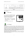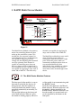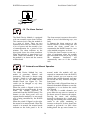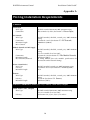
1
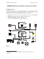
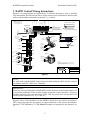
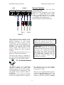
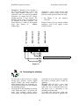
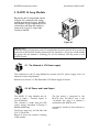
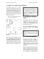
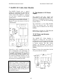
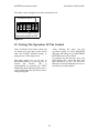
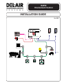
RAPID
Environment Control
INSTALLATION GUIDE
Ver 99C
RAPID
Environment Control
1
2
3
4
5
6
7
8
9
Room
Ambient
0
Creep
Installation Guide Ver99C
RAPID Environment Control
RAPID ENVIRONMENT CONTROL - INSTALLATION GUIDE
INTRODUCTION
The RAPID Control system is a distributed, networkable, 2 zone control that has been
designed to simplify and economize installation. Figure 1 is a block diagram of some of
the devices that can be connected to the RAPID Control. They include:
•
•
•
•
Two Module Networks for control of many types of devices in two independent
zones.
Two Sensor Inputs per zone plus an additional Ambient Sensor1 .
Alarm devices including a local siren or auto-dialer.
Central PC with RAPID-PC software package (optional).
RAPID
Environment Control
Model RAPID
Room
Ambient
Alarm / Warning Indicator
1
2
3
4
5
6
7
8
9
0
+/-
ESC
OK
120/240 V, 50/60 Hz
0.2/0.1 A, 24 VA
S
Y
S
T
E
M
Made in Canada
®
NRTL /C
LR 108984
S
Multi Device
Module
RAPID
Environment Control
Model MDM5
Alarm Indicator
Green = 0K
Red = Alarm
Variable Ouput 2 Indicator
Variable Ouput 1 Indicator
Manual Operation
Increase
1
Decrease
2
3
Output 3 Indicator
4
Output 4 Indicator
5
Output 5 Indicator
120/240 V, 50/60 Hz
S
Y
S
T
E
M
Made in Canada
®
NRTL /C
LR 108984
S
Creep
Figure 1
1
Only one ambient sensor may be required per facility if multiple controls are
networked.
1
RAPID Environment Control
Installation Guide Ver99C
WHEN
THIS CONTROL IS USED IN A LIFE SUPPORT HEATING AND
VENTILATION SYSTEM WHERE FAILURE COULD RESULT IN LOSS OR
INJURY, THE USER MUST INSTALL A FUNCTIONING ALARM SYSTEM AND
ADEQUATE BACK UP, OR ACCEPT THE RISK OF LOSS OR INJURY.
LIMITED WARRANTY
DEL-AIR SYSTEMS L TD. warrants to the original purchaser, that any device which
proves to be defective under normal use within two years from date of original purchase,
will be repaired or replaced without charge.
TERMS AND CONDITIONS
1. The warranty on this document does not apply:
a)
To any product subjected to misuse, negligence, abuse, defective or
improper wiring, improper installation, or any unit which has had the
serial number damaged or obliterated.
b)
To damage as a result of flood, fire, lightning, or any Acts of God.
2. Parts replaced or repaired under this warranty are warranted only through the
remainder of the original warranty.
3. This warranty does not cover cost of shipping defective or repaired or replaced
parts to or from original customer.
4. DEL-AIR Systems Ltd. reserves the right to make changes and improvements to its
product at any time with the express understanding that such changes and
improvements do not impose any obligation to install such changes and
improvements on products previously sold.
Except to the extent prohibited by applicable law, no other
warranty, whether expressed or implied, including the warranties of
merchantability and fitness for a particular purpose, shall apply to
this product. Any and all implied warranties are excluded. DEL-AIR
Systems Ltd. shall not be liable for consequential damages sustained
in connection with the said unit. DEL-AIR Systems Ltd. neither
assumes nor authorizes any representative or other person to
assume for it any obligation or liability other than such as it expressly
set for herein.
All complaints should be directed first to the authorized distributor
who sold the product. Only if satisfaction is not obtained or the
name of the distributor is not known should DEL-AIR Systems Ltd.
be contacted directly at 1 800 667 1722
2
RAPID Environment Control
Installation Guide Ver99C
Table of Contents
1
2
Pre-Installation Check__________________________________________________4
RAPID Control Wiring Instructions_______________________________________5
2.1 Power Input __________________________________________________________________________________________6
2.2 PC Network _________________________________________________________________________________________6
2.3 Alarm System ________________________________________________________________________________________7
2.4 Sensors______________________________________________________________________________________________8
2.5 The Module Network__________________________________________________________________________________9
2.6 Terminating the shielding _____________________________________________________________________________10
3
RAPID Multi Device Module ___________________________________________1 2
3.1
3.2
3.3
3.4
3.5
3.6
3.7
3.8
3.9
4
The Multi Device Modules Features ____________________________________________________________________12
The Network & 12V Power supply _____________________________________________________________________13
The AC Power Supply ________________________________________________________________________________14
The Variable Output Channels _________________________________________________________________________15
The Relay Output Channels____________________________________________________________________________15
The Alarm Contact __________________________________________________________________________________16
Automatic and Manual Operation ______________________________________________________________________16
Configuring the Multi Device Module ___________________________________________________________________17
Troubleshooting the Multi Device Module _______________________________________________________________17
RAPID 4 Amp Module_________________________________________________1 8
4.1 The Network & 12V Power supply _____________________________________________________________________18
4.2 AC Power and Load Output____________________________________________________________________________19
4.3 4 Amp Module Enclosure _____________________________________________________________________________20
5
RAPID 15 Amp Module________________________________________________2 1
5.1 The Network & 12V Power supply _____________________________________________________________________21
5.2 AC Power and Load Output____________________________________________________________________________21
5.3 15 Amp Module Enclosure ____________________________________________________________________________22
6
RAPID AC Curtain Control Module______________________________________2 3
6.1 The Network & 12V Power Supply _____________________________________________________________________23
6.2 AC Power and Load Output____________________________________________________________________________23
6.3 Installation Check ____________________________________________________________________________________24
7
RAPID DC Cable Inlet Module__________________________________________2 5
7.1 The Network & 12V Power Supply______________________________________________________________________25
7.2 AC Power and Actuator Connections ___________________________________________________________________25
7.3 Installation Setup and Test _____________________________________________________________________________26
8
Output Device Module_________________________________________________2 7
8.1 The Network & 12V Power supply ______________________________________________________________________27
8.2 The Load Output _____________________________________________________________________________________27
9
Module Addressing____________________________________________________2 8
10
Testing The Operation Of The Control __________________________________2 9
Appendix A ____________________________________________________________3 0
Appendix B ____________________________________________________________3 1
Appendix C ____________________________________________________________3 3
Appendix D ____________________________________________________________3 4
Appendix E ____________________________________________________________3 5
3
RAPID Environment Control
Installation Guide Ver99C
1 Pre-Installation Check
6
7
1
J7
TB1
2
3
4
5
Figure 2 - RAPID Control Circuit Board
Figure 2 - RAPID Control Circuit Board displays the features on the control circuit board
that are important to the installer. They include:
1. Main Power Fuse - Replacement: 3AG 2/10 Amp slow-blow, 250V.
2. Voltage Selector Switch. (See Section 2.1 Power Input)
3. PC-Network Fuses - Replacement: 2AG 1/8 Amp 250V
4. Module 12V Ground Fuses - Replacement: 2AG 1.5 Amp 250V
5. Battery - The RAPID Control uses a back-up battery to maintain time, date, and
logs when a power failure occurs. The RAPID Control is shipped with a piece of
paper under the battery clip so it will not discharge in shipping. Remove the paper
after the RAPID is installed to enable the battery.
6. DS1 - This LED will light when the RAPID Control is properly powered. If the LED
is off, no power is present.
7. RESET Switch - This switch (S2) is used to reset
Please refer to the troubleshooting guide for further information.
4
the
control.
RAPID Environment Control
Installation Guide Ver99C
2 RAPID Control Wiring Instructions
Ambient Sensor (-)
Zone 1 Sensor 1 (-)
Zone 1 Sensor 2 (-)
Zone 2 Sensor 1 (-)
Zone 2 Sensor 2 (-)
Partial Back View of 4 amp Module
22.
23.
24.
25.
26.
19, 20, 21. Sensor
Common Terminals (+)
Alarm 1 (-)
Alarm 1 (+)
Alarm 2 (-)
Alarm 2 (+)
15.
16.
17.
18.
NOTE:
Please read installation guide
for mounting instructions and
wire size recommendations.
11, 12, 13, 14.
No Connection
1. PC Network (-)
2. PC Network (+)
3. 12V Power Supply (-)
4. 12V Power Supply (+)
5. Module Network 1 (-)
6. Module Network 1 (+)
7. 12V Power Supply (-)
8. 12V Power Supply (+)
9. Module Network 2 (-)
10. Module Network 2 (+)
Figure 3 is a wiring diagram of a typical barn. To make the drawing as clear as possible
only the modules for one zone are shown. If the second room were identical there would
be the same modules connected to terminals 7, 8, 9 and 10.
USE WIRES SUITABLE FOR AT LEAST 90° C
ATTENTION: EMPLOYER DES FILS POUR AU MOINS 90°C
RAPID Control
J7
TB1
N L1
NOTE:
Select only one controller
to use ambient sensor and
connect pc-net terminals
on all controls as shown
in section 2.4 of Installation Guide
Cable
Cut lead of 2nd component ( C1 )
so that it no longer makes contact
( Only on 4A modules using a 25A relay )
Cable
Drain Wires connected to ground at 1 location only.On all
the rest of the connections drain wires are just tied together
Zone 1
SPDT Relay
Zone 1 Sensor 1
Cable from
previous module
L1
L2
To Heater
Ambient Sensor
Typical 4 amp
Module
4 amp Module
L2 L1
Zone 1 Sensor 2
Cable to
next module
(if electronic ignition heater)
ule
Mod es
id
Rap ress
Add
ter
Hea
To NW4K Fan
L1
L2
4 amp Module
To NW4K Fan
L1
L2
4 amp Module
To NW6K Fan
L1
L2
e1
Stag
e2
Stag
Sign
al
e3
Capacitor
Stag
p
+
Cree
12VD
C
r1
Time
-
r2
Time
L2 L1
r3
+
Time
r4
Time
r5
Time
A.
B.
C.
D.
E.
F.
G.
H.
Network ( - )
Network ( + )
12V ( - )
12V ( + )
L1 Switched (out)
L2 / N (out)
L2 / N (in)
L1 (in)
Load
PWR
Typical Fan
Connection
4 amp Module
SPDT Relay
L1
L2
To NW10K Fan
L2 L1
TB3
TB4
N
Motor
Actuator
A.
B.
C.
D.
Network ( - )
Network ( + )
12V ( - )
12V ( + )
E. L2 (White)
F. Switched (Blue)
G. L1 (Black)
Actuator
Potentiometer
TB1
C
TB2
CL
L2 L1
OL
To NW20K Fan
L1
O
L2 L1
SPDT Relay
Cable Inlet Module
SPDT Relay
To NW20K Fan
Typical 15 amp
Module
4 amp Module
NOTE:
25A relay must be used as shown if heaters are electronic ignition.
25A relay is not supplied by DEL-AIR.
Use Omron #G7L-2A-BUB-J-CB-AC120 or WW Grainger #2XC20
To 4 NW10K Fan L2
L1
L1
L2
DRAWING #
DRAWING TITLE:
Wiring Schematic
W-10-17-03
CUSTOMER:
DATE:
10/17/01
SCALE:
N.T.S.
Jason
DESIGN/DRAWN BY:
G.W./D.S.
SOLD BY:
DEL-AIR Systems Ltd
Figure 3
NOTE:
All wire used with the RAPID Control must be rated minimum 300V and be wired in
accordance with CEC/NEC class 1 methods.
IMPORTANT!
When any wiring is being done at the RAPID Control all power to the control must be off
to insure the protection of the installer and the protection of the electronics. All power
includes the power that runs the control (TB1), and any power that may be run to the
alarm contacts (terminals 15, 16, 17 and 18).
Figure 4 shows all the terminals on the RAPID Control that are used for installation.
TB1 is the power input for the control, all other connections to the control, described in
Sections 2.2 PC Network to 2.5 The Module Network, are connected to the terminals on
J7.
5
1 2 3
+
+
-
Sensor
(Common)
Alarm 2
Alarm 1
-
+ + + +
Zone2 Sensor2
-
Zone2 Sensor1
+
Zone1 Sensor2
-
Zone1 Sensor1
+
Network 2
12V supply
Network 1
-
Ambient Sensor
+
+5V
-
Digital Input 2
+
Digital Input 1
+5V
TB1
Installation Guide Ver99C
12V
PC Net
AC Input
RAPID Environment Control
-
-
-
-
-
1 2 3 4 5 6 7 8 9 10 11 12 13 14 15 16 17 18 19 20 21 22 23 24 25 26 J7
Figure 4
For all wire types, lengths and other information concerning the RAPID Control please
refer to Appendix A.
230
2.1 Power Input
Power is connected to the RAPID Control using
all the terminals of Terminal Block 1 (TB1). The
control’s power input is selectable to either 115
or 230 VAC. It will operate at 50/60 Hz.
Connect power as shown in Figure 5.
•
•
Before powering, make sure the power
selector switch is in the appropriate
position. See Figure 2 - RAPID Control
Circuit Board.
1
2
L1
L2
N
3
TB1
Figure 4 shows the position of TB1.
Figure 5
2.2 PC Network
The PC Network can be used with or without a computer connected to the network.
Connecting the PC-Net, with or without a computer, allows a single ambient sensor to be
used instead of every control in the facility needing an ambient sensor. The control with
the ambient sensor will broadcast the ambient temperature over the PC-Net to the other
controls. The second use for the PC-Net is connecting the controls to a PC running the
RAPIDPC software package. Using RAPIDPC you can view in real time how the control
is operating, make changes to settings, and log temperatures and events. As an
alternative to having a computer in the barn, RAPIDPC REMOTE can be installed so
that you dial into the network with a remote computer.
The RAPID Control uses an RS-485 twisted-pair network to connect all controls and an
optional computer together. The connection is made using a daisy-chain configuration.
The Daisy Chain is shown below:
6
RAPID Environment Control
Computer
Installation Guide Ver99C
RAPID Control 1
From Computer
RAPID Control 2
-
+
-
+
1
2
1
2
To Control
To Next Control...
Figure 6
IMPORTANT:
The network connection is polarity
sensitive. Ensure that all wiring is
consistent between all devices.
What Is A Daisy-Chain Configuration?
Like a chain, the network is linked so
that there are only two ends. This is a
requirement for the communications
network. It is not permissible to split the
connection at one control and go to
multiple controls, as this would create
more than two ends in the chain. As
well, the chain is not looped together; it
must be installed such that there are two
ends.
HINT:
The PC Network wires and the Alarm
System wires can be run in a single 2
pair twisted pair cable since both these
pair usually run to all the controls and
then back to a central office where the
computer and alarm are located.
IMPORTANT:
Network wires must be in separate
conduit from high voltage lines and must
be at least 16” from parallel running
high voltage lines. If Network wires
cross any high voltage wires they must
cross at 90°.
2.3 Alarm System
The RAPID Control has two normally open contacts (terminals 15, 16 and terminals 17,
18) which may be used to control a central auto-dialer or local siren. When the RAPID
Control is properly powered, the contacts on the relay are open (with no alarms). These
contacts will remain open until an alarm occurs. Alarms include: High Temp, Low Temp,
Sensor Failure and Power Failure.
7
RAPID Environment Control
Installation Guide Ver99C
Connecting to an auto-dialer:
Autodialer
From autodialer
Control 1
Control 2
- +
- +
15
15
16
To Control
16
To next control...
Figure 7
See Figure 4 for the terminal positions.
•
•
The auto-dialer should not be
connected until all controls have
been connected.
Refer to the installation guide that
was included with your autodialer
for more information.
-
+
17
18
Connecting to a local siren:
V
Either pair of alarm terminals may be
used to power any device that does not
exceed 1.0 Amp @120VAC or 2.0 Amps
@25VDC. The device must be powered
by an external supply.
( External Power Supply not included. )
Figure 8
2.4 Sensors
Each standalone control must have one ambient sensor and at least one room sensor
per zone. The ambient sensor must be installed on each control unless the PC-Net is
connected. If the PC-Net is connected, only one control needs to have an ambient sensor
installed. The control that has the ambient sensor installed and enabled will transmit the
ambient temperature to the rest of the controls over the PC-Net.
8
RAPID Environment Control
22
23
24
25
26
Sensor 1
Sensor 2
21
-
Sensor 2
20
Ambient
19
BLACK
-
-
Sensor 1
RED
+
+
+
Installation Guide Ver99C
Zone 1
Sensor Options
-
Sensor 1 must always read the Zone
(room) temperature.
Sensor 2 can be configured as the Creep
Sensor or a second Zone Sensor. When
used as a second Zone Sensor, its reading
is averaged with Sensor 1 to give the
average Zone (room) temperature.
See User Manual for more information.
Zone 2
Figure 9
There are three common terminals on the
sensor block (19 to 21). These are the
positive terminals of the sensor,
indicated by a red (or white) wire. The
positive wires may be tied together and
installed in any of the three positive
terminals. The negative wire on the
sensors (black wire) connects to the
terminal labeled for that particular
location.
e.g. The creep sensor for Zone 1 has its
black wire connect to terminal 24.
NOTE:
Sensor wires can be run in the same
conduit as the module network wires.
IMPORTANT:
Sensor wires must be in separate
conduit than high voltage lines and must
be at least 16” from parallel running
high voltage lines. When crossing high
voltage lines, sensor wires must cross at
90°. Temperature readings may be
affected by electrical noise if this
precaution is not taken
The drain wire, which is connected to
the cable shield, should be connected to
the ground wire at the RAPID Control.
RAPID
Environment Control
1
4
7
2
3
5
6
8
9
0
2.5 The Module Network
the electronic part of the module.
Therefore, the Daisy Chain will be made
using 2 pairs of wires.
The RAPID Control uses distributed
“SMART” modules to control both
Variable Speed and On/Off outputs.
The RAPID Control communicates with
the modules using a network similar to
the PC-Net.
In addition to the network, the RAPID
Control also supplies the DC voltage for
There are two module network outputs
on the control. Terminals 5 and 6 are
used for Module Network 1 and
terminals 9 and 10 are used for Module
9
RAPID Environment Control
Installation Guide Ver99C
Networks 1 and 2 must not be tied
together. A separate Daisy Chain must
be run for each network if both are used.
•
See Figure
locations.
4 for the terminal
Module Network 2
Figure 10 shows how to connect module
network 1 and its 12V supply at the
RAPID Control.
12V Power Supply
12V Power Supply
Module Network 1
Network 2. Related to the network is
the 12V power, terminals 3 and 4 are
used with Module Network 1 and
terminals 7 and 8 are used with Module
Network 2 to supply the 12V power.
Neither network is zone specific. The
RAPID Control sends all commands to
all modules over both networks. The
Zone selection is made on the module
itself (See Section 9
Module
Addressing).
-
+
-
+
-
+
-
+
3
4
5
6
7
8
9
10
1
2
... See Section 3.2, 4.1, 5.1, 6.1 7.1 and 8.1
3
4
Figure 10
RAPID
Environment Control
1
4
7
2
3
5
6
8
9
0
2.6 Terminating the shielding
caused by AC wires that may be around
the cable to extreme spikes caused by
lightning.
Shielded cable will have a bare wire
included with the other wires in the
cable. This wire is called the drain wire.
The drain wire is connected to the
shielding inside the cable.
To protect the wires from spikes the
drain wire must be tied to ground. The
All the wire used for the low voltage
wiring, (12V, network, sensors, digital
inputs, PCNET and alarm) should be
using shielded cable (see Appendix A).
This section describes how to terminate
the shielding properly.
The purpose of the shielding around the
wires inside the cable is to protect the
wires from induced voltage spikes.
These spikes can range from small noise
10
RAPID Environment Control
Installation Guide Ver99C
Connecting the drain wire for the
PCNET and alarm is somewhat
different. Since the drain wire is to be
connected to ground at one spot only,
DO NOT connect the drain to ground at
each control. Pick ONE location to
connect the drain to ground, this could
be at one control OR where the cable
goes to the alarm system OR where the
cable comes to the computer system.
Ideally the ground that any electronics
are connected to should be an isolated
ground, a ground that is used
specifically for the electronic equipment.
This is not necessary but can be decided
by the electrician doing the wiring as
well
as
the
electrical
code.
drain wire should be connected directly
to the ground wire, not using any of the
RAPID Control terminals to make the
connection. This should be done at one
point only, never have the drain wire
connected to ground at more than one
point per cable. For sensors that means
connecting the drain wire to ground at
the control. For the module network,
12V and digital inputs that means
connecting the drain wire to ground at
the control. For the entire length of cable
to be protected, the drain wire in the
cable coming into the module must be
connected to the drain wire in the cable
going out of the module.
11
RAPID Environment Control
Installation Guide Ver99C
3 RAPID Multi Device Module
Multi Device
Module
RAPID
Environment Control
Model MDM5
Alarm Indicator
Green = 0K
Red = Alarm
Variable Ouput 2 Indicator
Variable Ouput 1 Indicator
Manual Operation
3
Output 3 Indicator
1 2 4
Output 4 Indicator
5
Output 5 Indicator
Increase
Decrease
120/240 V, 50/60 Hz
S
Y
S
T
E
M
Made in Canada
®
NRTL /C
S
LR 108984
Figure 11
channels are capable of supplying 10
amps each at either 120 or 240VAC.
The Multi Device Module is the primary
means for controlling the devices that
make up the ventilation system. This
module has five separate outputs for
controlling devices. Two of the channels
are capable of supplying variable
voltage out, the remaining three channels
are relay operated. Each channel is
capable of controlling more than one
device as long as the maximum load is
not exceeded. The two variable channels
are capable of supplying 5 amps each at
either 120 or 240VAC. The three relay
Multi Device
Module
RAPID
Environment Control
Model MDM5
Alarm Indicator
Variable Ouput 2 Indicator
Green = 0K
Red = Alarm
Variable Ouput 1 Indicator
Increase
Decrease
Manual Operation
3
1 2 4
5
120/240 V, 50/60 Hz
S
Y
S
T
E
M
S
The Multi Device Module is most useful
when all of the power cables are
connected to each device from a single
point. When the power cables are
connected to multiple devices that are
not controlled identically then
individual 4 Amp modules are a better
choice for the control of the devices
since these can be mounted right at the
device.
3.1 The Multi Device Modules Features
Output 3 Indicator
Output 4 Indicator
Output 5 Indicator
Made in Canada
®
NRTL /C
LR 108984
The front panel of the module is set up to
show when each of the five devices are
being powered, when the module is in
alarm and whether the module is being
controlled automatically or manually (see
Figure 11).
The top right indicator on the front panel
is the alarm indicator. When it is green
the module is running properly, when it is
red the module is not communicating with
the RAPID Control.
Under the alarm indicator is the Manual
Mode indicator. When the indicator is off,
the module is being controlled by the
RAPID control. When the indicator is on
then the module is in manual mode and
can be controlled by the buttons on the
front panel.
12
RAPID Environment Control
Installation Guide Ver99C
Above buttons 1 and 2 and to the right of
buttons 3, 4 and 5 are channel output
indicators. These indicators show whether
the module is supplying power to the
devices on that channel or not. Since
channels 1 and 2 are variable, the indicator
brightens and dims according to the
amount of power being supplied by the
module for that channel. The indicators
Multi Device
Module
RAPID
Environment Control
3.2 The Network & 12V Power supply
Model MDM5
Alarm Indicator
Green = 0K
Red = Alarm
Variable Ouput 2 Indicator
Variable Ouput 1 Indicator
Increase
Decrease
Manual Operation
3
1 2 4
5
for channels 3, 4 and 5 are either on or off
depending on the state of that channel.
The Multi device module board inside has
two more indicators (see Figure 12). On
the top left area of the board is DS2. DS2
will flash when it sees communication on
the network wires. DS5 is located below
DS2. DS5 is on when the Multi Device
Module is being properly powered.
Output 3 Indicator
Output 4 Indicator
Output 5 Indicator
®
120/240 V, 50/60 Hz
Made in Canada
NRTL /C
S
Y
S
T
E
M
S
LR 108984
AUTO
MAN
CH1
Multi-Device Module
DEL-AIR SYSTEMS LTD.
CH2
CH3
CH4
CH5
F2
SW6
2AG
1/8A
DS2
F1
JP1
JP3
JP4
DS5
3AG
1/2A
250V
F3
JP2
CH1
NET 12V
AC Input
CH2
CH3
CH4
CH5
ALARM
115
TB1
TB3
TB4
TB5
TB6
TB7
TB8
TB2
- + - +
L1 L2 Gnd
Load Line
Load Line
Figure 12
IMPORTANT!
When any wiring is being done at the Multi Device Module all power must be off to
insure the protection of the installer and the protection of the electronics. All power
includes the power that runs the module (TB2), the power that is run to each of the
channels (including alarm) and the power to the RAPID Control.
On the bottom left of the Multi Device Module board is the network and 12V supply
terminals (TB1). The network and 12V wires from the RAPID Control are connected to
these terminals. Section 2.5 The Module Network shows the terminal locations of the
network and power supply on the RAPID Control. The connection at the module is
shown in Figure 13:
13
Installation Guide Ver99C
Module Network
Module Network
IMPORTANT:
Network and 12V terminals are
reversed on the modules compared
to the placement on the RAPID
control.
MODULE 2
12 V Power Supply
MODULE 1
12 V Power Supply
RAPID Environment Control
-
+
-
+
-
+
-
+
A
B
C
D
A
B
C
D
1
From Control
See Section 2.5
2
3
The
4
Module Network
Figure 13
Since it is self powered it is not
necessary to run the 12V wires to the
module although generally it is easier to
run the wires to it and then carry on to
the next modules that do need the 12V
wires.
In the case of surges on the
communication lines the module is
protected by a surge suppression circuit.
In the event of an extreme surge the
communication lines are also protected
with fuses.
NOTE:
Network wires must be in conduit
separate from high voltage lines and
must be at least 16” from parallel
running high voltage lines. If network
wires cross high voltage wires they must
cross at 90°.
The Multi module is the only module
that is self-powered and is able to run
without the 12V wires being attached.
Multi Device
Module
RAPID
Environment Control
Model MDM5
3.3 The AC Power Supply
Alarm Indicator
Variable Ouput 2 Indicator
Green = 0K
Red = Alarm
Variable Ouput 1 Indicator
Increase
Decrease
Manual Operation
3
1 2 4
5
Output 3 Indicator
Output 4 Indicator
Output 5 Indicator
®
120/240 V, 50/60 Hz
Made in Canada
NRTL /C
S
Y
S
T
E
M
S
LR 108984
Control’s AC input. Figure 14 shows the
connections.
Unlike the other RAPID modules, the
electronics on the Multi Device Module
is powered by 120/240VAC instead of
the 12V supply from the RAPID
Control. There is a separate terminal
block (TB2) for AC power to be
connected that runs the electronics on
the board. The power can be split off
from either of the variable channels or be
supplied from a separate breaker. There
must be a ground wire run to the
module. The AC input is to supply only
the power needed to run the electronics
on the board and it not used for any of
the output channels.
The AC power terminal block (TB2) is
located to the right of the Network/12V
terminal block The connections for the
AC are set up identically to the RAPID
1
2
L1
L2
N
3
TB2
Figure 14
Before applying power to the Multi
module ensure that the voltage selector
switch is in the proper position for the
power that is connected to the AC
input.
14
RAPID Environment Control
Multi Device
Module
RAPID
Environment Control
Model MDM5
Alarm Indicator
3.4 The Variable Output Channels
Green = 0K
Red = Alarm
Variable Ouput 2 Indicator
Variable Ouput 1 Indicator
Increase
Decrease
Manual Operation
3
1 2 4
5
Installation Guide Ver99C
Output 3 Indicator
Output 4 Indicator
Output 5 Indicator
®
Made in Canada
120/240 V, 50/60 Hz
NRTL /C
S
Y
S
T
E
M
S
LR 108984
The variable channels are labeled as
CH1 and CH2. These channels can be
configured to run any of the devices
listed in Table 2 of Section 9 Module
Addressing.
NOTE:
Each module must have the AC
connected to terminals 3 and 4. For
120V, the Line is connected to terminal
4 and the Neutral to terminal 3. For
240V, either leg can be connected to
terminals 4 and 3, as long as both legs
are connected.
The Power input may be 120/208/240
VAC @ 50/60 Hz. Figure 15 shows the
internal switching of the module. Each
channel is made up of a four terminal
block. The power enters on terminal 4.
The “switched” line to the motor is
terminal 1. The direct (common) line is
connected to terminals 2 and 3. The
direct line must be connected to the
module so that it can make the
necessary measurement for speed
control and On/Off commands.
NOTE:
Stranded wire is recommended since it
is much more flexible than solid wire.
Solid wire may damage the terminal
block.
IMPORTANT:
Do NOT use the Multi modules variable
channels to switch relays. The leakage
current of the module may keep the coil
energized even when the module turns
off.
A module is wired to a load or device as
shown in Figure 15.
(Internal to Module)
1
Load
2
3
4
NOTE:
You can not measure the voltage of the
output of the variable channels if there
is no load attached. When there is no
load, the output will show whatever the
input voltage is, so readings will not
accurately show the state of the module.
AC Power Input
Figure 15
Multi Device
Module
RAPID
Environment Control
Model MDM5
3.5 The Relay Output Channels
Alarm Indicator
Variable Ouput 2 Indicator
Green = 0K
Red = Alarm
Variable Ouput 1 Indicator
Increase
Decrease
Manual Operation
3
1 2 4
Output 4 Indicator
5
Output 5 Indicator
120/240 V, 50/60 Hz
S
Y
S
T
E
M
S
Output 3 Indicator
Made in Canada
®
NRTL /C
LR 108984
terminal block. The power enters on
terminal 2. The “switched” line is
terminal 1. This channel is simply a
relay that switches power just like a
light switch. The Line 2/Netural wire
does not get connected to the module.
A module is wired to a load or device as
shown in Figure 16.
The relay channels are labeled as CH3,
CH4 and CH5. These channels can be
configured to run any of the devices
listed in Table 2 of Section 9 Module
Addressing.
The Power input may be 120/208/240
VAC @ 50/60 Hz. Figure 16 shows the
internal switching of the module. Each
channel is made up of a two screw
15
RAPID Environment Control
Installation Guide Ver99C
(Internal to Module)
1
2
AC Power
Input
Load
Figure 16
Multi Device
Module
RAPID
Environment Control
Model MDM5
Alarm Indicator
Green = 0K
Red = Alarm
Variable Ouput 2 Indicator
Variable Ouput 1 Indicator
Increase
Decrease
Manual Operation
3
1 2 4
5
3.6 The Alarm Contact
Output 3 Indicator
Output 4 Indicator
Output 5 Indicator
®
Made in Canada
120/240 V, 50/60 Hz
NRTL /C
S
Y
S
T
E
M
S
LR 108984
The alarm contact is meant to be used in
either of two of the following ways, not
both.
1) Connect the alarm contact to the
RAPID control’s alarm. Doing this will
activate the alarm system that is
connected to the RAPID control as soon
as the module recognizes an alarm.
2) Wire the alarm contact to turn on a
piece of equipment when the module
goes into alarm. It may be set up so that
the
minimum
ventilation
will
automatically turn on if the module
fails.
The Multi Device Module is equipped
with one normally open alarm contact.
This contact closes when the module is
in a state of alarm. There are two
conditions that cause an alarm, the first
is loss of power and the second is loss
of communication for a period of five
minutes. The alarm indicator on the
front panel shows the alarm condition.
When the indicator is green there is no
alarm. When the indicator is red then
the module is in alarm and the contact
will be closed.
Multi Device
Module
RAPID
Environment Control
Model MDM5
3.7 Automatic and Manual Operation
Alarm Indicator
Variable Ouput 2 Indicator
Green = 0K
Red = Alarm
Variable Ouput 1 Indicator
Increase
Decrease
Manual Operation
3
1 2 4
5
Output 3 Indicator
Output 4 Indicator
Output 5 Indicator
®
120/240 V, 50/60 Hz
Made in Canada
NRTL /C
S
Y
S
T
E
M
S
LR 108984
manual mode the module will not
respond to commands from the RAPID
control, instead you can increase and
decrease the variable channels and turn
on and off the relay channels using the
front panel.
When the switch is flipped from Auto to
Manual, the module continues to run the
equipment as it was before the switch
was flipped.
To vary the 2 variable channels you
press either the up arrow to increase or
the down arrow to decrease the output.
Pressing the arrow and releasing
increases or decreases by a single step.
Pressing and holding the arrow button
results in the speed continuing to
increase or decrease. It takes about four
seconds to go from 0% to 100% when
holding down the up arrow button. As
The Multi Device Module has two
modes of operation; Manual and
Automatic. The mode is chosen using
Switch 6. Switch 6 is the toggle switch
on the top left of the Multi Device
Module board (see Figure 12). This
switch can be changed at any time,
powered or not.
When the switch is flipped to the left,
the control is in automatic mode. In auto
mode, the module responds to
commands from the RAPID control. The
buttons on the front panel will not
operate then the module is in auto mode
and is being controlled by the RAPID
control.
When the switch if flipped to the right,
the control is in manual mode. When the
control is in manual, the manual mode
indicator on the front panel is lit. In
16
RAPID Environment Control
Installation Guide Ver99C
you increase and decrease the variable
channels, the indicator for that channel
will brighten and dim accordingly.
To turn the 3 relay channels off and on
press the number button for that
Multi Device
Module
RAPID
Environment Control
Model MDM5
Alarm Indicator
3.8 Configuring the Multi Device Module
Green = 0K
Red = Alarm
Variable Ouput 2 Indicator
Variable Ouput 1 Indicator
Increase
Decrease
Manual Operation
3
Output 3 Indicator
1 2 4
Output 4 Indicator
5
channel. When the channel is on the
indicator for the channel will be lit,
when the channel is off the indicator will
go off as well.
Output 5 Indicator
®
Made in Canada
120/240 V, 50/60 Hz
NRTL /C
S
Y
S
T
E
M
S
LR 108984
Each of the channels is configured using
the blocks of switches in the top right
side of the circuit board. Each of the
switch blocks is labeled for which
channel it configures. Channel 1 is on the
Multi Device
Module
RAPID
Environment Control
Model MDM5
Alarm Indicator
Variable Ouput 2 Indicator
Increase
Decrease
3.9 Troubleshooting the Multi Device Module
Green = 0K
Red = Alarm
Variable Ouput 1 Indicator
Manual Operation
3
1 2 4
5
far left and channel 5 is on the far right.
These switches can be changed at any
time, when the board is powered or not.
See Section 9 Module Addressing for
the addressing codes.
Output 3 Indicator
Output 4 Indicator
Output 5 Indicator
®
120/240 V, 50/60 Hz
Made in Canada
NRTL /C
S
Y
S
T
E
M
S
LR 108984
likely reversed. If the indicator does not
light up at all then check fuses F1 and
F2.
The module can also be tested without
having to be connected to the RAPID
Control or with the control off. With
power being supplied to the module,
switch SW6 to the right (Manual Mode)
and use the front panel to turn on and
off the channels.
If the display does not respond, make
sure the ribbon cable from the front
panel is plugged into JP3 properly.
When the Multi Device Module is
powered, DS5 on the circuit board
should light up. If it does not light up
check the breaker, the voltage selector
switch and the main fuse (F3). If all of
these are OK then measure the voltage
at the AC input to make sure it is OK.
If the network wires are connected and
the RAPID Control running, DS2 on the
circuit board should be flashing.
Generally the light will be off for two
seconds and then will flash very quickly
for 3 seconds. If the light is doing the
reverse then the network wires are most
17
RAPID Environment Control
Installation Guide Ver99C
4 RAPID 4 Amp Module
Having modules designed this
allows:
•
•
•
Figure 17
The 4 Amp Module consists of three
main parts:
1. RAPID Module Network & Power
Supply Input Terminals.
2. Module Addressing Switches. (DIP
Switches)
3. AC Power Input and Load Control
Output Terminals.
way
Modules to be located near the load
that it is operating. AC power does
not have to be brought back to the
control for each load that is
controlled.
Control of multiple devices on any
stage.
Greatly
reduced
electrical
management of the facility. The
module itself reads the phase
information from the AC input to
provide variable speed control for
the load. The module’s power input
does not have to be on the same
phase as the control itself. Two or
more modules addressed to the
same stage do not have to be on the
same phase of power.
IMPORTANT!
When any wiring is being done at the 4Amp Module all power must be off to insure the
protection of the installer and the protection of the electronics. All power would include
the power that the module is switching (L1 and L2/Neutral) and the power to the
RAPID Control.
4.1 The Network & 12V Power supply
The network and 12V terminal block is the terminal block on the left side of the module
as shown in Figure 17. Section 2.5 The Module Network shows the terminal locations of
the network and power supply on the RAPID Control. The connection at the module is
shown in Figure 18:
18
RAPID Environment Control
Installation Guide Ver99C
12 V Power Supply
Module Network
Module Network
IMPORTANT:
Network and 12V terminals are
reversed on the modules compared
to the placement on the RAPID
control.
12 V Power Supply
MODULE 1 MODULE 2
-
+
-
+
-
+
-
+
A
B
C
D
A
B
C
D
1
From Control
See Section 2.5 The
2
Module Network
4
3
Figure 18
4.2 AC Power and Load Output
The RAPID 4 Amp Module may be used
as either a Variable Speed or On/Off
Module.
This selection is made using the DIP
switch settings described in Section 9
Module Addressing.
NOTE:
Each module must have the AC
connected to terminals G and H. For
120V, the Line is connected to terminal
H and the Neutral to terminal G. For
240V, either leg can be connected to
terminals G and H, as long as both legs
are connected.
The Power input may be 120/208/240
VAC @ 50/60 Hz. Figure 19 shows the
internal switching of the module. The
power enters on terminal H. The
“switched” line is terminal E. The direct
(common) line is connected to terminals
F and G. The direct line must be
connected to the module so that it can
make the necessary measurement for
speed control and On/Off commands.
IMPORTANT:
When using the 4ADM to operate a
relay, you must cut the leg of the
capacitor on the 4ADM as shown in
Figure 20. Use relays with 120VAC
coils such as the Omron G4L series
relay.
A module is wired to a load or device as
shown in Figure 19.
Partial Back View of 4 amp Module
(Internal to Module)
USE WIRES SUITABLE FOR AT LEAST 90° C
ATTENTION: EMPLOYER DES FILS POUR AU MOINS 90°C
E
Load
F
G
H
Cut lead of 2nd component from left ( C1 )
so that it no longer makes contact.
( Only on 4A modules controling a relay )
AC Power Input
Figure 19
Figure 20
19
RAPID Environment Control
Installation Guide Ver99C
NOTE:
You can not measure the voltage of the
output of the 4 Amp Module if there is
no load attached. When there is no
load, the output will show whatever the
input voltage is, so readings will not
accurately show the state of the module.
NOTE:
Network wires must be in separate
conduit than high voltage lines and must
be at least 16” from parallel running
high voltage lines. If network wires cross
high voltage wires they must cross at
90°.
4.3 4 Amp Module Enclosure
The RAPID 4 Amp Module does not come with its own enclosure. It has been designed
to fit in a standard single gang F Series Scepter brand box or equivalent.
The enclosure chosen for the 4 Amp Module must be a CSA and UL approved
non-metallic box with sizing of at least 4 1/4” X 3 1/2” X 2” with NEMA 4 rating.
IMPORTANT:
Ensure that the enclosure is properly
sealed once the module is coded and
wired.
Improper sealing of the enclosure may
lead to an electrical failure at the
module as a result of moisture damage.
IMPORTANT:
The 4 Amp module enclosure should be
mounted so the module sits vertically,
as in Figure 21, and not horizontally.
Do not mount the module on the ceiling.
When mounted vertically, the module
will be less likely to be affected by
moisture and contaminants present in
the barn.
Figure 21
The module slides in between the lid
mounting screws on the side of the
enclosure.
20
RAPID Environment Control
Installation Guide Ver99C
5 RAPID 15 Amp Module
Electrically, the 15 Amp module (shown
in Figure 22) is identical to the 4 Amp
module described in Section 4 RAPID 4
Amp Module. Larger components and an
external heat sink allow this module to
power loads at up to 15 Amps either
variably or On/Off.
Figure 22
IMPORTANT!
When any wiring is being done at the 15 Amp Module all power must be off to insure the
protection of the installer and the protection of the electronics. All power would include
the power that the module is switching (L1 and L2/Neutral) and the power to the
RAPID Control.
5.1 The Network & 12V Power supply
The connections at the 15 Amp Module for network and 12V power supply wires are
identical to the 4 Amp Module.
Refer back to Section 4.1 The Network & 12V Power supply for details.
5.2 AC Power and Load Output
The line power is connected to the
BLACK wire. The BLUE wire is the
“switched” line. Line 2 or Neutral is
connected to the WHITE wire.
The RAPID 15 Amp Module may be
used as either a Variable Speed or
On/Off Module.
This selection is made using the DIP
switch settings described in Section 9
Module Addressing.
A module is wired to a load or device as
follows:
The Power input may be 120/208/240
VAC @ 50/60 Hz.
Figure 23 shows the internal switching
of the module.
21
RAPID Environment Control
Installation Guide Ver99C
(Internal to Module)
Blue
White
NOTE:
Network wires must be in separate
conduit than high voltage lines and must
be at least 16” from parallel running
high voltage lines. If network wires cross
high voltage wires they must cross at
90°.
Black
Line 1
Line 2
Load
NOTE:
You can not measure the voltage of the
output of the 15 Amp Module if there is
no load attached. When there is no
load, the output will show whatever the
input voltage is, so readings will not
accurately show the state of the module.
AC Power Input
Figure 23
NOTE:
Each module must have the AC
connected to the Black and White wires.
For 120V, the Line is connected to Black
and the Neutral to White. For 240V,
either leg can be connected to Black and
White, as long as both legs are
connected.
5.3 15 Amp Module Enclosure
The RAPID 15 Amp Module comes with
its own enclosure. It is shipped in a
modified Scepter brand FDC15 or
FDC20. The module can be replaced
without removing the entire enclosure
but the module will not fit into a
standard FDC box.
The module slides in between the lid
mounting screws on the side of the
enclosure.
IMPORTANT:
Ensure that the enclosure is properly
sealed once the module is coded and
installed.
Improper sealing of the enclosure may
lead to an electrical failure to the
module as a result of moisture damage.
IMPORTANT:
Install the enclosure as shown in Figure
24. If it is installed in another
orientation the heat sink may not have
enough airflow and could overheat
Figure 24
22
RAPID Environment Control
Installation Guide Ver99C
6 RAPID AC Curtain Control Module
The RAPID Control uses a special
module for controlling the curtains used
in the Natural Ventilation system. The
Curtain Module is enclosed in a box that
is similar to the RAPID Control itself.
When the cover is opened, the board sits
in the top left corner of the enclosure.
Figure 25 shows the layout of the AC
Curtain circuit board.
•
IMPORTANT!
When any wiring is being done at the
curtain module all power must be off to
insure the protection of the installer and
the protection of the electronics. All
power would include the power that the
module
is
switching
(L1
and
L2/Neutral) and the power to the
RAPID Control.
TB2 is not used when the module is
set for curtain applications.
6.1 The Network & 12V Power
Supply
The network and 12V supply are
connected to TB1 of the Curtain
Module. The connections are in the same
order as the 4 Amp module. Refer back
to Section 4.1 The Network & 12V
Power supply for details.
DS2
DS1
CURTAIN MODULE
DS4
DS3
ON
DS5
DIP
Switches
Open
Section 2.5 The Module Network shows
the terminal locations of the network
and power supply on the RAPID
Control.
Close
TB2
TB1
Note:
The connections on the AC Curtain
Module for network and 12V power
supply wires are identical to the 4 Amp
Module.
TB3
Figure 25
6.2 AC Power and Load Output
Since this is still a module, it has the
basic configuration and advantages of
the 4 Amp Module described in Section
4 RAPID 4 Amp Module. In addition to
that, having curtain modules will allow
control of multiple curtains on any one
stage if a facility is large enough to need
multiple actuators for a stage of curtain.
The RAPID AC Curtain Module is
designed to switch the AC input to
operate a motor (actuator) in forward or
reverse motion. The module can be set to
operate Curtain 1, 2, 3 or 4. This
selection is made using the DIP switch
settings described in Section 9 Module
Addressing.
Figure 26 shows the internal switching
part of the module. Using TB3, line 1
enters the module on terminal 1 and the
neutral is wired directly to the motor.
The “switched” lines are terminals 2
and 3. Terminal 2 is activated for the
23
RAPID Environment Control
Installation Guide Ver99C
OPEN command and terminal 3 is
activated for the CLOSE command.
IMPORTANT:
Network wires must be in separate
conduit than high voltage lines and must
be at least 16” from parallel running
high voltage lines. If network wires cross
high voltage wires they must cross at
90°.
(Internal to Module)
1
2
3
TB3
Open
6.3 Installation Check
When the module has the 12VDC power
supplied as well as the AC power, the
control can be manually operated by
pressing the buttons labeled “O” (open),
and “C” (close). When “O” is pressed
DS2 should light and the curtain open.
When “C” is pressed DS1 should light
and the curtain should close. If the
actuator runs backwards (closes when
“O” is pressed) then wires on terminals
2 and 3 have to be reversed to correct
the problem.
Close
Line 1
Neutral
AC Power Input
Load
Figure 26
NOTE:
Pressing the “O” or “C” buttons will
override any signals sent by the control
at the time.
24
RAPID Environment Control
Installation Guide Ver99C
7 RAPID DC Cable Inlet Module
The RAPID Control uses a special
module for controlling the inlets used in
mechanical ventilation systems. The DC
Cable Control Inlet Module is enclosed
in a box that is similar to the RAPID
Control itself.
When the cover is opened, the board sits
in the top left corner of the enclosure.
Figure 27 shows the layout of the DC
Cable Module.
7.1 The Network & 12V Power
Supply
The network and 12V supply are
connected to the module using TB1.
Section 2.5 The Module Network shows
the locations of TB1 and the remaining
terminal blocks.
The connections at the Cable Module
(TB1) for network and 12V power
supply wires are identical to the 4 Amp
Module.
Fuse
DS2
DS1
Refer back to Section 4.1 The Network
& 12V Power supply for details
DS4
DS3
ON
DS5
7.2 AC Power and Actuator
Connections
DIP
Switches
Open
Close
OL
CL
TB2
TB1
TB4
The RAPID DC Cable Module is
designed to receive the AC input, it
converts this to a DC output that is able
to operate a motor (actuator) in forward
or reverse motion. The DIP switch
settings are described in Section 9
Module Addressing for the Inlet Control
Module.
TB3
Figure 27
Since this is still a module, it has the
basic configuration and advantages of
the 4 Amp Module described in Section
4 RAPID 4 Amp Module. In addition to
those advantages, having modules allow
for control of multiple actuators on any
zone if a facility is large enough to need
more than one actuator per zone.
Figure 28 shows the connections for the
AC power and the Actuator.
O
C
OL
CL
TB2
IMPORTANT!
When any wiring is being done at the
cable module all power must be off to
insure the protection of the installer and
the protection of the electronics. All
power would include the power that
runs the module (TB3) and the power to
the RAPID Control.
1 2 3
TB1
1 2 3 4
TB4
1 2 3 4
DC
Actuator
Potentiometer
Actuator
Figure 28
25
TB3
1
2
AC
In
RAPID Environment Control
Installation Guide Ver99C
the “OL” (Open Limit) button. When
the “OL” button is pressed DS4 lights
to indicate that the setting was saved.
The Closed Limit is set the same way,
by pressing the “C” button until the
inlets are closed and then pressing the
“CL” (Closed Limit) button. When the
“CL” button is pressed DS3 lights to
indicate that the setting was saved.
Connection Description:
•
•
•
Line 1 and Neutral enter the module
on terminals 1 and 2 of terminal
block TB3.
The DC output to the actuator is
from terminals 1 and 2 of terminal
block TB4.
The module uses a potentiometer
connected to the actuator for
position sensing. Terminal 1 of TB2
supplies the 5VDC and terminal 3
provides the ground for the pot.
Terminal 2 is the wiper of the pot; it
is this terminal that senses the
position of the actuator.
•
DS5 is an indicator that the network
wires are operational. The indicator
is off when no signal is present and
flashes when signals are present.
NOTE:
The control should be in Monitor
program while doing any manual
movement of the actuator from the
module itself.
7.3 Installation Setup and Test
When all connections to the module are
complete, the 12VDC power and AC
power may be applied. When it has
been powered, pressing the button
labeled “O” (open) should light DS2
and open the inlets; pressing the “C”
button should light DS1 and close the
inlets. If the inlets respond backwards
the wires on terminals 1 and 2 of TB4
can be reversed.
IMPORTANT:
When pressing the OPEN and CLOSE
buttons on the module, the only limit of
movement is any limit on the actuator
itself. Remember that while pressing
these buttons it is up to the user to judge
how long to continue movement, damage
to the inlet system may occur if
movement continues after the inlets have
reached their limits.
When the module has been tested to run
properly, it then needs to be set up. The
module needs to know the Open Limit
and Closed Limit. To set the Open Limit
press the “O” button until the inlets are
fully opened, when they are open press
26
RAPID Environment Control
Installation Guide Ver99C
8 Output Device Module
Some equipment is controlled by receiving a signal from a controller. 0-10VDC and 420mA are two common signals which equipment responds to. The Output Device Module
is designed to supply this type of signal.
The Output Device Module is able to be set to any of the addresses that the 4 Amp device
module can be set to (see Table 2). Instead of supplying an AC voltage output which
directly drives loads the Output Device Module supplies a DC voltage proportionally to the
range that it is set to supply.
8.1 The Network & 12V Power supply
The connections at the Output Device Module for network and 12V power supply wires
are identical to the 4 Amp Module.
Refer back to Section 4.1 The Network & 12V Power supply for details.
8.2 The Load Output
The module is able to supply only a small amount of current since it is not meant to power
the load. There are three different voltage ranges that the module can supply; 0-10V, 2-10V
and 3-7V. When a 4-20mA signal is required, use the 2-10V setting and a 500Ω resistor.
To select the voltage range set the S1, DIP switches as show in Table 1
Table 1
Output
0-10V
2-10V
3-7V
Switch 1
OFF
OFF
ON
Switch 2
OFF
ON
OFF
27
RAPID Environment Control
Installation Guide Ver99C
9 Module Addressing
Each module must be addressed to the device that it is controlling. This is necessary
because the RAPID Control sends all commands to all of the modules over the twisted
pair of wires.
The codes that the Multi Device Module, 4 Amp Module, 15 Amp Module and Output
Module can be set to are shown in Table 2.
Table 2
Controlled
Device
Stage 1 Zone Heater
Stage 2 Zone Heater
Creep Heater
Stage 0
Stage 1 Fan
Stage 2 Fan
Stage 3 Fan
Timer 1
Timer 2
Timer 3
Spray/Drip Cool
Stage 1 Tunnel Fan
Stage 2 Tunnel Fan
Stir Fan
Switch 1
Switch 2
Switch 3
Switch 4
Switch 5
OFF
ON
OFF
OFF
ON
OFF
ON
ON
OFF
ON
OFF
ON
ON
OFF
OFF
ON
OFF
ON
OFF
ON
ON
OFF
ON
ON
ON
OFF
ON
OFF
OFF
ON
ON
ON
OFF
OFF
OFF
ON
ON
ON
OFF
OFF
OFF
OFF
OFF
ON
OFF
ON
OFF
OFF
OFF
OFF
OFF
OFF
OFF
OFF
OFF
OFF
OFF
ON
OFF
ON
OFF
OFF
OFF
OFF
OFF
OFF
ON
ON
ON
ON
The codes that the Cable and Curtain Modules can be set to are shown in Table 3.
Table 3
Cable Control
Curtain 1
Curtain 2
Curtain 3
Curtain 4
OFF
OFF
OFF
OFF
OFF
OFF
OFF
OFF
OFF
OFF
OFF
OFF
ON
OFF
ON
OFF
ON
ON
OFF
OFF
OFF
OFF
OFF
ON
ON
Every module must be told what zone it is in. Table 4 shows how to address the zone
switch.
Table 4
Zone
Zone 1
Zone 2
Switch 6
OFF
ON
It is possible to set more than one module on the same code. If, for example, three Stage
1 fans are required in a zone, set all three modules to the same code. The RAPID Control
will communicate to and control all three modules simultaneously.
28
RAPID Environment Control
Installation Guide Ver99C
The codes can be changed at any time, powered or not.
The switch up is ON
ON
1
2
3
4
5
6
The switch down is OFF
Figure 29
10 Testing The Operation Of The Control
After selecting the zone, use the
up/down arrows to select MONITOR
and press OK. When it says PROGRAM
RUNNING press OK to finish.
To actually test the devices, press the
TEST button (#7), select the zone and
then the device to test. See the User
Manual for more information on how to
run the tests on the modules.
After all devices have been wired and
are ready to be run, they can be tested
from the RAPID without having to
program any of the setup into it.
First the control has to be put in
MONITOR mode so it does not try to
control
the
devices.
This
is
accomplished by pressing the VENT
button (#4), then selecting which zone is
to be tested using the up/down arrows
and pressing OK.
29
RAPID Environment Control
Installation Guide Ver99C
Appendix A
Wiring Installation Requirements
Control
Power Input
Wire type
Connections
PC Network
Wire Type
Connections
Maximum Length
Max. Controls
Module Network and 12V Supply
Wire Type
Connections
Maximum Length
Max. Modules/Network
Alarm (Auto-Dialer)
Wire Type
Polarity
Maximum Length
16 AWG stranded (minimum) 300V minimum rating
TB1 terminals 1,2 and 3 (See Section 2.1 Power Input)
20 AWG stranded, shielded, twisted pair, 300V minimum
rating
J7 terminals 1 and 2 (See Section 2.2 PC Network)
1200 Meters (3900 ft.)
31
20 AWG stranded, shielded, twisted pair, 300V minimum
rating
Use wire suitable for at least 90°C
J7 terminals 3-10 (See Section 2.5 The Module Network)
107 Meters (350 ft.)
32 4Amp Modules (See each module’s specifications for
the network under Network Rating)
20 AWG stranded, twisted pair, 300V minimum rating
J7 terminals 15 to 18 (See Section 2.3 Alarm System)
N/A
Sensor
Wire Type
Polarity
Maximum Length
20 AWG stranded, shielded, twisted pair, 300V minimum
rating
J7 19 to 26 (See Section 2.4 Sensors)
107 Meters (350 ft.)
Device Modules (Multi, 4A, 15A, Curtain, Cable Inlet, Output)
Load, Power (VAC Output)
Wire Type
Polarity
16 AWG stranded (minimum), 300V minimum rating
Use wire suitable for at least 90°C
See Sections 3.4, 3.5, 4.2, 5.2, 6.2, 7.2 and 8.2
30
RAPID Environment Control
Installation Guide Ver99C
Appendix B
RAPID Specification Sheet
Control Description
Power Input
Environment
Module Power Output
Digital Inputs (2)
Control Network
Alarm Outputs (2)
Temperature Sensor Inputs (5)
Main Power Fuse
PCNET Fuses
12V Ground Fuses
120 /240 VAC (108-127/212-254),
0.2/0.1A 50/60 Hz
0-50°C (32-122°F) non-condensing
12 VDC unregulated (9.12 VDC - 14.8 VDC),
1.8 Amp
5 VDC
RS-485
Relay Contact, Normally Open
1.0 Amp @ 120VAC, 2.0 Amp @ 25VDC.
AD590, resolution: ± 0.1°C
3AG 2/10 Amp slow blow 250V
2AG 1/8 Amp 250V
2AG 1.5 Amp 250V
Multi Device Module Description
Type
2 - Variable voltage dimmer channels
3 - Relay operated channels
AC Power Input
120 /240 VAC (108-127/212-254),
0.2/0.1A 50/60 Hz
Environment
Variable Channel Output Rating
Relay Channel Output Rating
Module Network
Main Power Fuse
Network Rating
Network Fuses
0-50°C (32-122°F) non-condensing
5 Amps per channel
10 Amps per channel
RS-485
3AG 1.0 Amp 250V
1-4Amp module
2AG 1/8 Amp 250V
4 Amp Module Description
Type
AC Power Input
DC Power Input
Environment
Output Rating
Network Rating
Module Network
Variable voltage dimmer
120/208/240 VAC (104-127/187-220/208-254)
50/60Hz
10-16VDC
0-50°C (32-122°F) non-condensing
4 Amp
1-4Amp Module
RS-485
15Amp Module Description
Type
AC Power Input
DC Power Input
Environment
Output Rating
Network Rating
Module Network
Variable voltage dimmer
120/208/240 VAC (104-127/187-220/208-254)
50/60Hz
10-16VDC
0-50°C (32-122°F) non-condensing
15A
1-4Amp Module
RS-485
31
RAPID Environment Control
Installation Guide Ver99C
Cable Control Module Description
Type
AC Power Input
DC Power Input
Environment
Rating (Output)
Module Network
Network Rating
Fuse
Relay operated
120/208/240 VAC (104-127/187-220/208-254)
50/60Hz
10-16VDC
0-50°C (32-122°F) non-condensing
30VDC, 1.6 A (2.8A peak) @ 60 Hz
30VDC, 1.5A (2.8A peak) @ 50 Hz
RS-485
4-4Amp Modules
3AG 4.0 Amp 250V
Curtain Control Module Description
Type
AC Power Input
DC Power Input
Environment
Network Rating
Rating (Output)
Module Network
Relay operated
120/208/240 VAC 50/60Hz
10-16VDC
0-50°C (32-122°F) non-condensing
4-4Amp Modules
10A DC
RS-485
Output Device Module Description
Type
DC Power Input
Environment
Rating (Output)
Network Rating
Module Network
DC output
10-16VDC
0-50°C (32-122°F) non-condensing
20mA DC
2-4Amp Modules
RS-485
32
RAPID Environment Control
Installation Guide Ver99C
Appendix C
TROUBLESHOOTING GUIDE
Symptom
Check ...
No power to control.
DS1 not lit.
1.
Breaker
2.
Fuse
3.
Voltage Selector Switch in correct position.
1.
Remove paper tab under battery.
2.
Check battery on control.
3.
Verify J6 has jumper on pins 2 and 3
1.
Check that sensors are enabled properly or are disabled if no
Calendar/clock incorrect
after power loss to
control.
Displays incorrect,
erratic temperature.
sensor is connected.
2.
Check sensor wiring at the control terminals. Make sure t h e
polarity is correct and wires are in proper terminals.
3.
Make sure the control and cable shielding are grounded.
4.
Check calibration. Re-calibrate if necessary.
5. Replace sensor.
Alarm doesn’t activate.
1.
Check the alarm band. Re-adjust if necessary.
2.
Run Alarm Test. Listen for clicking action on the alarm relay.
3.
Inspect wiring from control terminals to the alarm system.
4. Test alarm device without using the RAPID Control.
Module does not respond,
device or load does not
respond to RAPID
Control.
1.
Put the control in TEST and test the device in question.
2.
Check module address
3.
Check AC power input to the module, using a test light/meter.
4.
Check polarity of signal and power supply wires. †
5.
Check the load; by-pass the module and power the load
directly.
6.
If all tests above pass, replace the module.
† See SIGNAL TEST, Appendix D.
33
RAPID Environment Control
Installation Guide Ver99C
Appendix D
Paired-Wire Test Instructions
Important:
The following tests should be performed by a certified electrician. Consult
your dealer for further information.
These tests are included to provide assistance for the electrician. They are helpful in
confirming that all wiring installation is correct.
This test is performed to ensure that
signal is transmitted from the control to
the modules. If the module is not
responding to commands from the
control, it may be possible that the
wiring is faulty. To test the signals, a
digital or analog multimeter is required:
Testing the Module Network:
1. Use the same setting on the meter as
for the power supply test as above.
2. Connect the black lead to terminal A
on the module.
3. Connect the red lead to terminal B
on the module.
Testing the 12VDC power supply:
With the control power on, the meter
should read between +3.0 to +4.5VDC.
Every five seconds the reading will
oscillate very quickly to a negative
voltage and back for a few seconds after
which it will again settle at the 3 to
4.5VDC. This reading indicates that the
module network wiring is correct and
functioning.
1. Using a digital voltage meter, select
the VDC position:
(If the meter does not have an autorange feature, select the 20VDC
range.)
2. Connect the black lead to terminal C
on the module.
3. Connect the red lead to terminal D
on the module.
With the control power on, the meter
should read between +9.0 to +14.0
VDC. This reading indicates that the
power supply wiring is correct and
functioning properly.
•
If the reading is negative (indicated
on meter), the wiring has an incorrect
polarity. Switch the two wires to
correct the polarity. Check meter
reading.
•
If there is no voltage present at the
device, there is either a blown fuse in
the control or there is a problem in
the wiring.
34
•
If the reading is negative (indicated
on meter), the wiring has an incorrect
polarity. Switch the two wires to
correct the polarity. Check meter
reading.
•
If there is no reading on the meter,
for example ≈ 0.0 VDC, there is
either a broken wire between the
module and the control, or there is a
short circuit. Check wiring (test #2).
•
If all tests above pass, and
modules(s) fail to respond, replace
the module. If replacing the
module does not fix the problem
consult your dealer.
RAPID Environment Control
Installation Guide Ver99C
Appendix E
Glossary
PC-Net
A two wire network that connects all
the controls and a PC (if installed)
together to allow them to communicate
with each other.
Address
A combination of switch settings to
identify the load of a module.
Ambient Sensor
A sensor used to measure the
temperature of the air being used to cool
the zones. The outside air temperature.
Room Sensor
Either a Zone temperature sensor or
Creep temperature sensor.
Area
An area within a zone, such as Creep
Area
Sensor
A device used to measure temperature.
Terminal
A connection on a module or control
where wires are connected to.
Auto Dialer
A device that dials a series of phone
numbers and plays a recorded message
to inform when an alarm has occurred.
Terminal Block
A block made up of a number of
terminals.
Creep Area
An area in a zone, usually at floor level
where young pigs are located.
Creep Sensor
A sensor used to measure
temperature in the Creep Area.
Zone
A single room that is to be controlled by
the RAPID
the
Zone Area
An area in a zone encompassing the
majority or all of the room, excluding the
floor area if a Creep Area exists.
Module Network
The 4 wires (network and 12V supply)
that run to the modules connected to a
RAPID Control. There are 2 Module
Networks available per control.
Zone Sensor
A sensor used to measure
temperature in the Zone Area.
Normally Open Contact
A switch that is open when no alarm
condition exists and close when an
alarm occurs.
PC
An IBM compatible computer system
powered by an Intel Pentium 100 or
greater and running Windows 9x or
Windows
Millenium.
35
the