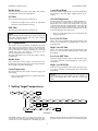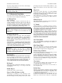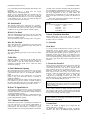
1
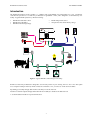
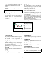
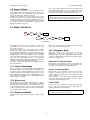
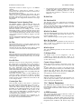
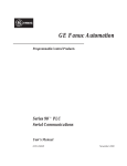
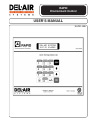
RAPID
Environment Control
USER'S MANUAL
RAPID-3M6
User Manual Ver3M6
RAPID Environment Control
Introduction
The RAPID Environment Control System is a complete, fully programmable and networkable two zone agricultural
controller. The system uses a revolutionary architecture in agricultural control, and is designed to accommodate any size
facility. A typical RAPID system may offer the following:
•
•
•
•
•
RAPID Environmental Control
RAPID Device Module(s)
RAPID-PC Monitoring Package
RAPID Temperature Sensor
Sensaphone® Auto-dialer Alarm package
RAPID
Environment Control
Model RAPID
Alarm / Warning Indicator
1
2
3
4
5
6
7
8
9
0
+/-
120/240 V, 50/60 Hz
0.2/0.1 A, 24 VA
S
Y
S
T
E
M
ESC
Room
Ambient
OK
®
Made in Canada
NRTL /C
S
LR 108984
Creep
Figure 1 - Typical RAPID Control Setup (1 Zone Only).
RAPID’s revolutionary architecture is designed to economically control any size facility, from 2 to 128 zones! The system
uses a simple twisted-pair network, which connects the controller to a PC, as well as its “smart” device modules.
Expanding your facility? Simply add another controller(s)† to the PC network.
Need more controller outputs? Simply add another device module(s)† to the device module network.
† See the Installation Guide for expansion limitations.
1
User Manual Ver3M6
RAPID Environment Control
Introduction______________________________________________________________________1
First Time Installation Hints _______________________________________________________3
1
2
Panel Features _________________________________________________________________4
Menu Information ______________________________________________________________4
2.1 Zone Selection_____________________________________________________________________________________________________ 4
2.2 Area Selection ____________________________________________________________________________________________________ 4
2.3 Editing Parameters ________________________________________________________________________________________________ 4
3
Key Descriptions _______________________________________________________________5
4
Viewing Temperature and Alarm Data_____________________________________________6
5
Ventilation Programs____________________________________________________________6
5.1 The Ventilation Program ___________________________________________________________________________________________ 6
5.2 Empty Room Program _____________________________________________________________________________________________ 7
5.3 Monitor Program _________________________________________________________________________________________________ 7
6
Timed Outputs _________________________________________________________________7
6.1 Timed Events _____________________________________________________________________________________________________ 7
6.2 Cycled Event______________________________________________________________________________________________________ 8
7
Setting Target Temperatures ______________________________________________________8
7.1 Fixed Target ______________________________________________________________________________________________________ 9
7.2 Step-Day _________________________________________________________________________________________________________ 9
7.3 Target Setback ___________________________________________________________________________________________________ 10
8
Testing The Control And Modules ________________________________________________1 0
8.1
8.2
8.3
8.4
8.5
8.6
9
Configuring the Sensors ________________________________________________________1 2
9.1
9.2
9.3
9.4
9.5
10
Mechanical Ventilation ____________________________________________________________________________________________ 11
Heater __________________________________________________________________________________________________________ 11
Natural Ventilation _______________________________________________________________________________________________ 11
Timed Outputs ___________________________________________________________________________________________________ 11
Alarm Test ______________________________________________________________________________________________________ 12
CPU Test________________________________________________________________________________________________________ 12
Sensor Descriptions _______________________________________________________________________________________________ 12
Calibrating Sensors _______________________________________________________________________________________________ 12
Factory Calibration _______________________________________________________________________________________________ 12
Auto-Calibrate ___________________________________________________________________________________________________ 12
Sensor Failures ___________________________________________________________________________________________________ 13
Alarm Functions _____________________________________________________________1 3
10.1
10.2
10.3
10.4
11
System Menu ________________________________________________________________1 4
11.1
11.2
11.3
11.4
11.5
11.6
12
Miscellaneous Parameters ________________________________________________________________________________________ 14
Mechanical Ventilation ___________________________________________________________________________________________ 15
Natural Ventilation ______________________________________________________________________________________________ 16
Control Parameters _____________________________________________________________________________________________ 17
Network Address ________________________________________________________________________________________________ 18
Reboot _________________________________________________________________________________________________________ 19
Setting up Security ___________________________________________________________1 9
12.1
12.2
12.3
12.4
12.5
13
Alarm Acknowledge _____________________________________________________________________________________________ 13
Alarm Level ____________________________________________________________________________________________________ 13
Enable and Disable _______________________________________________________________________________________________ 13
Emergency Mode________________________________________________________________________________________________ 13
Using The RAPID With PIN Enabled________________________________________________________________________________ 19
Setting up PIN___________________________________________________________________________________________________ 19
Changing PINs __________________________________________________________________________________________________ 20
Deleting PINs ___________________________________________________________________________________________________ 20
PIN Logs _______________________________________________________________________________________________________ 20
Control Strategy _____________________________________________________________2 0
13.1 – PID Explanation ________________________________________________________________________________________________ 20
13.2 Typical Control Operation _________________________________________________________________________________________ 20
Appendix A – Module Addressing ___________________________________________________2 1
2
User Manual Ver3M6
RAPID Environment Control
First Time Installation Hints
It is recommended that for a new installation the user first read over the entire manual to become familiar with the features
of the RAPID control. Then proceed with the steps listed below to configure it for your site.
1
2
3
4
5
6
7
8
9
The first step is to test every device connected to the RAPID to make sure it is able to control each device
properly. Section 8 Testing The Control And Modules describes how to test each of the devices.
Restore the Factory Settings for the control by pressing the button marked “System” and then press OK when
it
shows
1)
Misc.
Now
press
the
up
arrow
button
so
that
it
shows
4) Factory Preset and then use the arrow button to verify that you want to do it and press OK.
Configure the control for what ventilation equipment is connected to it and when to use it. This is
accomplished by configuring the System Menu parameters. Refer to Section 11.
Configure the Temperature Sensors. This is dealt with in Section 9 Configuring the Sensors.
After the Temperature Sensors are operating, the Target Temperature needs to be set. Section 7 Setting Target
Temperatures deals with setting the Target Temperature.
Once the Target Temperature is set you have to tell the RAPID which Ventilation Program to use to get it
there. Section 5 Ventilation Programs shows the different programs available to use
Enable alarms so that any emergencies can be reported. Section 10 Alarm Functions describes the Alarm
Menu. Alarms include high or low temperature, sensor failure and power failure.
Set up the Timed and Cycled Events if they are being used. Section 6 Timed Outputs shows how to set up both
of these. This could include lights, feed systems in the Timed Events and spray/drip cooling for the Cycled
Event.
The last setting to check is the PIN Access. The control comes with the security off but the manager may set
this up to make sure only responsible personnel are making changes to the settings. Configuring PIN is
described in Section 12 Setting up Security.
The Chapters are set up in the order of the buttons so that finding information will be easier. As such, the chapters do not
follow the above order.
HINT:
Throughout the manual are flowcharts to help guide you through the menus. To see how to navigate through the menus
please read through Section 2 Menu Information.
3
User Manual Ver3M6
RAPID Environment Control
Table 1
1 Panel Features
•
The RAPID Control’s 2-line LCD display and full
16-button keypad provide a simple and user friendly
interface to all programmable features of the system.
•
The panel has a visible alarm indicator to alert the
user if any alarm conditions exist.
•
All function keys double-up as numeric keys for
simple changes to target temperatures, fan speeds, etc.
This symbol indicates that the
arrows can be used to select an
item from a list.
This symbol indicates that a
number is to be entered using the
number keys.
This symbol is used when no
input is required from the user.
Display only.
RAPID
DEL-AIR Systems
01-12-95 12:00PM
Environment Control
Model RAPID
This symbol shows sub-menu
names. The arrow keys are used
to pick the submenu desired.
Alarm / Warning Indicator
Temp
1
Vent
4
Test
7
Max/Min
Events
2
3
Timer
Target
5
6
Sensor
8
System
0
ESC
2.1 Zone Selection
Alarm
OK
120/240 V, 50/60 Hz
0.2/0.1 A, 24 VA
S
Y
S
T
E
M
Each control is capable of controlling two separate
zones or rooms. Therefore, when a function key is
pressed, the system asks for the zone to be displayed or
programmed. The zones are defined as Zone 1 and Zone 2.
Using the up/down arrow buttons toggle between the
zones and pressing OK selects the zone shown on the
display.
9
+/-
S
Made in Canada
®
NRTL /C
LR 108984
Figure 2 - RAPID Control Panel
2.2 Area Selection
If sensor 2 is enabled as a creep sensor, the control will
ask which area (zone or creep) is to be displayed or
programmed in the chosen Zone when a function key is
pressed. Choosing the area is identical to the Zone
Selection, pressing the up/down arrow buttons will
toggle between Zone and Creep. Pressing OK will then
select the area shown.
2 Menu Information
The RAPID Control has its main menus built in to the
function keys on the face of the controller. Each of these
menus or “function” keys has sub-menus that are
displayed on the display. The function keys are of two
different types:
1)
2.
2.3 Editing Parameters
Display Functions
Program Functions
When you have followed a flowchart to the point that
you are at one of the parameters to set, this is how you
make the changes.
To change a parameter setting, press...
1. Numeric keys 0 - 9 to enter desired number
(Pressing the +/- key can be used to enter a negative
value into a field such as when entering sensor
offsets.)
Function keys 1-3 are display functions only. There is no
programmable data within these functions. Function keys
4 - 0 each contain sub-menus that contain all
programmable features in the system.
Each of the programmable function keys has an
accompanying flowchart in the manual to make it easier
to navigate through and set up. To follow the flowchart
press OK to move to the right and press the up/down
arrows to move up and down in the flowchart.
The flowcharts use the following four symbols. Table 1
shows the symbols and describes what they mean.
or
2.
4
press the up/down arrows to increase/decrease the
numeric field or to toggle between states such as On
and Off.
Press OK, this locks the value into memory or sends
the command, pressing ESC will disregard the
change and keep the original data.
User Manual Ver3M6
RAPID Environment Control
3 Key Descriptions
The table provided below describes the function of each of the keys on the front panel of the control. Keys 0-9 are used as
both numeric keys and function keys.
Table 2
Key
Temp
1
Min/Max
2
Recall
3
Vent
4
Timer
5
Target
6
Test
7
Sensor
8
Alarm
9
System
0
Description
Displays present Target Temperature and Actual Temperature for the Area chosen as well as the
Ambient Temperature.
Displays the minimum and maximum temperatures since midnight for Zone, Creep (when enabled) and
Ambient.
Displays a list of recorded alarms.
Changes the Ventilation Program that the controller is running. (Ventilation, Empty Room
Monitor)
or
Edits and enables different Timer functions such as lighting or feeding as well as the Cycled Event for
spray/drip cooling.
Used to set the Target Temperature for the Zone and Creep areas.
Allows the user to manually turn on a device or inquire the device’s status. This is used to verify that
all modules are responding properly to the RAPID’s commands.
Allows the user to enable or disable sensors and fine tune sensor readings.
Used to acknowledge alarms.
Edits and enables the alarm for the Zone and Creep Areas.
Sets up the RAPID’s internal configuration and preferences.
ESC
Escapes to the home menu (See Figure 2 - RAPID Control Panel).
Exits fields without saving changes.
OK
Selects a sub-menu option.
Saves all program and numeric field changes.
Press to enter Personal Identification Number (PIN) to gain access to control.
Enable/disable, add/remove PINs etc.
Scrolls through sub-menus
Increases/decreases numeric values.
5
User Manual Ver3M6
RAPID Environment Control
4 Viewing Temperature and
Alarm Data
Temp
4.1 Current Temperature
1
Viewing
Recall
3
This displays when and which alarms have occurred in
the chosen zone. These logs are kept for an indefinite
amount of time.
Alarms include the following conditions:
•
High Temperature Alarm
•
Low Temperature Alarm
•
Bad Sensor
•
Alarm acknowledgment
•
Alarm Off
After pressing this key and selecting the zone, the screen
will display the Zone’s current Target and Actual
Temperature in the temperature scale selected in the
System Menu. Pressing the up/down arrows will scroll
to the Ambient temperature, Creep temperature if Sensor 2
is enabled as Creep or show each sensor individually if
both sensors are enabled as zone.
Min/Max
2
4.3 Recalling Alarm
Data
Logs for each area of the zone are kept in separate logs
so each area of each zone can be viewed independently.
Using the up/down arrows will scroll through the logs.
4.2 Min/Max Temp
Viewing
This allows the user to view the maximum and minimum
temperatures of the Zone, Creep and Ambient sensors
since midnight of the current day. Pressing the up/down
arrows will display Zone, Creep and Ambient
temperatures.
5 Ventilation Programs
Vent
4
Select Zone
1) Ventilation
Step or Fixed
Min Vent
0, 1, 2, 3
Stages
Step
Enable Tunnel
Enable Nat Vent
Program
Running
Fixed
Minimum
Vent (CFM)
2) Empty
Room
Enable
Fan?
3) Monitor
Program
Running
Yes
Minimum
Vent (CFM)
Program
Running
No
Flowchart 1
There are three different programs that the user can
choose from to control the ventilation in each zone. This
section describes the programs and how to use each one
of them.
Flowchart 1 shows the menu steps for running the
ventilation programs
A) Step or Fixed Min Vent
If the Step Day Program is running you can choose to use
the Fixed Min Vent or Step Day Min Vent.
This can be changed at any time during the program.
When changed from fixed to step, it automatically sets the
min vent to the current day’s value as set by the step day
program. When changed from Step to Fixed the control
next asks for the fixed min vent rate.
The programs are automatically started when all
parameters have been OK’d. A confirmation message will
VENTILATION PROGRAM
be displayed, for example “V
RUNNING”. If the confirmation message has not appeared
the control will still be running the previous program.
Only one of the three programs can run at one time.
Therefore, when a new program is selected, the previous
running program is automatically disabled.
B) Fixed Min Vent Rate
This is the least amount of air ever to be moved through
the room, even when the room temperature drops below
Target. It is entered as a percentage of the Stage 0 and
Stage1 fans ventilation combined.
e.g. Stage 0 moves 2000CFM and Stage 1 moves 4000
CFM. If the room requires a minimum ventilation rate of
1500 CFM, the min vent would be 1500/6000=25%.
5.1 The Ventilation Program
The Ventilation Program should be used whenever there
are animals in the room. It is designed to operate all the
ventilation equipment that has been installed in the zone
to control the room temperature.
C) Number Of Stages Enabled.
It may be desirable to disable some stages of exhaust fans
in different seasons or when small animals are in a room.
This setting allows you to choose how many stages of
exhaust fans you want enabled.
The ventilation program uses the following settings:
6
User Manual Ver3M6
RAPID Environment Control
The Empty Room Program is used when a room needs
either no ventilation or no more than the first stage fan to
ventilate a room. The heater is still enabled to keep the
room up to the target temperature.
Since the room is empty it also disables natural
ventilation, tunnel, stir fan, timed events, the cycled event
and creep heat. If the control was in Natural Ventilation
or Tunnel mode when the Empty Room Program was
started, it immediately returns to Mechanical mode.
The Empty Room Program uses the following settings:
The up/down arrows are used to select 1, 2 or 3 stages
enabled. Stage 0 is included if enabled.
•
Fans can only be enabled if they are installed in the
System menu.
IMPORTANT:
It is very important that a fan stage be disabled in the
control if it is not installed or not operational in the
ventilation setup.
The RAPID control uses a unique control strategy to
maintain the target temperature. All stages of ventilation
and heater are combined to control to one target
temperature. This has been accomplished using a control
technique called “PID”. The control uses PID to
automatically calculate a ventilation rate for the zone as
the temperature deviates from the Target Temperature. If
a stage is enabled but not plugged in, the control may still
try to run only that stage and shut off the other stages.
This could result in temporary moments of minimal
ventilation until the temperature rises and other
available fans could come on.
A) Enabled Fan?
The stage 1 fan (with stage 0 if enabled) can be either
enabled or disabled. The up/down arrows toggle
between Yes and No.
The Heater will always remain active to keep the room at
the Target Temperature but the fan can be disabled to
keep from exhausting warm air outside.
B) Min Vent Rate
The Step Day Min Vent program is automatically
disabled so it will ask the Fixed Min Vent to use.
(See description in Section 5.1B - Ventilation Program)
C) Enable Tunnel
5.3 Monitor Program
If Tunnel has been enabled in the System Menu, the
option of using it for the current program is available.
Use the up/down arrows to select ENABLED or
DISABLED .
This program is used only for testing purposes or in an
emergency if all devices in a zone need to be shut off
immediately.
D) Enable Nat Vent
NOTE:
Monitor Program disables and stops all devices
connected to the RAPID except for the Timed and Cycled
Events. This program is used only for testing or for
emergency.
If the Natural Ventilation has been enabled in the System
Menu, the option of using it for the current program is
available.
Use the up/down arrows to select ENABLED or
DISABLED .
5.2 Empty Room Program
This program should be run only when there are no
animals in the selected zone.
6 Timed Outputs
Timer
5
Select Zone
1) Timed
Events
Timer Number
Event Number
Enable Event?
Yes
ON Time
HH:MM
OFF Time
HH:MM
Cut Out Temp
Low ON Time
NO
2) Cycled
Event
Enable Event? Yes
Cut In Temp
Cycled Event
Band
High ON Time
Low OFF Time
High OFF Time
Main Screen
No
Flowchart 2
The RAPID has two types of timed outputs.
The first type is TIMED EVENTS This turns devices on
and off at certain times of the day. The RAPID control
contains three timed outputs per zone. Each output can
turn on and off eight times per day to accommodate such
outputs as feed systems and lights.
6.1 Timed Events
This section describes each setting to set up the Timed
Events.
Timer Number
The second type is the CYCLED EVENT. This cycles a
device on and off only when the temperature is above (or
below) a configurable temperature. The RAPID has one
Cycled Event per zone. This Event is commonly used for
spray/drip cooling.
Use the up/down arrows to select which of the three
timers to select.
Event Number
Use the up/down arrows to select which of the eight
events of the chosen timer to program.
Flowchart 2 shows the menu steps for setting up the timed
outputs.
7
User Manual Ver3M6
RAPID Environment Control
Enable Event
Cycled Event Band
Not all events need to be used on each timer. This enables
or disables the event for the selected timer.
This is the number of degrees above the cut in temperature
that it takes to reach the “high” settings from the “low”
settings.
ON Time
Cut Out Temperature
This is the time of day the device will turn on.
•
The temperature the event will stop cycling and shut off.
If you want the Cycled Event to run when the room
temperature is above the Cut In Temperature (eg Spray
Cool) then make the Cut Out Temperature lower than the
Cut In. If you want the Cycled Event to run when the
room temperature is below the Cut In Temperature, set the
Cut Out Temperature above the Cut In.
Each timer has eight events so there are eight times
the device can be turned On each day.
OFF Time
This is the time of day the device will turn off.
•
This is an actual temperature, not a band set from the
target for the room.
NOTE:
When entering Time into the RAPID you type in the hours
then “OK”, then the minutes and “OK”. Time must be
entered in the 24 hour format.
Low Cycle ON Time
6.2 Cycled Event
This is how long, in minutes and seconds, that the event
will stay on for when the room temperature is at the Cut
In Temperature.
The cycled event is proportional, meaning that the event
will engage and start cycling at the Cut In Temperature
and as the temperature rises (or lowers), the on and off
times go from the low settings gradually up to the high
settings. This allows the cycling to occur more or less
often as temperature rises (or lowers).
This section describes how to set up the control to use the
Cycled Event.
High Cycle ON Time
This is how long, in minutes and seconds, that the event
will stay on for when the temperature has reached the
Event Band.
Low Cycle OFF Time
This is how long, in minutes and seconds, the device will
stay off for when the room temperature is at the Cut In
Temperature.
Enable Event
This is where the control is told to use the event or not.
Disabling the event will stop it from activating even if the
device is still connected to the RAPID.
High Cycle OFF Time
This is how long, in minutes and seconds, the device will
stay off for when the room temperature has reached the
Event Band
Cut In Temperature
The temperature that the cycled event will engage and
start cycling.
•
NOTE:
When entering Cycle On/Off times into the RAPID you
type in the minutes then “OK”, then the seconds and
“OK”.
This is an actual temperature, not a band set from the
target for the room.
7 Setting Target Temperatures
Select Zone
Select Area
1) Fixed
Target
Target
Temperature
Main Screen
2) Step Day
1) Status
Status
Displayed
2) Edit
Program
Temp Program
Days
Temp Ramp
Days
3) Start
Program
Program
Running
Main Screen
Setback
Degrees
Start
Time
3) Target
Setback
Enable Event?
Yes
Start
Temperature
Final
Temperature
End
Time
Main Screen
Min Vent
Program Days
Final
MinMinimum
Vent
Ramp
Vent
Days
Start
Final Minimum
Minimum
Vent
Final Minimum
Vent
No
Flowchart 3
The RAPID control is able to monitor and control two
areas per zone, the Zone (room) and the Creep Area. The
control also has two temperature controlling programs
built into the system; these are Fixed Target and Step Day
programs. Each area in each zone can use either program
8
User Manual Ver3M6
RAPID Environment Control
7.2 Step-Day
to set its Target Temperature. These two programs can
also be supplemented by the Target Setback program.
This section describes and shows how to use each of the
programs.
This program is used to automatically change the target
temperature and min vent over a specified growth period.
When configuring the step day program for the creep area
the parameters for min vent are omitted since min vent
applies to the zone only, not the creep.
Once Step Day is selected the first step is to edit the
program. After the parameters are set, the program must
then be started to enable the program.
If the same parameters are used each time it is not
necessary to edit the program each time before starting it
when the animals are put into the room the program only
needs to be started again. If the step day program is used
for the zone and creep areas you must start each step day
program individually.
If a step day program is running and you want to view
the current day of the program, what the min vent is or
the current target, you can select the Status menu item in
the Step Day menu. The initial screen displays the min
vent program status, pressing the down arrow will
display the temperature program status.
Figure 3 shows the temperature parameters that are used
to develop the growth curve:
Flowchart 3 shows the menu steps for setting the Target
temperature.
NOTE:
If Sensor 2 is not enabled as Creep for the current zone,
Creep will not show up in the Target menu.
7.1 Fixed Target
Fixed Target is used when the target temperature for the
zone does not need to change over a period of time. The
temperature entered stays the same until another
temperature is set.
Once selected, enter the desired target and press OK to
save to memory.
3
Temp (°C)
40
1 Program Days: 0-99
2
0
Days
2 Ramp Days: 0-99
4
3 Start temperature
99
1
4 Final temperature
Figure 3
Temp Program Days
Vent Program Days
The total number of days that the Temp Step Day program
runs, including the initial time it keeps the temperature
constant as well as the time it will ramp the temperature.
After the number of program days have passed the
temperature will remain at the final temperature.
Is identical to the Temp Program Days but is used for the
Ventilation Step Program to ramp the Minimum
Ventilation.
Temp Ramp Days
Is identical to the Temp Ramp Days but is used for the
Ventilation Step Program.
Vent Ramp Days
The number of days the control will ramp the room
temperature from the start to final. By making the ramp
days less than the program days, an initial higher
temperature can be maintained in the room during the
early periods of the animal’s growth.
The temperature steps are automatically calculated and
updated in the system at midnight.
Start Minimum Vent
The min vent (see page 6) desired when the program is
first started.
Final Minimum Vent
The min vent desired when the program is finished.
Start Temp
The Target Temperature desired when the program is
first started.
IMPORTANT:
Changing the date while the step-day program is running
will move the program back or ahead and change the
Target and Min Vent accordingly.
Final Temp
The Target Temperature desired when the program is
finished.
9
User Manual Ver3M6
RAPID Environment Control
The following example shows how the growth curve may
be setup.
E.g.)
vent will be at 25% of Stage 1 for the first 7 days and
will ramp up to 100% of Stage 1 for the remaining 3 3
days. The target will hold constant at 20.0°C after the 2 8
days but the ventilation will continue to increase for the
entire 40 days.
SYSTEM DISPLAY
TEMP PROGRAM DAYS
TEMP RAMP DAYS
START TEMP
FINAL TEMP
VENT PROGRAM DAYS
VENT RAMP DAYS
START MIN VENT
FINAL MIN VENT
28
21
25.0°C
20.0°C
40
33
25%
100%
7.3 Target Setback
This feature is can be used when a reduced target
temperature is desired during a portion of the day. This
program will reduce the Target Temperature whether it is
set by the Fixed Target or the Step Day Program.
The Target Temperature will be reduced by the set
number of degrees from the Start Time to the End Time.
After the End Time it will return the Target to its original
temperature.
In this example the growth cycle is 40 days. This program
will operate such that the room temperature is
maintained at 25.0°C for the first 7 days and then will
automatically ramp down to 20.0°C for 21 days. The min
8 Testing The Control And Modules
Test
7
Select Zone
1) Mechanical
Vent
Fan Stage X
% On
OK
Or
ESC
OK
Or
ESC
Either
5) Stir Fan
% On
Either
6) Tunnel
OK
ON or OFF
1) Stage 1
Or
ESC
Either
2) Stage 2
7) Cable
Inlet
% On
OK
Or
ESC
OK
Or
ESC
OK
OK
Or
ESC
OK
OK
Or
ESC
Or
ESC
Either
2) Heaters
1) Stage 1
ON or OFF
Either
2) Stage 2
ON or OFF
Either
3) Creep
% On
Either
3) Natural
Vent
Curtain Number
Open/Stop
Close/Stop
OK
OK
4) Timed
Outputs
1) Timed
Events
Timer #
ON or OFF
OK
Or
ESC
OK
Or
ESC
Either
2) Cycled
Events
ON or OFF
Either
5) Alarm
Test
OK
ON or OFF
Or
ESC
Either
6) CPU Test
Display
Result
Main Screen
Flowchart 4
The Test feature serves two purposes. First, it is used to
manually turn on and off any of the devices connected to
the RAPID Control. Second, it allows the user to find out
what the RAPID Control is telling each device to do.
To get the RAPID to display what each device is
supposed to be doing, do not put the control in Monitor
Program. When you press Test it will warn you that you
can not make changes to the devices by showing the
message:
To manually test the devices the control must first be put
into Monitor Program. Once in Monitor you can use Test
to manually control fans, heaters, inlets, curtains, alarm
outputs, as well as perform internal controller checks.
These tests may be performed to ensure that all devices
are functioning properly.
Devices turned on or off during testing will remain in
that state until either the Ventilation or Empty Room
program is again started.
ZONE X NOT IN MONITOR PROGRAM
Pressing OK at this point will allow you to enter the Test
Menu to view the status of the devices. Now you may
choose any of the devices and the RAPID will show you
what that device has been told to perform.
This is a one-time display. It will not update the screen if
the device changes after it has displayed the status. To
update the display you must press ESC and test the device
again.
10
User Manual Ver3M6
RAPID Environment Control
8.2 Heater
Flowchart 4 shows the menu steps for running the tests.
The Heater test will test the heaters in both the Zone and
Creep areas.
NOTE:
To manually turn devices on and off the control must be
in MONITOR program. To do this, select the monitor
program as shown in Section 5 Ventilation Programs. If
the zone is not put in Monitor Program the control will
continue to operate the equipment and will override any
changes you try to make.
A) Stage 1 Heater
The Stage 1 heater is the primary room heater.
If the heater has been configured in the System Menu as
proportional this menu will work similarly to the stage 1
fan. If it is not configured as proportional, the up and
down arrows will toggle the state from Off to On and
back. After a state has been chosen the OK key must be
pressed to send the command to the device.
When done testing, pressing the ESC key will take you
back to the main menu.
8.1 Mechanical Ventilation
A) Stages 0 to 3
B) Stage 2 Heater
A variable speed test may be performed on ALL stages of
exhaust fans. Manually enter the desired speed of the fan
(between 0 and 100%) and press OK. After OK is pressed
another value may be entered and OK’d, this can be done
repeatedly. When finished testing a fan, press ESC to get
back to the main menu.
This test is particularly useful for determining the
minimum safe operation of the fan that is to be speed
controlled.
The Stage 2 heater is either the higher output mode on the
primary heater or is physically a second room heater.
The test operates similarly to the Stage 1 Heater
described previously.
C) Creep Heater
The Creep heater test works the same as testing a
variable speed fan since the RAPID is capable of
proportional control of heat lamps, etc.
See page 11.
NOTE:
The Test menu will allow Stage 3 to be tested as a
variable speed fan. If your Stage 3 fan is not able to
operate variable speed (e.g. belt drive fan) you should use
only 0% and 100% to test the fan.
8.3 Natural Ventilation
This test allows the user to manually tell the curtains to
move up, move down, and stop. It also will show the
current position of the curtain if the control is not in
Monitor Program.
NOTE:
Any value less than 15% will be assumed to be 0%. The
RAPID will never try to run a fan at less than 15% speed
as most fans will move very little air at this slow speed.
•
A) Curtain Number
The up/down arrows or the number keys can be used to
select the curtain number. When the proper number is on
the screen, press OK.
When ESC is pressed, the fan will continue to run at
the last speed entered in the test. Normal operation
will start when either the Ventilation or Empty
Room Program is started.
B) Open/Stop/Close
The top line displays the percentage of full open if the
control is running either the ventilation or empty room
programs. If in monitor program it will show ???% since
the control can’t know where the curtain is.
The up/down arrows will toggle the display between
OPEN, STOP, CLOSE, STOP. After the proper one is on
the display press OK to send the commands to the curtain.
When done testing press ESC to get back to the main
screen.
B) Stir Fan
This allows for testing of the Stir Fan.
To test, enter the desired speed and press OK to send the
command to the fan. Press ESC to return to the main menu
when done.
C) Tunnel
This test manually runs the Tunnel Fans and Tunnel
Curtain.
First select stage 1 or stage 2 by using the up/down
arrows and press OK. Then use the arrows to select off
or on and press OK. Like the previous tests, you can send
repeated commands by pressing the arrows and OK again
to send the command.
To leave, press the ESC key.
IMPORTANT!
Always STOP the curtain before changing its direction.
Failure to do so may result in damage to the curtain
and/or actuator motor.
8.4 Timed Outputs
D) Cable Inlet
This tests to see if the Timed Events and Cycled Events
respond properly.
The inlet will open to the percentage that is entered. A
number must be entered and the OK button pressed. To
leave the test, press the ESC key.
•
A) Timed Events
To test the module, first choose the proper timer (1 to 3).
Use the up/down arrows to select the proper timer and
press OK. After the timer is chosen use the arrows to
select On or Off and press OK to send the command.
Pressing ESC takes you back to the main menu.
Refer to the Installation Guide Section 7 for
instructions on setting up the cable inlets
11
User Manual Ver3M6
RAPID Environment Control
B) Cycled Events
IMPORTANT
Make sure the Alarm is off before leaving. If left on, the
alarm contacts will stay on after the test is over.
The test operates identically to the Timed Events in page
11
8.5 Alarm Test
8.6 CPU Test
This feature tests the alarm contacts to ensure that they
are operational. Use the test to activate either a local
siren or central auto-dialer. The Alarm LED on the
RAPID panel will light when the alarm condition is ON.
When in the “Alarm Test” screen, use the up/down
arrows to toggle On or Off and OK to initiate the
command.
This is an internal test of the controller. When OK is
pressed the display should show the software version
number if the test has passed. If the display shows an
error number the test has failed. Should the test fail,
please note the error number and consult your dealer.
9 Configuring the Sensors
Sensor
8
1) Zone 1
1) Sensor 1
Enable
Sensor?
2) Sensor 2
Enable
Sensor?
Yes
Offset
Main Screen
Yes
Zone or
Creep
Offset
No
2) Zone 2
Main Screen
No
3) Ambient
Enable
Sensor?
Offset
Yes
Main Screen
No
4) Factory
Preset
Verify
Main Screen
5) Cable
Auto
7)
Calibrate
Inlet
Auto
Calibrate?
Main Screen
Flowchart 5
Last is the sensor calibration itself. The control measures
what the sensor is reading and shows it as its Nominal
reading. If this temperature is not quite correct you can
fine tune it with the Offset. Enter the offset so that the
Nominal reading plus the offset gives the real room
temperature.
Each RAPID control has inputs for five sensors; one
Ambient Sensor and two sensors for each zone.
Flowchart 5 shows the menu steps for configuring the
sensors.
9.1 Sensor Descriptions
NOTE:
If no sensors have been enabled in a zone, the
temperature for the zone will give a reading of -100°C (147°F)
Sensor 1
Sensor 1 can only be used to measure the Zone (room)
temperature.
NOTE:
When multiple controls are at a site, they can be
networked together so that only one control needs to
have an ambient sensor. With or without a computer
attached, the Ambient Temperature will be broadcast
across the network to the other controls. Only enable the
ambient sensor on the control with the ambient sensor
connected to it, all other controls should have the
ambient disabled.
Sensor 2
Sensor 2 may be used to average with Sensor 1 for the
Zone temperature, or it may be set to measure temperature
for the Creep area.
Ambient
The Ambient Sensor is used to measure the temperature of
the outside air that is used to supply fresh air to the zone.
9.2 Calibrating Sensors
9.3 Factory Calibration
After a sensor is chosen (1, 2 or Ambient) it will ask if
the sensor is to be enabled. Use the arrows to answer Yes
or No.
If sensor 2 is enabled it will ask if it should be enabled as
a Zone sensor or a Creep sensor. Use the arrows to
choose which area it will be measuring.
This menu option sets all the offsets back to zero.
9.4 Auto-Calibrate
With this enabled the control constantly monitors the
sensor calibration and automatically adjusts it to keep
the sensor reading accurately.
12
User Manual Ver3M6
RAPID Environment Control
9.5 Sensor Failures
Once a sensor has gone bad you must fix the problem and
then reboot the control for it to recognize the sensor
again. The control will not recognize that the problem
has been fixed until the control has been rebooted.
If there is only a single sensor in an area and that sensor
goes bad the control will no longer be able to monitor the
temperature in the room. When this occurs the control
will go into Emergency Mode (see page 13).
If there are two sensors in an area and one sensor goes
bad, the control will go into alarm but will automatically
ignore the bad sensor and run the ventilation off the one
good sensor. If both sensors go bad in the area the control
is not able to monitor the temperature and will go into
Emergency Mode (see page 13).
NOTE:
After a sensor has been repaired or replaced the control
must be rebooted for it to quit calling the sensor bad.
10 Alarm Functions
Alarm
9
Select Zone
1)Acknowledge
Main Screen
2) Alarm Set
Alarm
Level
Enable
Zone?
Enable
Creep?
Main Screen
Flowchart 6
Both areas will have the same level for the alarm, but
each area can be enabled separately.
The RAPID control has a visual indicator on the front
panel and two relay contacts, which are used to alert
personnel of an alarm.
The control takes into consideration the Ambient
Temperature when giving alarms. If the target for a room
is 20°C and the alarm band is 5° an alarm would occur if
the temperature in the room exceeded 25°. If the Ambient
Temperature is 23° the alarm realizes that the room temp
may not be able to be under 25° so it won’t give an alarm
until the room temperature reaches 28°. When the
Ambient Temperature is above the target temp, the alarm
band moves up with the Ambient Temperature.
Flowchart 6 shows the menu steps for stepping through
the Alarm submenus.
10.4 Emergency Mode
When the control is no longer able to read the
temperature of the room the control will go into
Emergency Mode Operation. Depending on the mode the
control was in before the failure the control will respond
in the ways listed below.
Mechanical Ventilation Mode
If the failure occurs when the control was running only
the exhaust fans and/or heater, the control will run only
the Stage 1 fan (and Stage 0 if installed) at 100%.
10.1 Alarm Acknowledge
Once an alarm has occurred, it must be acknowledged for
the alarm condition to be cleared, with the exception of a
power loss alarm. Acknowledging will clear the alarm
and de-activate it for 15 minutes, allowing time to correct
the problem that caused the alarm. If the problem has not
been corrected 15 minutes after acknowledgment, the
alarm will be re-activated.
Natural Ventilation Mode
If the failure occurs when the control has the natural
ventilation curtain(s) open, the control will leave the
curtains and fans running exactly as they were before the
failure occurred.
If the curtains are open only at their minimum opening,
the control will open them a single run time to allow
adequate airflow through the room.
10.2 Alarm Level
The Alarm Level is the number of degrees above or below
target at which an alarm will occur. An alarm condition
will light the Alarm indicator on the RAPID panel and
close the alarm contacts to activate an auto-dialer alarm
system, as well it sends an alarm condition to the RAPIDPC software if it is installed.
Tunnel Mode.
If the control was operating the tunnel fans when the
failure occurred, the control will leave the tunnel fans
running and turn on all exhaust fans.
Once the control has entered emergency mode it must be
rebooted to return to normal operation.
10.3 Enable and Disable
The Zone and Creep areas have separate enables for the
Alarm.
13
User Manual Ver3M6
RAPID Environment Control
11 System Menu
System
0
1) Misc
2) Mech
Vent
1) Temp
Unit
C or F
2) Clock
Clock Set
3) Calendar
Calendar Set
3) Factory
Preset
Reset all
Parameters
Zone
Yes
Sure?
No
No
1) Exhaust
Fans
Stages
Installed
Yes
Stage 1
Min Fan Speed
Stage 2
Min Fan Speed
Fan
Breakfree
Heat Exchanger
or Fan
Stage 0
Size
Minimum
Speed
Yes
Low Tunnel
Band
High Tunnel
Band
Tunnel
Stages Enabled
Yes
Min Stir
Band
Max Stir
Band
Minimum
Speed
2 Sets
Installed
1) Curtain 1
Curtain Band
Minimum
Opening
On Time
Idle Time
Fast
Idle Time
Curtain Open
Time
2) Curtain 2
Curtain Band
Minimum
Opening
On Time
Idle Time
Fast
Idle Time
Curtain Open
Time
3) Curtain 3
Minimum
Opening
On Time
Idle Time
Fast
Idle Time
Curtain Open
Time
4) Curtain 4
Minimum
Opening
On Time
Idle Time
Fast
Idle Time
Curtain Open
Time
Enable Stage
Yes
0
2) Stage 0
Main
Screen
No
3) Tunnel
Installed?
Close Inelts?
No
4) Stir Fans
Installed?
No
5) Cable Inlet
3) Natural
Vent
Zone
Installed
Yes
Minimum
Opening
Inlets Open
at x% of St1
1) Curtains
Dead Band
No
Installed?
2) Stir Fans
4) Control
Parameters
Zone
Min Stir
Fan Band
3) Exhaust
Fans
Curtain 1
Stages Enabled
Curtain 2
Stages Enabled
1) PID
Parameters
Proportional
Set
Integral Set
Derivitive Set
2) Heater
Proportional
Zone?
Minimum
Heat
S1 Heat
Control Band
Yes
S2 Heat
Installed?
No
3) Other
5) Net
Address
Enter
Address
6) Reboot
Restart?
Sample
Period
Min Fan
Speed
Max Stir
Fan Band
Yes
S2 Heat
Control Band
No
Switch Time
Creep
Variable?
Yes
Minimum
Heat
No
Switch Band
Main Screen
Flowchart 7
All system parameters, which are typically a one-time
setup, are contained in this menu.
B) Clock
Flowchart 7 shows the menu steps navigating through the
System submenus.
The system uses a 24-hour clock. To enter time, enter hh,
press OK ...enter mm, press OK.
11.1 Miscellaneous Parameters
C) Calendar
This holds parameters that affect the display and Factory
Preset.
The calendar is displayed as dd-mm-yy. To enter
calendar, enter dd, press OK, then enter mm, press OK
and enter yy then press OK.
A) Temp Unit
D) Factory Preset
The temperature unit may be selected as either °F or °C.
Use arrow keys to select, press OK.
This resets ALL configurable parameters back to the
factory settings. When this is chosen, the control will be
configured the way it was when it was programmed at
14
User Manual Ver3M6
RAPID Environment Control
the factory. All parameters are reset. None of the changes
made at the site will be kept.
percentage of total air movement. When enabled as a fan,
stage 0 will continue to run even when stage 2 reaches
100%.
IMPORTANT:
Use of the Factory Preset should only be executed under
the direction of DEL-AIR.
Stage 0 size
Since stage 0 works with stage 1 to provide minimum
ventilation in the room the control needs to know how
big stage 0 is in relation to stage 1 so that it knows when
to use each fan to provide min vent.
This is entered at a % of stage 1 fan. If stage 1 is one 4 K
fan and stage 0 is one 2K fan then it would be entered at
50% of stage 1.
11.2 Mechanical Ventilation
This section deals with the setting up of all components
to do with forced air ventilation in the facility.
A) Exhaust Fans
Minimum Speed
Stages Installed
This is the number of stages of exhaust fans that are
actually installed in the zone and can be used for
maximum ventilation. The total number of stages installed
should be entered here. This does not include fans such as
stir fans or tunnel fans. Temporarily unused stages
should be enabled/disabled from the VENT menu.
This setting is similar to the Min Fan Speed found in the
Exhaust Fans menu of section 11.2 A.
C) Tunnel
Tunnel Ventilation is a ventilation strategy in which a
large amount of fan power is located at one end of a room
and a curtain is located at the opposite end. When tunnel
is engaged the curtain drops and the tunnel fans come on.
Air is pulled through the room as in a tunnel.
The RAPID provides two stages of tunnel, each with its
own temperature band at which it cuts in. The Low
Tunnel Fans cut in and the Tunnel Curtain opens at the
Low Tunnel Band and will run until the temperature
drops to half of that band. The High Tunnel Fans cut in at
the High Tunnel Band and cut out when the temperature
drops back to the Low Tunnel Band.
Stir Fans do not run in tunnel mode.
Note:
If a fan is simply unplugged or in need of repair it should
still be shown as installed here but disabled from the
VENT menu.
Minimum Fan Speeds
The minimum speed for the stage 1 and 2 fans must be
entered if they are installed. This is a fan protection
feature, as not all models of fans respond the same to
variable speed controls. Under no circumstances, other
than test, will the controller let the fans run slower than
these parameters.
This is entered as a percentage of full speed. The default
speed is 35%. It is recommended that this be adjusted once
installation is complete, so the fan to be speed controlled
can be supervised. The test feature of the control can be
used to find a suitable Minimum Fan Speed.
Low Tunnel Band
This is the temperature at which the first tunnel fans
come on and the tunnel curtain drops. It is entered as a
band from Target.
High Tunnel Band
This is the temperature at which the remaining tunnel
fans come on. If only one stage of tunnel fans is used, this
band should be set equal to the Low Engage Band.
Important
Minimum fan speed is not the same as minimum
ventilation rate. Min vent is the speed of the stage 1 fan if
the heater is running. When stage 2 starts to run stage 1
will initially drop to the min fan speed.
Exhaust Stages Enabled
Here you choose the stages of exhaust fans that you want
to run while the tunnel fans are running.
To choose which fans you want to run press the number
button of the stage on the keypad. To remove a stage,
press the number button of that stage again and it will
disappear. The chosen stages will appear on the display.
You can choose any combination of stages, they do not
have to be successive.
Fan Breakfree
When a fan is not moving and is then told to run slowly it
may stay stalled if it is blocked by ice or other debris.
This option helps the fan to start by giving the fan a
100% voltage burst for five seconds, it then returns the
fan to the speed at which the controller is requesting.
“YES” enables the burst and “NO” disables the burst.
Close Inlets?
This is the option of keeping cable controlled inlets open
or closing them when tunnel mode is entered.
Use the arrow keys to choose Yes to close the inlets or
No to keep them open.
B) Stage 0
Stage 0 is set up to operate heat exchangers or fans that
provide min vent when stage 1 is too large for the min
vent required.
D) Stir Fans
Enable Stage 0
Stir fans are not meant to exhaust air but are instead
used to circulate air in a room. Stir fans are able to ramp
with temperature either increasing as temperature rises
or decreasing as temperature rises.
To make the fan speed increase as temperature rises set
the Min Stir Fan Band lower than the Max Stir Fan
Band. If you want the fans to decrease as temperature
This tells the control to operate stage 0.
Stage 0 is Heat Exchanger or Fan
When Stage 0 is enabled as a heat exchanger it will
automatically shut off when stage 2 runs at 100% since
the heat exchanger at this point provides such a small
15
User Manual Ver3M6
RAPID Environment Control
rises set the Min Stir Fan Band higher than the Max Stir
Fan band.
Remember that this is a band from the Target
Temperature, not a fixed temperature.
There is a 0.5°C hysteresis built in to the Min Stir Fan
Band. This means that the stir fans will not shut off
immediately if the temp decreases (or increases depending
on the settings) by 0.1°. It will wait until the temp has
moved 0.5°C before it shuts off again.
ventilation has reached its maximum and the temperature
has exceeded the Curtain Band of at least one curtain.
Once in Natural Ventilation the control will try to keep
the room temperature at the C1 band. When the
temperature has dropped below Target and the curtains
have closed the control will go back into Mechanical
Mode.
This menu contains the parameters used to set up the
control to use Natural Ventilation.
Stir Fan Installed
NOTE:
For all Natural Ventilation examples assume:
Target
20°C
C1 band
4°C
C2 band
6°C
Dead Band 1°C
This tells the control if it is supposed to be operating a
stir fan while in mechanical vent mode, to circulate the
air inside the Zone. Stir fans that operate in natural
ventilation are set up in the natural ventilation menu.
Min Stir Fan Band
Natural Ventilation Installed
This is the temperature the Stir Fans will start operating
and run at the minimum speed, while the control is in
mechanical ventilation mode.
This is a band from Target. It can be positive or negative.
When enabled the control will show the natural
ventilation parameters and use the natural ventilation
modules if any are connected.
Max Stir Fan Band
A) Curtains
This is the temperature at which the stir fans will reach
100% on. This too is a band from Target and can be set
either positive or negative.
Dead Band
To avoid constant movement in the curtains as the room
temperature hovers around curtain 1 band, you can
specify a region around the curtain 1 band during which
the curtains will hold their position. If this is set for 1
degree the curtains will not move at all while the room
temperature stays within 1 degree of the curtain 1 band.
As soon as the temperature goes more than 1 degree away
the control again moves the curtains using the idle and
run times.
Min Fan Speed
This is the minimum speed the stir fans will run when
they turn on.
Cable Inlet
When the inlets are calibrated at the module, the open
and closed limits are set. In this menu are settings for
what percent of open the inlets should be when in
mechanical ventilation mode and at when the inlets
should start opening.
2 Curtain Sets Installed
This is where you inform the control how many curtains
are being controlled in the zone. When set to YES, the
control will operate two sets (four) of curtains. When
NO it operates one set (two) of curtains in the zone.
When two curtain sets are being used you must enable
both sensors in that zone to be zone sensors since
Curtains 1 and 2 are controlled by Sensor 1 and Curtains
3 and 4 are controlled by Sensor 2. With this
configuration, even though C1 and C3 open at the same
temperature they are still controlled independently since
they are controlled by different sensors.
A) Inlet Minimum Opening
Since some inlets do not have a min vent slot or may have
the slot blocked, it may be necessary to open the inlets
some whenever the control is in mechanical ventilation
mode.
Enter the percent of total opening that you want the
inlets to stay open when the control is running at
minimum ventilation.
When the control is put into empty room program with no
fans enabled or goes into natural or tunnel ventilation
the inlets will then totally close but when returning to
mech vent it will keep the inlets open to this amount.
The only time the control will operate both sets of
curtains by the same sensor is if one sensor goes bad. The
control will then ignore the bad sensor and run both sets
from the good sensor.
B) Start To Open Inlets At
If one or three curtains are being used, the control still
asks for data on the second or fourth curtain even though
it is not being used. The second (or fourth) curtain should
have the same settings as the first curtain.
To keep proper static pressure in a room you may need to
start opening the inlets as soon as the fans are engaged or
it may be necessary to wait until the ventilation calls for
a certain percentage of stage 1.
This setting is the percent of Stage 1 (combined with stage
0 if enabled) where you want the inlets to start to open
past the Inlet Minimum Opening.
NOTE:
If two curtain sets are being used, Sensor 2 must b e
enabled as a zone sensor.
11.3 Natural Ventilation
The RAPID can be used to control Natural Ventilation. It
can control from one to four curtains independently as
well as a Stir Fan. You can also configure any or all
exhaust fans to run when curtain 1 or curtain 2 is open.
Natural Ventilation mode is entered when the mechanical
Curtain Band
This is the number of degrees above target that the
curtain will start to operate.
e.g. When the Zone temperature exceeds 24 degrees
Curtain 1 will open to its minimum opening. When the
16
User Manual Ver3M6
RAPID Environment Control
temperature exceeds 26 Curtain 2 goes to its minimum
opening.
This parameter is asked only for Curtains 1 and 2.
Curtain 3 uses the same band as Curtain 1, Curtain 4 uses
the same band as Curtain 2.
When using natural ventilation the curtains will open
and close to try to keep the temperature to the Curtain 1
band. The control will not totally close curtain 1 until
the temperature has dropped back under the room target
temperature.
•
Minimum Curtain Opening Time
This tells the control if it is supposed to be operating a
stir fan while in natural ventilation mode, to circulate
the air inside the Zone.
These are the same physical fans as the Mech Vent Stir
Fans but can be set to run at different temperatures from
Mech Vent mode to Nat Vent mode.
The parameters from Curtain Minimum Opening to
Curtain Open Time will be asked for each curtain
that the RAPID is controlling, either two or four.
Each time the parameter is asked for it will be
labeled C1 . . . C4
B) Stir Fans
Stir Fan Installed
The minimum opening is used like the min vent for the
mechanical ventilation. While in Natural Ventilation
mode the curtains will stay open at least this amount to
make sure adequate ventilation is provided.
When the exhaust fans are running at 100% and the
temperature reaches a curtain’s band, the curtain opens
to its minimum opening time. The curtain will then never
close more than its min opening until the curtain actually
closes and the mechanical ventilation engages to provide
ventilation.
The min opening entered should be long enough to ensure
adequate ventilation when the curtain is opened this
amount.
Min Stir Fan Band
This is the temperature the Stir Fans will start operating
and run at the minimum speed, while the control is in
natural ventilation mode.
This is a band from Target. It can be positive or negative.
Max Stir Fan Band
This is the temperature at which the stir fans will reach
100% on. This too is a band from Target and can be set
either positive or negative.
On Time
When the RAPID opens or closes the curtains, they will
only move for a short period of time and then wait to see
if the temperature has changed.
On Time is the amount of time the curtain will be opened
or closed, at a time, when told to move by the RAPID.
Min Fan Speed
This is the minimum speed the stir fans will run when
they turn on.
Idle time
C) Exhaust Fans
After the curtain has moved the control will wait to see if
the temperature has changed. The Idle Time is the amount
of time the curtain will wait before it starts to move the
curtain again.
The RAPID Control can be configured to run any
combination of exhaust fans when the control is in
natural ventilation mode. The fans chosen to run will run
at 100% and not vary
Fast Idle Time
Curtain 1 Stages Enabled
When the control is actively using Natural Ventilation,
the control tries to control the room to the Curtain 1
Band. When the room temperature is below the band it
closes the curtains using Run Time and Idle Time. When
the room temperature drops below the Target
Temperature the control closes the curtains using Run
Time and Fast Idle Time. Fast Idle Time can be set as low
as 10 seconds so the curtains close very quickly when the
room temperature gets cool.
This feature is good for when a hot day suddenly turns
cold such as when a storm blows in. Instead of waiting
the regular idle time each time it uses the fast idle time
which closes the curtains much faster and results in the
room cooling too much.
When only curtain 1 (curtain 1 and curtain 3 if two sets
are enabled) is open the exhaust fans chosen here will
run.
To select which fans you want to run press the stage
number on the keypad, to deselect press the number again
and the stage will disappear. The chosen stages will
appear on the display. You can choose any combination
of stages, they do not have to be successive.
Curtain 2 Stages Enabled
When all curtains are open the fans chosen in this area
will run. They will continue to run until curtain 2 closes
or the control goes into tunnel mode.
Curtain Open Time
11.4 Control Parameters
This is the time it takes for the curtain to continuously
move from totally closed to totally open, or visa-versa.
When the control is powered up initially or reset, the
curtain will calibrate itself by opening or closing totally
depending on the ambient temperature. Since the control
does not have direct feedback on the position of the
curtain, it uses the OPEN TIME to calculate the position
of the curtain. It is therefore important to enter an
accurate time for this parameter.
To find what time to enter here, use a stopwatch to see
how long it takes to manually go from closed to open or
from open to closed, and enter in that time.
This menu holds the parameters that are used only for
fine tuning the control to suit the zone it is controlling.
Under normal circumstances these should never require
any changes.
A) PID Parameters
This is the most unique and revolutionary feature in
agricultural ventilation control.
The PID parameters can be set to control the temperature
proportionally or using PID. When using proportional,
the room temperature will average higher than the target
temperature since ventilation will increase only as the
17
User Manual Ver3M6
RAPID Environment Control
temperature increases. When using PID, the room
temperature will usually average at the target
temperature but will fluctuate above and below it.
These parameters can be adjusted to increase or decrease
the response time of the ventilation system. The PID
strategy also allows automatic control of all three stages
of ventilation to one target temperature. Table 3 shows
the recommended settings for PID settings.
These parameters are set to default values and
usually do not need to be changed, before any
changes are made to these DEL-AIR should b e
contacted.
If you want to disable PID and use the control to
increase/decrease fan speed proportionally, like most
controls, set the Integral parameter to zero.
Table 3
•
Parameter
Proportional Only
Using PID
PROPORTIONAL
INTEGRAL
DERIVATIVE
CONTROL BAND
SWITCH BAND
SAMPLE PERIOD
SWITCH TIME
0.2000
0
0
0.2°C (0.4°F)
0.7°C (1.4°F)
30
10
0.1400
400
0
0.2°C (0.4°F)
0.7°C (1.4°F)
30
10
The above parameters are a guideline only. If further tuning of the system is required, please consult your dealer. See
Also, Section 13 Control Strategy.
B) Heaters
entered is the number of degrees below target that the
heater cuts in. The heater will then shut off when the
room temperature rises to the target temperature
Proportional Zone
Creep Heat Proportional?
The stage 1 zone heater is able to work proportionally
or on/off. To run a variable heater set this parameter to
Yes.
Is the heater for the Creep Area able to perform
proportionally or just on/off?
Minimum Intensity
Minimum Heat
If the creep heater is proportional, how much power
should the lights have when the temperature is at the
Creep target temperature?
This is the lowest the heater will run when told to run. It
will vary proportionally with the temperature from this
percentage to 100%.
C) Other
Stage 1 Control Band
This sets the temperature that the heater turns on if the
proportional zone parameter is set to No. If the
proportion zone parameter is set to Yes, this is the
number of degrees below Target that the heat will turn on
at 100% The number entered is the number of degrees
below target that the heater cuts in. The heater will then
shut off when the room temperature rises to the target
temperature
Sample Period
This is the number of seconds the controller waits
between temperature readings. This should be set to 30
Switch Time
This is the number of seconds the temperature has been
above the Switch Band before the control switches to
cooling mode.
This should be set to 10
NOTE:
Under special circumstances, the PID control algorithm
may override this setting.
Switch Band
e.g. If the target is 20.0 degrees and the Control Band is
1.0 degrees, the heater will cut in at 19 degrees and run
until the temperature is 20 degrees.
•
see Table 3
This setting defines when the control starts to use the
fans to cool a room.
This is the number of degrees above target that the fans
will engage to start cooling the room. The fans will then
continue to operate in PID mode as long as the
temperature does not fall below the target minus Control
Band long enough for the fans to slow down to min vent.
•
see Table 3
2nd Stage Heater Installed
The RAPID can run two different stages of heaters. Some
heaters are made to run at two different ranges or you
can install one heater (or one set of heaters) to turn on at
Stage 1 Band and then another heater (or set of heaters)
can turn on to supplement the first heater at the Stage 2
band.
11.5 Network Address
This feature is a requirement for the RAPID-PC software
package. Each controller requires a unique address so
that the computer can recognize each one. Network
addresses are from 01 - 65.
The network addresses will be supplied by DEL-AIR
Systems Ltd. when the RAPIDPC software is delivered.
Stage 2 Control Band
This sets the temperature that the heater turns on to high
heat if the heater is capable of two stages. The number
18
User Manual Ver3M6
RAPID Environment Control
11.6 Reboot
the display reads "Reboot Please", select this menu option
and answer yes to the Restart Control question, the
control will then operate with the new parameters
inputted.
When some parameters are changed, the control will
request to be rebooted so that it can re-calibrate itself. If
12 Setting up Security
1) Enter
PIN
Enter Code
PIN Not Valid
Main Screen
2) Signoff
PIN
Main Screen
3) Change
PIN
Old PIN #
New PIN #
Repeat PIN #
4) Add PIN
Master PIN #
New PIN #
Repeat PIN #
5) Delete
PIN
Master PIN #
Delete PIN #
Main
Screen
6) Disable
PIN
Master PIN #
Use PINs?
Main
Screen
Main
Screen
Main
Screen
Flowchart 8
To prevent unauthorized access to the control, the
RAPID can be set up to use Personal Identification
Numbers (PINs) to identify users and limit access to the
control.
The control is shipped from the factory with the PIN
feature disabled. With PIN disabled anyone can have
access to, and can modify any of the RAPID’s parameters.
Once the PIN feature is set up, only those with a PIN can
have access to the control. An added feature of using PIN
is the ability to log who made changes to parameters and
when they were made.
With PIN enabled, if someone wanted to change the target
temperature and did not enter their PIN, the control
would show “ Insufficient PIN Access ”
on the screen. To gain access to the control they would
have to press the PIN key and enter their PIN. When they
have entered a valid PIN it would show PIN # Active.
With their PIN active, it will then let them change any of
the parameters their level of PIN will allow.
There are eight PINs that can be assigned. Of these eight
PINs there are 3 different levels of access.
Access Level ONE is the only PIN that can not be deleted;
it is the MASTER level. This PIN will give access to
every feature of the control and would be used by the
overall barn manager.
Access Level TWO is for the assistant manager. The
access of TWO is the same as ONE except that TWO can
not assign, change or look at PIN logs.
The remaining six PINs have Level Three security access.
These people will have access to most of the control
except for the Timer Menu, Sensor Menu and System
Menu.
The PIN is made up of five digits; the first digit is the
access level, the remaining four numbers is a password
that ensures only that person can use that number.
Initially the master will set up all the PINs that the users
will use, he will have to assign a password to the user.
Later, the user may change the password.
12.1 Using The RAPID With PIN
Enabled
First press the PIN key and press OK.
Next enter your PIN digits and press OK. When you enter
your PIN, the screen will show the first number of your
pin, which is the access level. The rest of the numbers
will show up as an asterisk (*) so that others can not see
your password as you enter it.
If the PIN you entered is valid, it will send you back to
the main screen where it will show your access. If the
PIN was invalid it will say, “PIN not valid ” .
Press OK twice and re-enter the PIN.
With your PIN access you may enter whatever menus
your access will allow. When done you can press the PIN
key and press the down arrow key so that it says 2 )
Signoff PIN and press OK. This will log off your
PIN so that nobody else can make changes with your
identification. The active PIN will automatically sign off
if no buttons are pressed on the control for three minutes.
12.2 Setting up PIN
When the control is first shipped the master PIN is
always set to 11234. Since this is the default number we
put in it should get changed immediately after PIN is
enabled on the control.
The first step in setting up PIN is to enable it on the
control. To do this, go to 6) Disable PIN . When
it asks Use PINs? change the NO to YES and press
OK.
The second step is to allow other PINs or users to have
access. To do this, go to 4) Add PIN. It will ask for the
new PIN number. Remember that PIN 1 will always start
with 1, PIN 2 starts with 2 and so on. You will have to
assign a PIN to the user and inform him of his number. He
can always change his PIN later.
19
User Manual Ver3M6
RAPID Environment Control
12.4 Deleting PINs
PINs (other than user 1) can be added or deleted at any
time but only by PIN 1.
PIN 1 is the only user allowed to delete PINs. This can be
done when another user forgets his PIN or when a user is
no longer allowed access to the control.
12.3 Changing PINs
Any user can change their own PIN at any time. The
limitations on PINs are that they always have to start
with the same number (access number) and that the
password portion of the number (last four digits) can’t be
used by someone else. The password can not be set to
0000.
12.5 PIN Logs
This is the list of changes that have been made to the
RAPID. For each log, a number is given that must be
compared against a master list to give the information.
RAPID-PC software is available that makes the PIN logs
easier to read.
13 Control Strategy
at it’s Minimum Fan Speed. This greatly improves linear
ventilation control, and also reduces power consumption
compared to proportional controls.
If the minimum ventilation for the room is less than Stage
1 is able to drop to, another stage can be used. This stage
is called Stage 0. Stage 0 works in conjunction with Stage
1 for ventilating the room. In the example Stage 1 is able
to drop to 500CFM but if only 200CFM is required, Stage
0 would handle it. Stage 0 may be a heat exchanger such
as an RA350. So when less ventilation is required than
Stage 1 provides it shuts off and the heat exchanger on
Stage 0 takes over to provide the minimum ventilation. As
ventilation needs increase, the heat exchanger is shut off
when Stage 2 comes on. If Stage 0 is set to be a fan, it will
keep it running to help ventilate the room.
13.1 – PID Explanation
The RAPID control uses up to four stages of exhaust
fans; stage 0, 1 and 2 are variable, stage 3 is on/off. The
stages have been configured in the PID system such that
each stage accounts for a certain percentage of the total
ventilation. The system works most effectively if the
installation is as follows:
STAGE 0 + 1 = 17% (Variable Speed)
STAGE 2
= 33% (Variable Speed)
STAGE 3
= 50% (On/Off)
Total
=100%
The PID system allows the RAPID to control ventilation
in a much different manner than the majority of
proportional environment controls. The following
example is used to explain how the RAPID system
controls the ventilation.
13.2 Typical Control Operation
This describes the operation of the devices connected to
the control as the ventilation needs in the room go from
minimum to maximum.
1. Heater running, minimum ventilation running, inlets
at their minimum setting.
2. Heater off, minimum ventilation running, inlets at
their minimum setting
3. Ventilation increases to maximum, stepping though
the staging as described in section 13.1, Inlets open
as the fans provide more ventilation.
4. If Natural Ventilation is enabled. When exhaust fan
ventilation is running at 100% and if the
temperature is above the curtain 1 band, Curtain 1
opens to its minimum opening. The exhaust fans
enabled for Curtain 1 run at 100% and the inlets
close.
5. Curtain 1 starts to open if the temperature on Sensor
1 rises past the dead band.
6. Curtain 2 starts to open if the temperature on Sensor
1 rises pas the Curtain 2 band. The exhaust fans
enabled for Curtain 2 run at 100%
7. If Tunnel is enabled. When the curtains are fully
open and the temperature is above the low tunnel
band the low tunnel fans run at 100%, the exhaust
fans enabled for tunnel run at 100% and the inlets
move to the position set in the system menu.
8. When the temperature rises above the high tunnel
band all the tunnel fans run at 100% with the
enabled
exhaust
fans
EXAMPLE (Assume minimum fan speeds for stage 1 and
2 are 25%.)
STAGE 1: 2000 CFM (minimum 500 CFM)
STAGE 2: 4000 CFM (minimum 1000 CFM)
STAGE 3: 6000 CFM
TOTAL: 12000 CFM
Required minimum ventilation for the room: 500 CFM
The RAPID makes calculations for ventilation based on
its deviation from the target temperature. Unlike a
proportional control, this control does not use separate
target temperatures for each stage. Therefore, it will not
necessarily turn on the fans in order of stage 1, 2, and 3.
For example, as the required ventilation increases from
500 CFM to 2000 CFM, the stage 1 fan will increase from
25% to 100%. If the required ventilation increases to a
rate above 2000 CFM, i.e. 2400 CFM, the Stage 1 fan
slows to its Minimum Fan Speed, and the Stage 2 fan
comes on at about 60%.
Because the Minimum Fan Speed of the Stage 2 fan is
25%, it will be able to vary from 1000 CFM to 4000
CFM. Therefore, if the required ventilation drops from
2400 CFM back to 1500 CFM, the control will continue
to vary only the Stage 2 fan while keeping the Stage 1 fan
20
User Manual Ver3M6
RAPID Environment Control
Appendix A – Module Addressing
The codes that the Multi Device Module, 4 Amp Module, 15 Amp Module and Output Module can
be set to are shown in Table 4.
Table 4
Controlled
Device
Stage 1 Zone Heater
Stage 2 Zone Heater
Creep Heater
Stage 0
Stage 1 Fan
Stage 2 Fan
Stage 3 Fan
Timer 1
Timer 2
Timer 3
Spray/Drip Cool
Stage 1 Tunnel Fan
Stage 2 Tunnel Fan
Stir Fan
Switch 1
Switch 2
Switch 3
Switch 4
Switch 5
OFF
ON
OFF
OFF
ON
OFF
ON
ON
OFF
ON
OFF
ON
ON
OFF
OFF
ON
OFF
ON
OFF
ON
ON
OFF
ON
ON
ON
OFF
ON
OFF
OFF
ON
ON
ON
OFF
OFF
OFF
ON
ON
ON
OFF
OFF
OFF
OFF
OFF
ON
OFF
ON
OFF
OFF
OFF
OFF
OFF
OFF
OFF
OFF
OFF
OFF
OFF
ON
OFF
ON
OFF
OFF
OFF
OFF
OFF
OFF
ON
ON
ON
ON
The codes that the Cable and Curtain Modules can be set to are shown in Table 5.
Table 5
Cable Control
Curtain 1
Curtain 2
Curtain 3
Curtain 4
OFF
OFF
OFF
OFF
OFF
OFF
OFF
OFF
OFF
OFF
OFF
OFF
ON
OFF
ON
Table 6 shows how to address the zone switch.
Table 6
Zone
Zone 1
Zone 2
Switch 6
OFF
ON
The switch up is ON
ON
1
2
3
4
5
6
The switch down is OFF
Figure 4
Addresses can be changed at any time, powered or not.
21
OFF
ON
ON
OFF
OFF
OFF
OFF
OFF
ON
ON