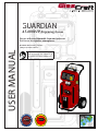
1
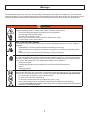
GUARDIAN
A5-6000 IP Dispensing System
For use with non-flammable foam and polyurea.
Not for use in explosive atmospheres.
USER MANUAL
Maximum fluid working pressure:
(1600 psi. (11 MPa, 110 bar)
EN
T IS P R
CHINESE
PATENT
HI
ZL 200630130159.1
T
T
M
CT ED B
Y
U.S.A.
PATENT
D546,840
S E Q UI P
T IS P R
CT ED B
Y
HI
EN
TE
O
M
TE
O
S E Q UI P
Important Safety Instructions
Read all warnings and instructions in
this manual. Save these instructions.
Table Of Contents
Section 1 Installation
Warnings ....................................................................................................................................................................2
Standard Equipment .................................................................................................................................................. 5
Specifications..............................................................................................................................................................6
Introduction ................................................................................................................................................................ 7
Equipment Assembly ..................................................................................................................................................8
Section 2 Operation
Start-up Instructions ...................................................................................................................................................13
Shut–down Instructions ..............................................................................................................................................17
Section 3 General Information
Assembly Drawings ....................................................................................................................................................21
Sub Assembly Drawings .............................................................................................................................................26
Maintenance ...............................................................................................................................................................31
Troubleshooting ..........................................................................................................................................................32
Section 4 Warranty and Reference Information
.............................................................................................................................................35
Limited Warranty Policy ...................................................................................................................37
Technical Assistance .......................................................................................................................38
For Your Reference ............................................................................................. INSIDE BACK COVER
Notes
Warnings
The following warnings are for the setup, use, grounding, maintenance, and repair of this equipment. The exclamation
point symbol alerts you to a general warning and the hazard symbol refers to procedure-specific risk. Refer back to these
warnings. Additional, product-specific warnings may be found throughout the body of this manual where applicable.
WARNING
ELECTRIC SHOCK HAZARD
Improper grounding, setup, or usage of the system can cause electric shock.
• Turn off and disconnect power cord before servicing equipment.
• Use only grounded electrical outlets.
• Use only 3-wire extension cords.
• Ensure ground prongs are intact on sprayer and extension cords.
•
Do not expose to rain. Store indoors.
TOXIC FLUID OR FUMES HAZARD
Toxic fluids or fumes can cause serious injury or death if splashed in the eyes or on skin, inhaled, or
swallowed.
•
Read MSDS’s to know the specific hazards of the fluids you are using.
• Store hazardous fluid in approved containers, and dispose of it according to applicable guidelines.
• Always wear impervious gloves when spraying or cleaning equipment.
PERSONAL PROTECTIVE EQUIPMENT
You must wear appropriate protective equipment when operating, servicing, or when in the operating
area of the equipment to help protect you from serious injury, including eye injury, inhalation of toxic
fumes, burns, and hearing loss. This equipment includes but is not limited to:
•
Protective eyewear
• Clothing and respirator as recommended by the fluid and solvent manufacturer
• Gloves
• Hearing protection
SKIN INJECTION HAZARD
High-pressure fluid from gun, hose leaks, or ruptured components will pierce skin. This may look like
just a cut, but it is a serious injury that can result in amputation. Get immediate surgical treatment.
•
Do not point gun at anyone or at any part of the body.
•
Do not put your hand over the spray tip.
•
Do not stop or deflect leaks with your hand, body, glove, or rag.
• Close material shutoff valves and shutoff or disconnect air supply when not spraying.
• Follow Pressure Relief Procedure in this manual, when you stop spraying and before cleaning,
checking, or servicing equipment.
1
Warnings
FIRE AND EXPLOSION HAZARD
WARNING
Flammable fumes, such as solvent and paint fumes, in work area can ignite or explode. To help prevent fire and explosion:
• Use equipment only in well ventilated area.
• Eliminate all ignition sources; such as pilot lights, cigarettes, portable electric lamps, and plastic
drop cloths (potential static arc).
•
Keep work area free of debris, including solvent, rags and gasoline.
•
Do not plug or unplug power cords, or turn power or light switches on or off when flammable
fumes are present.
• Ground all equipment in the work area.
• Use only grounded hoses.
• Hold gun firmly to side of grounded pail when triggering into pail.
• If there is static sparking or you feel a shock, stop operation immediately. Do not use equipment until you identify and correct the problem.
•
Keep a working fire extinguisher in the work area.
PRESSURIZED ALUMINUM PARTS HAZARD
Do not use 1,1,1-trichloroethane, methylene chloride, other halogenated hydrocarbon
solvents or fluids containing such solvents in pressurized aluminum equipment. Such
use can cause serious chemical reaction and equipment rupture, and result in death,
serious injury, and property damage.
EQUIPMENT MISUSE HAZARD
Misuse can cause death or serious injury.
•
Do not operate the unit when fatigued or under the influence of drugs or alcohol.
•
Do not exceed the maximum working pressure or temperature rating of the lowest rated system
component. See Technical Data in all equipment manuals.
• Use fluids and solvents that are compatible with equipment wetted parts. See Technical Data in
all equipment manuals. Read fluid and solvent manufacturer’s warnings. For complete information about your material, request MSDS forms from distributor or retailer.
• Check equipment daily. Repair or replace worn or damaged parts immediately with genuine
manufacturer’s replacement parts only.
•
Do not alter or modify equipment.
• Use equipment only for its intended purpose. Call your distributor for information.
•
Route hoses and cables away from traffic areas, sharp edges, moving parts, and hot surfaces.
•
Do not kink or over bend hoses or use hoses to pull equipment.
•
Keep children and animals away from work area.
• Comply with all applicable safety regulations.
MOVING PARTS HAZARD
Moving parts can pinch or amputate fingers and other body parts.
•
Keep clear of moving parts.
•
Do not operate equipment with protective guards or covers removed.
•
Pressurized equipment can start without warning. Before checking, moving, or servicing equipment, follow the Pressure Relief Procedure in this manual. Disconnect power or air supply.
BURN HAZARD
Equipment surfaces and fluid that’s heated can become very hot during operation. To avoid
severe burns, do not touch hot fluid or equipment. Wait until equipment/fluid has cooled completely.
2
Warnings
Isocyanate Hazard
To prevent exposing ISO to moisture:
Spraying materials containing isocyanates creates
potentially harmful mists, vapors, and atomized
particulates.
Read material manufacturer’s warnings and
material MSDS to know specific hazards and
precautions related to isocyanates.
Prevent inhalation of isocyanate mists, vapors, and
atomized particulates by providing sufficient ventilation in the work area. If sufficient ventilation is not
available, a supplied-air respirator is required for
everyone in the work area.
To prevent contact with isocyanates, appropriate
personal protective equipment, including chemically
impermeable gloves, boots, aprons, and goggles, is
also required for everyone in the work area.
Material Self-Ignition
Some materials may become self-igniting if applied
too thickly. Read material manufacturer’s warnings
and material MSDS.
Moisture Sensitivity of
Isocyanates
Isocyanates (ISO) are catalysts used in two component
foam and polyurea coatings. ISO will react with moisture
(such as humidity) to form small, hard, abrasive crystals,
which become suspended in the fluid. Eventually a film will
form on the surface and the ISO will begin to gel, increasing in viscosity. If used, this partially cured ISO will reduce
performance and the life of all wetted parts.
The amount of film formation and rate of crystallization varies depending on the blend of ISO,
the humidity, and the temperature.
3
•
Always use a sealed container with a desiccant dryer
in the vent, or a nitrogen atmosphere. Never store ISO
in an open container.
•
Keep the ISO lube pump reservoir filled with Graco
Throat Seal Liquid (TSL), Part 206995. The lubricant
creates a barrier between the ISO and the atmosphere.
•
Use moisture-proof hoses specifically designed for
ISO, such as those supplied with your system.
•
Never use reclaimed solvents, which may contain
moisture. Always keep solvent containers closed when
not in use.
•
Never use solvent on one side if it has been contaminated from the other side.
•
Always park pumps when you shutdown.
•
Always lubricate threaded parts with Part 217374 ISO
pump oil or grease when reassembling.
Warnings
Keep Components A and B
Separate
Changing Materials
CAUTION
To prevent cross-contamination of the equipment’s wetted parts, never interchange component A (isocyanate)
and component B (resin) partrs. The gun is shipped with
the A side on the left. The fluid manifold, fluid housing, side seal assembly, check valve cartridge, and mix
chamber are marked on the A side.
Foam Resins with 245 fa
Blowing Agents
New foam blowing agents will froth at temperatures above
90°F (33 °C) when not under pressure, especially if agitated. To reduce frothing, minimize preheating in a circulation
system.
4
•
When changing materials, flush the equipment multiple times to ensure it is thoroughly clean.
•
Always clean the fluid inlet strainers after flushing.
•
Check with your material manufacturer for chemical
compatibility.
•
Most materials use ISO on the A side, but some use
ISO on the B side.
•
Epoxies often have amines on the B (hardener) side.
Polyureas often have amines on the B (resin) side.
Section 1 - Installation: Standard Equipment
Model - A5-6000 IP
Part
Number
Description
GC1751
A5-6000 IP UNIT, 220V, 1PH, F
GCP2R2*
PROBLER P2 GUN
GC0393*
48 FT. HEATED HOSE ASSEMBLY
GC0319
GRAVITY FEED KIT
313273
USER MANUAL
206995
FLUID, TSL, 1 QT. BOTTLE
* Purchased Separately
Recommended Repair Parts
Part
Number
Description
GC1748
HEATER REPAIR KIT
Related Manuals
Part
Number
Description
313277
MATERIAL PUMPS MANUAL
5
Section 1 - Installation: Specifications
Material Ratio:
1:1 (Fixed)
Material Viscosity:
Output:
200- 2000 Centipoise (Cps) @ AMBIENT
Operating Temperatures:
32º F ( 0º C ) - 180º (82 º C )
Maximum Air Working Pressure:
Maximum Fluid Working Pressure: 100 psi (0.69 MPa, 6.9 bar)
16:1 RATIO 1600 psi (11 MPa, 110 bar)
Pumps Rated:
.042 Gallons Per Cycle
.159 Liters Per Cycle
Electrical Requirements:
50 A @ 208/240 VAC,50/60 hz, Single Phase
(cable: 6 AWG, 2 wire and ground)
Compressed Air Requirements:
Base Unit:
1.0 GAL PER MINUTE – 17 CFM @ 100 PSI.
1.5 GAL PER MINUTE – 24 CFM @ 100 PSI.
2.0 GAL PER MINUTE – 33 CFM @ 100 PSI.
NOTE: As output is increased, (achieved w/ chamber size on gun or spray tip), pressure drop will be greater. Heating capability will also drop.
Heaters:
6000 WATT HEATER
Maximum Hose Length:
200 ft (61 m)
(Each Section 50 ft x 1/4 in. I.D.)
Shipping Weight:
428 lbs. (194 kg)
Overall Dimensions:
6
Section 1 - Installation: Introduction
The information in this document is intended only to
indicate the components and their normal working
relationship typical use. Each assembly should be
directed by a GlasCraft distributor or made from the
GlasCraft Assembly instructions provided.
Before operating, maintaining or servicing any
GlasCraft system, read and understand all of the
technical and safety literature provided with GlasCraft
products. If you do not have the proper or related
manuals and safety literature for your GlasCraft system,
contact your GlasCraft distributor.
This manual provides information for the assembly, operation, maintenance and service of this GlasCraft product as
used in a typical configuration. While it lists standard specifications and procedures, some deviations may be found.
In this GlasCraft technical and safety publication, the
following advisories will be provided where appropriate:
Is information about the procedure in progress.
In order to provide our users with the most up-to-date
technology possible, we are constantly seeking to improve
products. If technological change occurs after a product is
on the market, we will implement that technology in future
production and, if practical, make it available to current
users as a retrofit, up-date or supplement. If you find some
discrepancy between your unit and the available documentation, contact your GlasCraft distributor to resolve the
difference.
Is imperative information about equipment protection.
CAUTION
Indicates a hazardous situation that can result in minor
or moderate injury.
WARNING
Careful study and continued use of this manual will provide a better understanding of the equipment and process,
resulting in more efficient operation, longer trouble-free
service and faster, easier troubleshooting.
Indicates a hazardous situation that can result in death
or serious injury.
ELECTRICAL SHOCK HAZARD
Indicates a hazardous situation that can result in
electrical shock or serious injury.
7
Section 1 - Installation: Equipment Assembly
Guardian Line Installation Guide
d. You will need to run an air line to the area where
the machine will be placed. consult the data
sheet the specific unit being installed to determine
much clean, dry air will be needed to supply the
machine. If the air line is under 25 ft. use a
minimum of 1/2 in. I.D. pipe or hose. If the air line
is longer than 25 ft., use a minimum of 3/4 in.
pipe or hose. Anything smaller than these
diameters will severly affect the machine’s
performance!
GlasCraft Systems are factory assembled. If any
questions arise concerning air or electrical
connections, please refer to illustrations located in
the forward portion of this User Manual or contact
your GlasCraft distributor.
1. Locate Guardian.
a. Locate Guardian on a level surface.
b. Do not expose Guardian to rain.
Do not use any quick disconnect fittings on
the main air line going to the machine!
CAUTION
Check your air-compressor to make sure it is
capable of supplying the maximum amount of air
that the machine requires. All GlasCraft equipment
is rated at 25 CFM (cubic foot per minute) 708
liters at 90- 100 psi (.62-0.7 MPa, 6.3-7.7 bar)
do not exceed 125 psi (0.86 MPa, 8.6 bar).
Bolt Guardian to original shipping palet before lifting.
c. Use the wheels to move Guardian to a fixed
location, or bolt to shipping pallet and move
with forklift.
d. To mount on a truck bed or trailer, bolt directly to
truck or trailer bed.
3. Move material drums to the area that the equipment will
be placed, ensuring that they are not sitting directly on
the floor. Simply place the drums on top of a palate or
similar device, so the drum bottoms will not be in
contact with any cold surfaces.
2. Advanced preparation
a. Before beginning any installation, ensure that the
applicator has the desired power supply available,
(i.e. 220V single phase / 380V three phase),
within 10 ft. of were the machine is to be placed.
If the machine needs to be further that 10 ft. from
the power supply, additional lengths of properly
sized electrical cable will be required.
4. Open all boxes that came with the machine and verify
that all items are accounted for.
Never use a smaller gauge size than supplied
by the factory!
b. Depending on the electrical setup, it may be
necessary to install an appropriate plug on the end
of the cable. GlasCraft will not supply this plug, as
we are unaware of which style will be needed.
c. Consult the data sheet for the specific unit being
installed to determine the proper breaker size
needed.
8
Section 1 - Installation: Equipment Assembly
4. Install the gravity feed kit GC0319 as shown.
GC0085
GC1979
GC2161
GC2214
GC0005
GC2208
3/4 in. ID HOSE
9
Section 1 - Installation: Equipment Assembly
Main power from power source should be disconnected or turned off to console before making hose
connections.
Trigger Air
5. Connect the hose assembly to the unit.
The swivel fittings on the Hose assembly
are sized differently and will attach only
one way.
6. Connect the “yellow” heat plug to the outlet
on the front of the unit.
7. Connect trigger air line to the air regulator
at the system air manifold.
8. Connect the thermocouple plug to the
outlet on the “back” of the unit.
10
Section 1 - Installation: Equipment Assembly
GC0705 Extension hose
Machine End
9. Continue adding extra hose lengths if necessary.
The GlasCraft System is factory assembled. If
any questions arise concerning air or electrical
connections, please refer to illustrations located in
the forward portion of this User Manual or contact
your GlasCraft distributor.
Machine End
Required Tools:
Opened - end wrenches - 5/8in., 3/4 in., 13/16 in.
a. Lay hoses out straight.
b. Couple hoses together with supplied union fittings
and tighten finger-tight.
c. • Hold crimp fitting hex (3/4 in.), and union fitting
together, allowing the hose to hold it’s natural line.
• Using the appropriate wrench (A-side 3/4 in. /
B-side 13/16 in.) tighten swivel fitting to union, not
allowing crimp fitting or union to turn. Repeat on
opposite side of union.
This practice is required on all connection
points.
1) Hose @ machine
2) Hose @ gun
3) Adding additional hose sections
d. Attach the yellow power plugs.
GC0393 Standard hose
Gun End
e. Attach the thermocouple
extension cable. p/n GC0885.
11
Section 1 - Installation: Equipment Assembly
10. Connect the hose assembly to the spray gun as
shown.
11. All connections should now be tight!
When Main Power to system console is on, the white
and black wires in the console are always live!
Disconnect or turn off Main Power source before
opening console to make any repairs or before making
any electrical repair of any type to the system.
If you do not understand the electrical hook-up
described above, consult your local GlasCraft distributor
OR a qualified electrician.
Electrical connections must be checked on a
periodic basis.
12. Connect the white and black wires of the Power cord to a single phase of 208/240 VAC, 50/60 HZ.
The green wire should be connected to GROUND
WHITE
POWER CORD
208 / 240 VAC
50 / 60 HZ.
SINGLE PHASE
50 AMP MIN.
25
BLACK
GREEN
GROUND
12
Section 2 - Operation: Start-Up Instructions
Never leave machine unattended while system power
is on or system is running.
System running is defined as: preheat cycle of the hose
heat, primary heaters, or any pump operation.
Machine operators must be familiar with the
component functions and operation of the machine.
Filling The System
1. Adjust air regulator to 20 psi to fill system. Air motor will cycle slowly to fill pumps, heaters and
hoses and stop.
Pre-Operation Check List
A. Check that all fittings are securely tight.
B. Check electrical hook-up (qualified electrician
recommended).
C. Main power switch on control box should be 2. Remove ISO & POLY side blocks from gun.
switched to OFF position.
D. Air regulator turned (counter clock-wise) to OFF position.
E. Hose control and primary heater control to OFF position.
Do not place any part of the body in the path of the
material spray.
Do not point the gun at or near other personnel.
Do not look into the mixing chamber orifice at any time.
Because of the hazardous materials used in this
equipment, it is recommended that the operator use
an air mask, goggles, protective clothing, and other
safety equipment as prescribed by current regulations,
recommendations of the chemical suppliers, and the
laws in the area where the equipment is being used.
PROBLER P2
MAKE SURE VALVES ARE OFF
Initial Start-Up Procedure
With all material and air lines connected and power
cable attached, the system is now ready for start-up.
13
Section 2 - Operation: Start-Up Instructions
3. Place separate clean containers under each indi vidual side block. Slowly open material valves
(black arrow forward) on each side block to allow
trapped air to escape the hose and material to flow
into the containers until all air is purged from the
material system.
6. Clean and lubricate Side Blocks and Seals thoroughly
and re-assemble on Gun. Make certain that the side
block screws are tightened securely.
7. Refer to material manufacturers operating instructions
for proper preparation of material, i.e, mixers, etc.
8. Leave Air Regulator at 20 PSI
9. Turn main power Switch to ON position.
Remember to dispense one to two gallons of
material to clear the system of grease and
plasticizer that was used during factory testing.
4. Close manual material valves. Material pressure
gauges should now register approximately equal
pressure. If one side registers considerably more
pressure than the other side, go to the high pres-
sure side and bleed off some pressure by slightly
opening the manual material valve on the side
block over the container. Bleed pressure until both
sides are approximately the same pressure.
10. Turn on Hose Control:
a. Push in the green power button.
b. Press up or down arrow buttons on the controller
until desired temperature setting is achieved.
5. Dispose of waste material properly and in accordance with chemical suppliers instructions and
local, state and federal regulations.
Before re-assembling Side Blocks, lubrication can be
applied by dabbing a white lithium grease into
holes inside of Gun Front Housing and wiping
grease over SideBlock Seals. Grease will purge
itself when air valve is turned on at Gun and Gun
is triggered.
14
Section 2 - Operation: Start-Up Instructions
11. Turn on the ISO & POLY Heater control:
12. Adjust Main Air Regulator to material suppliers
a. Push in green power button.
b. Press up or down arrow buttons on the
controller until desired temperature setting is
achieved.
specifications.
13. Turn Purge Air and Material Valves ON at Gun.
Straighten hose out flat, to avoid uneven heating and
damage to internal wiring of the Hose Assembly.
Allow enough time for hose to warm up (approximately
15- 20 minutes). Remember that the heated hose
does not have a delta rating. The heated hose’s function is to maintain the heat generated by the primary
heaters during system operation, and preheat material
during initial start-up. The hose should be set to
maintain a temperature close to the set point of the
heaters.
Due to the expansion of urethanes when heated, it is
imperative that on cold start-up of the system that the
heaters be turned on and allowed to reach operating
temperatures before the Main Pump Air Regulator is
adjusted to the desired spray pressure. If you do not
allow the heaters to reach operating temperature before
adjusting air pressure, the material pressure will exceed
the set point of the over pressure switches causing the
system to shut down.
ON
OFF
14. Relieve any excess pressure by triggering the gun.
The Emergency Stop Switch is located on the bottom
right side of the control Panel, when depressed, it will
shut down the power and activate the Air Dump Valve.
To reset, turn handle on push button.
15. The system is now ready for operation.
15
Section 2 - Operation: Start-Up Instructions
Change Temperature Controller Display
Units (Fhrenheit or Celsius)
2. Scroll through the Setup Menu by pressing the
button until the display reads “C-F” (press
3 times).
220 V units are factory set to display temperature readings
in degrees Fahrenheit. 380 V units are factory set to display
tempertature readings in degrees Celsius.
3. Press and hold the
The temperature display units can be changed with the following procedure:
4. Continue to hold the
1.
On the Watlow SD31 controller, press and hold the
and
buttons simultaneously for 3
seconds until the display reads “SET”. This is the
Setup Menu.
unit setting of “C” of “F”.
.
button
button to display the current
button and press the
button to switch to the desired unit setting, “C” or “F”.
5. Release the
button.
6. Press the infinity button
to exit the Setup Menu; the
temperature display unit is now changed.
7. Complete steps 1-6 for all three controllers (ISO, POLY,
HOSE).
Do not change any other settings in the Setup Menu.
The settings have been factory programmed for optimal performance.
16
Section 2 - Operation: Shut-Down Instructions
Daily Shut-Down Procedure
5. Reduce main air regulator pressure to zero.
1. Turn off hose and heater controllers.
2. Turn off main power switch.
6. Visually inspect the entire system for leaks.
7. Turn off main air supply and main power.
3. Flip retract switch to the “retract position” and trigger
the gun until pumps are in the down position.
4. Perform gun maintenance. (See gun manual)
17
Section 2 - Operation: Shut-Down Instructions
8. Coil heated hoses with a minimum four foot diameter
to avoid kinking and subsequent damage to the
internal electrical wiring.
9. Check and lube top of the fluid section.
2. Use a suitable solvent to flush the fluid circuits. To
determine the compatibility of solvents with material
being used. Always check with material supplier.
3. Increase transfer pump pressure until fluid
movement occurs.
Wipe off residual material
and add a tablespoon
of throat seal liquid (TSL).
If fluid movement does NOT occur @ 100 psi
of air on transfer pumps, increase main pump
pressure until the main proportioner SLOWLY
starts cycling.
4. Once primary material is flushed from the system,
reduce the main air pressure to zero or flip the
retract switch to the “retract position” and trigger
the gun until the pumps are in the down position.
5. If the solvent used to flush the system also contains
placticizer, ensure that all primary material is flushed
from the system and close the ball valves @ the gun.
Do not bleed fluid pressure from the system.
6. Leave the pumps in the full down stroke position with
approximately 200-500 psi. on the fluid gauges.
7. If plasticizer is required to chase out solvent, cycle
Extended Shut-Down Procedure
main pumps until the system is full of plasticizer, then
close valves and leave the pumps in the full down
stroke position with 200-500 psi.
The following procedure is for long extended shut-down
periods.
Power should be disconnected and all air regulators
turned down to zero.
1. Remove side blocks from the gun and relieve pressure from the system.
PROBLER P2
18
Section 2 - Operation: Shut-Down Instructions
8. Turn off main air supply and disconnect air line from
the system.
9. Generously coat the exposed transfer pump shafts
2. Adjust main air regulator to 20 psi.
3. Adjust transfer pump regulators to approximately 40 psi.
with lithium grease.
10. Coil the heated hoses with a minimum four foot
diameter to avoid kinking and subsequent damage to
the internal electrical wiring.
11. For gun shut down, follow the procedure from the
gun manual.
12. The length of time a system is shut down, and the
climate conditions it’s stored in will determine how
often the system should be purged and refilled.
Usually every 2 - 4 weeks the following procedure
should be followed.
4. Remove the side blocks from the gun.
Purge and Refill Procedure
1. Connect the main air line to the system.
PROBLER P2
19
Section 2 - Operation: Shut-Down Instructions
5. Open both side blocks simultaneously into separate
containers and dispense approximately 1-1/2 - 2
gallons of material from each side or until all
plasticizer is purged from the system. Stop the
pumps in the down position.
Before performing any repairs on any part of the system,
PLACE ALL CONTROLS ON THE MACHINE AND THE
MAIN POWER SOURCE IN THE OFF
POSITION AND DISCONNECT THE ELECTRICAL
POWER CABLE FROM THE MAIN POWER SOURCE!
6. Close both side blocks simultaneously and wipe off
residue from the side block seals. Regrease and
attach both blocks to the gun.
7. Mix and properly dispose of purge material.
Before performing any repairs on the system,
ALL AIR and FLUID PRESSURES SHOULD BE
RELIEVED TO ZERO (BLEED-OFF)!
To relieve Air and Fluid pressures:
System Console:
1. Turn OFF valves that supply material to the Pumps.
2. Turn OFF Main Air Regulator on Air Motor.
Gun:
1. Open both Side Block Material Valves.
2. Turn ON Air Switch.
3. Point Gun into a clean, suitable container and
trigger Gun until material flow stops.
4. Fluid pressure gauges must read zero (0), if not,
trigger Gun until the fluid pressure gauges do read zero (0) pressure.
5. Turn OFF Side Block Material Valves.
6. Trigger Gun several more times to purge any
material remaining in Gun. Turn OFF air Switch.
7. Unless system is to be returned to service at once,
follow DAILY SHUT-DOWN PROCEDURE
20
Section 3 - General Information: Assembly Drawings
GC1751 Unit Assembly
17
20
5, 38
47
13
13
2
48
8
48
25
11
10, 36
23
16
5, 38
5, 38
26
21
39, 40
included with
control panel
35, 37, 41
1, 36
Detail A
27
supplied with cart assembly
See Detail A
Some parts have been removed for clairty.
21
19
Section 3 - General Information: Assembly Drawings
GC1751 Unit Assembly
7
42
7
24
42
15
24
4, 38
4, 38
3, 38
18
18
14
4, 38
24
4, 38
3, 38
Red tubing
24
46
44
9
47
45
Blue tubing
Receptacle A
Receptacle B
45
To Receptacle B
46
To
Receptacle A
49
22
22
22
Section 3 - General Information: Assembly Drawings
GC1751 Parts List
Ref.
Part
1*
Qty.
45
GC2363
LABEL, ISO
2
RIVET, BLIND, 0.188 dia.x 0.425 STL
5
46
GC2364
LABEL, POLY
2
1
47
GC2365
LABEL, HOSE
2
48
GC2368
LABEL, MAIN
2
49
GC0805
SWITCH, PRESSURE, HIGH
2
Description
2
15G280
LABEL, WARNING
3
112925
SCREW, CAP, BTNHD
4
GC0433
SCREW, BHDC, SS, 0.250-20X 0.625
4
12
10
5
GC0434
SCREW, BHDC, SS, 0.250-20X 0.875
7
GC0578
ELBOW, JIC, 3/8 NPTM X 3/4 UNF S
2.
8
GC0797
LABEL, LIVE WIRE
1
9
GC0811
CONNECTOR
1
SCREW, 1 IN, #10, SELF TAP
4
GC1071
SWITCH, POWER, ON/OFF
1
CABLE, POWER, 11 FT
1
13
GC1181
GAUGE, PRESSURE, 3000PSI,
BACK MT
2
14
GC1714
HEATER, ASSY, HEATER, DUAL,
ROD, ISO
1
15
GC1716
HEATER, HEATER, DUAL, ROD,
POLY, 1500
1
16
GC1718
PLATE, BOTTOM
1
10*
11
12*
17
CART, ASSY., 1 P; SEE PAGE 26
1
18
GC1725
COVER, HEATER
2
19
GC1726
COVER, SHELL
1
20
GC1730
RING, PANEL, CONTROL
1
21
GC1736
PUMP, ASSY.
1
22
GC1744
HOSE, ASSY
2
NUT, RIVET
4
24
GC1746
WASHER, FIBER
4
25
GC1756
LABEL, DECAL, GUARDIAN, A56000 IP
1
CONTROL, PANEL; SEE PAGE 28
1
1
23*
26
27
GC1767
CONTROL, A5/A6-6000IP, 220V, 1PH
35
GC2052
WASHER, FLAT
2
WASHER, FLAT
9
36*
37
GC2107
WASHER, LOCK, SPRING
2
38
GC2109
WASHER, LOCK, SPRING
26
39
GC2112
WASHER, LOCK, SPRING
2
40
GC2175
SCREW
2
41
GC2192
SCREW
2
42
GC2203
FITTING, CONNECTOR
2
HOSE, TUBNG, P.E., 0.500OD
NATURAL; 1.4 FT.
1
44*
* Source locally.
Not Shown.
Replacement danger and warning labels, tags, and cards are available at no cost.
23
Section 3 - General Information: Assembly Drawings
GC1751 Generic System Schematic
24
Section 3 - General Information: Assembly Drawings
GC1751 System Schematic 220V Single Phase
25
Section 3 - General Information: Sub Assembly Drawings
Cart Assembly IP
124
144
117
142
121
125
141
120
106
106
101
141
141
106
157
102
109
158
137
154, 155, 156
118
153
151, 152, 140, 136
118
105
135
128
123
149
150
134, 142
145
Some Parts Removed For Clarity
Attach air line
for gun here
108
130,148
130,148
113
104
113
113
130,148
130,148
132
138
140
147
133
132
See Detail
134,142,144
104
111
103
129
108
Some Parts Removed For Clarity
112
146
136,140,143
107
Detail A
26
Section 3 - General Information: Sub Assembly Drawings
Cart Assembly IP
Ref.
Part
101
GC0012
ELBOW
102
GC0025
103
GC0217
Ref.
Part
2
143
GC2119
SCREW
1
PLUG, PIPE
1
144
GC2180
SCREW
6
FITTING, ADAPTER, NPSM,1/4
X 1/4
1
145
GC2185
SCREW
4
SCREW
4
Description
Qty.
104
GC0286
HOSE, ASSY
1
105
GC0409
SCREW, BHDC, SS, .312-18X
.750
2
106
112925
SCREW, CAP, BTNHD
107
GC0437
SCREW, SET, SOC., 7/16-20 X
3/8
1
RETAINER, PLUG, VENT,
RETAINER
7
108*
10
146*
Description
Qty.
147
GC2192
SCREW
4
148
GC2372
GRIP, CORD
4
NUT, CONDUIT
1
149*
150*
CONNECTOR
1
151
GC0796
SOLVENT, RECEPTACLE
1
152
GC2092
NUT, HEX, STD, 8-32
2
153
GC1740
BRACKET, RECEPTACLE,
HOSE
1
GC1612
PLATE, COUPLING
1
109
GC0790
HOSE, ASSY
2
111
GC0999
TRANSFORMER, BOX,
CONTROL
1
154
155
GC1621
LIGHT, PILOT, WHITE
1
112
GC1040
CONNECTOR
1
156
GC1625
LIGHT, LED, WHITE, 240V
1
113
15W209
JACK, PANEL, CIRCULAR
3
157
GC2207
FITTING, #6 JIC x 1/4 NPT
1
117
GC1719
HANGER, PANEL, CONTROL
2
158
GC0242
FITTING, 5/8-18 SAE X 1/4 NPT
1
118
GC1723
COVER, HEATER
2
120
GC1738
FITTING, BULKHEAD, 1/4 NPT X
1/4 NPT
2
121
GC1739
NUT, BULKHEAD, 3/4-16
2
Part
123
GC1743
WHEEL
2
GC0020
FITTING
3
124
GC1749
MANIFOLD, ASSY, AIR
1
GC0222
REGULATOR, AIR
2
125
GC1754
MANIFOLD, ASSY, FLUID
1
GC0240
GAUGE, AIR,
2
GAUGE, AIR
1
FITTING, ELBOW
1
* Source locally.
Description
Qty.
128
GC1810
COUNTER, WEIGHT
4
GC0241
129
GC1811
EXTENSION, STANDOFF
4
*
130
GC1999
NUT, CONDUIT, ELEC., 1/2
4
GC0755
VALVE, BALL
1
GC1720
BRACKET, L
1
GC1732
MANIFOLD, AIR
1
132*
GROMMET, RUBBER, 3/8 THRU,
1/4PT
2
133*
GROMMET, RUBBER, 1-1/2
THRU, 1/4PT
1
134
GC2044
WASHER, FLAT
8
135
GC2045
WASHER, FLAT, FENDER
2
136
GC2048
WASHER, FLAT, STD
1
WASHER, FLAT, STD
4
137*
138
GC2052
WASHER, FLAT, STD
4
140
GC2107
WASHER, LOCK, SPRING
5
141
GC2109
WASHER, LOCK, SPRING
10
142
GC2110
WASHER, LOCK, SPRING
10
GC0000
CAP, OILER
2
GC0001
GASKET, CAP, OILER
4
GC1994
FITTING, ELBOW
1
GC2016
FITTING, PIPE, TEE
1
GC2110
WASHER,LOCK, SPRING
2
GC2167
FITTING, PIPE, NIPPLE, HEX
2
GC2169
FITTING, PIPE, NIPPLE, HEX
2
GC2170
FITTING, PIPE, NIPPLE, HEX
1
GC2179
SCREW
2
GC1772
LABEL, GLASCRAFT, MANIFOLD,
GRDN
1
27
Section 3 - General Information: Sub Assembly Drawings
Control Panel Assembly
228
225
221
218
223
220
204
201
227
226
217
220
224
222
214
215
236
228
227
220
219
209
205
210
213
203
202
Ref.
Part
Description
201
GC0584
202
203
204
212
208
Qty.
Ref.
Part
Description
COUNTER, LCD
1
221
GC1614
LENS, ILLUMINATED, "R"
GC0599
FUSE, 1/2 AMP
3
222
GC1616
LENS, ILLUMINATED, "I/O"
2
GC0601
FUSE, 2AMP
1
223
GC1617
LENS, YELLOW
3
15W684
MODULE, HEATER CONTROL,
GUARDIAN
2
224
GC1619
LENS, GREEN
2
225
GC1622
LED, YELLOW, 24V
3
226
GC1624
LED, GREEN, 24V
2
227
GC1626
BLOCK, CONTACT, NORMALLY
OPEN
5
228
GC1627
BLOCK, CONTACT, NORMALLY
CLOSE
5
230
GC1779
CABLE, PLUG, ELEC., FEMALE
2
231
GC1780
CABLE, PLUG, ELEC.,FEMALE
1
232
GC1782
CABLE,PLUG, ELECTRICAL,
MALE, 6, SM
2
233
GC1783
CABLE, PLUG, ELECTRICAL,
MALE
1
236
15W687
MODULE, HOSE CONTROL,
GUARDIAN
1
205*
RAIL, DIN; 0.875
208
GC0859
FUSE, FUSEHOLDER, DIN RAIL
4
209
GC0956
LABEL, EMERGENCY STOP
1
210
GC0972
BLOCK, JUMPER, TERMINAL
2
212
GC1161
RELAY, 3 POLE 10AMP
4
213
GC1164
SOCKET, RELAY, 3 POLE, 10AMP
4
214
GC1172
TERMINAL, 2IN/2OUT
6
215
GC1173
COVER, END, TERMINAL, 2 in.,2 OUT
3
217
GC1608
BUTTON, LATCHED
2
218
GC1609
BUTTON, MOMENTARY
3
219
GC1611
BUTTON, EMERGENCY STOP
1
220
GC1612
PLATE, COUPLING
6
* Source locally.
28
Qty.
3
Section 3 - General Information: Sub Assembly Drawings
GC1767 Electrical Assembly
303
312
306, 307, 308
303
310, 311
304
313
301
302
305
309
Ref.
Part
Description
301
GC0601
FUSE, 2 AMP
2
302
GC0602
FUSE, 3AMP
2
303*
Qty.
RAIL, DIN
304
GC0851
CIRCUIT BRKR, CIRCUIT, DIN RAIL, 20/2
2
305
GC0859
FUSE, FUSEHOLDER, DIN RAIL
4
306
GC0863
RELAY, FINDER, DIN RAIL,16A
1
307
GC0864
RELAY, SOCKET, DIN RAIL W/OUTCLI
1
308
GC0866
CLIP, RELAY, SOCKET, DIN RAIL
1
309
GC1015
RELAY, SOLID STATE, 50A
3
310
GC1055
SWITCH, SWITCH, ON/OFF, 3 POLES
1
311
GC1060
COVER, BLOCK, SWITCH, ON/OFF, 3POL
1
312
GC1262
RELAY, CONTCTR, MECHANICAL, 4-POLE
1
313
GC1651
CLAMP, END, TERMINAL, UNIVERSAL
2
* Source locally.
29
313
Section 3 - General Information: Sub Assembly Drawings
GC1714, GC1715, GC1716, GC1717 Heat Exchanger Assembly
417,
418
409
405
402
403
401
402
404, 416
410
411
408
417, 418
Ref.
Part
401
GC0025
Description
Qty.
PLUG, PIPE, SOC, 1/4, ZP
1
402
GC1748
KIT, O-RING (kit includes 4)
4
403
GC0482
CONNECTOR, CONNECTOR
1
404
GC0554
SCREW, BHDC, SS, .112-40X .188
4
GC0559
THERMOMETER, THERMOCOUPLE, VELOCITY, HIGH
1
ELEMENT, HEATER; SEE TABLE
2
405
406
407
GC0962
SWITCH, OVERTEMP, OPENED
2
408
GC1226
SPRING, COMPRESSION, .86 OD,17"
2
409
GC1711
CAP, FRONT, HEATER, DUAL, A5-6000
1
410
GC1712
CAP, REAR, HEATER, DUAL, A5-6000
1
411
GC1713
HOUSING, BODY, EXTRUDED, HEATER
1
412
GC1773
CABLE, PLUG, ELEC., FEMALE, 2,LG
1
413
GC1774
CABLE, PLUG, ELEC., MALE, 2,LG
1
414
GC1778
CABLE, PLUG, ELEC., FEMALE, 2, SM
1
415
GC1781
CABLE, PLUG, ELEC., MALE, 2, SM
1
416
GC2105
WASHER, LOCK, SPRING, #4
4
417
GC2109
WASHER, LOCK, SPRING, 1/4
12
418
GC2151
SCREW, SHDC, SS, .250-20X1.750
12
Not shown.
30
406
ISO
406
WATTS
Qty.
GC1714
GC0891
1500
1
GC1715
GC0893
750
1
406
WATTS
Qty.
GC1716
GC0891
1500
1
GC1717
GC0893
750
1
MODEL
POLY
MODEL
Section 3 - General Information: Maintenance
Daily Routine Maintenance
1. Visually inspect the system for leaks.
2. Check desiccant dryer to ensure proper functioning.
Replace dryer beads as necessary.
3. Check and lube top of the fluid section.
Wipe off residual material
and add a tablespoon
of throat seal liquid (TSL).
Weekly Maintenance
1. Place a small amount of grease on the air motor
shaft.
2. See related manuals.
31
Section 3 - General Information: Troubleshooting
If a high pressure situation develops, the sensor will detect
this and immediately engage the hold-in circuit.
Do not place any part of the body in the path of the
material spray.
Do not point the gun at or near other personnel.
Do not look into the Mixing Chamber orifice at any
time.
Because of the hazardous materials used in this
equipment, it is recommended that the operator
use an air mask, goggles, protective clothing, and
other safety equipment as prescribed by current
regulations, recommendations of the chemical suppliers, and the laws in the area where the equip
ment is being used.
This will disengage power to the air motor and will also
turn the heaters off.
On the control box panel, there are three yellow lighted push
buttons marked over pressure. One of these push buttons
will be illuminated after the monitoring sensor engages, indicating where the problem is located
(ISO, Poly, or Hose).
The system will dispense liquid at high pressure
when Gun Trigger is activated. Read and note
WARNINGS contained in this User Manual and
the Probler P2 Gun User Manual, GC-1386.
The Polyol will expand in the Hose if any normal
operating pressures are bled off whenever the material is above approximately 75 degrees F. Hot Polyol
hoses should never be bled, by any method, to zero
pressure for two reasons.
1. The seals in the Gun rely on high pressure to make
their seal. The high pressure cannot be maintained if
the pumps are attempting to apply this pressure
through a hose full of expanded froth; therefore, the
Gun seal may leak.
2. Re-starting immediately after hot Polyol has expanded in the system may result in spraying substantial amounts of “bad” foam. This will continue until the expanded Polyol in the primary Heater and the
Hose has been completely purged.
In the over pressure situation, the system will remain shutdown until it is manually reset.
At this point, it is necessary to determine if the problem is an
over pressure situation.
When the sensor engages, the system will be frozen, giving you the pressure readings at the time the problem was
detected.
Inspect the fluid pressure gauges, in an over pressure situation, one of the fluid pressure gauges will be significantly
higher than the other gauge.
Over Pressure System Protection
The system incorporates monitors for high
pressure monitoring. These monitoring devices will
prevent the system from continued operation if
high pressure situations develop.
There are pressure sensors located on each proportioning pump. The high pressure sensor is located at
the outbound of the fluid section.
When main power to unit is on, the console will have wires
that are live. Disconnect or turn off main power source before opening console to make any repairs.
Before performing any repairs on the system,
ALL AIR and FLUID PRESSURES SHOULD BE RELIEVED
TO ZERO (BLEED-OFF)!
The high pressure monitoring sensor will engage if
fluid pressure increases above 2000 psi.
32
Section 3 - General Information: Troubleshooting
Over Pressure Problem Correction
• WHAT GOOD MATERIAL LOOKS LIKE.
• HOW THE EQUIPMENT NORMALLY OPERATES.
1. Determine if the problem is high pressure related.
• WHAT PATH THE MATERIALS FOLLOW THROUGH THE EQUIPMENT.
2. Relieve system material pressure.
• KNOWLEDGE OF THESE TROUBLESHOOTING PROCEDURES.
3. Turn off main power.
Always start with step one, never skip any portion of
these procedures. The material pressure gauges are to
be used for troubleshooting purposes only. The
pressures registered on one gauge will not necessarily
match the other. This difference can be caused by
variance in materials, temperatures, viscosities, etc.
4. Fix the problem area:
a. Potential high pressure causes:
-Restriction
-Overheating material in static position
-ISO filter at gun
5. Re-start system for operation
1. Identify the missing material.
2. Check the material pressure gauge on the
Once the power has been turned off and problem
solved, and the main power is turned on again, the
over pressure lighted buttons will automatically be
reset.
missing material side.
a. If the missing material gauge reads HIGHER than
normal, there is a RESTRICTION problem
between the gauge and the Mixing Chamber tip
in the Gun.
If you do not understand the electrical hook-up de
scribed above, consult your local GlasCraft distributor
OR a qualified electrician.
b. If the missing material gauge reads LOWER than
normal, there is a STARVATION problem between
the gauge and the material supply system.
It is recommended that a qualified, licensed electrician
should install power to the supply disconnect.
Problems may be cyclic in that they will appear first on
only one stroke of the Proportioning Pump. Check the
pressure gauges during one of these bursts of missing
materials and always stop spraying while you are
getting a burst of good material.
You should always follow all local or national electrical
codes.
Disconnect power source BEFORE attempting any repairs or opening the Control Boxes. Access to internal
parts is limited to qualified personnel ONLY!
Place Main Power Switch in OFF position BEFORE disconnecting power cables. This equipment is not
approved for use in hazardous locations as set forth in
the National Electrical Code Article 500 and Sub-Part “S”
of the OSHA Standards.
3. Concern yourself only with the material pressure
on the missing material side. In troubleshooting a
STARVATION problem where the pressure gauge
on the missing material side is LOWER than normal,
start at the point farthest from the unit and work
forward. Check the obvious and easy things first.
Material Or Mechanical Problem
Troubleshooting Procedure
By following this procedure, you should be able to
locate and cure problems easily. Remember, however,
that a successful operator must know:
33
Section 3 - General Information: Troubleshooting
A. MATERIAL DRUMS
1. Material in drums?
2. Material temperature?
a. If the material is to cold, especially at the
bottom of the drum, it will raise the viscosity of
the material and stall Transfer Pumps.
A. GUN
1. Side Block Material Valve turned on?
2. Bore hole of Mixing Chamber clean?
3. Filter Strainer Screen clean?
4. Side hole in Mixing Chamber clean?
B. MATERIAL TEMPERATURE
B. OPTIONAL TRANSFER PUMP(S)
1. Too high a temperature on resin side can cause
1. Is it operating?
a blowing agent to pre-expand in either the
2. Is air turned on to Transfer Pump?
Hose or the Primary Heater.
3. Regulated pressure where it should be?
4. Severe contamination of pump shaft on isocyaC. HOSES
nate side. This indicates that the pump shaft is not
1. Make sure that the Hoses are not plugged.
being lubricated.
5. Check Filter of Transfer Pump.
Troubleshooting a poor spray pattern
6. Before diagnosing a faulty Transfer Pump, be sure
and check all items just listed under Transfer Pump. To troubleshoot a poor spray pattern, you must
understand the factors that affect the spray pattern.
C. FILTER ASSEMBLY
1. Check fluid filter at inlet to Proportioning Pumps
if applicable.
A. TEMPERATURE
1. Too warm a material temperature will cause a
D. PROPORTIONING PUMPS
separation (fingering) in the pattern.
1. Determine whether the burst appears on the
2. Too cold a material temperature will cause a
Pump’s up or down stroke.
stream effect.
a. If burst appears on UP stroke, check UPPER Ball Seat and Cups.
b. If burst appears on DOWN stroke, check
B. PRESSURE
LOWER Ball Seat
1. Too high a pressure will cause excessive
Follow the procedures in the order given. Remember
that repairs should be made as soon as possible.
Don’t leave the unit open to air any longer than
necessary, as this will lead to further problems, such
as moisture entering the system and causing the
isocyanate to crystallize.
overspray and/or separation (fingering).
2. Too low a pressure will cause a stream effect.
C. CONTAMINATION IN THE MIXING CHAMBER
1. A foreign object in the Mixing Chamber will
cause a poor pattern.
Correct problem(s) immediately!
After the unit has been exposed to the atmosphere, it
should be run long enough to displace the material that
was in the unit when it was opened up.
NEVER inspect filter assemblies at time of shut-down!
4. In troubleshooting, a restriction problem where the
material pressure gauge on the missing material
side is higher than normal, start at the point farthest
from the unit and work backward. Check obvious
and easy things first.
Before performing any repairs on the Gun, ALL AIR and
FLUID PRESSURES SHOULD BE RELIEVED TO
ZERO (BLEED-OFF)!
34
Section 4 - Safety Information: Notes
35
Section 4 - Safety Information: Notes
36
Section 4 - Safety Information: Limited Warranty Policy
Graco Standard Warranty
Graco warrants all equipment referenced in this document which is manufactured by Graco and bearing its name to be free from defects
in material and workmanship on the date of sale to the original purchaser for use. With the exception of any special, extended, or limited
waranty published by Graco, Graco will, for a period of twelve months from the date of sale, repair or replace any part of the equipment
determined by Graco to be defective. This warranty applies only when the equipment is installed, operated and maintained in accordance
with Graco’s written recommendations.
This warranty does not cover, and Graco shall not be liable for general wear and tear, or any malfunction, damage or wear caused by
faulty installation, misapplication, abrasion, corrosion, inadequate or improper maintenance, negligence, accident, tampering, or substitution of non-Graco component parts. Nor shall Graco be liable for malfunction, damage or wear caused by the incompatibility of Graco
equipment with structures, accessories, equipment or materials not supplied by Graco, or the improper design, manufacture, installation,
operation or maintenance of structures, accessories, equipment or materials not supplied by Graco.
This warranty is conditioned upon the prepaid return of the equipment claimed to be defective to an authorized Graco distributor for verification of the claimed defect. If the claimed defect is verified, Graco will repair or replace free of charge any defective parts. The equipment
will be returned to the original purchaser transportation prepaid. If inspection of the equipment does not disclose any defect in material or
workmanship, repairs will be made at a reasonable charge, which charges may include the costs of parts, labor, and transportation.
THIS WARRANTY IS EXCLUSIVE, AND IS IN LIEU OF ANY OTHER WARRANTIES, EXPRESS OR IMPLIED, INCLUDING BUT NOT
LIMITED TO WARRANTY OF MERCHANTABILITY OR WARRANTY OF FITNESS FOR A PARTICULAR PURPOSE.
Graco’s sole obligation and buyer’s sole remedy for any breach of warranty shall be as set forth above. The buyer agrees that no other
remedy (including, but not limited to, incidental or consequential damages for lost profits, lost sales, injury to person or property, or any
other incidental or consequential loss) shall be available. Any action for breach of warranty must be brought within two (2) years of the
date of sale.
GRACO MAKES NO WARRANTY, AND DISCLAIMS ALL IMPLIED WARRANTIES OF MERCHANTABILITY AND FITNESS FOR A PARTICULAR PURPOSE, IN CONNECTION WITH ACCESSORIES, EQUIPMENT, MATERIALS OR COMPONENTS SOLD BUT NOT MANUFACTURED BY GRACO. These items sold, but not manufactured by Graco (such as electric motors, switches, hose, etc.), are subject
to the warranty, if any, of their manufacturer. Graco will provide purchaser with reasonable assistance in making any claim for breach of
these warranties.
In no event will Graco be liable for indirect, incidental, special or consequential damages resulting from Graco supplying equipment hereunder, or the furnishing, performance, or use of any products or other goods sold hereto, whether due to a breach of contract, breach of
warranty, the negligence of Graco, or otherwise.
FOR GRACO CANADA CUSTOMERS
The Parties acknowledge that they have required that the present document, as well as all documents, notices and legal proceedings
entered into, given or instituted pursuant hereto or relating directly or indirectly hereto, be drawn up in English. Les parties reconnaissent
avoir convenu que la rédaction du présente document sera en Anglais, ainsi que tous documents, avis et procédures judiciaires exécutés,
donnés ou intentés, à la suite de ou en rapport, directement ou indirectement, avec les procédures concernées.
Graco Information
TO PLACE AN ORDER, contact your Graco distributor or call to identify the nearest distributor.
Phone: 612-623-6921 or Toll Free: 1-800-328-0211 Fax: 612-378-3505
PARA EFETUAR ENCOMENDAS OU PARA ASSISTÊNCIA TÉCNICA, contate o seu distribuidor da Graco.
POUR PLACER UNE COMMANDE OU DEMANDER DU SERVICE, contactez votre distributeur Graco.
PARA REMITIR UN PEDIDO O SOLICITAR SERVICIO, póngase en contacto con el distribuidor de Graco.
37
Section 4 - Safety Information: Technical Assistance............
Thank You for selecting GlasCraft spray equipment
Should you have any questions or need technical assistance, contact your factory authorized
GlasCraft distributor.
Distributor: _________________________
Phone: ____________________________
Sec. 4:4
Contact: ___________________________
phone 1.bmp
For any issues your distributor cannot address, the GlasCraft technical service department is
always available to assist you with the operation of your spray equipment. To help our technical
representatives expedite your call and better address your questions, please have the following
information ready and available when you phone GlasCraft.
* If your questions are not urgent, You can e-mail all correspondence to [email protected]
For Air Powered Systems:
Model: _____________________________
Serial number: _______________________
Air compressor size: __________________
CFM generated: _____________________
Type of spray gun: ____________________
Serial number: _______________________
Pressure at the system:
Hydraulic ________ Pneumatic _________
Is your equipment: Dynamic fluid pressure:
Single phase: _______ Three phase ______
ISO __________ POLY ___________
What is the inbound voltage
to your equipment: ____________________
Spray gun chamber size: ______________
Material being sprayed: _______________
Temperature setting ISO: _______________
Viscosity: ISO _________ POLY ________
Temperature setting POLY: ______________
Approximate material temperature: ______
Temperature setting HOSE: _____________
38
For Your Reference
Date Purchased
__________________________________________________
Distributor
______________________________________________________
______________________________________________________
Contact
______________________________________________________
Phone
______________________________________________________
E-mail
______________________________________________________
GlasCraft manufactures a complete line of polyurethane foam and polyurea coating spray systems.
If your application is in-plant or a field contractor - GlasCraft has a system package to meet your
requirements.
GUARDIAN - AIR POWERED / A5 & A6 SERIES EQUIPMENT
. 6000 OR 12000 WATTS OF HEAT
. 1600, 2200, OR 3000 PRESSURE SET-UPS AVAILABLE
MH, MH II, & MH III HYDRAULIC POWERED SYSTEMS
. UP TO 45 LBS / MINUTE OUTPUT
. EXCELLENT PERFORMANCE AND RELIABILITY
GUARDIAN MMH - MOBILE MODULAR HYDRAULIC SYSTEMS
. SPECIFICALLY DESIGNED FOR ANY TYPE OF SPRAY RIG
. GIVE COMPLETE UTILIZATION OF FLOOR SPACE IN MOBILE RIG
PROBLER P2 SPRAY GUN
. IMPINGEMENT MIX / AIR PURGE
. OPTIONAL NOZZLE FOR SPRAYING STUD WALLS, POURING & STREAM JET
For more information concerning any of these GlasCraft products,
contact your local authorized GlasCraft distributor or visit www.glascraft.com
Quality and Performance…
GENUINE GLASCRAFT
GRACO INC.
P.O. BOX 1441
MINNEAPOLIS, MN 55440-1441
www.glascraft.com
313273B
Phone
Toll Free
Fax
612-623-6921
1-800-328-0211
612-378-3505