1
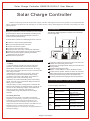
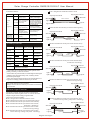
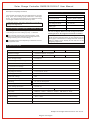
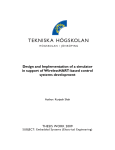
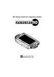
Smart-LF series
Solar Charge Controller
5A/10A/15A/20A
(with Programmable Street-Light Function)
User Manual
Solar Charge Controller SM05/10/15/20-LF User Manual
Solar Charge Controller
Thanks for selecting the Smart series solar charge controller. Although the Smart is very simple to use, please take the
time to read this user manual. This will help you to make full use of many advantages the controller can provide your solar
lighting system.
3.Installation
1.Description
With your new Smart-LF series controller you own a stateof-the art device which was developed according to the
The following diagrams provide an overview of the connections
and the proper order.
latest available technical standards and s uitable for
LiFePO4 r echargeable b attery .
It comes with a number of outstanding features, such as:
●Suitable for LiFePO4 rechargeable battery
●Strong and durable aluminum case, IP67
●12V/24V Automatic recognition
●6 modes for solar street light system
●Dimming function: 30%~70% of rated power adjustable
●Digital Unit to configure Smart charge controller via UART
●External temperature probe measuring the ambient
temperature is more accurate
●Whole electronic protection
⑤
②
①
④
③
⑥
⑦
Digital Unit
2.Safety instructions and waiver of liability
2.1 Safety
①The solar charge controller may only be used in PV
systems in accordance with this user manual and the
specifications of other modules manufacturers. No energy
source other than a solar generator may be connected to the
solar charge controller.
②Batteries store a large amount of energy, never short
circuit a battery under all circumstances. We strongly
recommend connecting a fuse directly to the battery to
protect any short circuit at the battery wiring.
③Batteries can produce flammable gases. Avoid making
sparks, using fire or any naked flame. Make sure that the
battery room is ventilated.
④Avoid touching or short circuiting wires or terminals. Be
aware that the voltages on special terminals or wires can be
as much as twice the battery voltage. Use isolated tools,
stand on dry ground, and keep your hands dry.
⑤Keep children away from batteries and the charge
controller.
2.2 Liability Exclusion
The manufacturer shall not be liable for damages,
especially on the battery, caused by use other than as
intended or as mentioned in this manual or if the
recommendations of the battery manufacturer are
neglected. The manufacturer shall not be liable if there
has been service or repair carried out by any
unauthorized person, unusual use, wrong installation, or
bad system design.
To avoid any voltage on the wires, first connect the wire to the
controller, then to the battery, panel or load.
Make sure the wire length between battery and controller is as
short as possible.
Recommended minimum wire size:
SM05-LF: 1.5 mm²; SM10-LF: 2.5mm²; SM15/20-LF: 4mm².
Be aware that the positive terminal of Smart are connected
together and therefore have the same electrical potential. If any
grounding is required, always do this on the positive wires.
Connecting capacitive load may trigger short circuit protection.
4.LED indications Faults & Alarms
4.1LED Display Explanation
LED
Green
Status
Function
Flash(0.4s/0.4s)
Battery connected,
day detected
On
Battery connected,
night detected
Off
No faults detected
Slow flash(0.5s / 2s)
Dimming
Off
No battery connected
Lighted together
(1second)
Controller start-up
Red
Red
Green
Page 1 of 3 Pages
Solar Charge Controller SM05/10/15/20-LF User Manual
Mode 1.Single time and Dusk to Dawn mode
4.2Faults & Alarms
Status Reason
Remedy
Red LED
Battery is low
on
Load will reconnect as soon
as battery is recharged.
Faults
Loads
are
not
supplied
Switch off all loads. Remove
short circuit. Controller will
Red LED Over current/Short switch on load automatically
circuit of loads/
after max 1 minute.After the
slow flash Over temp
temperature reduces,the load
opens automatically
Check if other sources
Battery voltage too
overcharge the battery.
Red LED high(>15.6/31.2V) If not,controller is damaged.
fast flash Battery wires or
Check battery wires,
battery fuse
fuse and battery.
damaged, battery
has high resistance
Battery is
Red LED Battery has low
empty after
capacity
a short time on
Battery is not
being charged Green
during the day LED on
Solar array faulty
or wrong polarity
Protected *1
Short circuit Protected
Protected *1
Protected *3
Over current
Reverse
Current
Dusk to Dawn
Light off
Mode2.Double time mode (can set the dimming time)
Day/night threshold
Day/night threshold
Sunrise
Sunset
Time 1
Time 2
Dimming
Light off
Light off
Protected *2
Switches off
immediately
Switches off
with delay
Day/night threshold
Day/night threshold
Sunrise
Sunset
Light on
Light off
Time 1
Light off
Light on
Time 2
Light off
Protected
Over voltage Max. 55V *4
Mode 4.Double time mode (can set the load off time,
Full Power + Dimming)
Max. 40V
Under
voltage
Over temp.
Light on
Mode 3.Double time mode (can set the load off time)
Solar terminal Battery terminal Load terminal
Reverse
polarity
Time 1+Time 2
Light off
Light on
5.Safety Features
Sunrise
Sunset
Change battery
Remove faulty connection
/reverse polarity
Day/night threshold
Day/night threshold
Switches off
Day/night threshold
Day/night threshold
switches off the load if the temperature
reaches the set valuel
Sunrise
Sunset
*1 Controller can not protect itself in a 24V system when
polarity of battery or solar is reversed.
*2 Controller can protect itself, but loads might be damaged.
*3 Battery must be protected by fuse, or battery will be
permanently damaged.
*4 The solar panel voltage should not exceed this limit for a
long time as voltage protection is done by a varistor.
Warning: The combination of different error conditions
may cause damage to the controller.
Always remove the error before you continue connecting
the controller.
6.Street-Light Function
Light on
Light off
There are 6 modes available:
Mode 1.Single time and Dusk to Dawn mode
Mode2.Double time mode (can set the dimming time)
Mode 3.Double time mode (can set the load off time)
Mode 4.Double time mode (can set the load off time,
Full Power + Dimming)
Mode 5.Double time mode (can set the load on time
before morning coming)
Mode 6.Double time mode (can set the load on time
before morning coming, Full power + Dimming)
Light off
Dimming
Time 2
Light off
Mode 5.Double time mode (can set the load on time
before morning coming)
Day/night threshold
Day/night threshold
Sunrise
Sunset
Light on
The Smart-LF solar charge controller comes with a
sophisticated Street-light function. It controls the load
output at night and is widely programmable.
Time 1
Time1
Output signal
Light off
Light On
Time2
Light off
Mode 6.Double time mode (can set the load on time
before morning coming, Full power + Dimming)
Day/night threshold
Day/night threshold
Sunrise
Sunset
Light on
Time1
五、信号输出
Light off
Page 2 of 3 Pages
Light off
Time2
Dimming
Light off
Solar Charge Controller SM05/10/15/20-LF User Manual
8.Default Settings
Description of Day/Night threshold,
The controller recognizes day and night based on the solar
array open circuit voltage (only functional in street-light
mode) . This day/night threshold can be modified according
to local light conditions and the solar array used.
Default Settings
Load control mode
It will take effect in next day if the mode of controller is
changed via Digital Unit.
7.Low Voltage Disconnect Function (LVD)
Low voltage disconnect voltage (LVD) : 10.5/21.0V
Mode 1(Dusk to Dawn)
Low voltage disconnect
10.5/21.0V
Low voltage reconnect
11.5/23.0V
Battery type
LiFePO4
Day/Night threshold
3.0/6.0V
You can configure Smart-LF solar charge controller
with Digital Unit. See Digital unit manual for details.
Low voltage reconnect voltage (LVR) : 11.5/23.0V
If the controller goes into low voltage protection, it will
restore only when the battery being recharged and the
voltage reaching the reconnect voltage.
The Setup of Smart-LF series solar charge controller is
almost the same as Smart series, the only difference is the
Battery Type, Load disconnect voltage and Load reconnect
voltage of Smart-LF are already be set and can not be
changed by Digital Unit.
Around oblique line value separately on behalf of 12V and
24V system's value.
9.Technical Data
Model
S M 0 5- L F
Nominal voltage
12V/24V automatic recognition
Max solar current or load current
5A
Over charge voltage
14.6/29.2 V
Over charge release voltage
14.0/28.0 V
Load disconnect voltage
10.5/21.0 V
S M 1 0- L F
10 A
Load reconnect voltage
11.5/23.0 V
Lighting hours
0~18 Hours
Day/Night threshold
3.0~7.5V/6.0~15.0V
Battery type
LiFePO4
Max solar voltage
55V
Max battery voltage
40V
Dimming
30~70% of rated power
Cable length
120mm/80mm
Over voltage protection
15.6/31.2 V
S M 1 5- L F
SM20-LF
15A
20A
Dimensions /Weight
85 x 70 x 20 mm / 200g
Wire size
SM05-LF: 1.5mm²; SM10-LF: 2.5mm²; SM15/20-LF: 4mm²
Typical power consumption
<12mA
Ambient temp.
-40℃ ~ +60℃
Case protection
IP67
Max altitude
4000m
85 x 85 x 20mm/210g
Subject to change without notice. Ver: CL15.
Page 3 of 3 Pages