1
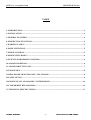
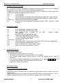
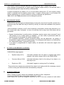
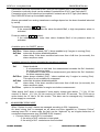
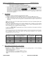
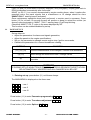
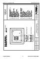
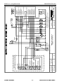
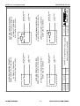
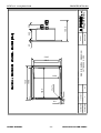
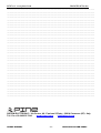
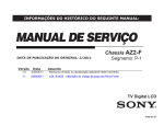
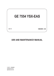
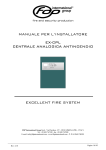
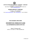
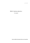
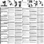
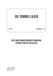
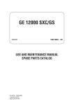
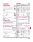
ELECTRONIC PANEL
FOR ALARMS, SECURITIES AND
ENGINE CONTROL
CM30 - GE3A
Series
USER’S MANUAL
PINE s.r.l. www.pinesrl.com
MANGE3AEVA.doc
INDEX
1.INTRODUCTION ....................................................................................................................................... 3
2.INSTALLATION......................................................................................................................................... 4
3.GENERAL FEATURES ............................................................................................................................. 4
4.PUSH BUTTON FUNCTIONS .................................................................................................................. 5
5.WARNING LAMPS .................................................................................................................................... 5
6.PANEL SWITCH-ON ................................................................................................................................. 5
7.ENGINE IGNITION ................................................................................................................................... 5
8.ENGINE SHUT DOWN.............................................................................................................................. 6
9.OUTPUTS (FOR REMOTE CONTROL) ................................................................................................ 6
10.ALARM CONDITONS ............................................................................................................................. 6
11.ALARM CIRCUITS FAULT ................................................................................................................... 7
12.ENGINE RUN............................................................................................................................................ 8
13.RPM / HOURS /MAINTENANCE / OIL CHANGE ............................................................................. 8
14.PANEL SET-UP......................................................................................................................................... 9
15.ENGINE PLANT ANOMALIES / SYSTEM READY......................................................................... 16
16.CONFORMITY DECLARATION ........................................................................................................ 16
17.TECHNICAL SPECIFICATIONS ........................................................................................................ 17
USER’S MANUAL
-1-
CM30 GE3A ALARM PANEL
USER’S MANUAL
UP
Ι ROW
SEL
12 s
-2-
10
9
SERIES GE3A PANEL
19
13
18
8
SEL
17
7
ΙΙΙ ROW
12
SEL
5
ΙΙ ROW
16
6
15
11
4
3
14
1
2
PINE s.r.l. www.pinesrl.com
MANGE3AEVA.doc
CM30 GE3A ALARM PANEL
PINE s.r.l. www.pinesrl.com
1.
MANGE3AEVA.doc
INTRODUCTION
CM30-GE3A is a fully programmable engine control panel controlled by a microprocessor.
It performs the engine automatic start / stop and can manage a gen-set.
The panel provides outputs for interfacing to the main control and monitoring system.
A polycarbonate cover, mounted on an aluminium support, protects control and visualization
part and it can be customized on request. The rear is in painted metal and electrical
connections are with mechanically locked connectors.
All functions performed by CM30-GE3A panel are intuitive and simple: the measurement and
alarm set is also so simple and immediate.
CM30-GE3A has three inputs for ON/OFF alarms and displays up to three measurements:
one in frequency for engine revolutions and two analog. Each of the displayed measurements
can generate an alarm if this option is selected by set-up.
CM30-GE3A reads signals from the most commonly available transducers; on request it can
be adapted to any kind of transducer 4-20mA, 0-10V, ....
Alarms are managed according the ISA –1 sequence.
Each alarm detection can be delayed up to 240 seconds in order to avoid false
signallings or commutations.
RPM input can be used to condition the alarms according to the engine status.
Each alarm can be inhibited when the engine is not running or during ignition: these
conditions are detected through the engine revolutions input.
A connection continuity (or short circuit) fault alarm can be activated on each
measurement/alarm input.
Each alarm can be set to perform the engine shut down.
Q5 input “inhibited safeties” allows deactivating the engine shut down function for all the
alarms except the overspeed alarm.
CM30-GE3A has two power supply input: a main power supply (P2) and a secondary one
(Q12) with optional battery charge. In case of a main power supply fault an alarm will be
generated (16); this alarm cannot be used to shut down the engine.
If the panel works correctly the SYSTEM READY lamp (18) and the SYSTEM READY output
are activated.
There is not the “engine run“ lamp because when engine is running the engine revolutions
are displayed.
Q3 input can be used as alarm or it can excite the battery charge alternator; in this case lamp
(3) becomes the battery charge optical signalling.
USER’S MANUAL
-3-
CM30 GE3A ALARM PANEL
PINE s.r.l. www.pinesrl.com
2.
MANGE3AEVA.doc
INSTALLATION
CM30-GE3A serie engine control panels can be placed on the ship’s pilot bridge or on a
board. Cutting for a proper assembly is shown in D4 drawing.
ALARMS – FAULTS - AUTOMATIC SHUT DOWN TEST
It is possible to test the correct working of alarms and securities (engine shutdown) by
simulating their activation both when engine is off and running.
A transducer simulator is required to test the alarm conditions of analog measurements; if it is
not available, it is sufficient to change the alarm thresholds (see set-up) in order to generate
an alarm also if engine woks properly. After test restore alarm thresholds to the correct
value.
Remember that each alarm will be signalled after the set delay time.
In order to simulate faults on N.O. alarm wiring and on analog measurements, disconnect the
wiring.
NOTE: it is advisable to test all alarms.
3.
GENERAL FEATURES
•
•
•
•
•
•
•
•
•
•
•
•
•
•
•
Visualization of 3 analog measurements on 3 rows with LED display;
13 signal and alarm warning lamps;
Alarm silencing buttons (mute);
Lamp test - keep pressed both button (9) and (10);
Dimmerable high brightness display;
3 inputs for alarms/safeties with continuity or short circuit check;
1 frequency input for engine revolutions - measurement with continuity check;
2 inputs for analog measurements;
“Electrostop connection continuity check” input
Input for remote silencing (remote muting);
Management of the following command inputs:
“Activated/deactivated securities” input
“Remote engine shutdown command” input
“Remote engine ignition command” input
Outputs:
“Engine run” output
“Common failure” output
“System ready” output
“Engine shutdown” output
“Engine ignition” output
“Buzzer” output
“Alternator excitation (D+)” (if AL3 not used)
Maintenance / Oil change management, with countdown timer
Main and secondary power supplies: from 12 up to 24 Vcc (to be selected by set-up);
Size: 162 x 134 x 100 mm;
USER’S MANUAL
-4-
CM30 GE3A ALARM PANEL
PINE s.r.l. www.pinesrl.com
4.
MANGE3AEVA.doc
PUSH BUTTON FUNCTIONS
(11) is used to cycle the visualization of engine revolutions, working hours, hours remaining
to maintenance/oil change, time (in hours) between maintenances.
Combination of leds (14) and (15) show what CM30-GE3A is displaying. Display goes back
to RPM visualization automatically after 4 seconds.
(12)
used in set-up.
(13)
used in set-up.
(9)
used to decrease the displays and warning lamps brightness / used in set-up.
(10)
used to increase the displays and warning lamps brightness / used in set-up.
(9) and (10) perform the lamp test if both are pressed.
(8)
used as alarm acknowledgment/silencing according to ISA-1 sequence / used
in set-up.
5.
WARNING LAMPS
(1)
(2)
(3)
AL1 warning lamp, activated by P4 input.
AL2 warning lamp, activated by P3 input.
AL3 warning lamp, activated by Q4 input / “battery charge”
warning lamp.
(4)
Maintenance/Oil change warning lamp.
(5)
“Stop circuit fault” warning lamp, Q8 input.
(6)
“Over speed alarm” warning lamp, P9 input.
(7)
“Common failure” warning lamp.
(14) and (15) See chapter 13.
(16)
“Main supply fault” warning lamp, monitored on P2 (main power supply) input.
(17)
Alarm on the AN1 measurement, P7 input.
(18)
Show the status of the “System ready” output.
(19)
Alarm on the AN2 measurement, P6 input.
6.
PANEL SWITCH-ON
When panel is switched on:
• Lamp-test is executed (about one second);
• The buzzer is activated during lamp test (about one second);
• The “System ready” warning lamp is turned on and the “System ready” output is
activated;
• The values of analog measurements are displayed; if the option
n
c
(not
connected) was selected, three horizontal lines will appear.
• Inputs and outputs are managed.
7.
ENGINE IGNITION
Engine ignition from remote comand
CM30-GE3A has a command input for automatic engine ignition and an output to drive the
ignition relay.
When the “engine ignition remote command” input (P5 contact) is activated, from 1 up to 5
ingnition attempts are performed by activating the “ignition output” (Q6 contact).
USER’S MANUAL
-5-
CM30 GE3A ALARM PANEL
PINE s.r.l. www.pinesrl.com
MANGE3AEVA.doc
The number of ignition attempts ntA can be chosen by set-up in a range from 1 up to 5.
Each attempt is composed by a ignition period (ignition output active) of t1 seconds and a
pause period (ignition output not active) of t2 seconds.
If engine revolutions are higher of S o A for the whole setting time t E r the engine running
status is reached and the ignition phase ends. If engine running state is not reached the
ignition attempts go on until the maximum number of attempts are performed.
ntA, t1, t2 and SoA parameters can be changed by set-up.
8.
ENGINE SHUT DOWN
CM30-GE3A execute engine shutdown/stop by closing the circuit at Q1 and Q2 contacts for a
maximum stop time tarr that may be select by set-up; an inside self resettable fuse protects
the line.
“Shut down/stop continuity circuit” must be directly connected to electro-stop solenoid (or to
the remote stop relay if present). In case of continuity fault a stop circuit fault alarm will be
generated.
•
Engine shutdown/stop is performed by activating “remote engine stop command” input
(P8 contact) or by a safety alarm (if enabled). If a shut down is performed while an
ignition phase is in progress, the ignition phase ends.
An overspeed shutdown (engine overspeed safety) can be performed by setting a
threshold on engine revolution measurement. The overspeed shut down is not affected by
the “deactivated safety” command (input Q5).
If an alarm is programmed for engine safety, its activation will cause the engine shut
down/stop.
•
•
9.
OUTPUTS (FOR REMOTE CONTROL)
CM30-GE3A output signals:
•
System ready (Q11):
Activated indicates that the panel is supplied and works
properly. Not active means a fault in the CM30-GE3A.
•
Common failure (Q10):
Activated indicates a fault to the wiring of an alarm or to
the stop circuit.
•
Engine run (Q7):
Activated if engine is running (see S o A setting).
These active low outputs are protected from short circuit and provide the necessary current
to drive a relay (see technical notes and assembly example).
10.
ALARM CONDITONS
When “System is ready” alarms are managed according to ISA-1 sequence.
Contacts of ON/OFF alarm transmitters can be N.O. or N.C.
Alarm inputs are active low (negative sensitive) so one of the two contacts of each alarm
USER’S MANUAL
-6-
CM30 GE3A ALARM PANEL
PINE s.r.l. www.pinesrl.com
MANGE3AEVA.doc
transmitter has to be connected to the CM30-GE3A negative pole of the power supply.
Connection continuity check can be enabled if contacts are of N.O. type (fault alarm).
Connection short circuit check can be enabled if contacts are of N.C. type (fault alarm).
See CM30-GE3A set-up for available options.
Alarms generated from analog transducers readings depend on the alarm threshold selected
by set-up.
Temperature reading (
º C option):
if the measurement exceeds the alarm threshold So1, a high temperature alarm is
activated.
Pressure reading ( b A r option):
if the measurement is lower then alarm threshold So1 a low pressure alarm is
activated.
Available option for ON/OFF alarms:
GoF/Gon
AoF/Aon
rit
Alarm always enabled (GoF) / alarm enabled only if engine is running (Gon).
automatic shutdown disabled/enabled.
alarm delay; if the alarm condition lasts more than of rit time (in seconds), the
alarm sequence starts.
Available options for alarms generated by transducer readings:
So1
GoF/Gon
AoF/Aon
rit
GoF/Gon
Alarm threshold
- If a temperature is read and the measurement exceeds the So1 threshold,
the alarm sequence starts.
- If a pressure is read and the measurement goes below the So1 threshold,
the alarm sequence starts.
Alarm always enabled (GoF) / alarm enabled only if engine is running (Gon).
This option is not available for overspeed.
automatic shutdown disabled/enabled.
alarm delay; if the alarm condition lasts more than of rit time (in seconds), the
alarm sequence starts.
option is not available for engine revolutions measurement.
“Main supply fault” alarm is activated if main supply voltage goes below 7 V (for 12 Vdc
version) or below 14 V (for 24 Vdc version) for more than 20 seconds. The 12/24 set-up
option select the 12 Vdc or 24 Vdc version. This alarm can be managed only if secondary
power supply is connected.
11.
ALARM CIRCUITS FAULT
When “System is ready” alarms are managed according to ISA-1 sequence.
An alarm wiring fault is managed as an alarm and also signalled by “Common Failure”
warning lamp ON. In some case the fault can be “deduced” by an irregular behaviour of
correlated measurements (see “ENGINE RUN” chapter”).
• Common failure output (Q10) is activated:
- if the wiring of N.O. contacts is interrupted;
- if the wiring of N.C. contacts are short-circuited.
USER’S MANUAL
-7-
CM30 GE3A ALARM PANEL
PINE s.r.l. www.pinesrl.com
•
•
12.
MANGE3AEVA.doc
An overspeed alarm circuit fault is signalled:
- if the wiring of the RPM transducer is interrupted;
- in the case no. 2) described in “ENGINE RUN” chapter.
Fault to the alarm generated by analog transducer reading is signalled if the reading is
out of range; over range and open circuit are signalled with
C A , under range
and the short circuit are signalled with
C C .
If the alarm is not enabled (setting ESC in option So1) a fault will not be managed as an
alarm but the CA signalling (in case of open circuit) or the CC signalling (in case of short
circuit) will be displayed.
ENGINE RUN
“Engine run” output is activated in the following two cases:
1) Engine revolutions exceed the SoA value for a time longer than tEr (see set-up).
2) Engine revolutions are lower than SoA and the low oil pressure transducer changes its
state as if the engine start running (that is: detections that the engine oil pressure has
risen up).
Case 2) will occur only if AL1 alarm input is set as low (or too low) oil pressure alarm (see
ALP option in set-up).
In this case CM30-GE3A panel use the relation between the oil pressure and the engine
revolutions, deducing if the engine is running or if there is some measurements fault or
some calibration error in engine revolutions reading.
In case 2) an RPM FAULT is generated even if there is continuity in the engine revolutions
measurement circuit.
The following table shows the relation between engine revolutions measurement and engine
low oil pressure alarm (only if the option ALP has been selected for AL1 and the
corresponding circuit is not in fault).
Engine
revolutions > SoA
ENGINE OIL PRESSURE
(as by input alarm)
RPM reading
circuit FAULT
ENGINE RUN
RPM = 0
NO
NO
YES
YES
LOW
LOW
HIGH
LOW
HIGH
NO
YES
YES
NO
NO
NO
NO
YES
YES
YES
Engine running TABLE
13.
RPM / HOURS /MAINTENANCE / OIL CHANGE
Normally on - ROW I - RPM are visualized but by pressing button (11) the following
measure will be cyclically visualized:
- engine working hours
- time to maintenance or oil change (MAINT. / OIL C.)
- time interval between maintenance / oil change (INT.)
- RPM
USER’S MANUAL
-8-
CM30 GE3A ALARM PANEL
PINE s.r.l. www.pinesrl.com
MANGE3AEVA.doc
Leds (14) and (15) show what is currently displayed, as by serigraphy. Display goes back to
RPM visualization automatically after 4 seconds.
MAINT (or OIL C.) is a counter decremented by engine working hours; when it reaches the
presetted value, the panel signals that a maintenance or oil change should be done
(MAINT./OIL C. warning lamp is activated).
Once maintenance operations have been performed, a counter reset is necessary. Press
button (13) for at least 12 seconds (buzzer will produce a beep) to reload the counter (as
shown in panel serigraphy). MAINT. / OIL C. warning lamp (5) will stop blinking.
Check that MAINT. / OIL C. value is the same displayed by INT.
This function can be enabled/disabled by set-up.
14.
PANEL SET-UP
Set-up allows to:
• Adjust the parameters for alarms and signals generation;
• Adjust the panels to the engine specifications;
• Set-up the parameter to manage remote engine stop / ignition commands;
• Calibrate the parameters for a correct transducers reading.
BUTTONS
(11) (12) (13)
(9) (10)
FUNCTION
Choose measurements to be changed / Confirm new calibrations
Move through the main-menu rows / Change values
Go back to the previous menu level and exit from set-up saving the
new data
(8)
WARNING
IF DURING SET-UP NO BUTTON IS PRESSED, AFTER 60 SECONDS THE SET UP WILL
BE AUTOMATICALLY ABORTED AND ALL CHANGES WILL BE LOST.
1 – Entering set-up: press button (11) until buzzer beeps.
The MAIN MENU is displayed on the three rows:
P
r n
t A
r
O P t
- row I
- row II
- row III
Press button (11) to enter Parameter programming P
r n .
Press button (12) to enter Transducer adjustment t A
Press button (13) to enter Options O P t
USER’S MANUAL
-9-
r .
.
CM30 GE3A ALARM PANEL
PINE s.r.l. www.pinesrl.com
P
MANGE3AEVA.doc
n - PARAMETER PROGRAMMING.
r
S
E
t - is displayed on the first row.
2- By pressing buttons (9) and (10) user can select which row/alarm to modify as indicated
by SEt and by the AL1, AL2, AL3 led.
3- Press button on the right side of SEt for analogs, and on the right side of AL1, AL2, AL3
for ON/OFF alarms, to enter the parameter selection menu. When AL1,AL2, AL3 are
displayed, the corresponding warning lamp lights.
4- Press buttons (9) and (10) to change the value of the selected parameter.
Continue until Set or AL1, AL2, AL3 appears again. If others parameter has to be
changed, proceed as from step 2.
5- When all necessary changes have been made, exit from set-up in the proper way to store
new data. User can properly exit at any step of set-up and at any moment, by
pressing button (8) once or more times.
SEt sub-menu - Code table of inputs and transducers.
ROW I:
Pressing button (11) the combinations of the leds (in the right of the
display) will change showing the parameter that can be changed.
Legend:
led turned off
led turned on
Advance in the menu by pressing button in the right of the display and change value by
pressing button (9) or (10)
S E
r
t
P n
RPM
/
Pressing button (11) the display shows:
n c
RPM are measured / this input is not used
Change by pressing button (9), (10) and confirm pressing button (11).
By pressing button (11), options and overspeed alarm can be setted as described in “Set
sub-menu - alarm conditions setting code table”.
S E
USER’S MANUAL
t
x x x x
Working hours.
- 10 -
CM30 GE3A ALARM PANEL
PINE s.r.l. www.pinesrl.com
MANGE3AEVA.doc
S E
t
x x x x
Hours to next maintenance / oil change.
S E
t
x x x x
Time interval (hours) between maintenance / oil change.
Note: maintenance / oil change is displayed only if Oon option was set in OPt menu.
ROWS II and III :
codes displayed after Set by pressing the button on the
right-hand side.
Each row is related to an analog input:
•
The II row - LED below – corresponds to AN1, P7 contact
•
The III row - LED below – corresponds to AN2, P6 contact
With the following options you can choose which type of transducer is read from the analog
input:
(P7 contact)
º C
/
n c (if this input is not used)
1 2 0 VDO 120 º
1 5 0 VDO 150 ºC
(P6 contact)
b A r
/
n c (if this input is not used)
d 2 VDO 2 bar
d 5 VDO 5 bar
d 1 0 VDO 10 bar
d 2 5 VDO 25 bar
Buttons (9) and (10) to change transducer and button on the right side of display for confirm
and continue the set-up.
If a different transducer from the programmed one is erroneously connected to input,
the value will be misread, visualization will be wrong and false alarms could occur.
SEt sub-menu - Alarm condition setting code table
Codes displayed after choosing transducer type:
S o 1 / E S C
Alarm threshold value / threshold disabled
S o 1 - x
Set the So1 value and continue
x
x
G o n / G o F
USER’S MANUAL
Alarm activated only when engine is running / always activated
- 11 -
CM30 GE3A ALARM PANEL
PINE s.r.l. www.pinesrl.com
MANGE3AEVA.doc
A o n / A o F
Activates/deactivates automatic stop
r
Delay time for alarm detection, from 0 up to 240 seconds
i t
- x
x
x
Values are set by buttons (9) and (10).
To exclude any threshold, value must be increased until ESC appears on display.
AL1/2/3 sub-menu - ON / OFF alarms setting code table
These codes appear after AL1, AL2, AL3:
A L P / A L L
Low (or too low) oil pressure alarm / generic alarm.
This setting is valid only for AL1 alarm, P4 input
A L b / A L L
battery charge warning lamp / generic alarm.
This setting is valid only for AL3 alarm, Q3 input
G o n / G o F
Alarm activated only when engine is running / always activated.
This setting appears for AL2, AL3 input and for AL1 input only if
set as generic alarm (ALL)
A o n / A o F
Activates/deactivates automatic stop
n o S c N.O. type alarm, without wiring fault check (electrical continuity)
n o C c N.O. type alarm, with wiring fault check (electrical continuity)
n c S c N.C. type alarm, without wiring fault check (short circuit)
n c C c N.C. type alarm, with wiring fault check (short circuit)
r
i t
- x x x
Delay time – set value
Once delay time value has been confirmed, AL1/2/3 sub-menu appears again.
t
A
r - TRANSDUCER AND RPM CALIBRATION.
r A
P
- RPM calibration
S o
A
- Threshold calibration (RPM) in order to declare the engine is running
t
- Times setting
Press button on the display right side selecting rAP , SoA or t and continue confirming the
options in the same way.
r A
P
displays show:
x x x x
x x x
USER’S MANUAL
Engine revolutions (rPn) or Ratio (rAP)
rPn or rAP
by pressing button (12)
- 12 -
CM30 GE3A ALARM PANEL
PINE s.r.l. www.pinesrl.com
x x x
MANGE3AEVA.doc
r1 or r10
by pressing button (13)
Button (12) allows to choose if RPM (rPn) or Ratio (rAP) has to be displayed.
Button (13) allows to choose revolutions counter resolution. It can be either 1 revolution per
minute (r1) or 10 revolutions per minute (r10).
Note: Ratio (rAP) means number of pulses for every engine revolution.
If ratio is known, select the rAP visualization by button (12) and set pressing buttons (9) and
(10).
If ratio is unknown, select the visualization of RPM pressing button (12) (rPn) and set the
same value read by a precision revolution counter, using buttons (9) and (10). Repeat this
operation to low, medium and high rate for a more accurate regulation.
Note: If panel dispose of a PINE magnetic pick-up adapter, Ratio (rAP) to be set is obtained
dividing by 16 the number of pulse per engine revolution.
If engine revolutions are higher of S o A for the whole setting time t E r the engine running
status is reached.
S o A
displays show:
x x x x
Engine running threshold value (RPM)
Buttons (9) and (10) allows to set the engine running RPM value.
t
the following menu appears:
t A A
Stop relays activation time (engine stop phase).
t
Engine running delay time.
E
r
t A v
Time for automatic engine ignition.
Times are in seconds
Choose, by the buttons (11) or (12) or (13) tAA or tEr or tAv and continue:
t A A
x x x
display show:
STOP relay starting up time value
(in seconds)
tAA value is set by buttons (9) and (10).
t
E
r
displays show:
x x x
Engine running delay time.
(in seconds)
USER’S MANUAL
- 13 -
CM30 GE3A ALARM PANEL
PINE s.r.l. www.pinesrl.com
MANGE3AEVA.doc
tEr value is set by buttons (9) and (10).
t A v
the following menu appears:
t 1
Ignition relay activation time during an engine ignition attempt
t 2
Ignition relay turning off time (pause before attempting another
engine ignition phase).
Choose, by the button on the display right side, t1 or t2 and go ahead:
t 1
Choose t1 by button (12); the display shows:
x x x
Ignition relay activation time
(in seconds)
t 1 value is set by buttons (9) and (10).
t 2
Choose t2 by button (13); the display shows:
x x x
Ignition relay turning off (in seconds)
t 2 value is set by buttons (9) and (10).
O P
t - OPTIONS.
Menu displays:
O P 1
O P 2
O P 3
O P 1
n t A
Choose OP1 by button (11); the display shows:
Number of Ignition attempts
O I L
USER’S MANUAL
- 14 -
CM30 GE3A ALARM PANEL
PINE s.r.l. www.pinesrl.com
MANGE3AEVA.doc
Choose, by the button on the display right side, n t A or OIL and go ahead:
Choosing n t A by button (11) display shows:
n t A x
Number of Ignition attempts (x varies from 1 up to 5)
Number of Ignition attempts is set by buttons (9) and (10).
Choosing OIL by button (12) display shows:
O o n/F
Oon or OoF Maintenance (Oil change) activated / deactivated
Choose using buttons (9) and (10).
O P 2
Choose OP2 by button (12); the display shows:
L o n/F
Brightness intensity memory is activated / deactivated
Use button (9) e (10)
O P 3
Choose OP3 by button (13); the display shows:
1 2 /
2 4 12Vcc or 24Vcc power supply
In order to return to previous menu or to main menu or in order to exit and set-up storing
new data, press button (8) once or more times.
USER’S MANUAL
- 15 -
CM30 GE3A ALARM PANEL
PINE s.r.l. www.pinesrl.com
15.
MANGE3AEVA.doc
ENGINE PLANT ANOMALIES / SYSTEM READY
At turning on and during normal working the CM30-GE3A checks the stored data (set-up) in
an internal memory. If the panel works correctly and it is right supplied, the “System ready”
signal is sent to Remote Control and led (18) is on. If “System ready” is not active and in the
first display row appears “Ed” (data error) followed by a number (indicating the type of
internal memory fault), it means that there is some problem in data memory read/write
operations. In this case you can try to enter set-up and verify parameters, restoring the lost
ones. Exiting set-up the memory is written again; if “Ed” (data error) appears again it is
necessary to contact CM30-GE3A supplier in order to repair the panel.
If there are not the main and the secondary power supply or if there is a panel fault, “System
ready” output will not be activated.
RPM measurement:
•
•
•
16.
CM30-GE3A check the pick-up circuit continuity (when engine if stop) and the
presence of RPM pulses during engine ignition time.
In case of a fault of one or both the test and in compliance with “ENGINE RUNNING
table” the CM30-GE3A signal a “RPM circuit fault”. In this case further engine ignition
attempts will not be performed.
When an input has been set as low or too low oil pressure alarm, if engine revolutions
are below the SoA threshold and pressure transducer is not in an alarm condition,
CM30-GE3A will signal an “RPM circuit fault” even if there could be a pressure
transducer fault.
CONFORMITY DECLARATION
Manufactures declares that the engine control panel of series CM30 GE3A is in
conformity at European requirements of electromagnetic compatibility and of
safety with directives 2006/95/EEC (ex 73/23/EEC), 89/336/EEC, 92/31/EEC,
93/68/EEC, 93/97/EEC, EN 60945, and RINA RULES ed. 2007.
USER’S MANUAL
- 16 -
CM30 GE3A ALARM PANEL
PINE s.r.l. www.pinesrl.com
17.
MANGE3AEVA.doc
TECHNICAL SPECIFICATIONS
Nominal voltage from 12 up to 24Vcc (min 7 max 35Vcc) with “main supply fault” alarm if:
option 12V, supply below 7V for more than 20 seconds
option 24V, supply below 14V for more than 20 seconds
MAIN
POWER SUPPLY
SECONDARY
As the main one, without alarm – with recharge circuit if a stop-gap battery is used
POWER CONSUMPTION (no load)
Less than 10 Watt
Polarity inversion, Battery disconnecting extravoltage
(not repetitive).
PROTECTIONS
TEMPERATURE
WORKING TEMPERATURE
-25 +55 °C
STORAGE TEMPERATURE
-30 +80 °C
RELATIVE HUMIDITY
VISUALIZATION
Max 95 %
3 rows led display
3 warning lamps for alarms
Overspeed
Stop line fault
Common failure
Maintenance / Oil change
2 warning lamp for: RPM/HOURS/MAINT./INT.
Analog measurement 1 alarm
Alnalog measurement 2 alarm
Main supply fault
“System ready” warning lamp (System ready output repetition)
WARNING LAMP
SIGNALLINGS
ACOUSTIC INDICATION
Buzzer output
Alternator "W" (with 10KΩ resistor in parallel)
ENGINE REVOLUTIONS with line continuity
check
PNP PROXIMITY SENSOR (with 10KΩ resistor in parallel)
Pick-up on crown wheel (impedance from
Vout from 3 up to 50Vrms) (with PINE adapter)
INPUT FOR
READINGS-ALARMS
2 ANALOG INPUTS from commercial resistive
transducer (4-20 mA on demand)
AL1
ALARMS
AL2
AL3
INPUTS from N.C. or N.O. type
contacts with possible continuity or Open circuit voltage:
5 Vdc
short circuit check by installing a Short circuit voltage: 0-2Vdc - 0,5 mA
10KΩ resistor in parallel or in series Voltage for continuity/short circuit test, with 10KΩ resistor:
to the contact
IGNITION
ACTIVE to positive supply +/- 20% - 5 mA
STOP
ACTIVE to positive supply +/- 20% - 5 mA
DEACTIVATED SECURITIES
USER’S MANUAL
to
2,5 Vdc
Fault if open circuit
REMOTE MUTING INPUT
OUTPUTS SHORT CIRCUIT
PROTECTED
up
20KΩ,
TEMPERATURE from 0 up to 120°C with VDO 40 - 120 °C transducer,
da 0 a 150 with VDO 40 - 150 °C transducer.
PRESSURES from 0 bar up to F.S. select by set-up
Other models on demand
CONTINUITY TEST ELETTROSTOP CONNECTION LINE
REMOTE COMANDS INPUTS
1
ACTIVE to positive supply +/- 20% - 5 mA
ACTIVE to positive supply +/- 20% - 5 mA
ENGINE STOP
Positive supply, Imax = 2A
IGNITION
Negative supply, Imax = 300 mA
- 17 -
CM30 GE3A ALARM PANEL
PINE s.r.l. www.pinesrl.com
MANGE3AEVA.doc
ENGINE RUN
Negative supply, Imax = 300 mA
COMMON FAILURES
Negative supply, Imax = 300 mA
SYSTEM READY
Negative supply, Imax = 300 mA
BUZZER (ACOUSTIC SIGNALLING)
Negative supply, Imax = 10 mA
ALTERNATOR EXCITATION
Positive supply, Imax = 100 mA
MEASURE PRECISIONS (sensors / transmitters not included):
ENGINE RPM:
TEMPERATURES:
PRESSURES:
± 0,5% ± 1DGT, 1 or 10 RPM risolution, as by set-up setting
± 2% ± 1DGT
± 2% ± 1DGT
Note: For other transducer types please contact PINE s.r.l.
USER’S MANUAL
- 18 -
CM30 GE3A ALARM PANEL
USER’S MANUAL
- 19 -
DSDXG3A01A
CODICE / CODE :
DSDXG3A01A
RIF. FILE / FILE REF. :
A
REV. / REV. :
05/07/2007
DATA / DATE :
D1
FOGLIO / SHEET :
SCALA / SCALE :
CONNETTORE Q MINIFIT 12p
MINIFIT 12p Q CONNECTOR
CONNETTORE P MINIFIT 10p
MINIFIT 10p P CONNECTOR
CONNETTORI CENTRALINA
ELETTRONICA DI CONTROLLO
ELECTRONIC CONTROL UNIT CONNECTORS
DESCRIZIONE / DESCRIPTION :
6 5 4 3 2 1
12 11 10 9 8 7
5 4 3 2 1
10 9 8 7 6
VISTA POSTERIORE
PADOAN M.
APPROVATO / APPROVED :
DA RE L.
DISEGNATO / DESIGNED :
Chioggia (VE) - Italy
PINE s.r.l. www.pinesrl.com
MANGE3AEVA.doc
CM30 GE3A ALARM PANEL
- 20 -
DSDXG3A02A
CODICE / CODE :
DSDXG3A02A
RIF. FILE / FILE REF. :
A
REV. / REV. :
10/07/2007
DATA / DATE :
CM PRONTO
SYSTEM READY
CUMULATIVO
ALLARMI
COMMON
FAILURE
D2
FOGLIO / SHEET :
SICUREZZE DISINSERITE
DEACTIVATED SECURITIES
MOTORE IN MOTO
ENGINE RUN
TACITAZ.
MUTING
ARRESTO
STOP
AVVIAM.
IGNITION
FUSIBILE
FUSE
ARR
ESEMPIO DI CABLAGGIO
ASSEMBLY EXAMPLE
DESCRIZIONE / DESCRIPTION :
ALIMENTAZIONE
PRINCIPALE
MAIN POWER
SUPPLY
AVV
FUSIBILE
FUSE
IN ALTERNATIVA
IN ALTERNATIVE
R
AL1
R
AL2
RELE' STOP AUTOMATICO (CONTATTO C)
AUTOMATIC STOP RELAY (C CONTACT)
Q2
Q3
ALIMENTAZIONE
SECONDARIA
SECONDARY
POWER SUPPLY
Q12
Q11
Q10
Q9
Q8
Q7
Q6
Q5
Q4
PADOAN M.
APPROVATO / APPROVED :
DA RE L.
DISEGNATO / DESIGNED :
Chioggia (VE) - Italy
s.r.l.
INGRESSO DI ALLARME AL3
ALARM INPUT AL3
USCITA CICALINO (NEGATIVO)
BUZZER OUTPUT (NEGATIVE)
SICUREZZE DISINSERITE
DEACTIVATED SECURITIES
USCITA AVVIAMENTO
ENGINE IGNITION OUTPUT
USCITA MOTORE IN MOTO
ENGINE RUN OUTPUT
CONTINUITA' CIRC. DI ARRESTO
STOP CIRCUIT CONTINUITY
INGRESSO TACITAZIONE REMOTA
REMOTE MUTING OUTPUT
USCITA CUMULATIVO ALLARMI
COMMON FAILURE OUTPUT
USCITA CM PRONTO
SYSTEM READY OUTPUT
+ ALIMENTAZIONE SECONDARIA
+ SECONDARY POWER SUPPLY
RELE' STOP AUTOMATICO (CONTATTO NO)
AUTOMATIC STOP RELAY (N.O. CONTACT)
Q1
P9
P8
P7
P6
P5
P4
P3
P2
P10
CM30 - GE3A
ECC. GEN. CARICA BATT. (D+)
EXC. BATT. CHARGE GEN. (D+)
+ ALIMENTATORE PRINCIPALE
+ MAIN POWER SUPPLY
ING. DI ALLARME AL2
ALARM INPUT AL2
INGRESSO DI ALLARME AL1
ALARM INPUT AL1
ING. "COM REM. AVV. MOTORE"
"ENGINE IGNITION REMOTE COM." INPUT
INGRESSO ANALOGICO AN2
ANALOG INPUT AN2
INGRESSO ANALOGICO AN1
ANALOG INPUT AN1
ING. "COM REM. ARR. MOTORE"
"ENGINE STOP REMOTE COM." INPUT
INGRESSO GIRI MOTORE
ENGINE REVOLUTIONS INPUT
- ALIMENTAZIONE
- POWER SUPPLY
P1
AL1 - AL2 - AL3 : ALLARMI NORMALMENTE APERTI CON
CONTROLLO DI CONTINUITA' (R=10K Ω)
AL1 - AL2 - AL3 : NORMALLY OPEN ALARM WITH
CONTINUITY CONTROL (R=10K Ω)
AL3
USER’S MANUAL
R
COMANDI ED USCITE REMOTI
REMOTE COMMANDS AND OUTPUTS
PINE s.r.l. www.pinesrl.com
MANGE3AEVA.doc
CM30 GE3A ALARM PANEL
AN1
AN2
SENSORE GIRI
RPM TRANSD.
USER’S MANUAL
- 21 -
DSDXG3A03A
CODICE / CODE :
DSDXG3A03A
RIF. FILE / FILE REF. :
A
REV. / REV. :
14/09/2007
DATA / DATE :
D3
FOGLIO / SHEET :
SCALA / SCALE :
ALARMS CONNECTION SCHEME
PADOAN M.
APPROVATO / APPROVED :
DA RE L.
DISEGNATO / DESIGNED :
10KΩ
Chioggia (VE) - Italy
- ALIMENTAZIONE
- SUPPLY
INGRESSO GENERICO
GENERIC INPUT
NORMALLY CLOSED ALARM WITH
SHORT CIRCUIT CONTROL
SCHEMA DI COLLEGAMENTO DEGLI ALLARMI
DESCRIZIONE / DESCRIPTION :
- ALIMENTAZIONE
- SUPPLY
INGRESSO GENERICO
GENERIC INPUT
NORMALLY CLOSED ALARM WITHOUT
SHORT CIRCUIT CONTROL
ALLARME NORMALMENTE CHIUSO
CON CONTROLLO DI CORTOCIRCUITO
- ALIMENTAZIONE
- SUPPLY
- ALIMENTAZIONE
- SUPPLY
ALLARME NORMALMENTE CHIUSO
SENZA CONTROLLO DI CORTOCIRCUITO
INGRESSO GENERICO
GENERIC INPUT
10KΩ
ALLARME NORMALMENTE APERTO
CON CONTROLLO DI CONTINUITA'
NORMALLY OPEN ALARM
WITH CONTINUITYCONTROL
INGRESSO GENERICO
GENERIC INPUT
NORMALLY OPEN ALARM
WITHOUT CONTINUITY CONTROL
ALLARME NORMALMENTE APERTO
SENZA CONTROLLO DI CONTINUITA'
PINE s.r.l. www.pinesrl.com
MANGE3AEVA.doc
CM30 GE3A ALARM PANEL
USER’S MANUAL
- 22 -
DSDXG3B04A
11/07/2007
A
D4
FOGLIO / SHEET :
DIME DI FORATURA - DIMENSIONI
CUTTING EDGE - SIZE
DESCRIZIONE / DESCRIPTION :
118.4
REV. / REV. :
SCALA / SCALE :
122.0
CODICE / CODE :
6.0
DATA / DATE :
134.0
DSDXG3B04A
RIF. FILE / FILE REF. :
6.0
FORO ∅ 3,5 mm
SVASATO ∅ 4,5 mm
146.8
150.0
162.0
4.0
PADOAN M.
APPROVATO / APPROVED :
DA RE L.
DISEGNATO / DESIGNED :
55.0
Chioggia (VE) - Italy
100.0
20.4
PINE s.r.l. www.pinesrl.com
MANGE3AEVA.doc
CM30 GE3A ALARM PANEL
PINE s.r.l. www.pinesrl.com
MANGE3AEVA.doc
......................................................................................................................................
......................................................................................................................................
......................................................................................................................................
......................................................................................................................................
......................................................................................................................................
......................................................................................................................................
......................................................................................................................................
......................................................................................................................................
......................................................................................................................................
......................................................................................................................................
......................................................................................................................................
......................................................................................................................................
......................................................................................................................................
......................................................................................................................................
......................................................................................................................................
......................................................................................................................................
......................................................................................................................................
......................................................................................................................................
......................................................................................................................................
......................................................................................................................................
......................................................................................................................................
......................................................................................................................................
......................................................................................................................................
......................................................................................................................................
......................................................................................................................................
......................................................................................................................................
......................................................................................................................................
......................................................................................................................................
......................................................................................................................................
......................................................................................................................................
......................................................................................................................................
......................................................................................................................................
......................................................................................................................................
......................................................................................................................................
......................................................................................................................................
SISTEMI ELETTRONICI - Via Centro, 49 - Frazione S.Pietro - 30014 Cavarzere (VE) - Italy
Tel / Fax +39.0426.35.70.41
www.pinesrl.com
[email protected]
USER’S MANUAL
- 23 -
CM30 GE3A ALARM PANEL